EP1493222B1 - Linear voice coil actuator as a controllable electromagnetic compression spring - Google Patents
Linear voice coil actuator as a controllable electromagnetic compression spring Download PDFInfo
- Publication number
- EP1493222B1 EP1493222B1 EP03719553A EP03719553A EP1493222B1 EP 1493222 B1 EP1493222 B1 EP 1493222B1 EP 03719553 A EP03719553 A EP 03719553A EP 03719553 A EP03719553 A EP 03719553A EP 1493222 B1 EP1493222 B1 EP 1493222B1
- Authority
- EP
- European Patent Office
- Prior art keywords
- coil
- assembly
- soft magnetic
- energized
- coil assembly
- Prior art date
- Legal status (The legal status is an assumption and is not a legal conclusion. Google has not performed a legal analysis and makes no representation as to the accuracy of the status listed.)
- Expired - Lifetime
Links
- 230000006835 compression Effects 0.000 title claims description 6
- 238000007906 compression Methods 0.000 title claims description 6
- 230000003993 interaction Effects 0.000 claims abstract description 7
- 238000004804 winding Methods 0.000 description 2
- BGPVFRJUHWVFKM-UHFFFAOYSA-N N1=C2C=CC=CC2=[N+]([O-])C1(CC1)CCC21N=C1C=CC=CC1=[N+]2[O-] Chemical compound N1=C2C=CC=CC2=[N+]([O-])C1(CC1)CCC21N=C1C=CC=CC1=[N+]2[O-] BGPVFRJUHWVFKM-UHFFFAOYSA-N 0.000 description 1
- 230000007423 decrease Effects 0.000 description 1
- 230000003247 decreasing effect Effects 0.000 description 1
- 230000001419 dependent effect Effects 0.000 description 1
- 239000000696 magnetic material Substances 0.000 description 1
- 230000004048 modification Effects 0.000 description 1
- 238000012986 modification Methods 0.000 description 1
Images

Classifications
-
- H—ELECTRICITY
- H02—GENERATION; CONVERSION OR DISTRIBUTION OF ELECTRIC POWER
- H02K—DYNAMO-ELECTRIC MACHINES
- H02K41/00—Propulsion systems in which a rigid body is moved along a path due to dynamo-electric interaction between the body and a magnetic field travelling along the path
- H02K41/02—Linear motors; Sectional motors
- H02K41/035—DC motors; Unipolar motors
- H02K41/0352—Unipolar motors
- H02K41/0354—Lorentz force motors, e.g. voice coil motors
- H02K41/0356—Lorentz force motors, e.g. voice coil motors moving along a straight path
-
- H—ELECTRICITY
- H02—GENERATION; CONVERSION OR DISTRIBUTION OF ELECTRIC POWER
- H02K—DYNAMO-ELECTRIC MACHINES
- H02K33/00—Motors with reciprocating, oscillating or vibrating magnet, armature or coil system
- H02K33/16—Motors with reciprocating, oscillating or vibrating magnet, armature or coil system with polarised armatures moving in alternate directions by reversal or energisation of a single coil system
-
- H—ELECTRICITY
- H01—ELECTRIC ELEMENTS
- H01F—MAGNETS; INDUCTANCES; TRANSFORMERS; SELECTION OF MATERIALS FOR THEIR MAGNETIC PROPERTIES
- H01F7/00—Magnets
- H01F7/06—Electromagnets; Actuators including electromagnets
- H01F7/066—Electromagnets with movable winding
-
- H—ELECTRICITY
- H02—GENERATION; CONVERSION OR DISTRIBUTION OF ELECTRIC POWER
- H02K—DYNAMO-ELECTRIC MACHINES
- H02K41/00—Propulsion systems in which a rigid body is moved along a path due to dynamo-electric interaction between the body and a magnetic field travelling along the path
- H02K41/02—Linear motors; Sectional motors
- H02K41/035—DC motors; Unipolar motors
-
- H—ELECTRICITY
- H01—ELECTRIC ELEMENTS
- H01F—MAGNETS; INDUCTANCES; TRANSFORMERS; SELECTION OF MATERIALS FOR THEIR MAGNETIC PROPERTIES
- H01F7/00—Magnets
- H01F7/06—Electromagnets; Actuators including electromagnets
- H01F7/08—Electromagnets; Actuators including electromagnets with armatures
- H01F7/13—Electromagnets; Actuators including electromagnets with armatures characterised by pulling-force characteristics
Definitions
- the present invention relates to a linear actuator comprising a field assembly establishing a magnetic field, and a coil assembly positioned for magnetic interaction with and movement relative to the field assembly, the movement defining a stroke
- the field assembly includes a soft magnetic housing defining an axis, and a plurality of axially magnetized cylindrical magnets positioned along an axis of and in the housing and spaced apart from one another by at least one soft magnetic pole piece
- the coil assembly includes a coil base having a coil cavity and a coil positioned in the coil cavity, and the stroke of the actuator being defined by energized and de-energized states of the coil assembly.
- a linear actuator of the kind defined by the preceding paragraph is described in U.S. Patent 5 345 206 .
- Other known actuators are described in JP 59080145 , EP 1001512 , and US Patent 4 439 700 .
- a typical linear voice coil actuator 1 depicted, for example, in a one-half longitudinal cross section view in Fig. 1 consists of a field assembly 2 and a coil assembly 3.
- Field assembly 2 is comprised of an axially magnetized cylindrical magnet 4, soft magnetic pole piece 5 and soft magnetic housing 6.
- Coil assembly 3 consists of a coil 8, located in the circular cavity of the coil base 7. The coil assembly 3, when de-energized, does not have a preferred position to go to. If, on the other hand, after being de-energized, a coil has to move away from the field assembly, then some kind of feature providing repulsion force has to be present. This repulsion force is typically provided by a mechanical spring. The predictability of the characteristics of the repulsion force are therefore dependent upon and subject to the variations in mechanical characteristics of the spring. It is therefore desirable to have a linear voice coil actuator having a repulsion force which is not subject to the variations in mechanical characteristics of a mechanical spring.
- a linear actuator of the kind defined hereinbefore is characterized in that an axially magnetized permanent magnet is positioned on the coil base to interact with the magnetic field of the field assembly and to travel along the axis of the housing, whereby the actuator is controllable as a spring throughout the stroke.
- a preferred embodiment of the invention provides a linear voice coil actuator operating as a controllable electromagnetic compression spring.
- the preferred linear actuator can be controlled by the current in coils within the actuator. When this actuator feature is employed, there is no need to use a mechanical spring to provide a repulsion force.
- a repulsion force is generated between the coil assembly and the field assembly when the coil assembly is de-energized, and the soft magnetic housing of the aforementioned field assembly has an overhang relative to the soft magnetic pole piece which affects the amount of repulsion force generated.
- a repulsion force is generated between the coil assembly and the field assembly when the coil assembly is de-energized, and the magnitude of the repulsion force can be modified when the coil assembly is energized, and further wherein the soft magnetic housing of the aforementioned field assembly has an overhang relative to the soft magnetic pole piece which affects the magnitude of repulsion forces generated.
- the resultant force has a first direction when the coil assembly is energized at one level, and has a second direction, opposite the first direction, when the coil assembly is energized in a different level.
- the linear actuator may comprise a field assembly and a coil assembly positioned for interaction with and movement relative to the field assembly, wherein the field assembly includes a soft magnetic housing, a plurality of axially magnetized cylindrical magnets and a plurality of soft magnetic pole pieces which form a stack of alternating cylindrical magnets and pole pieces.
- the stack is positioned along an axis of and in the soft magnetic housing, so that one of the magnets is positioned against the soft magnetic base, and one of the pole pieces is located at a free end of the stack.
- the coil assembly includes a coil base having coil cavities, a plurality of coils supported in the coil cavity, and an axially magnetized permanent magnet positioned on the coil base so that the axially magnetized permanent magnet is positioned to travel along the axis of the soft magnetic housing.
- the preferred linear voice coil actuator in accordance with the invention provides a repulsion force so that it can operate as an electromagnetic compression spring controlled by currents in its coils.
- the preferred actuator is depicted in a one-half longitudinal cross section and is a modified version of a design that is disclosed in U.S. Pat. No. 5,345,206 .
- the coil assembly 22 has an additional element: an axially magnetized permanent magnet 18 attached to the coil base 19.
- the linear voice coil actuator 10 is shown in a fully-in position. Because of this permanent magnet 18, the coil assembly 22 tends to move away (to the right) from the field assembly 24 as long as the winding (comprising coils 13 and 16) is not energized.
- the distance that the coil assembly 22 moves is determined by the relationship between the repulsion force as a function of stroke and the friction in the system. Therefore, either a positive stop (not shown) should be provided or a system itself should limit the motion.
- the repulsion force of this actuator 10 for the given position is affected by several variables: thickness of the magnet 18, its inside and outside diameters, the amount of the overhang 20 of the soft magnetic housing 11 relative a soft magnetic pole 17, and, generally, by the geometry of an actuator and by the characteristics of soft and hard magnetic materials from which the magnetic circuit of such an actuator is built.
- the coil assembly 22 When the coils are energized, the coil assembly 22 will remain in a fully-out position as long as the force created by interaction of the current in the coils 13 and 16 and the magnetic field generated by axially magnetized permanent magnets 12 and 15 is less than or equal to the repulsion force created by an additional permanent magnet 18. Once this force becomes greater than the repulsion force, the coil assembly will move into the field assembly.
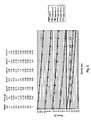
- Fig. 3 shows a family of the force vs. stroke characteristics of the actuator 10 of the present invention at different numbers of Ampere-turns.
- the actuator 10 acts like a compression spring with force being greatest at the end of travel for coil assembly 22, and least at the starting point of travel.
- Ampere-turns applied to coil assembly 22 for example 160A-T or 175A-T, it can be seen that the actuator 10 acts to supply a force, which causes the coil assembly to move in opposite direction.
- one of the applications of the actuator of the present invention can be in a valve.
- the valve When the coils are not energized, the valve is closed (e.g. in the 1 mm stroke position) and the actuator applies a force of 10.2N to keep the valve closed. It takes a certain amount of current in the winding (i.e. a certain number of Ampere-turns) to overcome the repulsion force (present in the actuator because of permanent magnet 18) and thereby open the valve.
- the minimum number of Ampere-turns which would be applied to keep the valve open throughout the stroke is 160.
- the present invention provides an actuator that can be considered as an electromagnetic compression spring controlled by the current in the coils.
- this actuator feature is employed, there is no need to use a mechanical spring.
Abstract
Description
- The present invention relates to a linear actuator comprising a field assembly establishing a magnetic field, and a coil assembly positioned for magnetic interaction with and movement relative to the field assembly, the movement defining a stroke, wherein the field assembly includes a soft magnetic housing defining an axis, and a plurality of axially magnetized cylindrical magnets positioned along an axis of and in the housing and spaced apart from one another by at least one soft magnetic pole piece, and wherein the coil assembly includes a coil base having a coil cavity and a coil positioned in the coil cavity, and the stroke of the actuator being defined by energized and de-energized states of the coil assembly.
- A linear actuator of the kind defined by the preceding paragraph is described in
U.S. . Other known actuators are described inPatent 5 345 206JP 59080145 EP 1001512 , andUS .Patent 4 439 700 - A typical linear
voice coil actuator 1 depicted, for example, in a one-half longitudinal cross section view inFig. 1 , consists of afield assembly 2 and acoil assembly 3.Field assembly 2 is comprised of an axially magnetizedcylindrical magnet 4, softmagnetic pole piece 5 and softmagnetic housing 6.Coil assembly 3 consists of acoil 8, located in the circular cavity of thecoil base 7. Thecoil assembly 3, when de-energized, does not have a preferred position to go to. If, on the other hand, after being de-energized, a coil has to move away from the field assembly, then some kind of feature providing repulsion force has to be present. This repulsion force is typically provided by a mechanical spring. The predictability of the characteristics of the repulsion force are therefore dependent upon and subject to the variations in mechanical characteristics of the spring. It is therefore desirable to have a linear voice coil actuator having a repulsion force which is not subject to the variations in mechanical characteristics of a mechanical spring. - According to the present invention, a linear actuator of the kind defined hereinbefore is characterized in that an axially magnetized permanent magnet is positioned on the coil base to interact with the magnetic field of the field assembly and to travel along the axis of the housing, whereby the actuator is controllable as a spring throughout the stroke.
- A preferred embodiment of the invention provides a linear voice coil actuator operating as a controllable electromagnetic compression spring.
- The preferred linear actuator can be controlled by the current in coils within the actuator. When this actuator feature is employed, there is no need to use a mechanical spring to provide a repulsion force.
- Preferably a repulsion force is generated between the coil assembly and the field assembly when the coil assembly is de-energized, and the soft magnetic housing of the aforementioned field assembly has an overhang relative to the soft magnetic pole piece which affects the amount of repulsion force generated.
- Preferably a repulsion force is generated between the coil assembly and the field assembly when the coil assembly is de-energized, and the magnitude of the repulsion force can be modified when the coil assembly is energized, and further wherein the soft magnetic housing of the aforementioned field assembly has an overhang relative to the soft magnetic pole piece which affects the magnitude of repulsion forces generated.
- Preferably the resultant force has a first direction when the coil assembly is energized at one level, and has a second direction, opposite the first direction, when the coil assembly is energized in a different level.
- The linear actuator may comprise a field assembly and a coil assembly positioned for interaction with and movement relative to the field assembly, wherein the field assembly includes a soft magnetic housing, a plurality of axially magnetized cylindrical magnets and a plurality of soft magnetic pole pieces which form a stack of alternating cylindrical magnets and pole pieces. The stack is positioned along an axis of and in the soft magnetic housing, so that one of the magnets is positioned against the soft magnetic base, and one of the pole pieces is located at a free end of the stack. The coil assembly includes a coil base having coil cavities, a plurality of coils supported in the coil cavity, and an axially magnetized permanent magnet positioned on the coil base so that the axially magnetized permanent magnet is positioned to travel along the axis of the soft magnetic housing.
- The invention will now be described by way of example with reference to the accompanying drawings, in which:
-
Fig. 1 provides a depiction of a typical linear voice coil actuator, shown in a one-half longitudinal cross section view. -
Fig. 2 depicts in one-half longitudinal cross section an example of a modification of a linear voice coil actuator in accordance with the present invention. -
Fig. 3 shows a family of the force versus stroke characteristics of an actuator of the present invention at different numbers of Ampere-turns. - The preferred linear voice coil actuator in accordance with the invention provides a repulsion force so that it can operate as an electromagnetic compression spring controlled by currents in its coils. Referring to
Fig. 2 , the preferred actuator is depicted in a one-half longitudinal cross section and is a modified version of a design that is disclosed inU.S. Pat. No. 5,345,206 . In this modifieddesign 10, thecoil assembly 22 has an additional element: an axially magnetizedpermanent magnet 18 attached to thecoil base 19. The linearvoice coil actuator 10 is shown in a fully-in position. Because of thispermanent magnet 18, thecoil assembly 22 tends to move away (to the right) from the field assembly 24 as long as the winding (comprisingcoils 13 and 16) is not energized. - The distance that the
coil assembly 22 moves is determined by the relationship between the repulsion force as a function of stroke and the friction in the system. Therefore, either a positive stop (not shown) should be provided or a system itself should limit the motion. - The repulsion force of this
actuator 10 for the given position is affected by several variables: thickness of themagnet 18, its inside and outside diameters, the amount of theoverhang 20 of the softmagnetic housing 11 relative a softmagnetic pole 17, and, generally, by the geometry of an actuator and by the characteristics of soft and hard magnetic materials from which the magnetic circuit of such an actuator is built. - When the coils are energized, the
coil assembly 22 will remain in a fully-out position as long as the force created by interaction of the current in thecoils permanent magnets permanent magnet 18. Once this force becomes greater than the repulsion force, the coil assembly will move into the field assembly. - As an illustration to the above paragraph,
Fig. 3 shows a family of the force vs. stroke characteristics of theactuator 10 of the present invention at different numbers of Ampere-turns. As can be appreciated fromFig. 3 , when thecoil assembly 22 ofactuator 10 is not energized (0A-T), the force atstroke position 0 mm has a value of 13, while the force atstroke position 1 mm has decreased to 10.2. Similarly, when thecoil assembly 22 is energized 80A-T. the force atstroke position 0 mm is 6.51 and decreases to 3.65 atstroke position 1 mm. Thus, theactuator 10 acts like a compression spring with force being greatest at the end of travel forcoil assembly 22, and least at the starting point of travel. For higher values of Ampere-turns applied tocoil assembly 22, for example 160A-T or 175A-T, it can be seen that theactuator 10 acts to supply a force, which causes the coil assembly to move in opposite direction. - As can be appreciated from
Fig. 3 , one of the applications of the actuator of the present invention can be in a valve. When the coils are not energized, the valve is closed (e.g. in the 1 mm stroke position) and the actuator applies a force of 10.2N to keep the valve closed. It takes a certain amount of current in the winding (i.e. a certain number of Ampere-turns) to overcome the repulsion force (present in the actuator because of permanent magnet 18) and thereby open the valve. For example, for the actuator ofFig. 3 , the minimum number of Ampere-turns which would be applied to keep the valve open throughout the stroke (from 1-mm position to 0-mm position) is 160. - To summarize, the present invention provides an actuator that can be considered as an electromagnetic compression spring controlled by the current in the coils. When this actuator feature is employed, there is no need to use a mechanical spring.
Claims (12)
- A linear actuator comprising:a field assembly (24) which includes a soft magnetic housing (11) defining an axis, and a plurality of axially magnetized cylindrical magnets (12, 15) positioned along the axis of and in the soft magnetic housing (11) and spaced apart from one another by at least one soft magnetic pole piece (14); anda coil assembly (22) positioned for axial movement relative to the field assembly (24), the movement defining a stroke, the coil assembly (22) including a coil base (19), at least one coil (13) positioned in a coil cavity in the coil base, the field assembly (24) establishing a magnetic field arranged for interaction with the at least one coil (13) and the stroke of the actuator being defined by energized and de-energized states of the coil assembly; characterized in that an axially magnetized permanent magnet (18) is positioned on the coil base (19) to interact with the said magnetic field and to travel along the axis of the soft magnetic housing (11) whereby the actuator is controllable as a spring throughout the stroke.
- The linear actuator of claim 1, characterized in that the arrangement is such that a repulsion force is generated between the coil assembly (22) and the field assembly (24) when the coil assembly (22) is de-energized, and the soft magnetic housing (11) of the field assembly (24) further includes an overhang (20) relative to a terminal soft magnetic pole piece (17) and the overhang (20) affects the repulsion force generated.
- The linear actuator of claim 1, characterized in that the arrangement is such that a repulsion force is generated between the coil assembly (22) and the field assembly (24) when the coil assembly (22) is de-energized, and that the repulsion force is modified when the coil assembly (22) is energized, and characterized in that the soft magnetic housing (11) of the field assembly (24) includes an overhang (20) relative to a terminal soft magnetic pole piece (17) and the overhang (20) affects the generated repulsion force and the resultant force when the repulsion force is modified.
- The linear actuator of claim 3, characterized in that the arrangement is such that the resultant force has a first direction when the coil assembly (22) is energized at one level, and has a second direction, opposite the first direction, when the coil assembly (22) is energized at a different level.
- A linear actuator according to claim 1, characterized in that the soft magnetic housing (11) has a base;
there is a plurality of soft magnetic pole pieces (14,17) positioned with respect to the cylindrical magnets (12,15) to form a stack of alternating cylindrical magnets and soft magnetic pole pieces, the stack being positioned along the axis of and in the soft magnetic housing (11), so that one of the cylindrical magnets (12) is positioned against the base of the soft magnetic housing (11) and one of the soft magnetic pole pieces (17) is located at a free end of the stack; and in that the coil assembly includes a plurality of coil cavities supporting a plurality of coils (13,16). - A linear actuator according to any preceding claim, characterized in that the linear actuator is adapted to operate as a valve.
- A linear voice coil actuator according to claim 1, characterized in that the arrangement is such that the actuator is operable as an electromagnetic compression spring.
- The linear actuator of claim 7, characterized in thatthe soft magnetic housing (11) has a base, two cylindrical magnets (12, 15) and first and second soft magnetic pole pieces (14,17) that are positioned alternately with the two cylindrical magnets (12,15) to form a stack positioned in the housing (11) and on the base along the axis; andthe coil base (19) supports a first coil (13) for interaction with a first one of the cylindrical magnets (12), and a second coil (16) for interaction with a second one of the cylindrical magnets (15), the permanent magnet (18) on the coil base (19) facing a free end of the said stack.
- The linear actuator of claim 7, characterized in that the field assembly (24) further includes a terminal pole piece (17) positioned on a first one (15) of the cylindrical magnets (12,15), and in that the soft magnetic housing (11) supports the first cylindrical magnet (15) and the terminal pole piece (17), and has an overhang (20) relative to the terminal pole piece (17) which affects a repulsion force generated between the coil assembly (22) and the field assembly (24) when the coil assembly (22) is de-energized.
- The linear actuator of claim 9, characterized in that the arrangement is such that a repulsion force is generated between the coil assembly (22) and the field assembly (24) when the coil assembly (22) is de-energized, and the repulsion force is modified when the coil assembly (22) is energized.
- The linear actuator of claim 10, characterized in that the arrangement is such that the resultant force has a first direction when the coil assembly (22) is energized at one level, and a second direction, opposite the first direction, when the coil assembly (22) is energized at a different level.
- A linear actuator according to any one of claims 7, 8, 9, 10 and 11, characterized in that the linear actuator is adapted to operate as a valve.
Applications Claiming Priority (3)
| Application Number | Priority Date | Filing Date | Title |
|---|---|---|---|
| US36940102P | 2002-04-02 | 2002-04-02 | |
| US369401P | 2002-04-02 | ||
| PCT/US2003/010163 WO2003085811A1 (en) | 2002-04-02 | 2003-04-02 | Linear voice coil actuator as a controllable electromagnetic compression spring |
Publications (2)
| Publication Number | Publication Date |
|---|---|
| EP1493222A1 EP1493222A1 (en) | 2005-01-05 |
| EP1493222B1 true EP1493222B1 (en) | 2008-10-29 |
Family
ID=28791948
Family Applications (1)
| Application Number | Title | Priority Date | Filing Date |
|---|---|---|---|
| EP03719553A Expired - Lifetime EP1493222B1 (en) | 2002-04-02 | 2003-04-02 | Linear voice coil actuator as a controllable electromagnetic compression spring |
Country Status (8)
| Country | Link |
|---|---|
| US (1) | US6831538B2 (en) |
| EP (1) | EP1493222B1 (en) |
| JP (1) | JP2005522176A (en) |
| KR (1) | KR20050027088A (en) |
| CN (1) | CN1672311A (en) |
| AT (1) | ATE413009T1 (en) |
| DE (1) | DE60324402D1 (en) |
| WO (1) | WO2003085811A1 (en) |
Families Citing this family (5)
| Publication number | Priority date | Publication date | Assignee | Title |
|---|---|---|---|---|
| US20050092952A1 (en) * | 2003-11-03 | 2005-05-05 | Mccarroll Vincent P. | Proportional poppet valve |
| US20060155432A1 (en) | 2005-01-07 | 2006-07-13 | United Technologies Corporation | Methods and systems for monitoring atmospheric conditions, predicting turbulent atmospheric conditions and optimizing flight paths of aircraft |
| JP2009519000A (en) * | 2005-12-07 | 2009-05-07 | ビーイーアイ センサーズ アンド システムズ カンパニー インコーポレイテッド | Linear voice coil actuator as a bidirectional electromagnetic spring |
| DE102008061205A1 (en) * | 2008-11-18 | 2010-05-20 | Institut für Luft- und Kältetechnik gemeinnützige Gesellschaft mbH | Electrodynamic linear vibration motor |
| CN109639086B (en) * | 2018-12-24 | 2020-11-03 | 南京航空航天大学 | Voice coil motor with electromagnetic induction type power supply |
Family Cites Families (8)
| Publication number | Priority date | Publication date | Assignee | Title |
|---|---|---|---|---|
| GB1364669A (en) * | 1971-12-23 | 1974-08-29 | Standard Telephones Cables Ltd | Electro acoustic transducers |
| DE2621272C2 (en) | 1975-05-16 | 1982-11-11 | Regie Nationale Des Usines Renault, 92109 Boulogne-Billancourt, Hauts-De-Seine | Electromagnetic actuator |
| DE3267952D1 (en) * | 1981-03-21 | 1986-01-30 | Vacuumschmelze Gmbh | Magnetic drive system for producing linear movements |
| JPS57190403A (en) | 1981-05-18 | 1982-11-24 | Toshiba Corp | Large-sized antenna for space |
| JPS5980145A (en) * | 1982-10-29 | 1984-05-09 | Fujitsu Ltd | Reciprocating linearly moving device |
| US5345206A (en) | 1992-11-24 | 1994-09-06 | Bei Electronics, Inc. | Moving coil actuator utilizing flux-focused interleaved magnetic circuit |
| EP1001512A3 (en) | 1998-11-10 | 2001-02-14 | Asm Lithography B.V. | Actuator and transducer |
| KR20040082373A (en) | 2001-09-14 | 2004-09-24 | 베이 테크놀러지스, 인크. | Linear voice coil actuator with latching feature |
-
2003
- 2003-04-02 JP JP2003582884A patent/JP2005522176A/en active Pending
- 2003-04-02 EP EP03719553A patent/EP1493222B1/en not_active Expired - Lifetime
- 2003-04-02 US US10/406,099 patent/US6831538B2/en not_active Expired - Lifetime
- 2003-04-02 WO PCT/US2003/010163 patent/WO2003085811A1/en active Application Filing
- 2003-04-02 DE DE60324402T patent/DE60324402D1/en not_active Expired - Lifetime
- 2003-04-02 AT AT03719553T patent/ATE413009T1/en not_active IP Right Cessation
- 2003-04-02 KR KR1020047015622A patent/KR20050027088A/en not_active Application Discontinuation
- 2003-04-02 CN CNA038127229A patent/CN1672311A/en active Pending
Also Published As
| Publication number | Publication date |
|---|---|
| DE60324402D1 (en) | 2008-12-11 |
| JP2005522176A (en) | 2005-07-21 |
| KR20050027088A (en) | 2005-03-17 |
| US6831538B2 (en) | 2004-12-14 |
| ATE413009T1 (en) | 2008-11-15 |
| WO2003085811A1 (en) | 2003-10-16 |
| US20040027221A1 (en) | 2004-02-12 |
| EP1493222A1 (en) | 2005-01-05 |
| CN1672311A (en) | 2005-09-21 |
Similar Documents
| Publication | Publication Date | Title |
|---|---|---|
| KR100442676B1 (en) | Magnet movable electromagnetic actuator | |
| US3460081A (en) | Electromagnetic actuator with permanent magnets | |
| US6819209B2 (en) | Magnetic damper and actuator having the same | |
| EP1835602B1 (en) | Moving magnet actuator with counter-cogging end-ring and asymmetrical armature stroke | |
| KR101331436B1 (en) | Linear voice coil actuator as a bi-directional electromagnetic spring | |
| US20060049701A1 (en) | Linear actuator | |
| EP1513176A3 (en) | Linear switch actuator | |
| US9607746B2 (en) | Electromagnetic actuator device | |
| US20020153982A1 (en) | Electromagnetic actuator | |
| CN108352240B (en) | Linear actuator with improved magnetic stability and disengagement force | |
| US20070267922A1 (en) | Actuator | |
| US6414577B1 (en) | Core with coils and permanent magnet for switching DC relays, RF microwave switches, and other switching applications | |
| EP1493222B1 (en) | Linear voice coil actuator as a controllable electromagnetic compression spring | |
| WO2015031894A1 (en) | Control solenoid with improved magnetic circuit | |
| EP0572155A1 (en) | Bistable magnetic actuator | |
| EP1430588B1 (en) | Linear voice coil actuator with a latching feature | |
| EP3039691B1 (en) | Control solenoid with improved magnetic circuit | |
| US5646588A (en) | Stroke elongation device for an electromagnetic actuator | |
| JP2005522176A5 (en) | ||
| EP1265259B1 (en) | Electromagnetic solenoid actuator | |
| CN116261638A (en) | System and method for self-shorting bistable solenoids | |
| CN114944259A (en) | Multistable solenoid with intermediate pole piece | |
| CN116779277A (en) | Electromagnetic actuator | |
| JP3138236B2 (en) | electromagnet |
Legal Events
| Date | Code | Title | Description |
|---|---|---|---|
| PUAI | Public reference made under article 153(3) epc to a published international application that has entered the european phase |
Free format text: ORIGINAL CODE: 0009012 |
|
| 17P | Request for examination filed |
Effective date: 20041101 |
|
| AK | Designated contracting states |
Kind code of ref document: A1 Designated state(s): AT BE BG CH CY CZ DE DK EE ES FI FR GB GR HU IE IT LI LU MC NL PT RO SE SI SK TR |
|
| R17P | Request for examination filed (corrected) |
Effective date: 20041101 |
|
| 17Q | First examination report despatched |
Effective date: 20051123 |
|
| GRAP | Despatch of communication of intention to grant a patent |
Free format text: ORIGINAL CODE: EPIDOSNIGR1 |
|
| GRAS | Grant fee paid |
Free format text: ORIGINAL CODE: EPIDOSNIGR3 |
|
| GRAA | (expected) grant |
Free format text: ORIGINAL CODE: 0009210 |
|
| AK | Designated contracting states |
Kind code of ref document: B1 Designated state(s): AT BE BG CH CY CZ DE DK EE ES FI FR GB GR HU IE IT LI LU MC NL PT RO SE SI SK TR |
|
| REG | Reference to a national code |
Ref country code: GB Ref legal event code: FG4D |
|
| REG | Reference to a national code |
Ref country code: CH Ref legal event code: EP |
|
| REG | Reference to a national code |
Ref country code: IE Ref legal event code: FG4D |
|
| REF | Corresponds to: |
Ref document number: 60324402 Country of ref document: DE Date of ref document: 20081211 Kind code of ref document: P |
|
| REG | Reference to a national code |
Ref country code: SE Ref legal event code: TRGR |
|
| PG25 | Lapsed in a contracting state [announced via postgrant information from national office to epo] |
Ref country code: BG Free format text: LAPSE BECAUSE OF FAILURE TO SUBMIT A TRANSLATION OF THE DESCRIPTION OR TO PAY THE FEE WITHIN THE PRESCRIBED TIME-LIMIT Effective date: 20090129 Ref country code: ES Free format text: LAPSE BECAUSE OF FAILURE TO SUBMIT A TRANSLATION OF THE DESCRIPTION OR TO PAY THE FEE WITHIN THE PRESCRIBED TIME-LIMIT Effective date: 20090209 |
|
| PG25 | Lapsed in a contracting state [announced via postgrant information from national office to epo] |
Ref country code: FI Free format text: LAPSE BECAUSE OF FAILURE TO SUBMIT A TRANSLATION OF THE DESCRIPTION OR TO PAY THE FEE WITHIN THE PRESCRIBED TIME-LIMIT Effective date: 20081029 Ref country code: SI Free format text: LAPSE BECAUSE OF FAILURE TO SUBMIT A TRANSLATION OF THE DESCRIPTION OR TO PAY THE FEE WITHIN THE PRESCRIBED TIME-LIMIT Effective date: 20081029 Ref country code: PT Free format text: LAPSE BECAUSE OF FAILURE TO SUBMIT A TRANSLATION OF THE DESCRIPTION OR TO PAY THE FEE WITHIN THE PRESCRIBED TIME-LIMIT Effective date: 20090330 |
|
| PG25 | Lapsed in a contracting state [announced via postgrant information from national office to epo] |
Ref country code: RO Free format text: LAPSE BECAUSE OF FAILURE TO SUBMIT A TRANSLATION OF THE DESCRIPTION OR TO PAY THE FEE WITHIN THE PRESCRIBED TIME-LIMIT Effective date: 20081029 Ref country code: EE Free format text: LAPSE BECAUSE OF FAILURE TO SUBMIT A TRANSLATION OF THE DESCRIPTION OR TO PAY THE FEE WITHIN THE PRESCRIBED TIME-LIMIT Effective date: 20081029 Ref country code: DK Free format text: LAPSE BECAUSE OF FAILURE TO SUBMIT A TRANSLATION OF THE DESCRIPTION OR TO PAY THE FEE WITHIN THE PRESCRIBED TIME-LIMIT Effective date: 20081029 |
|
| PG25 | Lapsed in a contracting state [announced via postgrant information from national office to epo] |
Ref country code: CZ Free format text: LAPSE BECAUSE OF FAILURE TO SUBMIT A TRANSLATION OF THE DESCRIPTION OR TO PAY THE FEE WITHIN THE PRESCRIBED TIME-LIMIT Effective date: 20081029 |
|
| PLBE | No opposition filed within time limit |
Free format text: ORIGINAL CODE: 0009261 |
|
| STAA | Information on the status of an ep patent application or granted ep patent |
Free format text: STATUS: NO OPPOSITION FILED WITHIN TIME LIMIT |
|
| PG25 | Lapsed in a contracting state [announced via postgrant information from national office to epo] |
Ref country code: SK Free format text: LAPSE BECAUSE OF FAILURE TO SUBMIT A TRANSLATION OF THE DESCRIPTION OR TO PAY THE FEE WITHIN THE PRESCRIBED TIME-LIMIT Effective date: 20081029 |
|
| 26N | No opposition filed |
Effective date: 20090730 |
|
| BERE | Be: lapsed |
Owner name: BEI SENSORS & SYSTEMS COMPANY, INC. Effective date: 20090430 |
|
| REG | Reference to a national code |
Ref country code: CH Ref legal event code: PL |
|
| EUG | Se: european patent has lapsed | ||
| NLV4 | Nl: lapsed or anulled due to non-payment of the annual fee |
Effective date: 20091101 |
|
| PG25 | Lapsed in a contracting state [announced via postgrant information from national office to epo] |
Ref country code: CH Free format text: LAPSE BECAUSE OF NON-PAYMENT OF DUE FEES Effective date: 20090430 Ref country code: LI Free format text: LAPSE BECAUSE OF NON-PAYMENT OF DUE FEES Effective date: 20090430 |
|
| PG25 | Lapsed in a contracting state [announced via postgrant information from national office to epo] |
Ref country code: NL Free format text: LAPSE BECAUSE OF NON-PAYMENT OF DUE FEES Effective date: 20091101 |
|
| PG25 | Lapsed in a contracting state [announced via postgrant information from national office to epo] |
Ref country code: MC Free format text: LAPSE BECAUSE OF NON-PAYMENT OF DUE FEES Effective date: 20090430 Ref country code: IE Free format text: LAPSE BECAUSE OF NON-PAYMENT OF DUE FEES Effective date: 20090402 |
|
| PG25 | Lapsed in a contracting state [announced via postgrant information from national office to epo] |
Ref country code: BE Free format text: LAPSE BECAUSE OF NON-PAYMENT OF DUE FEES Effective date: 20090430 |
|
| PG25 | Lapsed in a contracting state [announced via postgrant information from national office to epo] |
Ref country code: AT Free format text: LAPSE BECAUSE OF NON-PAYMENT OF DUE FEES Effective date: 20090402 |
|
| PG25 | Lapsed in a contracting state [announced via postgrant information from national office to epo] |
Ref country code: GR Free format text: LAPSE BECAUSE OF FAILURE TO SUBMIT A TRANSLATION OF THE DESCRIPTION OR TO PAY THE FEE WITHIN THE PRESCRIBED TIME-LIMIT Effective date: 20090130 |
|
| PG25 | Lapsed in a contracting state [announced via postgrant information from national office to epo] |
Ref country code: IT Free format text: LAPSE BECAUSE OF NON-PAYMENT OF DUE FEES Effective date: 20090402 |
|
| PG25 | Lapsed in a contracting state [announced via postgrant information from national office to epo] |
Ref country code: LU Free format text: LAPSE BECAUSE OF NON-PAYMENT OF DUE FEES Effective date: 20090402 |
|
| PG25 | Lapsed in a contracting state [announced via postgrant information from national office to epo] |
Ref country code: SE Free format text: LAPSE BECAUSE OF NON-PAYMENT OF DUE FEES Effective date: 20090403 |
|
| PG25 | Lapsed in a contracting state [announced via postgrant information from national office to epo] |
Ref country code: HU Free format text: LAPSE BECAUSE OF FAILURE TO SUBMIT A TRANSLATION OF THE DESCRIPTION OR TO PAY THE FEE WITHIN THE PRESCRIBED TIME-LIMIT Effective date: 20090430 |
|
| PG25 | Lapsed in a contracting state [announced via postgrant information from national office to epo] |
Ref country code: TR Free format text: LAPSE BECAUSE OF FAILURE TO SUBMIT A TRANSLATION OF THE DESCRIPTION OR TO PAY THE FEE WITHIN THE PRESCRIBED TIME-LIMIT Effective date: 20081029 |
|
| PG25 | Lapsed in a contracting state [announced via postgrant information from national office to epo] |
Ref country code: CY Free format text: LAPSE BECAUSE OF FAILURE TO SUBMIT A TRANSLATION OF THE DESCRIPTION OR TO PAY THE FEE WITHIN THE PRESCRIBED TIME-LIMIT Effective date: 20081029 |
|
| REG | Reference to a national code |
Ref country code: FR Ref legal event code: PLFP Year of fee payment: 13 |
|
| PGFP | Annual fee paid to national office [announced via postgrant information from national office to epo] |
Ref country code: FR Payment date: 20150417 Year of fee payment: 13 |
|
| PGFP | Annual fee paid to national office [announced via postgrant information from national office to epo] |
Ref country code: GB Payment date: 20160427 Year of fee payment: 14 Ref country code: DE Payment date: 20160427 Year of fee payment: 14 |
|
| REG | Reference to a national code |
Ref country code: FR Ref legal event code: ST Effective date: 20161230 |
|
| PG25 | Lapsed in a contracting state [announced via postgrant information from national office to epo] |
Ref country code: FR Free format text: LAPSE BECAUSE OF NON-PAYMENT OF DUE FEES Effective date: 20160502 |
|
| REG | Reference to a national code |
Ref country code: DE Ref legal event code: R119 Ref document number: 60324402 Country of ref document: DE |
|
| GBPC | Gb: european patent ceased through non-payment of renewal fee |
Effective date: 20170402 |
|
| PG25 | Lapsed in a contracting state [announced via postgrant information from national office to epo] |
Ref country code: DE Free format text: LAPSE BECAUSE OF NON-PAYMENT OF DUE FEES Effective date: 20171103 |
|
| PG25 | Lapsed in a contracting state [announced via postgrant information from national office to epo] |
Ref country code: GB Free format text: LAPSE BECAUSE OF NON-PAYMENT OF DUE FEES Effective date: 20170402 |