EP1493174B1 - Homogene kathodeneinheit - Google Patents
Homogene kathodeneinheit Download PDFInfo
- Publication number
- EP1493174B1 EP1493174B1 EP03717842.3A EP03717842A EP1493174B1 EP 1493174 B1 EP1493174 B1 EP 1493174B1 EP 03717842 A EP03717842 A EP 03717842A EP 1493174 B1 EP1493174 B1 EP 1493174B1
- Authority
- EP
- European Patent Office
- Prior art keywords
- cathode
- fluorescent tube
- cathode screen
- screen
- electrode
- Prior art date
- Legal status (The legal status is an assumption and is not a legal conclusion. Google has not performed a legal analysis and makes no representation as to the accuracy of the status listed.)
- Expired - Lifetime
Links
- 239000000463 material Substances 0.000 claims description 46
- 238000004519 manufacturing process Methods 0.000 claims description 23
- 238000000034 method Methods 0.000 claims description 16
- 238000005086 pumping Methods 0.000 claims description 13
- 238000000354 decomposition reaction Methods 0.000 claims description 11
- 229910052751 metal Inorganic materials 0.000 claims description 11
- 239000002184 metal Substances 0.000 claims description 11
- 238000003780 insertion Methods 0.000 claims description 8
- 230000037431 insertion Effects 0.000 claims description 8
- 238000009434 installation Methods 0.000 claims description 4
- 238000003825 pressing Methods 0.000 claims description 4
- 238000007789 sealing Methods 0.000 claims description 3
- 239000002245 particle Substances 0.000 claims description 2
- 238000003466 welding Methods 0.000 claims description 2
- 239000012535 impurity Substances 0.000 description 13
- 239000000047 product Substances 0.000 description 10
- 238000005516 engineering process Methods 0.000 description 7
- CURLTUGMZLYLDI-UHFFFAOYSA-N Carbon dioxide Chemical compound O=C=O CURLTUGMZLYLDI-UHFFFAOYSA-N 0.000 description 6
- XEEYBQQBJWHFJM-UHFFFAOYSA-N Iron Chemical compound [Fe] XEEYBQQBJWHFJM-UHFFFAOYSA-N 0.000 description 6
- 239000007789 gas Substances 0.000 description 6
- OAICVXFJPJFONN-UHFFFAOYSA-N Phosphorus Chemical compound [P] OAICVXFJPJFONN-UHFFFAOYSA-N 0.000 description 5
- 230000000694 effects Effects 0.000 description 5
- 230000007257 malfunction Effects 0.000 description 5
- 239000000843 powder Substances 0.000 description 5
- XKRFYHLGVUSROY-UHFFFAOYSA-N Argon Chemical compound [Ar] XKRFYHLGVUSROY-UHFFFAOYSA-N 0.000 description 4
- 238000002474 experimental method Methods 0.000 description 4
- 239000011521 glass Substances 0.000 description 4
- 239000001569 carbon dioxide Substances 0.000 description 3
- 229910002092 carbon dioxide Inorganic materials 0.000 description 3
- 238000013461 design Methods 0.000 description 3
- 239000012777 electrically insulating material Substances 0.000 description 3
- 229910052742 iron Inorganic materials 0.000 description 3
- 230000002035 prolonged effect Effects 0.000 description 3
- IJGRMHOSHXDMSA-UHFFFAOYSA-N Atomic nitrogen Chemical compound N#N IJGRMHOSHXDMSA-UHFFFAOYSA-N 0.000 description 2
- PXHVJJICTQNCMI-UHFFFAOYSA-N Nickel Chemical compound [Ni] PXHVJJICTQNCMI-UHFFFAOYSA-N 0.000 description 2
- 229910000272 alkali metal oxide Inorganic materials 0.000 description 2
- 229910052786 argon Inorganic materials 0.000 description 2
- 239000011248 coating agent Substances 0.000 description 2
- 238000000576 coating method Methods 0.000 description 2
- 210000003298 dental enamel Anatomy 0.000 description 2
- 230000005611 electricity Effects 0.000 description 2
- 230000008030 elimination Effects 0.000 description 2
- 238000003379 elimination reaction Methods 0.000 description 2
- 230000005484 gravity Effects 0.000 description 2
- 238000010438 heat treatment Methods 0.000 description 2
- 239000011810 insulating material Substances 0.000 description 2
- 150000002500 ions Chemical class 0.000 description 2
- QSHDDOUJBYECFT-UHFFFAOYSA-N mercury Chemical compound [Hg] QSHDDOUJBYECFT-UHFFFAOYSA-N 0.000 description 2
- 229910052753 mercury Inorganic materials 0.000 description 2
- OYPRJOBELJOOCE-UHFFFAOYSA-N Calcium Chemical compound [Ca] OYPRJOBELJOOCE-UHFFFAOYSA-N 0.000 description 1
- 239000004215 Carbon black (E152) Substances 0.000 description 1
- UGFAIRIUMAVXCW-UHFFFAOYSA-N Carbon monoxide Chemical compound [O+]#[C-] UGFAIRIUMAVXCW-UHFFFAOYSA-N 0.000 description 1
- 230000006978 adaptation Effects 0.000 description 1
- QVGXLLKOCUKJST-UHFFFAOYSA-N atomic oxygen Chemical compound [O] QVGXLLKOCUKJST-UHFFFAOYSA-N 0.000 description 1
- 229910052788 barium Inorganic materials 0.000 description 1
- DSAJWYNOEDNPEQ-UHFFFAOYSA-N barium atom Chemical compound [Ba] DSAJWYNOEDNPEQ-UHFFFAOYSA-N 0.000 description 1
- 238000005452 bending Methods 0.000 description 1
- 230000005540 biological transmission Effects 0.000 description 1
- 229910052791 calcium Inorganic materials 0.000 description 1
- 239000011575 calcium Substances 0.000 description 1
- 229910002091 carbon monoxide Inorganic materials 0.000 description 1
- 150000004649 carbonic acid derivatives Chemical class 0.000 description 1
- 239000007795 chemical reaction product Substances 0.000 description 1
- 230000006866 deterioration Effects 0.000 description 1
- 238000011161 development Methods 0.000 description 1
- 230000018109 developmental process Effects 0.000 description 1
- 238000009792 diffusion process Methods 0.000 description 1
- 230000008020 evaporation Effects 0.000 description 1
- 238000001704 evaporation Methods 0.000 description 1
- 229930195733 hydrocarbon Natural products 0.000 description 1
- 150000002430 hydrocarbons Chemical class 0.000 description 1
- 238000009413 insulation Methods 0.000 description 1
- 239000010445 mica Substances 0.000 description 1
- 229910052618 mica group Inorganic materials 0.000 description 1
- 229910052759 nickel Inorganic materials 0.000 description 1
- 229910052757 nitrogen Inorganic materials 0.000 description 1
- 239000001301 oxygen Substances 0.000 description 1
- 229910052760 oxygen Inorganic materials 0.000 description 1
- 229910052573 porcelain Inorganic materials 0.000 description 1
- 230000008092 positive effect Effects 0.000 description 1
- 238000012545 processing Methods 0.000 description 1
- 238000004544 sputter deposition Methods 0.000 description 1
- 229910052712 strontium Inorganic materials 0.000 description 1
- CIOAGBVUUVVLOB-UHFFFAOYSA-N strontium atom Chemical compound [Sr] CIOAGBVUUVVLOB-UHFFFAOYSA-N 0.000 description 1
- 239000000126 substance Substances 0.000 description 1
- 238000009423 ventilation Methods 0.000 description 1
Images

Classifications
-
- H—ELECTRICITY
- H01—ELECTRIC ELEMENTS
- H01J—ELECTRIC DISCHARGE TUBES OR DISCHARGE LAMPS
- H01J9/00—Apparatus or processes specially adapted for the manufacture, installation, removal, maintenance of electric discharge tubes, discharge lamps, or parts thereof; Recovery of material from discharge tubes or lamps
- H01J9/24—Manufacture or joining of vessels, leading-in conductors or bases
- H01J9/34—Joining base to vessel
-
- H—ELECTRICITY
- H01—ELECTRIC ELEMENTS
- H01J—ELECTRIC DISCHARGE TUBES OR DISCHARGE LAMPS
- H01J61/00—Gas-discharge or vapour-discharge lamps
- H01J61/02—Details
- H01J61/04—Electrodes; Screens; Shields
- H01J61/10—Shields, screens, or guides for influencing the discharge
Definitions
- the present invention relates to a cathode unit for fluorescent tubes according to the preamble to Claim 1.
- the invention also relates to the manufacturing industry for fluorescent tubes and to a method for manufacturing fluorescent tubes according to the preamble to Claim 10.
- the present invention relates to a fluorescent tube according to the preamble to Claim 11, which fluorescent tube is designed for a long life.
- WO 81/01344 describes a cathode unit comprising a cathode screen, also called an electrode screen, constructed as a cylindrical casing, which casing is connected to the end facing the discharge by means of a plate of electrically insulating material provided with a central hole.
- the design works very satisfactorily.
- further developments of the same have resulted in improvements, particularly regarding the adaptation of the cathode unit to narrow fluorescent tubes. It has been found that the plate does not necessarily need to be made of mica or other material that does not conduct electricity.
- JP 49 142982 U 10 December 1974 (1974-12-10) discloses a cathode screen having a large central opening.
- the cathode screen reduces blackening of the tube body.
- Fluorescent tubes of the abovementioned type comprise electrodes, which alternately work as cathodes and anodes, the cathode function constituting the critical factor, both as regards length of life calculated in operating hours, and product reliability.
- the electrode is provided with a special emitter material, which has an ability to emit electrons at a moderate temperature and energy supply.
- the emitter material comprises alkali oxides.
- the life of the electrode is limited by evaporation and sputtering of emitter material from the electrode's so-called hot spot.
- the hot spot obtains its heat initially from electrical heating and kinetic energy in the incident positive ions. The emission of electrons takes place from this spot.
- the task of the cathode screen is to increase the concentration of positive ions and in particular the ionised emitter material in the immediate vicinity of the electrode's hot spot.
- a problem with known technology is that installation of the cathode unit according to the known embodiment in a narrow fluorescent tube body demands great precision. Similarly, the manufacture of a cathode unit consisting of several parts requires a large amount of work, which is costly.
- cathode units suitable for narrow fluorescent tubes which prolong the operating time of the fluorescent tube, while at the same time simplifying the manufacturing process.
- known cathode units can not be handled in mechanical manufacturing processes.
- An object of the present invention is to avoid the said disadvantages of the known technology.
- An additional object of the invention is to achieve a cathode unit that remains in working order, as far as the operation of the fluorescent tube is concerned, during the transportation of the fluorescent tube.
- the cathode screen is designed with at least one side wall essentially incident to a centre line.
- the so-called pumping process for eliminating impurities in a fluorescent tube during manufacture can be made more efficient.
- the installation of the cathode unit in the fluorescent tube body is made easier, while the tolerance is greater within the area of the incident side wall.
- the cathode screen is preferably manufactured in one piece.
- the manufacture of the cathode screen can thereby be achieved in one stage which is cost-effective.
- the cathode screen is made from only one component which eliminates the risk of malfunction caused by incorrect installation of components forming the cathode screen. The smaller the components, the more difficult it is to assemble these.
- the cathode screen manufactured in one piece prolongs the life of the fluorescent tube by eliminating the abovementioned malfunctions.
- the cathode screen is suitably manufactured of metal which has a small tendency to react with the components of the atmosphere within the fluorescent tube.
- a metal is iron.
- the manufacture of a cathode screen can be made more cost-effective, as the metal is simple to shape and retains its shape after processing.
- the use of the pure metal, such as preferably pure iron, means that there are no chemical impurities which, if present, could cause reduced function of the cathode's emitter material.
- the cathode screen is designed with at least one slot within the area of the said power supply device.
- the cathode screen can thereby be electrically insulated from the electrode even if, during transportation, the cathode screen comes to rest in a position that is displaced in relation to the centre line of the fluorescent tube.
- the distance can be increased between the two power supply devices while retaining the insulation reliability.
- longer cathode spirals with more emitter material can be used, which prolongs the operating time of the fluorescent tube.
- the cathode screen may, in an example falling outside the scope of the claims, be provided on the outside with a heat-insulating material. In this way, it is ensured towards the end of the life of the electrode that the cathode screen does not conduct heat to the wall of the fluorescent tube when the cathode screen is heated up by the electrode resulting in it being bent downwards by the force of gravity towards the wall of the fluorescent tube as a result of heating and softening of the device holding the cathode screen. The danger is thereby avoided of the fluorescent tube shattering and falling out of its mounting.
- the outer side of the cathode screen viewed in the longitudinal direction of the cathode screen suitably follows a straight line essentially parallel to the longitudinal axis of the said fluorescent tube body.
- a maximal amount of emitter material can thereby be applied to an electrode, whereby the life of the fluorescent tube is prolonged.
- a cathode screen arranged centrally to the centre line of the fluorescent tube body and where the wall thickness of the cathode screen is even means that both the input points of an electrode can be located at a maximal distance from each other inside the wall of the cathode screen.
- the cathode screen is placed at such a distance from the wall of the fluorescent tube body that there is no contact between them.
- the distance between the electrode and the inner side of the cathode screen is to be as small as possible in order for the desired effect to be obtained. However there must be no electrical contact between them.
- Any occurrence of polluted gases in the discharge also has a de-ionising effect.
- the use of a cathode screen makes high demands on the design of the cathode unit, as the ignition of the fluorescent tube can be carried out more easily without the use of any cathode screen. This makes high demands on an elimination of the gaseous impurities in the fluorescent tube.
- the second end of the cathode screen is completely open.
- various types of pump processes are used to remove the decomposition products of the emitter material. Effective pumping is particularly important for cathode units with the maximal amount of emitter material.
- the completely open second end ensures that satisfactory ventilation is achieved by the pump process for the removal of the decomposition products and other impurities. The life of the fluorescent tube is thereby prolonged.
- the completely open second end is also achieved in order to reduce the weight of the cathode screen, which reduces the risk of the cathode screen being displaced in a radial direction during transportation.
- the cathode screen can be held in position during the transportation.
- the completely open second end allows the electrode to be inserted into the cathode screen in a simple way during the manufacture of the cathode unit.
- the inner side of the cathode screen may, in an example falling outside the scope of the claims, be coated with an electrically-insulating material.
- the cathode screen can thereby be electrically insulated from the electrode even if, during transportation, the cathode screen comes to rest in a position that is displaced in relation to the centre line of the fluorescent tube body.
- the manufacture of the fluorescent tube is made more efficient.
- time can be saved during the production, which is cost-effective.
- the completely open opening at the second end of the cathode screen means that an efficient removal of the decomposition products can be carried out by the pumping process.
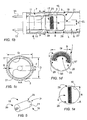
- FIG. 1a shows a cathode screen 15a for a cathode unit 5 according to a first embodiment. To the left is shown the cathode screen 15a in cross-section from the side and to the right is shown the cathode screen 15a incorporated in a fluorescent tube body 3.
- the cathode screen 15a has been designed with two side walls 2 becoming incident to the centre line CL.
- a space 4 created between the cathode screen 15a and the fluorescent tube body 3 in combination with a completely open second end 39 of the cathode screen 15a means that the through-flow is very effective for the removal of the said impurities.
- the assembly of the cathode screen 15a to a fixing device 17 is simplified by the flat surface that is obtained. Similarly, insertion of the cathode unit 5 in the fluorescent tube body 3 of the fluorescent tube 1 during the manufacture of the fluorescent tube 1 is made simpler. A greater tolerance is obtained in the direction u-u, which contributes to more reliable insertion during assembly, without the cathode screen 15a coming into contact with the fluorescent tube body 3.
- Figure 1b shows a longitudinal section of one end of the fluorescent tube body 3 of the fluorescent tube 1 comprising the cathode unit 5 according to a second embodiment.
- the fluorescent tube body 3, such as a glass bulb, of the fluorescent tube 1 is connected at its respective end in a conventional way by a foot 7 which also serves as a means of support for a power supply device 11 supporting an electrode 9.
- the power supply device 11 is arranged to make an electrical connection between the electrode 9 and a contact 13 arranged at one end of the fluorescent tube 1, which contact can be connected to a power supply unit (not shown).
- the electrode 9 is partially surrounded by the cathode screen 15.
- the cathode screen 15 is supported by a fixing device 17, such as a metal strut, and is electrically insulated from the electrode 9 by means of the electrically-insulating foot 7.
- a first end 19 of the cathode screen 15 comprises a central opening 21.
- the first end 19 faces towards the discharge, that is to say towards the other end of the fluorescent tube 1 and the electrode (not shown) arranged there.
- the central opening 21 has a diameter d of 3-8 mm, preferably 5-7 mm, which has been shown by experiment to be the most efficient size of the central opening 21 in cathode screens 15 for narrow fluorescent tubes, such as fluorescent tubes with a diameter of 16 mm.
- the first end 19 is shaped with a rounded-off part 25 to make easier the insertion of the cathode unit 5 into the fluorescent tube body 3 during manufacture.
- the fluorescent tube body 3 of the fluorescent tube 1 is coated on the inside with a phosphor powder 27.
- the rounded-off part 25 means that the cathode unit 5 can be assembled in the fluorescent tube body 3 in a reliable way without the coating, such as the phosphor powder 27, being scraped off the inside of the fluorescent tube body 3.
- FIG. 1c shows a cross section A-A of the cathode unit 5 shown in Figure 1b .
- the cathode screen 15 is manufactured with a thin material thickness in order to create as large a space as possible inside the cathode screen 15.
- the outer side of the cathode screen 15, viewed in the longitudinal direction of the cathode screen 15, follows a straight line L parallel to the longitudinal axis of the fluorescent tube body 3 and a centre line CL.
- the outer side or the external diameter D of the cathode screen 15 is smaller than the internal diameter Gi of the fluorescent tube body 3, so that a gap S is created of 1-4 mm in size, preferably 2-3 mm. In this way, the maximal amount of emitter material 23 can be applied on the electrode 9 along the section B between the fixing points 29 of the electrode 9.
- the cathode screen 15 is manufactured in one piece, which means that the cathode screen 15 can be produced in a single stage.
- the cathode screen 15 is formed in this embodiment by pressing the metal, such as iron or nickel, in a pressing tool (not shown).
- the manufacturing process means that small components do not need to be assembled together. This has great advantages.
- Manufacturing the cathode screen 15 in one piece is cost-effective and improves the operating characteristics of the cathode screen 15 which prolongs the life of the fluorescent tube 1.
- Many small components assembled together to form a unit can increase the danger of malfunction.
- the danger of malfunction is relatively great on account of these small components.
- the present cathode screen 15 eliminates such malfunctions.
- Figure 1d shows schematically the layout of an electrode 9 and its arrangement in relation to a cathode screen 15" according to a third embodiment.
- the emitter material 23 is applied along the section B between the fixing points 29 of the electrode 9.
- the fixing points 29 are arranged simply adjacent to the inner side 33 of the cylinder-shaped cathode screen 15", as the cathode screen 15" does not have a bottom. In this way, a large quantity of emitter material 23 can be fitted on the electrode 9 surrounded by the cathode screen 15".
- the cathode unit 5 shown in Figure 1b is shown in Figure 1e , where the electrode 9 has a straight section between the fixing points 29.
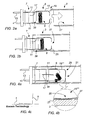
- Figures 2a and 2b show the insertion of the cathode unit 5 in Figure 1a into a fluorescent tube body 3 with phosphor powder 27 applied on the inside of the fluorescent tube body 3.
- the rounded-off part 25 of the cathode screen 15 means that the insertion of the cathode unit 5 is simplified, while at the same time the phosphor powder 27 is not damaged. In this way, the phosphor powder 27 remains intact and the manufacture of the fluorescent tube 1 is cost-effective.
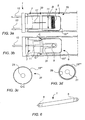
- FIGs 3a-3c show a cathode screen 15"' according to a fourth embodiment.
- Figure 3b shows the cathode screen 15"' in side view
- Figure 3c shows the cathode screen 15"' in Figure 3b in a view C-C.
- the reference numbers correspond to those shown in the previous figures.
- the cathode screen 15"' is designed with two slots 31 within the area of the power supply device 11. It has been shown by experiment, that the slot 31 does not significantly affect the escape of emitter material 23 from the interior of the cathode screen 15"'.
- the fixing points 29 can be positioned slightly out in the respective slot 31, whereby additional emitter material 23 can be applied on the electrode 9. In this way, a prolonged life of the fluorescent tube 1 is achieved.
- the cathode screen 15"' is displaced from its position somewhat and is bent downwards, which is shown in exaggerated form in Figure 3a in order to clarify the situation, the electrode 9 does not come into contact with the cathode screen 15"' but reaches a position within the area of the slot 31, and thus remains electrically insulated from the electrode 9. This means that the operational reliability of the fluorescent tube 1 is increased. In this way, the electrode 9 can be made longer without the risk of shorting and can thereby also be given additional emitter material 23, whereby the life of the fluorescent tube is increased.
- Figure 3d shows a cathode screen 15"" according to an example falling outside the scope of the claims, in which an electrically insulating material 35, such a porcelain or enamel, is coated on the inner side 33 of the cathode screen 15"". In this way, in the event of it coming into contact with the cathode screen 15"", the electrode 9 is still electrically insulated from this.
- FIG. 4a shows schematically how the electrode 9 has burnt off and in this way heated up the cathode screen 15"".
- Figure 4b shows an enlarged section of the contact point between the fluorescent tube body 3 and the cathode screen 15"".
- a heat-insulating material 37 may, in an example falling outside the scope of the claims be applied to the cathode screen 15"", which material can be glass, and prevents to a great extent the transmission of heat from the heated-up cathode screen 15"" to the fluorescent tube body 3, whereby the danger of the fluorescent tube 1 shattering and falling out of its mounting (not shown) is eliminated.
- the rounded-off part 25 of the cathode screen 15"” increases the contact surface between the cathode screen 15"” and the fluorescent tube body 3, which means that the heat is distributed over a large area.
- Figure 4c shows a cathode screen according to known technology, where a sharp corner exudes heat over a very small area, which results in a great danger of the fluorescent tube shattering.
- Impurities in the fluorescent tube often consist of the normal components of air, for example oxygen, nitrogen, carbon dioxide, impurities of the hydrocarbon type and decomposition products from the emitter material, for example carbon dioxide. Impurities within the fluorescent tube 1 can impair the function and life of the fluorescent tube 1. Therefore various types of pumping processes are used to remove different gases, for example to remove decomposition products from the emitter material 23. Impurities, which principally occur in molecular form, have the ability to absorb energy from processes in the discharge which have the function of ensuring an effective ionisation of the emitter material 23. Any impurities thereby also result in a deterioration in the return of emitter material 23 to the electrode 9. Certain end products from the impurities have a similar negative effect on the emission capabilities of the cathode unit 5.
- a method for pumping, gas filling and sealing of a fluorescent tube 1 is carried out by the fluorescent tube 1 being provided with a pumping pipe (not shown) at each end. A vacuum is created at one end, while a lamp-filling gas is supplied at the other end, which gas "flushes out” the said decomposition products from the emitter material 23.
- the emitter material 23 on the electrode 9 comprises carbonates that must not remain in the fluorescent tube 1 when this is sealed. Approximately a third of the weight of the emitter material 23 is converted to gas and removed in an efficient way.
- One way of achieving an effective pumping process is so-called "argon rinsing" in which argon is applied in the fluorescent tube 1 repeatedly.
- the completely open second end 39 also means that the manufacturing process is simplified.
- the cathode unit 5 can be manufactured from a cylinder blank made from a metal strip, which blank is cut off into suitable lengths.
- the first end 19 of each cathode screen 15 that is produced is bent so that a rounded-off section 25 is provided, drawing the end together with a central opening 21.
- the first end 19 can also comprise flaps 41 that are bent to draw the end together.
- Such a cathode screen 15 according to a sixth embodiment is shown in Figure 5 .
- a large amount of emitter material 23 on the electrode 9 has a positive effect on the life of the fluorescent tube 1. It is desirable that the degree of ionisation attains the highest possible value, within the whole of the area where there is a high occurrence of emitter material.
- the design of the present cathode unit 5 means that a maximal amount of emitter material 23 can be applied on the electrode 9 and that vaporised and sputtered emitter material can be ionised to a high degree.
- a fluorescent tube 1 is achieved with a longer life than with known technology.
- the cathode screen 15 itself is arranged at the least possible distance from the wall of the fluorescent tube body 1.
- the fixing points 29 can be arranged at a maximal distance from each other. In this way, as much emitter material 23 as possible can be accommodated between the fixing points 29.
- a fluorescent tube 1, as shown in Figure 6 is manufactured according to a method that is characterised by the stages: pressing the said cathode screen 15 in one piece, with the first end 19 being shaped with a rounded-off part 25; welding the cathode screen 15 to the fixing device 17 that is attached to the foot 7; assembling the said cathode screen 15 to the said foot 7; inserting the said cathode unit 5 in the said fluorescent tube body 3; removal of decomposition products of the emitter material 23 by pumping; and sealing the fluorescent tube 1 when all the decomposition products have been removed from the fluorescent tube 1.
- the cathode screen 15 can be manufactured from materials other than metal, for example a material that does not conduct electricity, coated for example by enamel or glass. Alternatively, the cathode screen can be manufactured completely of glass.
- the fixing device 17 can similarly be constructed to be heat resistant in order to avoid the abovementioned bending downwards of the cathode screen 15.
- the central opening 21 can also be a different shape, for example elliptical or angular.
- the cathode screen 15 itself can also have an angular or tapering cross section.
Landscapes
- Engineering & Computer Science (AREA)
- Manufacturing & Machinery (AREA)
- Discharge Lamp (AREA)
- Vessels And Coating Films For Discharge Lamps (AREA)
Claims (8)
- Kathodeneinheit für den Einbau in einen Leuchtstoffröhrenkörper (3), der einer Leuchtstoffröhre (1) gehört, welche Kathodeneinheit (5) einen Kathodenschirm (15a, 15, 15'-15"") umfasst, der vollständig aus reinem Metall hergestellt ist, das teilweise eine Elektrode (9) umgibt, die vom Kathodenschirm (15) elektrisch isoliert ist, wobei eine Stromversorgungsvorrichtung (11) dazu ausgelegt ist, eine elektrische Verbindung zwischen der Elektrode (9) und einem Kontakt (13) herzustellen, welcher Kathodenschirm (15) ein erstes dem Austritt zugewandtes Ende (19), welches erste Ende (19) eine mittige Öffnung (21) umfasst, und ein zweites dem Kontakt (13) zugewandtes Ende (39) umfasst, wobei das erste Ende (19) des Kathodenschirms (15a, 15, 15'-15"") mit einem abgerundeten Teil (25) ausgeführt ist, um das Einsetzen der Kathodeneinheit (5) in den Leuchtstoffröhrenkörper (3) zu erleichtern, dadurch gekennzeichnet, dass die mittige Öffnung (21) einen Durchmesser (d) von 3-8 mm, vorzugsweise 5-7 mm, zum Auffangen und Festhalten einer großen Anzahl von positiv geladenen Partikeln für eine erhebliche Zeit in der Nähe der heißen Stelle aufweist, was zur Rückkehr des Emittermaterials zur Elektrode beiträgt.
- Kathodeneinheit nach Anspruch 1, dadurch gekennzeichnet, dass der Kathodenschirm (15a) mit zumindest einer im Wesentlichen auf eine Mittellinie (CL) einfallenden Seitenwand (2) ausgeführt ist.
- Kathodeneinheit nach Anspruch 1 oder 2, dadurch gekennzeichnet, dass der Kathodenschirm (15a, 15, 15'-15"") in einem Stück hergestellt ist.
- Kathodeneinheit nach einem der vorhergehenden Ansprüche, dadurch gekennzeichnet, dass der Kathodenschirm (15a, 15, 15'-15"") mit zumindest einem Schlitz (31) in dem Bereich für die Stromversorgungsvorrichtung (11) ausgeführt ist.
- Kathodeneinheit nach einem der vorhergehenden Ansprüche, dadurch gekennzeichnet, dass die Außenseite des Kathodenschirms (15a, 15, 15'-15""), in der Längsrichtung des Kathodenschirms (15) gesehen, einer geraden Linie L folgt, die zur Längsachse des Leuchtstoffröhrenkörpers im Wesentlichen parallel ist.
- Kathodeneinheit nach einem der vorhergehenden Ansprüche, dadurch gekennzeichnet, dass das zweite Ende (39) des Kathodenschirms (15a, 15, 15'-15"") vollständig offen ist.
- Verfahren zur Herstellung einer Leuchtstoffröhre (1), umfassend einen Leuchtstoffröhrenkörper (3), eine Kathodeneinheit (5), welche Kathodeneinheit (5) einen Kathodenschirm (15a, 15, 15'-15"") umfasst, der vollständig aus reinem Metall hergestellt ist, das teilweise eine mit Emittermaterial (23) versehene Elektrode (9) umgibt, welche Elektrode (9) vom Kathodenschirm (15) elektrisch isoliert ist, eine an einem Fuß (7) befestigte Stromversorgungsvorrichtung (11), welche Stromversorgungsvorrichtung (11) dazu ausgelegt ist, eine elektrische Verbindung zwischen der Elektrode (9) und einem Kontakt (13) herzustellen, welcher Kathodenschirm (15) ein erstes dem Austritt zugewandtes Ende (19), welches erste Ende eine mittige Öffnung (21) umfasst, die einen Durchmesser (d) von 3-8 mm, vorzugsweise 5-7 mm, aufweist, und ein zweites dem Kontakt (13) zugewandtes Ende (39) umfasst, gekennzeichnet durch die Stufen:- Drücken des Kathodenschirms in einem Stück mit dem ersten Ende (19), das mit einem abgerundeten Teil (25) ausgebildet ist;- Schweißen des Kathodenschirms (15a, 15, 15'-15"") auf einer auf dem Fuß (7) befestigten Fixiervorrichtung (17);- Einsetzen der Kathodeneinheit (5) in den Leuchtstoffröhrenkörper (3);- Entfernen von Abbauprodukten des Emittermaterials (23) durch das Pumpen; und- Dichten der Leuchtstoffröhre (1), wenn alle Abbauprodukte von der Leuchtstoffröhre (1) entfernt worden sind.
- Leuchtstoffröhre, die zumindest eine Kathodeneinheit (5) nach einem der vorhergehenden Ansprüche 1 bis 6 umfasst.
Applications Claiming Priority (3)
| Application Number | Priority Date | Filing Date | Title |
|---|---|---|---|
| SE0201096 | 2002-04-11 | ||
| SE0201096A SE524397C2 (sv) | 2002-04-11 | 2002-04-11 | Katodenhet för lysrör och förfarande för tillverkning av lysrör |
| PCT/SE2003/000548 WO2003088307A1 (en) | 2002-04-11 | 2003-04-04 | Homogeneous cathode unit |
Publications (2)
| Publication Number | Publication Date |
|---|---|
| EP1493174A1 EP1493174A1 (de) | 2005-01-05 |
| EP1493174B1 true EP1493174B1 (de) | 2014-05-14 |
Family
ID=20287554
Family Applications (1)
| Application Number | Title | Priority Date | Filing Date |
|---|---|---|---|
| EP03717842.3A Expired - Lifetime EP1493174B1 (de) | 2002-04-11 | 2003-04-04 | Homogene kathodeneinheit |
Country Status (9)
| Country | Link |
|---|---|
| US (1) | US7394199B2 (de) |
| EP (1) | EP1493174B1 (de) |
| AU (1) | AU2003222541A1 (de) |
| DK (1) | DK1493174T3 (de) |
| ES (1) | ES2488637T3 (de) |
| NO (1) | NO336388B1 (de) |
| PT (1) | PT1493174E (de) |
| SE (1) | SE524397C2 (de) |
| WO (1) | WO2003088307A1 (de) |
Families Citing this family (2)
| Publication number | Priority date | Publication date | Assignee | Title |
|---|---|---|---|---|
| US6809468B1 (en) * | 2002-12-11 | 2004-10-26 | Light Sources, Inc. | Cathode with disintegration shield in a gas discharge lamp |
| SE530754C2 (sv) | 2006-01-25 | 2008-09-02 | Auralight Int Ab | Kompaktlysrörsanpassad katodskärm |
Citations (1)
| Publication number | Priority date | Publication date | Assignee | Title |
|---|---|---|---|---|
| JPS49142982U (de) * | 1973-04-07 | 1974-12-10 |
Family Cites Families (8)
| Publication number | Priority date | Publication date | Assignee | Title |
|---|---|---|---|---|
| SE435332B (sv) | 1979-11-07 | 1984-09-17 | Lumalampan Ab | Katodenhet for lysror |
| JPS62136746A (ja) * | 1985-12-11 | 1987-06-19 | Hitachi Ltd | 低圧水銀放電灯 |
| US5043627A (en) * | 1988-03-01 | 1991-08-27 | Fox Leslie Z | High-frequency fluorescent lamp |
| JP3400489B2 (ja) * | 1993-05-20 | 2003-04-28 | 東京電測株式会社 | 複合放電ランプ |
| US5686795A (en) * | 1995-10-23 | 1997-11-11 | General Electric Company | Fluorescent lamp with protected cathode to reduce end darkening |
| CN1132220C (zh) * | 1998-10-23 | 2003-12-24 | 皇家菲利浦电子有限公司 | 低压汞蒸气放电灯 |
| EP1155436B1 (de) * | 1999-11-24 | 2005-08-31 | Koninklijke Philips Electronics N.V. | Niederdruck-Quecksilberdampfentladungslampe |
| US6630787B2 (en) * | 2000-03-06 | 2003-10-07 | Koninklijke Philips Electronics N.V. | Low-pressure mercury-vapor discharge lamp having electrode shield carrying direct electric current |
-
2002
- 2002-04-11 SE SE0201096A patent/SE524397C2/sv not_active IP Right Cessation
-
2003
- 2003-04-04 DK DK03717842.3T patent/DK1493174T3/da active
- 2003-04-04 WO PCT/SE2003/000548 patent/WO2003088307A1/en not_active Ceased
- 2003-04-04 PT PT37178423T patent/PT1493174E/pt unknown
- 2003-04-04 ES ES03717842.3T patent/ES2488637T3/es not_active Expired - Lifetime
- 2003-04-04 EP EP03717842.3A patent/EP1493174B1/de not_active Expired - Lifetime
- 2003-04-04 US US10/510,445 patent/US7394199B2/en not_active Expired - Fee Related
- 2003-04-04 AU AU2003222541A patent/AU2003222541A1/en not_active Abandoned
-
2004
- 2004-11-10 NO NO20044902A patent/NO336388B1/no not_active IP Right Cessation
Patent Citations (1)
| Publication number | Priority date | Publication date | Assignee | Title |
|---|---|---|---|---|
| JPS49142982U (de) * | 1973-04-07 | 1974-12-10 |
Also Published As
| Publication number | Publication date |
|---|---|
| WO2003088307A1 (en) | 2003-10-23 |
| AU2003222541A1 (en) | 2003-10-27 |
| NO336388B1 (no) | 2015-08-10 |
| SE0201096L (sv) | 2003-10-12 |
| US7394199B2 (en) | 2008-07-01 |
| SE524397C2 (sv) | 2004-08-03 |
| ES2488637T3 (es) | 2014-08-28 |
| DK1493174T3 (da) | 2014-08-18 |
| US20060290283A1 (en) | 2006-12-28 |
| SE0201096D0 (sv) | 2002-04-11 |
| NO20044902L (no) | 2004-11-10 |
| EP1493174A1 (de) | 2005-01-05 |
| PT1493174E (pt) | 2014-07-24 |
Similar Documents
| Publication | Publication Date | Title |
|---|---|---|
| EP1298695B1 (de) | Gasentladungsröhre und diese verwendende Anzeigevorrichtung | |
| EP0596735B1 (de) | Bogenröhre mit einer Zündquelle | |
| KR20040103906A (ko) | 가스 방전관 | |
| US6426592B2 (en) | High-voltage discharge lamp with cylindrical member to mitigate thermal stress | |
| CN100565778C (zh) | 具有总体长度缩短的电弧管及其制造方法和低压汞灯 | |
| US6856091B2 (en) | Seal for ceramic metal halide discharge lamp chamber | |
| EP0556800B1 (de) | Gasentladungslampe mit Löschmechanismus am Ende der Lebensdauer | |
| US7394199B2 (en) | Homogeneous cathode unit | |
| CN1152411C (zh) | 用于气体放电的冷电极 | |
| AU6570480A (en) | Cathode unit for fluorescent tube | |
| US7633227B2 (en) | Discharge lamp with lamp base structure | |
| JP3275847B2 (ja) | 高圧金属蒸気放電灯 | |
| JP3217313B2 (ja) | 高圧放電ランプおよびその製造方法 | |
| EP1814139A1 (de) | An eine kompakte Leuchtstofflampe angepasster Kathodenschirm | |
| CN1307682C (zh) | 带有寿命终止结构的低压放电灯 | |
| US20060001380A1 (en) | Seal for ceramic discharge lamp arc tube | |
| CN1985349A (zh) | 制造具有各种形状和尺寸的外电极荧光灯的方法以及用于这种方法的玻璃管单元结构 | |
| JP7141692B2 (ja) | 放電灯の封止構造、および当該構造を備える放電灯 | |
| US20050140294A1 (en) | Cold cathode fluorescent lamp and method for forming the same | |
| JPS6193536A (ja) | X線管の陰極構体 | |
| WO2007075472A2 (en) | Backwound electrode coil for electric arc tube of ceramic metal halide lamp and method of manufacture | |
| JP3489679B2 (ja) | 蛍光ランプ装置 | |
| WO2004090935A2 (en) | Lamp assembly | |
| WO2006053018A2 (en) | Cathode unit for fluorescent lamps | |
| US20090273272A1 (en) | Multi-electrode fluorescent lamp tube |
Legal Events
| Date | Code | Title | Description |
|---|---|---|---|
| PUAI | Public reference made under article 153(3) epc to a published international application that has entered the european phase |
Free format text: ORIGINAL CODE: 0009012 |
|
| 17P | Request for examination filed |
Effective date: 20041021 |
|
| AK | Designated contracting states |
Kind code of ref document: A1 Designated state(s): AT BE BG CH CY CZ DE DK EE ES FI FR GB GR HU IE IT LI LU MC NL PT RO SE SI SK TR |
|
| AX | Request for extension of the european patent |
Extension state: AL LT LV MK |
|
| 17Q | First examination report despatched |
Effective date: 20110111 |
|
| REG | Reference to a national code |
Ref country code: DE Ref legal event code: R079 Ref document number: 60346188 Country of ref document: DE Free format text: PREVIOUS MAIN CLASS: H01J0061040000 Ipc: H01J0061100000 |
|
| RIC1 | Information provided on ipc code assigned before grant |
Ipc: H01J 61/10 20060101AFI20130927BHEP |
|
| GRAP | Despatch of communication of intention to grant a patent |
Free format text: ORIGINAL CODE: EPIDOSNIGR1 |
|
| INTG | Intention to grant announced |
Effective date: 20131204 |
|
| GRAS | Grant fee paid |
Free format text: ORIGINAL CODE: EPIDOSNIGR3 |
|
| GRAA | (expected) grant |
Free format text: ORIGINAL CODE: 0009210 |
|
| AK | Designated contracting states |
Kind code of ref document: B1 Designated state(s): AT BE BG CH CY CZ DE DK EE ES FI FR GB GR HU IE IT LI LU MC NL PT RO SE SI SK TR |
|
| REG | Reference to a national code |
Ref country code: GB Ref legal event code: FG4D |
|
| REG | Reference to a national code |
Ref country code: AT Ref legal event code: REF Ref document number: 668854 Country of ref document: AT Kind code of ref document: T Effective date: 20140615 |
|
| REG | Reference to a national code |
Ref country code: IE Ref legal event code: FG4D |
|
| REG | Reference to a national code |
Ref country code: DE Ref legal event code: R096 Ref document number: 60346188 Country of ref document: DE Effective date: 20140703 |
|
| REG | Reference to a national code |
Ref country code: PT Ref legal event code: SC4A Free format text: AVAILABILITY OF NATIONAL TRANSLATION Effective date: 20140714 |
|
| REG | Reference to a national code |
Ref country code: CH Ref legal event code: NV Representative=s name: HEPP WENGER RYFFEL AG, CH |
|
| REG | Reference to a national code |
Ref country code: DK Ref legal event code: T3 Effective date: 20140815 |
|
| REG | Reference to a national code |
Ref country code: ES Ref legal event code: FG2A Ref document number: 2488637 Country of ref document: ES Kind code of ref document: T3 Effective date: 20140828 |
|
| REG | Reference to a national code |
Ref country code: SE Ref legal event code: TRGR |
|
| REG | Reference to a national code |
Ref country code: NL Ref legal event code: T3 |
|
| REG | Reference to a national code |
Ref country code: GR Ref legal event code: EP Ref document number: 20140401588 Country of ref document: GR Effective date: 20140930 |
|
| PG25 | Lapsed in a contracting state [announced via postgrant information from national office to epo] |
Ref country code: CY Free format text: LAPSE BECAUSE OF FAILURE TO SUBMIT A TRANSLATION OF THE DESCRIPTION OR TO PAY THE FEE WITHIN THE PRESCRIBED TIME-LIMIT Effective date: 20140514 |
|
| PG25 | Lapsed in a contracting state [announced via postgrant information from national office to epo] |
Ref country code: SK Free format text: LAPSE BECAUSE OF FAILURE TO SUBMIT A TRANSLATION OF THE DESCRIPTION OR TO PAY THE FEE WITHIN THE PRESCRIBED TIME-LIMIT Effective date: 20140514 Ref country code: CZ Free format text: LAPSE BECAUSE OF FAILURE TO SUBMIT A TRANSLATION OF THE DESCRIPTION OR TO PAY THE FEE WITHIN THE PRESCRIBED TIME-LIMIT Effective date: 20140514 Ref country code: EE Free format text: LAPSE BECAUSE OF FAILURE TO SUBMIT A TRANSLATION OF THE DESCRIPTION OR TO PAY THE FEE WITHIN THE PRESCRIBED TIME-LIMIT Effective date: 20140514 Ref country code: RO Free format text: LAPSE BECAUSE OF FAILURE TO SUBMIT A TRANSLATION OF THE DESCRIPTION OR TO PAY THE FEE WITHIN THE PRESCRIBED TIME-LIMIT Effective date: 20140514 Ref country code: BE Free format text: LAPSE BECAUSE OF FAILURE TO SUBMIT A TRANSLATION OF THE DESCRIPTION OR TO PAY THE FEE WITHIN THE PRESCRIBED TIME-LIMIT Effective date: 20140514 |
|
| REG | Reference to a national code |
Ref country code: DE Ref legal event code: R097 Ref document number: 60346188 Country of ref document: DE |
|
| PLBE | No opposition filed within time limit |
Free format text: ORIGINAL CODE: 0009261 |
|
| STAA | Information on the status of an ep patent application or granted ep patent |
Free format text: STATUS: NO OPPOSITION FILED WITHIN TIME LIMIT |
|
| 26N | No opposition filed |
Effective date: 20150217 |
|
| REG | Reference to a national code |
Ref country code: DE Ref legal event code: R097 Ref document number: 60346188 Country of ref document: DE Effective date: 20150217 |
|
| PG25 | Lapsed in a contracting state [announced via postgrant information from national office to epo] |
Ref country code: SI Free format text: LAPSE BECAUSE OF FAILURE TO SUBMIT A TRANSLATION OF THE DESCRIPTION OR TO PAY THE FEE WITHIN THE PRESCRIBED TIME-LIMIT Effective date: 20140514 |
|
| PGRI | Patent reinstated in contracting state [announced from national office to epo] |
Ref country code: BE Effective date: 20150507 |
|
| PG25 | Lapsed in a contracting state [announced via postgrant information from national office to epo] |
Ref country code: LU Free format text: LAPSE BECAUSE OF FAILURE TO SUBMIT A TRANSLATION OF THE DESCRIPTION OR TO PAY THE FEE WITHIN THE PRESCRIBED TIME-LIMIT Effective date: 20150404 Ref country code: MC Free format text: LAPSE BECAUSE OF FAILURE TO SUBMIT A TRANSLATION OF THE DESCRIPTION OR TO PAY THE FEE WITHIN THE PRESCRIBED TIME-LIMIT Effective date: 20140514 |
|
| REG | Reference to a national code |
Ref country code: IE Ref legal event code: MM4A |
|
| REG | Reference to a national code |
Ref country code: FR Ref legal event code: PLFP Year of fee payment: 14 |
|
| PG25 | Lapsed in a contracting state [announced via postgrant information from national office to epo] |
Ref country code: IE Free format text: LAPSE BECAUSE OF NON-PAYMENT OF DUE FEES Effective date: 20150404 |
|
| REG | Reference to a national code |
Ref country code: FR Ref legal event code: PLFP Year of fee payment: 15 |
|
| PG25 | Lapsed in a contracting state [announced via postgrant information from national office to epo] |
Ref country code: BG Free format text: LAPSE BECAUSE OF FAILURE TO SUBMIT A TRANSLATION OF THE DESCRIPTION OR TO PAY THE FEE WITHIN THE PRESCRIBED TIME-LIMIT Effective date: 20140514 Ref country code: HU Free format text: LAPSE BECAUSE OF FAILURE TO SUBMIT A TRANSLATION OF THE DESCRIPTION OR TO PAY THE FEE WITHIN THE PRESCRIBED TIME-LIMIT; INVALID AB INITIO Effective date: 20030404 |
|
| PG25 | Lapsed in a contracting state [announced via postgrant information from national office to epo] |
Ref country code: TR Free format text: LAPSE BECAUSE OF FAILURE TO SUBMIT A TRANSLATION OF THE DESCRIPTION OR TO PAY THE FEE WITHIN THE PRESCRIBED TIME-LIMIT Effective date: 20140514 |
|
| REG | Reference to a national code |
Ref country code: FR Ref legal event code: PLFP Year of fee payment: 16 |
|
| PGFP | Annual fee paid to national office [announced via postgrant information from national office to epo] |
Ref country code: GB Payment date: 20180329 Year of fee payment: 16 Ref country code: NL Payment date: 20180314 Year of fee payment: 16 |
|
| PGFP | Annual fee paid to national office [announced via postgrant information from national office to epo] |
Ref country code: BE Payment date: 20180314 Year of fee payment: 16 Ref country code: FR Payment date: 20180326 Year of fee payment: 16 Ref country code: GR Payment date: 20180312 Year of fee payment: 16 |
|
| PGFP | Annual fee paid to national office [announced via postgrant information from national office to epo] |
Ref country code: DK Payment date: 20180410 Year of fee payment: 16 Ref country code: DE Payment date: 20180320 Year of fee payment: 16 Ref country code: ES Payment date: 20180503 Year of fee payment: 16 Ref country code: CH Payment date: 20180416 Year of fee payment: 16 Ref country code: FI Payment date: 20180410 Year of fee payment: 16 Ref country code: PT Payment date: 20180402 Year of fee payment: 16 |
|
| PGFP | Annual fee paid to national office [announced via postgrant information from national office to epo] |
Ref country code: AT Payment date: 20180326 Year of fee payment: 16 Ref country code: IT Payment date: 20180420 Year of fee payment: 16 |
|
| PGFP | Annual fee paid to national office [announced via postgrant information from national office to epo] |
Ref country code: SE Payment date: 20180411 Year of fee payment: 16 |
|
| REG | Reference to a national code |
Ref country code: DE Ref legal event code: R119 Ref document number: 60346188 Country of ref document: DE |
|
| REG | Reference to a national code |
Ref country code: CH Ref legal event code: PL |
|
| REG | Reference to a national code |
Ref country code: DK Ref legal event code: EBP Effective date: 20190430 |
|
| REG | Reference to a national code |
Ref country code: SE Ref legal event code: EUG |
|
| REG | Reference to a national code |
Ref country code: NL Ref legal event code: MM Effective date: 20190501 |
|
| REG | Reference to a national code |
Ref country code: AT Ref legal event code: MM01 Ref document number: 668854 Country of ref document: AT Kind code of ref document: T Effective date: 20190404 |
|
| REG | Reference to a national code |
Ref country code: BE Ref legal event code: MM Effective date: 20190430 |
|
| GBPC | Gb: european patent ceased through non-payment of renewal fee |
Effective date: 20190404 |
|
| PG25 | Lapsed in a contracting state [announced via postgrant information from national office to epo] |
Ref country code: AT Free format text: LAPSE BECAUSE OF NON-PAYMENT OF DUE FEES Effective date: 20190404 Ref country code: SE Free format text: LAPSE BECAUSE OF NON-PAYMENT OF DUE FEES Effective date: 20190405 Ref country code: GB Free format text: LAPSE BECAUSE OF NON-PAYMENT OF DUE FEES Effective date: 20190404 Ref country code: FI Free format text: LAPSE BECAUSE OF NON-PAYMENT OF DUE FEES Effective date: 20190404 Ref country code: DE Free format text: LAPSE BECAUSE OF NON-PAYMENT OF DUE FEES Effective date: 20191101 Ref country code: PT Free format text: LAPSE BECAUSE OF NON-PAYMENT OF DUE FEES Effective date: 20191004 Ref country code: NL Free format text: LAPSE BECAUSE OF NON-PAYMENT OF DUE FEES Effective date: 20190501 Ref country code: LI Free format text: LAPSE BECAUSE OF NON-PAYMENT OF DUE FEES Effective date: 20190430 Ref country code: CH Free format text: LAPSE BECAUSE OF NON-PAYMENT OF DUE FEES Effective date: 20190430 |
|
| PG25 | Lapsed in a contracting state [announced via postgrant information from national office to epo] |
Ref country code: GR Free format text: LAPSE BECAUSE OF NON-PAYMENT OF DUE FEES Effective date: 20191105 Ref country code: FR Free format text: LAPSE BECAUSE OF NON-PAYMENT OF DUE FEES Effective date: 20190430 Ref country code: BE Free format text: LAPSE BECAUSE OF FAILURE TO SUBMIT A TRANSLATION OF THE DESCRIPTION OR TO PAY THE FEE WITHIN THE PRESCRIBED TIME-LIMIT Effective date: 20190430 |
|
| PG25 | Lapsed in a contracting state [announced via postgrant information from national office to epo] |
Ref country code: DK Free format text: LAPSE BECAUSE OF NON-PAYMENT OF DUE FEES Effective date: 20190430 Ref country code: IT Free format text: LAPSE BECAUSE OF NON-PAYMENT OF DUE FEES Effective date: 20190404 |
|
| REG | Reference to a national code |
Ref country code: ES Ref legal event code: FD2A Effective date: 20200828 |
|
| PG25 | Lapsed in a contracting state [announced via postgrant information from national office to epo] |
Ref country code: ES Free format text: LAPSE BECAUSE OF NON-PAYMENT OF DUE FEES Effective date: 20190405 |