EP1491970B1 - Image forming apparatus - Google Patents
Image forming apparatus Download PDFInfo
- Publication number
- EP1491970B1 EP1491970B1 EP04014879A EP04014879A EP1491970B1 EP 1491970 B1 EP1491970 B1 EP 1491970B1 EP 04014879 A EP04014879 A EP 04014879A EP 04014879 A EP04014879 A EP 04014879A EP 1491970 B1 EP1491970 B1 EP 1491970B1
- Authority
- EP
- European Patent Office
- Prior art keywords
- toner
- latent image
- bearing member
- image bearing
- image forming
- Prior art date
- Legal status (The legal status is an assumption and is not a legal conclusion. Google has not performed a legal analysis and makes no representation as to the accuracy of the status listed.)
- Active
Links
Images


Classifications
-
- G—PHYSICS
- G03—PHOTOGRAPHY; CINEMATOGRAPHY; ANALOGOUS TECHNIQUES USING WAVES OTHER THAN OPTICAL WAVES; ELECTROGRAPHY; HOLOGRAPHY
- G03G—ELECTROGRAPHY; ELECTROPHOTOGRAPHY; MAGNETOGRAPHY
- G03G21/00—Arrangements not provided for by groups G03G13/00 - G03G19/00, e.g. cleaning, elimination of residual charge
- G03G21/16—Mechanical means for facilitating the maintenance of the apparatus, e.g. modular arrangements
- G03G21/18—Mechanical means for facilitating the maintenance of the apparatus, e.g. modular arrangements using a processing cartridge, whereby the process cartridge comprises at least two image processing means in a single unit
- G03G21/1803—Arrangements or disposition of the complete process cartridge or parts thereof
- G03G21/1817—Arrangements or disposition of the complete process cartridge or parts thereof having a submodular arrangement
-
- G—PHYSICS
- G03—PHOTOGRAPHY; CINEMATOGRAPHY; ANALOGOUS TECHNIQUES USING WAVES OTHER THAN OPTICAL WAVES; ELECTROGRAPHY; HOLOGRAPHY
- G03G—ELECTROGRAPHY; ELECTROPHOTOGRAPHY; MAGNETOGRAPHY
- G03G21/00—Arrangements not provided for by groups G03G13/00 - G03G19/00, e.g. cleaning, elimination of residual charge
- G03G21/06—Eliminating residual charges from a reusable imaging member
- G03G21/08—Eliminating residual charges from a reusable imaging member using optical radiation
Description
- The present invention relates to an image forming apparatus performing electrostatic copying processes for use in copiers, facsimile machines, printers, etc. and more particularly, to an image forming apparatus having the features of the preamble of claim 1..
- Recently, color image forming apparatuses using electrophotography have been widely diffused. In addition, almost all the images printed by these apparatuses are digitized before printing and thus a need for an image forming apparatus capable of printing further fine color images does exist. It has been attempted to achieve images having a high resolution and a fine gradation using a toner having a high circularity and a small particle diameter.
- It is certain that a toner having a high circularity and a small particle diameter is exactly transferred and therefore suitable for obtaining a super fine image. However, especially toner particles having a high circularity tend to sneak into a space between the cleaning blade used as a cleaner and a photoconductor. Therefore, it is difficult to remove the remaining toner particles on the photoconductor. Thus, the remaining toner particles tend to be transferred to a charger, resulting in contamination of the charging members such as the charging roller, thereby forming faulty images having, for example, uneven density and background development due to uneven charging.
- Published unexamined Japanese patent application (hereinafter referred to as JOP.)
No. 2002-6710 - JOP. No. 2000-276024 discloses a cleaner which removes remaining toner particles on a movable body. In this disclosure, a discharging means having a roller form is provided at an upstream side from the movable body relative to the moving direction thereof to apply a volt alternating current while contacting with the movable body. Also a cleaner having a blade is provided at a downstream side from the movable body. The discharging means discharges the movable body and the remaining toner thereon so as to clear the movable body of the remaining toner. In JOP. 2002-351279, to remove remaining toner particles on the photoconductor, a fur brush made of a conductive fabric is provided. In addition, a conductive collecting roller which applies a voltage while contacting the fur brush is provided. The remaining toner particles on the photoconductor drum are captured by the fur brush which rotates while abrading the photoconductor and guided to the conductive roller as the fur brush rotates. Then the remaining toner is electrostatically attracted by the conductive collecting roller due to a voltage applied thereto. However, the apparatus has a drawback of the cost increase because a powder supply means and so on have to be provided to apply the voltage.
- Further, JOP. No. 10-49017 discloses an image forming apparatus including an irradiator, which is provided at the upstream side of a cleaning blade relative to the rotation direction of an amorphous silicone photoconductor drum. This irradiator irradiates a photoconductor drum with light before cleaning to weaken the electrostatic force of toner particles remaining on the photoconductor drum. Then the toner particles remaining on the photoconductor drum are collected by a magnet roller and the collected toner particles are recycled, re-supplied and used for developing a latent image on the photoconductor. However, the technology disclosed is to prevent the photoconductor from deteriorating due to the abrasion caused by a single component magnetic toner held on a magnet roller. Therefore, it is difficult to apply this technology to a double component developer for use in forming color images.
-
EP 1 286 225 A2 relates to a developing assembly, process cartridge and image-forming method. In a developing assembly, a process cartridge and an image-forming method, a specific developer and a specific developer-carrying member are used in combination. The developer comprises toner particles containing at least a binder resin and a colorant, and conductive fine particles; the toner particles having a Circularity a of less than 0.970 as found from the following expression: Circularity a = L0/L; where L0 represents the circumferential length of a circle having the same projected area as a particle image, and L represents the circumferential length of a projected image of a particle. The developer-carrying member has at least a substrate and a resin coat layer formed on the substrate; the resin coat layer containing at least a coat layer binder resin and a positively chargeable material. -
US 2002/0106219 A1 relates to an image forming apparatus and process cartridge. An image forming apparatus is disclosed in which an electrophotographic photosensitive member is rotated at a peripheral speed of 150 mm/second or more and a specific toner is used. The toner has a weight-average particle diameter from 5 to 12 µm, and of the toner having a circle-equivalent diameter of 3 µm or more, particles with a circularity of 0.900 or more are present at a rate of 90% or more in a number-based cumulative valve. The toner also satisfies one of two sets of conditions which are defined by the relationship between a cut rate and a weight-average particle diameter and the relationship between a number-based cumulative valve and a weight-average particle diameter. The cut rate % is represented by the expression: Z=(1-B/A)x100; wherein A is a concentration of all the measured particles and B is a concentration of the measured particles whose circle-equivalent diameters are 3 µm or more. -
JP 10-049017 A -
US 4,571,066 relates to an electrophotographic copying apparatus including method of formation of toner transport grid used as a part of drum cleaning system. A cleaning system for a photoconductive drum in an electrographic copying apparatus is provided by appropriate utilization of the surface charging and discharging components which are already provided adjacent the path of movement of the rotating surface of the drum. An electrostatic grid is formed on a non-image portion of the surface of the drum to carry the residual toner and carrier back to the developing station. The residual toner is physically moved from the image bearing segment of the drum surface to the non-image bearing segment by means of a compliant roller member manipulated in a controlled fashion relative to the movement of the drum. Also, much of the residual toner which accumulates on the compliant member during this latter procedure is moved therefrom to the non-image bearing segment of the drum and held there by electrostatic attraction to the grid on the non-image bearing portion. The residual toner is removed from the non-image bearing drum segment by appropriate biasing of the development roller which is used initially to apply the toner to the surface of the drum. -
US 6,295,438 B1 relates to a method and apparatus for forming an image capable of supplying a proper amount of a lubricant to each image forming section. An image forming apparatus including a plurality of image forming sections each having an electrostatic latent image bearing member to form a latent image on its surface, a charging device to uniformly charge the electrostatic latent image bearing member, a developing device to develop the electrostatic latent image formed on the electrostatic latent image bearing member into a visible image and a cleaning device to remove developer adhered to the electrostatic latent image bearing member. The image forming sections are disposed in series in close proximity to or contacting a transfer sheet conveying belt spanned rotatively and are configured to differentiate an amount of a lubricant to be supplied to the surface of each electrostatic latent image bearing member such that at least one image forming section is differentiated from other image forming sections. -
US 6,269,228 B 1 relates to a method and apparatus for image forming performing improved cleaning and discharging operations on image forming associated members. An image forming apparatus includes an image carrying member, an intermediate transfer member, a charging member, a transfer mechanism, a discharging member, a direct current voltage source, and a direct current voltage controller. The intermediate transfer member is deposited at a position facing and in contact with the image carrying member rotatably carrying a toner image on a rotating surface, and receives the toner image therefrom during a first transfer operation. The charging member applies a charge to the intermediate transfer member to cause an electric field around a region where the image carrying member and the intermediate transfer member contact with each other, where the electric field generates a force for initiating the first transfer operation. The transfer mechanism performs a second transfer operation for transferring the toner image from the intermediate transfer member to a transfer sheet. The discharging member performs a discharging operation for discharging the charge remaining on the intermediate transfer member with contacting the intermediate transfer member after a completion of the second transfer operation. The direct current voltage source applies a direct current voltage to the discharging member to cause the discharging member to perform the discharging operation. The direct current voltage controller controls the direct current voltage in accordance with a volume resistivity of the intermediate transfer member. -
US 6,295,437 B1 relates to an apparatus and method for forming an image using a developing device capable of obtaining a high quality image. An image forming apparatus includes a latent image bearing member to bear an electrostatic latent image, and a developer bearing member to bear a developer, in which the electrostatic latent image is formed on the latent image bearing member by first uniformly charging the latent image bearing member and then by performing an optical writing operation. The electrostatic latent image is visualized by supplying the developer borne on the developer bearing member to the latent image bearing member. A lubricant for reducing a friction coefficient of a surface of the latent image bearing member is supplied to the latent image bearing member and the lubricant has a charging polarity opposite to that of the developer. The friction coefficient of the latent image bearing member is maintained such that adhering of the developer to a background part of the latent image is prevented as a result of supplying the lubricant to the latent image bearing member. The lubricant, which includes a silicone resin, is supplied to the latent image bearing member such that the friction coefficient of the surface of the latent image bearing member is from about 0.1 to about 0.4. The friction coefficient of the surface of the latent image bearing member is set such that a cleaning device to remove a residual developer on the surface of the latent image bearing member is prevented from being dragged by the latent image bearing member by decreasing a contact resistance between the cleaning device and the surface of the latent image bearing member. - Because of these reasons, the need exists for an image forming apparatus capable of producing further fine color images without using a complicated device.
- It is a general object of the present invention to provide an improved and useful image forming apparatus in which the above-mentioned problems are eliminatated.
- In order to achieve the above-mentioned object, there is provided an image forming apparatus according to claim 1.
- Advantageous embodiments are defined by the dependent claims.
- Advantageously, an image forming apparatus (100) includes a latent image bearing member (1) configured to bear a latent image thereon, a charger (3) containing a charging member (3A) which is in contact with or located closely to the latent image bearing member (1) to charge the latent image bearing member (1), a latent image forming device configured to form a latent image on the latent image bearing member (1), a developing device (5) configured to develop the latent image on the latent image member (1) with toner, a surface moving member the surface of which moves while contacting the latent image bearing member (1), a transfer device (6) configured to transfer the toner image formed on the latent image bearing member (1) to the surface moving member or to a recording material sandwiched between the latent image bearing member (1) and the surface moving member while forming a transferring electric field between the latent image bearing member (1) and the surface moving member, a cleaner (7) containing a cleaning blade (7A) configured to remove toner particles remaining on the latent image bearing member (1) and an irradiating device (4) configured to discharge the latent image bearing member (1) on an upstream side from the cleaner (7) relative to a rotation direction of the latent image bearing member (1). In addition, the toner used has a circularity not less than 0.94.
- Advantageously, that the image forming apparatus (100) further includes a lubricant applicator (21) which contains a brush roller (21a) configured to abrasively scrape a molded lubricant (21B) and to apply the lubricant to the latent image bearing member (1).
- Advantageously, in the image forming apparatus (100), the latent image bearing member (1) have a friction factor not greater than 0.4.
- Advantageously, the lubricant applicator (21) included in the image forming apparatus (100) mentioned above be provided in the cleaner (7).
- Advantageously, the image forming apparatus (100) contain a process cartridge (2) detachably attached thereto. The process cartridge (2) contains the latent image bearing member (1) and at least one device selected from the group consisting of the lubricant applicator (21), the charger (3), the developing device (5) and the cleaner (7).
- Advantageously, the latent image bearing member (1) and at least one device selected from the group consisting of the lubricant applicator (21), the charger (3), the developing device (5) and the cleaner (7) are integrally supported in the process cartridge (2) mentioned above.
- Advantageously, the process cartridge (2) mentioned above further contain the irradiating device (4).
- Advantageously, the latent image bearing member (1), at least one device selected from the group consisting of the lubricant applicator (21), the charger (3), the developing device (5) and the cleaner (7), and the irradiating device (4) are integrally supported in the process cartridge (2) which includes the irradiating device (4).
- Advantageously, in the image forming apparatus (100), the irradiating device (4) include an electroluminescence or light emitting diode.
- Advantageously, in the image forming apparatus (100), when the surface moving member is transparent, the irradiating device (4) discharge the latent image bearing member (1) by irradiating the latent image bearing member (1) with light through the transparent surface moving member.
- Advantageously, the toner for use in the image forming apparatus (100) have a form factor SF-1 of from 100 to 180 and another form factor SF-2 of from 100 to 180 be greater than 100.
- Advantageously, the toner for use in the image forming apparatus (100) have a volume average particle diameter (Dv) of from 3 to 8 µm and a ratio (Dv/Dn) of from 1.05 to 1.40, where Dn represents a number average particle diameter of the toner.
- Advantageously, the toner for use in the image forming apparatus (100) satisfy the following relationships: 0.5 ≤ r2/r1 ≤ 1.0 and 0.7 ≤ r3/r2 ≤ 1.0, where r1 represents a major-axis particle diameter of the toner, r2 represents a minor-axis particle diameter of the toner and r3 represents a thickness of the toner, and wherein r3 ≤ r2 ≤ r1.
- Advantageously, the toner for use in the image forming apparatus (100) be prepared by a method including the step of performing at least one of a crosslinking reaction and an elongation reaction of a toner constituent containing a polyester prepolymer having a functional group having a nitrogen atom, another polyester resin, a colorant, and a release agent in an aqueous medium in the presence of a particulate resin.
- Advantageously, a process cartridge (2) is provided which is detachably attached to an image forming apparatus (100). The process cartridge (2) includes a latent image bearing member (1) configured to bear a latent image, at least one device selected from the group consisting of a lubricant applicator (21) configured to apply a lubricant to the latent image bearing member (1), a charger (3) comprising a charging member (3A) which is in contact with or located closely to the latent image bearing member (1) to charge the latent image bearing member (1), a developing device (5) configured to develop the latent image on the latent image member (1) with a toner and a cleaner (7) including a cleaning blade (7A)configured to clear the latent image bearing member (1) of the toner remaining thereon, and an irradiating device (4) configured to discharge the latent image bearing member (1), wherein the irradiating device (4) is located on an upstream side from the cleaner (7) relative to a rotation direction of the latent image bearing member (1).
- Advantageously, the latent image bearing member (1), the at least one of a lubricant applicator (21), the charger (3), the developing device (5) and the cleaner (7) and the irradiating device (5) be integrally supported in the process cartridge (2).
- Advantageously, the process cartridge (2) mentioned above further include light shield members (20b). In addition, the irradiating device (4) is provided outside the case of the process cartridge (2) and sandwiched by the light shield members (20b).
- Advantageously, the process cartridge (2) mentioned above use a toner having a circularity not less than 0.94.
- These and other objects, features and advantages of the present invention will become apparent upon consideration of the following description of the preferred embodiments of the present invention taken in conjunction with the accompanying drawings.
- Various other objects, features and attendant advantages of the present invention will be more fully appreciated as the same becomes better understood from the detailed description when considered in connection with the accompanying drawings in which like reference characters designate like corresponding parts throughout and wherein:
-
Fig. 1 is a schematic diagram illustrating the structure of the image forming apparatus (100) of an embodiment of the present invention; -
Figs. 2 and3 relate to an illustrative example which does not form part of the present invention. -
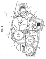
Fig. 2 is a schematic diagram illustrating the structure of the image forming unit (2) of the image forming apparatus (100) illustrated inFig. 1 ; -
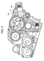
Fig. 3 is an illustrative example of the process cartridge (2) in which a light emitting device (20) is attached to the case to discharge the photoconductor (1) therein; -
Fig. 4 is a diagram for illustrating the method of measuring a friction factor of a photoconductor (1); -
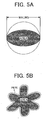
Fig. 5A and Fig. 5B are projected images of toner particles for explaining the factors of SF-1 and SF-2, respectively; -
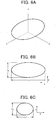
Fig. 6A is a schematic diagram illustrating the appearance of the toner particle; and -
Figs. 6B and 6C are schematic cross sections illustrating the factors, i.e., r1, r2, and r3, of the toner particle. - The present invention will be described below in detail with reference to several embodiments and accompanying drawings.
-
Fig. 1 is a schematic diagram illustrating the structure of an image forming apparatus (100) according to an embodiment of the present invention. Here will be described one embodiment which is applied to the image forming apparatus (100) using electrophotography. The image forming apparatus (100) is referred to as "tandem image forming apparatus" and forms color images by using four color toners. The four color toners are yellow, cyan, magenta and black (hereinafter referred to as Y, C, M and K, respectively). This image forming apparatus (100) has four photoconductors (1Y), (1C), (1M) and (1K) as the latent image bearing members (1). In this embodiment, the photoconductor (1) having a drum form is used but a photoconductor (1) having a belt form can be adopted. Each photoconductor (1Y), (1C), (1M) and (1K) rotates in the direction indicated by the arrow illustrated inFig. 1 while each photoconductor (1) contacts an intermediary transfer belt (6A) serving as surface movable member. - In the following, an illustrative example, which does not form part of the present invention, is described with reference to
Figs. 2 and3 . -
Fig. 2 is a schematic diagram illustrating a composition of an image forming unit (2) which contains the photoconductor (1). The characters indicating color, which are Y, C, M and K, are omitted because each composition around each photoconductor (1Y), (1C), (1M) and (1K) contained in each image forming unit (2Y), (2C), (2M) and (2K) , respectively, is just the same. Thus, only one image forming unit (2) is representatively illustrated in this figure. Around the photoconductor (1), a developing device (5) which includes a stirring convey screw (5B) and a doctor blade (5C) and which is configured to convert a latent image into a toner image, a pre-cleaning discharger (hereinafter referred to as PCL, which represents PreCleaningLamp) 20 configured to discharge the charged electric potential of the photoconductor (1), a lubricant applicator (21) configured to apply a lubricant to the photoconductor (1), a cleaner (7) for removing toner particles remaining on the photoconductor (1), and a charger (3) configured to charge the photoconductor (1) are placed according to the moving direction of the surface of the photoconductor (1). This image forming unit (2) preferably can serve as process cartridge (2). - Further, the composition of the image forming apparatus (100) of the present invention will be described below with reference to
Figs. 1 and2 . - The charger (3) charges the surface of the photoconductor (1) with a negative polarity. The charger (3) in this embodiment contains a charging roller (3A) as a charging member, which performs charging while the charging roller (3A) is in contact with or placed closely to the photoconductor (1). That is, the charger roller (3A) included in the charger (3) is in contact with or placed closely to the photoconductor (1) and the charger (3) applies a negative bias to the charging roller (3A) to charge the surface of the photoconductor (1). The direct current charging bias is applied to the charging roller (3A) such that the surface potential of the photoconductor (1) ranges from -400 to -500 V. As charging bias, it is possible to apply a direct current voltage overlapped with an alternating current voltage. In addition, the charger (3) can contain a cleaning roller (3B) configured to clean the surface of the charging roller (3A). Thereby, bad charging such as uneven charging ascribing to the charging roller (3A) can be avoided even when a small amount of toner is attached to the charging roller (3A). Furthermore, it is allowed to roll a thin film around both ends of the peripheral surface of the charging roller (3A) in the axial direction and contact the thin-film-rolled charging roller (3A) with the surface of the photoconductor (1). In this case, the surface of the charging roller (3A) can be set very close to the surface of the photoconductor (1) such that the distance therebetween is just the thickness of the thin film. Thereby, the chance of the charging roller (3A) contacting with the toner remaining on the photoconductor (1) becomes small.
- After the surface of the photoconductor (1) is charged, respective latent images corresponding to respective colors are formed on the surface of the photoconductor (1) when an irradiating device (4) irradiates the surface of the photoconductor (1). The irradiating device (4) in this embodiment is an irradiator using a light beam, but other irradiators such as an irradiator composed of LED arrays and an image focusing device can be also used.
- The developing device (5) contains a developing roller (5A) serving as a developer bearing member which is partially exposed from the opening of the casing of the developing device (5). The toner for use in this embodiment is a double component developer containing a toner and a carrier. However, a single component developer including no carrier can be also used. The developing device (5) contains toners therein, which are replenished from respective color toner bottles. The developing roller (5A) contains a magnet roller serving as a means to generate a magnetic field and a developing sleeve which coaxially rotates around the magnet roller. The magnetic force generated by the magnet roller forms filaments of carriers contained in the developer on the developing roller (5A). The carrier filaments are transferred to an area (hereinafter referred to as developing area) where the developing roller (5A) faces the photoconductor (1). The surface of the developing roller (5A) and the surface of the photoconductor (1) move in the same direction at the developing area while the linear velocity of the former is fast relative to that of the latter. At this point, a bias of -300 V is applied to the surface of the developing roller (5A) by a power supply (not shown) and thereby the developing electric field is formed at the developing area. Thus, when the carrier filaments on the developing roller (5A) abrade the surface of the photoconductor (1) , the toner particles attached to the surface of the carrier is attracted to the surface of the photoconductor (1) to perform development.
- The intermediary transfer belt (6A) having no end, which is included in a transfer device (6), is stretched onto three supporting rollers (6B), (6C) and (6D) and moves in the direction indicated by the arrow illustrated in the figure. On the intermediary belt (6A), the toner images on each photoconductor (1Y), (1C), (1M) and (1K) are transferred on each other by an electrostatic transfer method. A transfer charger can be used in the electrostatic transfer method but a transfer roller (6E), which can restrain the amount of dust generated at the time of transfer, is adopted in this embodiment. Specifically, on the back of each portion of the intermediary transfer belt (6A) which contacts each photoconductor (1Y), (1C), (1M) and (1K), first transfer rollers (6EY), (6EC), (6EM) and (6EK) are placed as transfer device (6). A first transfer area is formed between a portion of the intermediary transfer belt (6A) pressed by the first transfer roller (6E) and the photoconductor (1). When each toner image on each photoconductor (1Y), (1C), (1M) and (1K) is transferred to the intermediary transfer belt (6A), a positive bias is applied to the first transfer roller (6E). Thereby, a transfer electric field is formed in the area (hereinafter referred to as transfer area) where each first transfer is performed. Therefore, the toner images on each photoconductor (1Y), (1C), (1M) and (1K) are electrostatically attached and thus transferred to the intermediary transfer belt (6A).
- Around the intermediary belt (6A) is provided a belt cleaning device (6F) configured to remove toners remaining on the surface of the intermediary transfer belt (6A). The belt cleaning device (6F) collects unwanted toners attached to the surface of the intermediary transfer belt (6A) with a fur brush and a cleaning blade. The unwanted toner collected is transferred from within a belt cleaning device (6F) to a waste toner bottle (not shown) by a transfer means (not shown). The intermediary transfer belt (6A) is an endless single layer belt having a volume resistance of from 109 to 1011 Ωm and is preferably made of poly vinylidene fluoride (PVDF). Also multiple resin layers including an elastic layer can be used.
- In addition, a second transfer roller (6G) is provided so as to be brought into contact with the portion of the intermediary transfer belt (6A) which is stretched on the supporting roller (6D). A second transfer area is formed between this intermediary belt (6A) and the second transfer roller (6G). A transfer paper serving as a recording material is fed to this second transfer area according to the predetermined timing. This transfer paper is set in a paper feeder cassette (9) located below the irradiating device (4) as illustrated in
Fig. 1 and transferred to the second transfer area by a pickup roller (10), a pair of register rollers (11), etc. - The overlaid toner image on the intermediary transfer belt (6A) is transferred to the transfer paper altogether at the second transfer area. At the time of this second transfer, a positive bias is applied to the second transfer roller (6G) to form a transfer electric field and thereby the toner image on the intermediary transfer belt (6A) is transferred to the transfer paper.
- The lubricant applicator (21) configured to apply a lubricant mainly contains a molded lubricant (21B) set in a fixed case, a brush roller (21A) located so as to contact the molded lubricant (21B) for scraping and applying the lubricant, and a pressure spring (21C) which compresses the molded lubricant (21B) to the brush roller (21A). The molded lubricant (21B) has a rectangular solid form and preferably a stick form. In addition the brush roller (21B) has a form extending in the axial direction of the photoconductor (1). Although the molded lubricant (21B) is an expendable item and thus the thickness thereof naturally becomes thin with time, the pressure spring (21C) applies a force to the molded lubricant (21B) against the brush roller (21C) and therefore the molded lubricant (21B) is constantly pressed to contact the brush roller (21A). Thus, almost all of the molded lubricant (21B) can be used up.
- The lubricant applicator (21) can be provided in the cleaner (7) together with the cleaning blade (7A). In this case, toners remaining on the photoconductor (1) attach to the brush when the brush abrades the photoconductor (1). Then the toners attached to the brush are shaken off by a flicker (not shown) and transferred to a collection and transfer means (not shown) or drop off for collection when the toners attached to the brush contact the molded lubricant (21B).
- Specific preferred examples of such lubricants include aliphatic fatty acid metal salts, silicone oils and fluorine-containing resins. These can be used alone or in combination. Especially fatty acid metal salts are more preferred. Specific preferred examples of the fatty acids forming the fatty acid metal salts include straight chain hydrocarbons, such as myristic acid, palmitic acid, stearic acid and oleic acid. Among them, stearic acid is more preferred. Specific preferred examples of the metals include lithium, magnesium, calcium, strontium, zinc, cadmium, aluminum, cerium, titan, and iron. Specific preferred examples of the fatty acid metal salts include zinc stearate, magnesium stearate, aluminum stearate and iron stearate. Especially zinc stearate is more preferred.
- The cleaner (7) contains the cleaning blade (7A), a supporting member (7B), a toner collecting coil (7C) and a blade pressure spring (7D). The cleaning blade (7A) removes toners remaining on the photoconductor (1) after transfer. The cleaning blade (7A) is provided to the cleaner (7) by attaching the cleaning blade (7A) to the supporting member (7B). The supporting member (7B) has no specific limitation and can be made of metals, plastics, ceramics, etc.
- The cleaning blade (7A) uses an elastic substance having a low friction factor, for example, urethane resins, silicone resins and fluorine containing resins. Especially urethane elastomers, silicone elastomers and fluorine elastomers are preferred. For a cleaning blade (7A), hot curing urethane resins are preferred. Especially urethane elastomers are more preferred in terms of anti-abrasion, anti-ozone and anti-contamination. The elastomers mentioned above include rubber. The cleaning blade (7A) preferably has a degree of hardness of from 65 to 85 by JIS-A. The cleaning blade (7A) preferably has a thickness of from 0.8 to 3.0 mm and a protrusion in the amount of from 3 to 15 mm. Further conditions such as contact pressure, contact angle, the amount of inroad can be optionally determined.
- The image forming apparatus (100) of the present invention uses a toner having an average circularity not less than 0.94.
- To obtain this average circularity, toners made of dry pulverization are subject to thermal or mechanical sphere treatment.
- The thermal sphere treatment is performed by, for example, spraying toner particles to an atomizer, etc. with a heated airflow. The mechanical sphere treatment is performed by stirring toners with a mixture solvent including ingredients such as a glass having a small specific gravity in a mixing device, for example, a ball mill. However, in the thermal sphere treatment, the toner particles tend to aggregate and thus the toner particles obtained have a large particle diameter. In contrast, in the mechanical sphere treatment, fine powder toners tend to be generated. Therefore, an additional classification process is required.
- In the case of toners prepared in an aqueous solvent, the form of the toner can be controlled by vigorously stirring in the process of removing the solvent.
- The circularity is defined by the following relationship: Circularity SR = (the circumferential length of the circle having the area equal to a projected toner area /the circumferential length of the projected toner area) x 100%. The SR value is close to 100% as a toner particle gets closer to a true sphere. When toners having a high circularity are on carriers or a developing roller (5A), such toners tend to be affected by lines of electric force and thus the toner is transferred exactly along the lines of electric force of a latent electrostatic image. When fine latent dots are reproduced, fine line reproducibility becomes excellent since the toners can be densely and uniformly arranged. Further, toners having a high circularity value have a smooth surface and a good fluidity and thus tend to be affected by lines of electrical force. Therefore, the toners are easily transferred exactly along the lines of electric force. As a result, the transfer rate tends to be high and a quality image can be obtained. Furthermore, when the intermediary transfer belt (6A) is pressed to the photoconductor (1), toners having a high circularity value evenly contact the intermediary transfer belt (6A) and the contact area of the toners is uniform, resulting in improvement of the transfer rate. In contrast, when toners have an average circularity less than 0.94, it is impossible to perform exact development and a high rate transfer. This is because the surface of toners having an irregular form are not charged uniformly and are hard to move exactly along an electric field since the center of the gravity is deviated from that of the charge.
- However, toners having a high circularity value easily sneak into a gap between the cleaning blade (7A) and the photoconductor (1), resulting in poor cleaning performance. Therefore, as a means to reduce the attachment force between toners and the photoconductor (1), a PCL (20) serving as an irradiator is provided for the image forming apparatus (100) of the present invention. As illustrated in
Fig. 2 , the PCL (20) is provided on the downstream side from the transfer area and on the upstream side from the cleaner (7). The PCL (20) can decay the amount of charge of the photoconductor (1) before cleaning and therefore removing the toners remaining on the photoconductor (1) becomes easy. Specific examples of the PCL (20) include laser diodes (LDs), light emitting diodes (LEDs), electroluminescences (ELs), and fluorescent lamps, each of which can reduce the amount of charge on the photoconductor (1) by irradiating the photoconductor (1) with light. The PCL (20) is preferably an EL or LD and more preferably an EL because it has a simple structure. ELs are light weight and thin relative to fluorescent lamps. In addition, ELs can irradiate a wide area compared with LEDs which contain small elements arranged in array. When the PCL (20) is set within the transfer device (6) and further the intermediary transfer belt (6A) is made of a resin having a high transparency, the PCL (20) can irradiate the photoconductor (1) through the intermediary transfer belt (6A). - Next an illustrative example will be described with reference to
Fig. 3 . - The example basically has the same structure as that of the embodiment. Outside the case where the photoconductor (1) and the cleaner (7) are provided, a base plate (20A) to which the PCL (20) can be provided and a light shield member (20B) to sandwich the
PCL 20 are provided. In the second embodiment, a black mylar is adopted as light shield member (20B). The light shield member (20B) can prevent the light irradiated from the PCL (20) from reaching the transfer belt and thus the images obtained are not defective. In addition, by providing the light shield member (20B) on the base plate (20A) for the PCL (20), the base plate (20A) is not directly exposed when the process cartridge (2) is pulled out, which is user-friendly. Further, by providing the base plate (20A) on the case and the light shield member (20B) on the base plate (20A), the PCL (20) can be easily maintained and also the process cartridge (2) does not have to be jumboized. - Image forming operation of the image forming apparatus (100) of the present invention will be described next with reference to one image forming unit (2). When the image forming operation starts, the charger (3) uniformly charges the surface of the photoconductor (1) with a negative bias. Next, the irradiating device (4) scans the surface of the photoconductor (1) with a laser beam according to image data to form a latent image thereon. The developing device (5) converts this latent image into a toner image. The toner used is preferably a two-component developer including a carrier, which is suitable for a color toner.
- When the photoconductor (1) on which the toner image is formed rotates to the transfer area, the toner image contacts a portion of the intermediary belt (6A) which moves into the transfer area at the same timing. At the transfer area, the toner developed on the photoconductor (1) is transferred to the intermediary transfer belt (6A) by function of the electric field and upon an application of nipping pressure. The toner image is formed on the intermediary transfer belt (6A) through this transfer. When the "tandem image forming apparatus" is used, there are a plurality of the photoconductor (1)s therein, the number of which is equivalent to that of the number of color toners used. Therefore, this transfer operation is repeated multiple times to form a color toner image on the intermediary transfer belt (6A).
- The toner image on the intermediary transfer belt (6A) is transferred to a recording member at the second transfer area by function of the electric field and upon application of nipping pressure. The recording member is fed from the paper feeder cassette (9) and guided to the pair of register rollers (11) by a transfer roller using a transfer guide (not shown) to the second transfer area according to the predetermined timing. The full color toner image is formed on the recording member through this transfer. The recording member on which the full color toner image is formed is fixed at a fixing device (8) which contains a heat roller (8A) and a pressure roller (8B) and then discharged to an output tray of the image forming apparatus (100) via a paper discharging roller (12).
- The surface potential of the photoconductor (1) before the transfer is performed is -500 V at the ground (white background portion) and -50 V at the image portion which has been irradiated by a laser beam. A developing bias having a direct currency of -500 V and an alternating currency of from 0.5 to 2 kV is applied to toners having a negative polarity and thus the toners are attached to the image portion. At the transfer area, the toner image is transferred to the intermediary transfer belt (6A) by a transfer bias having a direct currency of 400 to 450 V and an alternating currency of from 0.5 to 2 kV. After the transfer, the surface potential of the photoconductor (1) is about -200V at the ground portion (white background portion) and about -10 V at the image portion. The toners remaining on the photoconductor (1) after the transfer is strongly attracted to the edge portion of the image on the surface of the photoconductor (1) by the force of the electric field formed by the -200 V and -10 V. These toner particles sneak through the cleaning blade (7A) and are charged in the next image forming process, resulting in a defective image having, for example, background development and white spots. To prevent this poor cleaning performance, the PCL (20) irradiates the photoconductor (1) with light to change the potential of the ground portion having no toner thereon from -200 to 0 V to form an electric field between this 0 V and the - 10 V which is applied to the image portion, thereby reducing the attraction force between the toner and the photoconductor (1).
- After this, the brush roller (21A) included in the lubricant applicator (21) abrasively scrapes the lubricant, i.e., zinc stearate, from the molded lubricant (21B) and the scraped toner is attached to the brush roller (21A). Next the brush roller (21A) abrades the surface of the photoconductor (1) to apply the lubricant thereto. Then the lubricant is pressed to the photoconductor (1) to form a thin film thereon by the cleaning blade (7A) which contacts the photoconductor (1). The toner particles on the photoconductor (1) where this thin film is formed are easy to remove. Further, considering that the electric field formed between the toners and the surface of the photoconductor (1) has been weakened and therefore the attraction force therebetween has also been weakened, it is possible to clear the photoconductor (1) of even the toner particles having a high average circularity not less than 0.94.
- Furthermore, the lubricant thin film formed on the photoconductor (1) reduces the friction factor of the photoconductor (1). The friction factor µ of the photoconductor (1) is preferably not greater than 0.4 at this time. This friction factor µ can be controlled by the setting conditions of the lubricant applicator (21) such as the pressure from the pressure spring (21C) against the molded lubricant (21B), the brush density of the brush roller (21A), the diameter of the brush, the number of rotation of the roller and the rotation direction.
- By limiting the friction factor µ of the photoconductor (1) not greater than 0.4, the friction between the photoconductor (1) and the cleaning blade (7A) can be restrained. Therefore, the cleaning blade (7A) can avoid transformation and curling up and prevent the toner particles remaining on the photoconductor (1) from sneaking therethrough, resulting in prevention of poor cleaning performances. The friction factor µ of the photoconductor is more preferably not greater than 0.3.
- The friction factor µ of the photoconductor (1) is measured by Oiler belt method as described below.
Fig. 4 is a diagram illustrating the measuring method of the friction factor µ of the photoconductor (1). The measuring method is as follows: Stretch a quality paper of a medium thickness serving as a belt in the longitudinal direction over a fourth of the circumference of the photoconductor drum (1); Attach a force gauge to one side of the belt and a weight of, for example, 100 gr, i.e., a force of 0.98 N, to the other side thereof to pull the force gauge; Increase the weight until the belt moves; Read the value of the gauge when the belt moves; Assign the value into the following relationships: µs = 2 /π x ln (F/0.98), where µs represents static friction factor, F represents the measured value; and calculate the friction factor of the photoconductor (1). In this embodiment, the friction factor µ of the photoconductor (1) of the image forming apparatus (100) represents the value obtained after it becomes constant. This is because the friction factor µ of the photoconductor (1) of the image forming apparatus (100) initially varies due to the other devices provided in the image forming apparatus (100). The friction factor µ becomes constant after about 1,000 sheets of A4 paper are used for image formation. - Toners having a relatively small volume average particle diameter Dv are excellent in improving fine line reproducibility. Therefore, it is preferred to use a toner having a volume average particle diameter not greater than 8 µm. However, when the volume average particle diameter of the toner is too small, developability and cleanability deteriorate. In addition, toner particles having a too small particle diameter tend to be hard to be developed and therefore the number of such toner particles increases on the surface of carriers and the developing roller (5A). Consequently, such toner particles cannot sufficiently contact other carriers or the developing roller (5A) and thus the number of the reversely charged toner particles increases, resulting in defective images having, for example, background development. Thus, the volume average particle diameter is preferably not less than 3 µm.
- The particle diameter distribution represented by a ratio (Dv/Dn) of the volume average particle diameter (Dv) to the number average particle diameter (Dn) is preferably from 1.05 to 1.40.
- By using a toner having a sharp particle diameter distribution, the toner charge distribution can be uniformed. When the ratio (Dv/Dn) is too large, the toner charge distribution is wide and the number of reversely charged toner particles T1 increases and therefore, quality images are difficult to obtain. When the ratio (Dv/Dn) is too small, manufacturing such toner particles is difficult and therefore not practical. The particle diameter of a toner is measured using COULTER COUNTER MULTI-SIZER (manufactured by Beckman Coulter, Inc.) with an aperture of 50 µm which is selected according to the particle diameter of the toners to be measured. The average particle diameter is calculated based on measurement of 50,000 toner particles.
- The toner for use in the image forming apparatus (100) preferably has a form having a form factor SF-1 of from 100 to 180, and a form factor SF-2 of from 100 to 180 with regard to circularity.
Figs. 5 are schematic diagrams for explaining the factors of SF-1 and SF-2.Fig. 5A and Fig. 5B are diagrams for explaining the form factor SF-1 and SF-2, respectively. As illustrated inFig. 5A , the form factor SF-1 represents the degree of roundness of a toner particle and is defined by the following equation (1):
- When the SF-1 is 100, the toner particle is a true sphere. It can be said that as SF-1 increases, the toner form differs away from a true sphere form.
- As illustrated in
Fig. 5B , the form factor SF-2 represents the degree of concavity and convexity of a toner particle and is defined by the following equation (2):
- When the SF-2 is 100, the surface of the toner particle does not have any concavity or convexity. It can be said that as SF-2 increases, the toner surface becomes rough.
- The form factors SF-1 and SF-2 are determined by the following method:
- (1) a photograph of particles of a toner is taken using a scanning electron microscope (S-800, manufactured by Hitachi Ltd.); and
- (2) particle images of 100 toner particles are analyzed using an image analyzer (LUSEX 3 manufactured by Nireco Corp.).
- When the toner has a form close to a true sphere, the contact between toner particles becomes point to point contact. Thereby the adhesion force between toner particles weakens and therefore, the toner has a good fluidity. In addition, the adhesion force between the toner and the photoconductor (1) is also weak and the transfer rate of the toner is high. Therefore, the toners remaining on the photoconductor (1) are easy to remove.
- It is preferred that the form factors SF-1 and SF-2 be not less than 100. When the form factors SF-1 and SF-2 are large, the toner form is irregular and the toner charge distribution is wide. Therefore, the image developed from a latent image is not true thereto. Further, transferring an image is not performed truly to a transfer electric field, resulting in deterioration of the quality of images. Furthermore, the transfer rate declines and the amount of the amount of remaining toner increases. To avoid this, a large cleaner (7) is required and which is disadvantageous in terms of designing the image forming apparatus (100). Therefore, it is preferred that SF-1 and SF-2 both be not greater than 180.
- In addition, the toner for use in the image forming apparatus (100) can have a substantially sphere form.
Figs. 6 are schematic diagrams illustrating the appearance and form of the toner.Fig. 6A is a diagram illustrating the appearance of the toner andFig. 6B illustrates a cross section of the toner particle. InFig. 6A , a major axis r1, which is the longest axis of the toner particle, is along x-axis, a minor axis r2, which is the second longest axis thereof, is along y-axis, and a thickness r3, which is the shortest axis thereof, is along z-axis. The relationships between r1, r2 and r3 are: r3 ≤ r2 ≤ r1. This toner particle is substantially a true sphere satisfying the following relationships: 0.5 ≤ r2/r1 ≤ 1.0; and 0.7 ≤ r3/r2 ≤ 1.0. When the ratio (r3/r2) is 1.0, the toner particle is a substantially true sphere and thus the toner charge distribution is narrow. However, when the ratio (r2/r1) is too small, the particle form of the toner is apart' from the true sphere and thus the toner charge distribution is wide. Also, when the ratio (r3/r2) is too small, the particle form of the toner is also apart from the true sphere form and thus the toner charge distribution is wide. - The particle diameters, i.e., r1, r2 and r3, of a toner particle are determined by observing 100 toner particles with a scanning electron microscope while the viewing angle is changed.
- The form of the toner is dependent on manufacturing methods. For example, the toner made by using dry pulverization methods has a rough surface and an irregular form. However, the toner made by this dry pulverization method can be made to be close to the true sphere when the toner is subject to mechanical or heat treatment. The toner made by forming a droplet using suspension polymerization methods or emulsion polymerization methods usually has a smooth surface and is close to the true sphere form. In addition, the toner can have an oval form when the toner constituent is stirred and sheared in the middle of the reaction proceeding in the solvent containing the toner constituent.
- The toner particle having such a substantially true sphere form is preferably prepared by the following method: Toner constituents including at least a polyester prepolymer having a functional group having a nitrogen atom, another polyester resin, a colorant and a release agent are dissolved or dispersed in an aqueous solvent in the presence of a particulate resin to crosslink and/or elongate the polyester prepolymer for preparing toner particles.
- The toner constituents and toner manufacturing method will be described in detail below.
- Polyesters are obtained when polyols (PO) and polycarboxylic compounds are subject to polycondensation reaction.
- Suitable preferred polyols (PO) include diols (DIO) and polyols (TO) having three or more hydroxyl groups. It is preferable to use diols (DIO) alone or mixtures in which a small amount of a polyol (TO) is added to a diol (DIO).
- Specific examples of the diols (DIO) include alkylene glycol (e.g., ethylene glycol, 1,2-propylene glycol, 1,3-propylene glycol, 1,4-butanediol and 1,6-hexanediol); alkylene ether glycols (e.g., diethylene glycol, triethylene glycol, dipropylene glycol, polyethylene glycol, polypropylene glycol and polytetramethylene ether glycol); alicyclic diols (e.g., 1,4-cyclohexane dimethanol and hydrogenated bisphenol A); bisphenols (e.g., bisphenol A, bisphenol F and bisphenol S); adducts of the alicyclic diols mentioned above with an alkylene oxide (e.g., ethylene oxide, propylene oxide and butylene oxide); adducts of the bisphenols mentioned above with an alkylene oxide (e.g., ethylene oxide, propylene oxide and butylene oxide); etc.
- Among these compounds, alkylene glycols having from 2 to 12 carbon atoms and adducts of bisphenols with an alkylene oxide are preferable. More preferably, adducts of bisphenols with an alkylene oxide, or mixtures of an adduct of bisphenols with an alkylene oxide and an alkylene glycol having from 2 to 12 carbon atoms are used.
- Specific examples of the polyols (TO) include aliphatic alcohols having three or more hydroxyl groups (e.g., glycerin, trimethylol ethane, trimethylol propane, pentaerythritol and sorbitol); polyphenols having three or more hydroxyl groups (trisphenol PA, phenol novolak and cresol novolak) ; adducts of the polyphenols mentioned above with an alkylene oxide; etc.
- Suitable polycarboxylic acids (PC) include dicarboxylic acids (DIC) and polycarboxylic acids (TC) having three or more carboxyl groups. It is preferable to use dicarboxylic acids (DIC) alone or mixtures in which a small amount of a polycarboxylic acid (TC) is added to a dicarboxylic acid (DIC).
- Specific examples of the dicarboxylic acids (DIC) include alkylene dicarboxylic acids (e.g., succinic acid, adipic acid and sebacic acid); alkenylene dicarboxylic acids (e.g., maleic acid and fumaric acid); aromatic dicarboxylic acids (e.g., phthalic acid, isophthalic acid, terephthalic acid and naphthalene dicarboxylic acids; etc. Among these compounds, alkenylene dicarboxylic acids having from 4 to 20 carbon atoms and aromatic dicarboxylic acids having from 8 to 20 carbon atoms are preferably used.
- Specific examples of the polycarboxylic acids (TC) having three or more hydroxyl groups include aromatic polycarboxylic acids having from 9 to 20 carbon atoms (e.g., trimellitic acid and pyromellitic acid).
- As the polycarboxylic acid (PC), anhydrides or lower alkyl esters (e.g., methyl esters, ethyl esters or isopropyl esters) of the polycarboxylic acids mentioned above can be used for the reaction with a polyol (PO).
- Suitable mixing ratio (i.e., an equivalence ratio [OH] /[ COOH]) of a polyol (PO) to a polycarboxylic acid (PC) ranges from 2/1 to 1/1, preferably from 1.5/1 to 1/1 and more preferably from 1.3/1 to 1.02/1.
- Polyols (PO) and polycarboxylic acid (PC) are subjected to polycondensation reaction as follows:
- (1) Heat a polyol and a polycarbonic acid to 150 to 280 °C in the presence of a known esterification catalyst such as tetra butoxy titanate and dibutyl tin oxide.
- (2) Remove the generated water while decreasing the pressure if necessary to obtain a polyester having a hydroxyl group. The polyester obtained preferably has a hydroxyl value of at least 5 and normally has an acid value of from 1 to 30 and preferably from 5 to 20. When a polyester has an acid value, the polyester can be easily charged with a negative polarity. In addition, a toner including such a polyester has a good affinity with a recording paper and therefore the low temperature fixability of the toner improves when fixing the toner onto the recording paper. However, when the acid value is too large, the charging stability of the toner tends to deteriorate especially to environmental changes.
- The weight average molecular weight is from 10, 000 to 400,000 and preferably from 20,000 to 200,000. It is not preferred to have too small weight average molecular weight because anti-offset properties deteriorate. It is not also preferred to have too large weight average molecular weight because low temperature fixability deteriorates.
- Other than the unmodified polyesters obtained from the polycondensation reaction mentioned above, suitable preferred examples of polyesters include urea-modified polyesters. Urea-modified polyesters are prepared by the following method:
- (1) React an end, for example, a carboxyl group and hydroxyl group, of the polyester obtained from the polycondensation reaction mentioned above with polyisocyanates (PIC) to obtain a polyester prepolymer (A) having an isocyanate group; and
- (2)Then react the polyester prepolymer (A) with amines to have cross-linked and/or elongated molecular chains.
- Specific examples of the polyisocyanates (PIC) include aliphatic polyisocyanates (e.g., tetramethylene diisocyanate, hexamethylene diisocyanate and 2,6-diisocyanate methylcaproate); alicyclic polyisocyanates (e.g., isophorone diisocyanate and cyclohexylmethane diisocyanate); aromatic diisoycantes (e.g., tolylene diisocyanate and diphenylmethane diisocyanate); aromatic aliphatic diisocyanates (e.g., α, α, α', α'-tetramethyl xylylene diisocyanate); isocyanurates; blocked polyisocyanates in which the polyisocyanates mentioned above are blocked with phenol derivatives, oximes or caprolactams; etc. These compounds can be used alone or in combination.
- Suitable mixing ratio (i.e., [NCO] /[OH]) of a polyisocyanate (PIC) to a polyester having a hydroxyl group varies from 5/1 to 1/1, preferably from 4/1 to 1.2/1 and more preferably from 2.5/1 to 1.5/1. When the [NCO]/[OH] ratio is too large, the low temperature fixability of the toner deteriorates. In contrast, when the ratio is too small, the content of the urea group in the modified polyesters decreases, thereby deteriorating the hot-offset resistance of the toner.
- The content of the constitutional component of a polyisocyanate (PIC) in the polyester prepolymer (A) having an isocyanate group at its end portion ranges from 0.5 to 40 % by weight, preferably from 1 to 30 % by weight and more preferably from 2 to 20 % by weight. When the content is too low, the hot offset resistance of the toner deteriorates and in addition the heat resistance and low temperature fixability of the toner also deteriorate. In contrast, when the content is too high, the low temperature fixability of the toner deteriorates.
- The number of the isocyanate groups included in a molecule of the polyester prepolymer (A) is at least 1, preferably from 1.5 to 3 on average, and more preferably from 1.8 to 2.5 on average. When the number of the isocyanate group is too small (less than 1 per 1 molecule), the molecular weight of the resultant urea-modified polyester decreases and thereby the hot offset resistance deteriorates.
- Specific examples of the amines (B), which are to be reacted with a polyester prepolymer (A), include diamines (B1), polyamines (B2) having three or more amino groups, amino alcohols (B3) amino mercaptans (B4) , amino acids (B5), and blocked amines (B6) in which the amines (B1-B5) mentioned above are blocked.
- Specific examples of the diamines (B1) include aromatic diamines (e.g., phenylene diamine, diethyltoluene diamine and 4,4'-diaminodiphenyl methane); alicyclic diamines (e.g., 4,4'-diamino-3,3'-dimethyldicyclohexyl methane, diaminocyclohexane and isophoron diamine); aliphatic diamines (e.g., ethylene diamine, tetramethylene diamine and hexamethylene diamine); etc.
- Specific examples of the polyamines (B2) having three or more amino groups include diethylene triamine, triethylene tetramine. Specific examples of the amino alcohols (B3) include ethanol amine and hydroxyethyl aniline. Specific examples of the amino mercaptan (B4) include aminoethyl mercaptan and aminopropyl mercaptan. Specific examples of the amino acids (B5) include amino propionic acid and amino caproic acid. Specific examples of the blocked amines (B6) include ketimine compounds which are prepared by reacting one of the amines B1-B5 mentioned above with a ketone such as acetone, methyl ethyl ketone and methyl isobutyl ketone; oxazoline compounds, etc. Among these compounds, diamines (B1) and mixtures in which a diamine (B1) is mixed with a small amount of a polyamine (B2) are preferable.
- The mixing ratio (i.e., a ratio [ NCO] /[NHx] ) of the content of the prepolymer (A) having an isocyanate group to the amine (B) ranges from 1/2 to 2/1, preferably from 1.5/1 to 1/1.5 and more preferably from 1.2/1 to 1/1.2. When the mixing ratio is too low or too high, the molecular weight of the resultant urea-modified polyester decreases, resulting in deterioration of the hot offset resistance of the resultant toner.
- The modified polyesters may include a urethane linkage as well as a urea linkage. The molar ratio (urea/urethane) of the urea linkage to the urethane linkage may vary from 100/0 to 10/90, preferably from 80/20 to 20/80 and more preferably from 60/40 to 30/70. When the content of the urea linkage is too low, the hot offset resistance of the resultant toner deteriorates.
- Urea-modified polyesters can be prepared in different ways, including, for example, one-shot methods:
- (1) Heat a polyol and a polycarbonic acid to 150 to 280 °C in the presence of a known esterification catalyst such as tetra butoxy titanate and dibutyl tin oxide.
- (2) Remove the generated water while decreasing the pressure if necessary to obtain a polyester having a hydroxyl group.
- (3) React the polyester with a polyisocyanate (PIC) at temperatures in the range of from 40 to 140 °C to obtain a polyester prepolymer (A) having an isocyanate group.
- (4) React the prepolymer (A) with an amine (B) at temperatures in the range of from 0 to 140°C to obtain a urea-modified polyester.
- A solvent or mixture of solvents can be optionally used for the reaction of the polyester with the (PIC) and the reaction of the polymer (A) with the amine (B).
- Usable solvents should be inactive to isocyanates (PIC) and suitable preferred solvents include, but are not limited to, aromatic solvents such as toluene and xylene; ketones such as acetone, methyl ethyl ketone and methyl isobutyl ketone; esters such as acetic ether; amides such as dimethyl formamide and dimethyl acetamide; and ethers such as tetrahydrofuran.
- In the crosslinking reaction and/or elongation reaction of a polyester prepolymer (A) with an amine (B), a reaction inhibitor can be used if desired to control the molecular weight of the resultant urea-modified polyester. Specific examples of such a reaction inhibitor include monoamines (e.g., diethyl amine, dibutyl amine, butyl amine and lauryl amine), and blocked amines (i.e., ketimine compounds) prepared by blocking the monoamines mentioned above.
- The weight average molecular weight of the urea-modified polyesters is not less than 10,000, preferably from 20,000 to 10,000,000 and more preferably from 30,000 to 1,000,000. When the weight average molecular weight is too low, the hot offset resistance of the resultant toner deteriorates. The number average molecular weight of the urea-modified polyesters is not particularly limited (i.e., the weight average molecular weight should be primarily controlled so as to be in the range mentioned above) when the unmodified polyester resin mentioned above is used in combination. Namely, controlling of the weight average molecular weight of the modified polyester resins has priority over controlling of the number average molecular weight thereof. However, when a urea-modified polyester is used alone, the number average molecular weight thereof is from 2, 000 to 15, 000, preferably from 2, 000 to 10, 000 and more preferably from 2, 000 to 8,000. When the number average molecular weight is too large, the low temperature fixability of the resultant toner deteriorates, and in addition the gloss of full color images decreases when the toner is used in a full color image forming apparatus.
- By using a combination of a urea-modified polyester with an unmodified polyester, the low temperature fixability of the toner improves and in addition the toner can produce color images having high gloss when the toner is used in the full-color image forming apparatus (100). Therefore, the combinational use of an unmodified polyester and a urea-modified polyester is preferable to a single use of the urea-modified polyester. As the unmodified polyester, polyester resins modified by a linkage (such as urethane linkage) other than a urea linkage, can also be used as well as unmodified polyester resins. When a mixture of a modified polyester with a urea-unmodified polyester is used, it is preferred that the modified polyester at least partially mix with the unmodified polyester in terms of the low temperature fixability and hot offset resistance of the resultant toner. Namely, it is preferred that the unmodified polyester have a structure similar to that of the urea-modified polyester. The mixing ratio of an unmodified polyester to a urea-modified polyester varies from 20/80 to 95/5, preferably from 70/30 to 95/5, more preferably from 75/25 to 95/5, and even more preferably from 80/20 to 93/7. When the added amount of urea-modified polyester is too small, the hot offset resistance of the resultant toner deteriorates and, in addition, it is hard to impart a good combination of high temperature preservability and low temperature fixability to the resultant toner.
- The binder resin including the unmodified polyester and the modified polyester has a glass transition temperature (Tg) of from 45 to 65 °C, and preferably from 45 to 60 °C. When the glass transition temperature is too low, the high temperature preservability of the toner deteriorates. In contrast, when the glass transition temperature is too high, the low temperature fixability of the toner deteriorates.
- Since a urea-modified polyester resin tends to exist on the surface of the mother toner particle obtained, the resultant toner tends to show good high temperature preservability comparative with conventional toners containing a polyester resin as a binder resin even if the binder resin has a relatively low glass transition temperature.
- The toner of the present invention includes a colorant.
- Suitable colorants for use in the toner of the present invention include known dyes and pigments. Specific examples of the colorants include carbon black, Nigrosine dyes, black iron oxide, Naphthol Yellow S, Hansa Yellow (10G, 5G and G) , Cadmium Yellow, yellow iron oxide, loess, chrome yellow, Titan Yellow, polyazo yellow, Oil Yellow, Hansa Yellow (GR, A, RN and R), Pigment Yellow L, Benzidine Yellow (G and GR), Permanent Yellow (NCG), Vulcan Fast Yellow (5G and R), Tartrazine Lake, Quinoline Yellow Lake, Anthrazane Yellow BGL, isoindolinone yellow, red iron oxide, red lead, orange lead, cadmium red, cadmium mercury red, antimony orange, Permanent Red 4R, Para Red, Fire Red, p-chloro-o-nitroaniline red, Lithol Fast Scarlet G, Brilliant Fast Scarlet, Brilliant Carmine BS, Permanent Red (F2R, F4R, FRL, FRLL and F4RH), Fast Scarlet VD, Vulcan Fast Rubine B, Brilliant Scarlet G, Lithol Rubine GX, Permanent Red F5R, Brilliant Carmine 6B, Pigment Scarlet 3B, Bordeaux 5B, Toluidine Maroon, Permanent Bordeaux F2K, Helio Bordeaux BL, Bordeaux 10B, BON Maroon Light, BON Maroon Medium, Eosin Lake, Rhodamine Lake B, Rhodamine Lake Y, Alizarine Lake, Thioindigo Red B, Thioindigo Maroon, Oil Red, Quinacridone Red, Pyrazolone Red, polyazo red, Chrome Vermilion, Benzidine Orange, perynone orange, Oil Orange, cobalt blue, cerulean blue, Alkali Blue Lake, Peacock Blue Lake, Victoria Blue Lake, metal-free Phthalocyanine Blue, Phthalocyanine Blue, Fast Sky Blue, Indanthrene Blue (RS and BC), Indigo, ultramarine, Prussian blue, Anthraquinone Blue, Fast Violet B, Methyl Violet Lake, cobalt violet, manganese violet, dioxane violet, Anthraquinone Violet, Chrome Green, zinc green, chromium oxide, viridian, emerald green, Pigment Green B, Naphthol Green B, Green Gold, Acid Green Lake, Malachite Green Lake, Phthalocyanine Green, Anthraquinone Green, titanium oxide, zinc oxide, lithopone and the like. These materials are used alone or in combination. The content of the colorant in the toner is preferably from 1 to 15 % by weight, and more preferably from 3 to 10 % by weight, based on total weight of the toner. Master batch pigments, which are prepared by combining a colorant with a resin, can be used as the colorant of the toner for use in the image forming apparatus of the present invention. Specific examples of the resin for use in the master batch pigments or for use in combination with master batch pigments include the modified and unmodified polyester resins mentioned above; styrene polymers and substituted styrene polymers such as polystyrene, poly-p-chlorostyrene and polyvinyltoluene; styrene copolymers such as styrene-p-chlorostyrene copolymers, styrene-propylene copolymers, styrene-vinyltoluene copolymers, styrene-vinylnaphthalene copolymers, styrene-methyl acrylate copolymers, styrene-ethyl acrylate copolymers, styrene-butyl acrylate copolymers, styrene-octyl acrylate copolymers, styrene-methyl methacrylate copolymers, styrene-ethyl methacrylate copolymers, styrene-butyl methacrylate copolymers, styrene-methyl α-chloromethacrylate copolymers, styrene-acrylonitrile copolymers, styrene-vinyl methyl ketone copolymers, styrene-butadiene copolymers, styrene-isoprene copolymers, styrene-acrylonitrile-indene copolymers, styrene-maleic acid copolymers and styrene-maleic acid ester copolymers; and other resins such as polymethyl methacrylate, polybutyl methacrylate, polyvinyl chloride, polyvinyl acetate, polyethylene, polypropylene, epoxy resins, epoxy polyol resins, polyurethane resins, polyamide resins, polyvinyl butyral resins, acrylic resins, rosin, modified rosins, terpene resins, aliphatic or alicyclic hydrocarbon resins, aromatic petroleum resins, chlorinated paraffin, paraffin waxes, etc. These resins can be used alone or in combination.
- The toner for use in the image forming apparatus of the present invention includes a charge controlling agent.
- Specific examples of the charge controlling agent include known charge controlling agents such as Nigrosine dyes, triphenylmethane dyes, metal complex dyes including chromium, chelate compounds of molybdic acid, Rhodamine dyes, alkoxyamines, quaternary ammonium salts (including fluorine-modified quaternary ammonium salts), alkylamides, phosphor and compounds including phosphor, tungsten and compounds including tungsten, fluorine-containing activators, metal salts of salicylic acid, salicylic acid derivatives, etc.
- Specific examples of the marketed products of the charge controlling agents include BONTRON® 03 (Nigrosine dyes), BONTRON® P-51 (quaternary ammonium salt), BONTRON® S-34 (metal-containing azo dye), E-82 (metal complex of oxynaphthoic acid), E-84 (metal complex of salicylic acid), and E-89 (phenolic condensation product), which are manufactured by Orient Chemical Industries Co., Ltd.; TP-302 and TP-415 (molybdenum complex of quaternary ammonium salt), which are manufactured by Hodogaya Chemical Co., Ltd. ; COPY CHARGE® PSY VP2038 (quaternary ammonium salt), COPY BLUE® (triphenyl methane derivative), COPY CHARGE® NEG VP2036 and NX VP434 (quaternary ammonium salt), which are manufactured by Hoechst AG; LRA-901, and LR-147 (boron complex), which are manufactured by Japan Carlit Co., Ltd.; copper phthalocyanine, perylene, quinacridone, azo pigments and polymers having a functional group such as a sulfonate group, a carboxyl group, a quaternary ammonium group, etc.
- The content of the charge controlling agent is determined depending on the species of the binder resin used, whether or not an additive is added and toner manufacturing method (such as dispersion method) used, and is not particularly limited. However, the content of the charge controlling agent is typically from 0.1 to 10 parts by weight, and preferably from 0.2 to 5 parts by weight, per 100 parts by weight of the binder resin included in the toner. When the content is too high, the toner has too large charge quantity, and thereby the electrostatic force of a developing roller attracting the toner increases, resulting in deterioration of the fluidity of the toner and decrease of the image density of toner images.
- The toner for use in the image forming apparatus of the present invention includes a release agent. Suitable release agents include waxes having a melting point of from 50 to 120°C. When such a wax is included in the toner, the wax is dispersed in the binder resin and serves as a release agent at a location between a fixing roller and the toner particles. Thereby hot offset resistance can be improved without applying an oil to the fixing roller used.
- In the present invention, the melting point of the release agents is measured by a differential scanning calorimeter (DSC). The maximum absorption peak is defined as the melting point.
- Specific examples of the release agent include natural waxes such as vegetable waxes, e.g., carnauba wax, cotton wax, Japan wax and rice wax; animal waxes, e.g., bees wax and lanolin; mineral waxes, e.g., ozokelite and ceresine; and petroleum waxes, e.g., paraffin waxes, microcrystalline waxes and petrolatum. In addition, synthesized waxes can also be used. Specific examples of the synthesized waxes include synthesized hydrocarbon waxes such as Fischer-Tropsch waxes and polyethylene waxes; and synthesized waxes such as ester waxes, ketone waxes and ether waxes. Further, fatty acid amides such as 1, 2-hydroxylstearic acid amide, stearic acid amide and phthalic anhydride imide; and low molecular weight crystalline polymers such as acrylic homopolymer and copolymers having a long alkyl group in their side chain, e.g., poly-n-stearyl methacrylate, poly-n-laurylmethacrylate and n-stearyl acrylate-ethyl methacrylate copolymers, can also be used.
- The charge controlling agent, and the release agent can be kneaded with a masterbatch and a binder resin. In addition, the charge controlling agent, and the release agent can be added to an organic solvent when the toner constituent liquid is prepared.
- Now, the method for manufacturing the toner for use in the present invention will be explained. However, the manufacturing method is not limited to the examples presented herein below.
-
- (1) First, toner constituents including a colorant, an unmodified polyester resin, a polyester prepolymer having an isocyanate group, and a release agent are dissolved or dispersed in an organic solvent to prepare a toner constituent liquid.
Suitable preferred organic solvents include volatile organic solvents having a boiling point less than 100 °C since such solvent can be easily removed from the resultant toner particle dispersion.
Specific examples of the organic solvents include toluene, xylene, benzene, carbon tetrachloride, methylene chloride, 1,2-dichloroethane, 1,1,2-trichloroethane, chloroform, monochlorobenzene, dichloroethylidene, methyl acetate, ethyl acetate, methyl ethyl ketone, methyl isobutyl ketone, etc. These can be used alone or in combination. In particular, aromatic solvents such as toluene and xylene, and halogenated hydrocarbons such as 1,2-dichloroethane, chloroform and carbon tetrachloride are preferably used.
The addition quantity of the organic solvent is from 0 to 300 parts by weight, preferably from 0 to 100 parts by weight and more preferably from 25 to 70 parts by weight, per 100 parts by weight of the polyester prepolymer used. - (2) Next, the toner constituent liquid is emulsified in an aqueous medium in the presence of a surfactant and a particulate resin.
Suitable aqueous media include water, and mixtures of water with alcohols (such as methanol, isopropanol and ethylene glycol), dimethylformamide, tetrahydrofuran, cellosolves (such as methyl cellosolve) and lower ketones (such as acetone and methyl ethyl ketone).
The mixing ratio (A/T) of the aqueous medium (A) to the toner constituent liquid (T) is from 50/100 to 2000/100 by weight, and preferably from 100/100 to 1000/100 by weight. When the content of the aqueous medium is too low, the toner constituent liquid cannot be well dispersed, and thereby toner particles having a desired particle diameter cannot be produced. In contrast, when the content of the aqueous medium is too high, the manufacturing cost of the toner increases.
When the toner constituent liquid is dispersed in an aqueous medium, a dispersant can be preferably used to prepare a stable dispersion.
Specific examples of the surfactants include anionic surfactants such as alkylbenzene sulfonic acid salts, α-olefin sulfonic acid salts, and phosphoric acid salts; cationic surfactants such as amine salts (e.g., alkyl amine salts, aminoalcohol fatty acid derivatives, polyamine fatty acid derivatives and imidazoline), and quaternary ammonium salts (e.g., alkyltrimethyl ammonium salts, dialkyldimethyl ammonium salts, alkyldimethyl benzyl ammonium salts, pyridinium salts, alkyl isoquinolinium salts and benzethonium chloride); nonionic surfactants such as fatty acid amide derivatives, polyhydric alcohol derivatives; and ampholytic surfactants such as alanine, dodecyldi(aminoethyl)glycin, di)octylaminoethyle)glycin, and N-alkyl-N,N-dimethylammonium betaine.
By using a surfactant having a fluoroalkyl group, a good dispersion can be prepared even when a small amount of the surfactant is used. Specific examples of the anionic surfactants having a fluoroalkyl group include fluoroalkyl carboxylic acids having from 2 to 10 carbon atoms and their metal salts, disodium perfluorooctanesulfonylglutamate, sodium 3-{omega-fluoroalkyl(C6-C11)oxy}-1-alkyl(C3-C4) sulfonate, sodium 3-{omega-fluoroalkanoyl(C6-C8)-N-ethylamino}-1-propan esulfonate, fluoroalkyl(C11-C20)carboxylic acids and their metal salts, perfluoroalkylcarboxylic acids and their metal salts, perfluoroalkyl(C4-C12)sulfonate and their metal salts, perfluorooctanesulfonic acid diethanol amides, N-propyl-N-(2-hydroxyethyl)perfluorooctanesulfone amide, perfluoroalkyl(C6-C10)sulfoneamidepropyltrimethylammo nium salts, salts of perfluoroalkyl(C6-C10)-N-ethylsulfonyl glycin, monoperfluoroalkyl(C6-C16)ethylphosphates, etc.
Specific examples of the marketed products of such surfactants having a fluoroalkyl group include SURFLON® S-111, S-112 and S-113, which are manufactured by Asahi Glass Co., Ltd.; FRORARD® FC-93, FC-95, FC-98 and FC-129, which are manufactured by Sumitomo 3M Ltd.; UNIDYNE® DS-101 and DS-102, which are manufactured by Daikin Industries, Ltd.; MEGAFACE® F-110, F-120, F-113, F-191, F-812 and F-833 which are manufactured by Dainippon Ink and Chemicals, Inc.; ECTOP® EF-102, 103, 104, 105, 112, 123A, 306A, 501, 201 and 204, which are manufactured by Tohchem Products Co., Ltd.; FUTARGENT® F-100 and F150 manufactured by Neos; etc.
Specific examples of the cationic surfactants having a fluoroalkyl group include primary, secondary and tertiary aliphatic amino acids, aliphatic quaternary ammonium salts (such as perfluoroalkyl(C6-C10)sulfoneamidepropyltrimethylammo nium salts), benzalkonium salts, benzetonium chloride, pyridinium salts, imidazolinium salts, etc., all of which have a fluoroalkyl group Specific examples of commercially available products of these elements include SURFLON® S-121 (from Asahi Glass Co., Ltd.); FRORARD® FC-135 (from Sumitomo 3M Ltd.); UNIDYNE® DS-202 (from Daikin Industries, Ltd. ) ; MEGAFACE® F-150 and F-824 (from Dainippon Ink and Chemicals, Inc.); ECTOP® EF-132 (from Tohchem Products Co., Ltd.); FUTARGENT® F-300 (from Neos); etc.
In addition, particulate polymers can be added to stabilize the resultant mother toner particles formed in an aqueous medium. Therefore it is preferred that a particulate polymer be added to the aqueous medium such that the surface of the mother toner particles are covered with the particulate polymer at a covering ratio of from 10 to 90 %.
Specific examples of the particulate polymers include particulate polymethyl methacylate having a particle diameter of from 1 to 3 µm, particulate polystyrene having a particle diameter of from 0.5 to 2 µm, particulate styrene-acrylonitrile copolymers having a particle diameter of 1 µm, etc. Specific examples of the marketed particulate polymers include PB-200H (from Kao Corp.), SGP (Soken Chemical & Engineering Co., Ltd.), TECHNOPOLYMER® SB (Sekisui Plastics Co., Ltd.), SPG-3G (Soken Chemical & Engineering Co., Ltd.), MICROPEARL® (Sekisui Fine Chemical Co., Ltd.), etc.
In addition, an inorganic dispersant can be added to the aqueous medium. Specific examples of the inorganic dispersants include tricalcium phosphate, calcium carbonate, titanium oxide, colloidal silica, hydroxyapatite, etc.
Further, it is possible to stably disperse toner constituents in an aqueous medium using a polymeric protection colloid in combination with the inorganic dispersants and/or particulate polymers mentioned above.
Specific examples of such protection colloids include polymers and copolymers prepared using monomers such as acids (e.g., acrylic acid, methacrylic acid, α - cyanoacrylic acid, α-cyanomethacrylic acid, itaconic acid, crotonic acid, fumaric acid, maleic acid and maleic anhydride), acrylic monomers having a hydroxyl group (e.g., β-hydroxyethyl acrylate, β-hydroxyethyl methacrylate, β-hydroxypropyl acrylate, β - hydroxypropyl methacrylate, γ-hydroxypropyl acrylate, γ-hydroxypropyl methacrylate, 3-chloro-2-hydroxypropyl acrylate, 3-chloro-2-hydroxypropyl methacrylate, diethyleneglycolmonoacrylic acid esters, diethyleneglycolmonomethacrylic acid esters, glycerinmonoacrylic acid esters, N-methylolacrylamide and N-methylolmethacrylamide), vinyl alcohol and its ethers (e.g., vinyl methyl ether, vinyl ethyl ether and vinyl propyl ether), esters of vinyl alcohol with a compound having a carboxyl group (i.e., vinyl acetate, vinyl propionate and vinyl butyrate); acrylic amides (e.g, acrylamide, methacrylamide and diacetoneacrylamide) and their methylol compounds, acid chlorides (e.g., acrylic acid chloride and methacrylic acid chloride), and monomers having a nitrogen atom or an alicyclic ring having a nitrogen atom (e.g., vinyl pyridine, vinyl pyrrolidone, vinyl imidazole and ethylene imine).
In addition, polymers such as polyoxyethylene compounds (e.g., polyoxyethylene, polyoxypropylene, polyoxyethylenealkyl amines, polyoxypropylenealkyl amines, polyoxyethylenealkyl amides, polyoxypropylenealkyl amides, polyoxyethylene nonylphenyl ethers, polyoxyethylene laurylphenyl ethers, polyoxyethylene stearylphenyl esters, and polyoxyethylene nonylphenyl esters), and cellulose compounds such as methyl cellulose, hydroxyethyl cellulose and hydroxypropyl cellulose, can also be used as the polymeric protective colloid.
The dispersion method is not particularly limited, and low speed shearing methods, high speed shearing methods, friction methods, high pressure jet methods, ultrasonic methods, etc. can be used. Among these methods, high speed shearing methods are preferable because particles having a particle diameter of from 2 µm to 20 µm can be easily prepared. At this point, the particle diameter (2 to 20 µm) means a particle diameter of particles including a liquid.
When a high speed shearing type dispersion machine is used, the rotation speed is not particularly limited, but the rotation speed is typically from 1,000 to 30,000 rpm, and preferably from 5,000 to 20,000 rpm. The dispersion time is not also particularly limited, but is typically from 0.1 to 5 minutes. The temperature in the dispersion process is typically from 0 to 150 °C (under pressure), and preferably from 40 to 98 °C. - (3) At the same time when a toner constituent is dispersed in an aqueous medium, an amine (B) is added to the aqueous medium to be reacted with the polyester prepolymer (A) having an isocyanate group.
This reaction accompanies crosslinking and/or elongation of the molecular chains of the polyester prepolymer (A). The reaction time is determined depending on the reactivity of the amine (B) with the polyester prepolymer used, but is typically from 10 minutes to 40 hours, and preferably from 2 to 24 hours. The reaction temperature is from 0 to 150 °C, and preferably from 40 to 98 °C. In addition, known catalysts such as dibutyltin laurate and dioctyltin laurate, can be used for the reaction, if desired. - (4) After the reaction, the organic solvent is removed from the resultant dispersion (emulsion, or reaction product), and then the solid components are washed and then dried. Thus, a mother toner is prepared.
In order to remove the organic solvent, all the system is gradually heated while agitated under laminar flow conditions. Then the system is strongly agitated in a certain temperature range, followed by solvent removal, to prepare a mother toner having a spindle form.
In this case, when compounds such as calcium phosphate which are soluble in an acid or alkali are used as a dispersion stabilizer, it is preferable to dissolve the compounds by adding an acid such as hydrochloric acid, followed by washing of the resultant particles with water to remove calcium phosphate therefrom. In addition, calcium phosphate can be removed using a zymolytic method. - (5) Subsequently, a charge controlling agent is fixedly adhered to the mother toner. In addition, an external additive such as combinations of a particulate silica and a particulate titanium oxide, is adhered to the mother toner particle to prepare the toner of the present invention.
- In the process of preparing a developer by adding an external additive and a lubricant, it is possible to add and mix both of them simultaneously or separately. To mix external additives, etc., powder mixers are used. In addition, it is preferred that the powder mixers be equipped with a jacket and the like to adjust the internal temperatures thereof. Specific preferred examples of mixing facilities include v-type mixers, rocking mixers, Loedige Mixers, Nauta mixers and Henschel mixers. It is preferred to prevent an external additive from being embedded and a lubricant from forming a thin film on the toner by varying the mixing conditions such as the number of the rotation, the speed of nutation, time and temperature.
- By using this manufacturing method, the resultant toner can have a relatively small particle diameter and a narrow particle diameter distribution. By controlling the strong agitation during the solvent removing process, the shape of the toner can be controlled so as to be of a desired form, i.e., a form between a rugby ball and a true sphere form. In addition, the surface characteristics of the toner can also be controlled to produce a surface having a desired roughness, i.e., a surface that is not too smooth or too rough.
- External additives can boost fluidity, developability and chargeability of toner particles. Suitable preferred external additives include particulate inorganic materials. Especially, hydrophobic silica and/or hydrophobic titanium oxide are preferred. These particulate inorganic materials preferably have a primary particle diameter between 5 nm and 2 µm, and more preferably between 5 nm and 500 nm. In addition, it is preferred that the specific surface area of such particulate inorganic materials measured by a BET method be from 20 to 500 m2/g. The content of this external additive is preferably from 0.01 to 5 % by weight, and more preferably from 0.01 to 2.0 % by weight, based on the total weight of the toner composition.
- Specific examples of such inorganic particulate materials include alumina, barium titanate, magnesium titanate, calcium titanate, strontium titanate, zinc oxide, tin oxide, quartz sand, clay, mica, sand-lime, diatom earth, chromium oxide, cerium oxide, red iron oxide, antimony trioxide, magnesium oxide, zirconium oxide, barium sulfate, barium carbonate, calcium carbonate, silicon carbide, silicon nitride, etc. Other than the above, particulate polymers, (which can be prepared by a method such as soap free emulsion polymerization, suspension polymerization or dispersion polymerization), such as copolymers of polystyrene, methacrylic acid esters and acrylic acid esters, particulate polycondensation compounds (e.g., silicone resins, benzoguanamine resins and nylons), and polymers of thermosetting resins can also be used.
- When such external additives (fluidizers) are surface treated to improve hydrophobicity, good fluidity and chargeability can be maintained even in a high humidity environment. Suitable surfactants for use in the hydrophobizing treatment include silane coupling agents, silylation agents, silane coupling agents having a fluorinated alkyl group, organic titanate coupling agents, aluminum coupling agents, silicone oils, modified silicone oils, etc.
- The toner of the present invention can be mixed with a magnetic carrier and used as a two component developer. The ratio of the carrier to the toner is preferably 100/1 to 100/10 by weight. Also, the toner of the present invention can be used as a single component magnetic or non-magnetic toner without using a carrier.
- The illustrative example of an image forming apparatus (100) contains a detachable process cartridge which integrally supports the photoconductor (1) and at least one device selected from the group consisting of the lubricant applicator (21), the charger (2), the developing device (5) and the cleaner (7). To the image forming apparatus (100) the PCL (20) is provided as irradiator and therefore the image forming apparatus (100) can clear the photoconductor (1) of even a toner having a circularity not less than 0.94.
- In addition, the image forming apparatus can use a detachable process cartridge which integrally supports the photoconductor (1) and at least one device selected from the group consisting of the lubricant applicator (21), the charger (2), the developing device (5) and the cleaner (7) and further includes the PCL (20) located on the upstream side from the cleaner (7) relative to the rotation direction of the photoconductor (1) as irradiating device to discharge the photoconductor (1). The PCL (20) provided to the process cartridge can attenuate the remaining potential of the photoconductor (1), especially the electric field of the edge portions between white background portions and image portions, thereby reducing the attraction force between the toner and the photoconductor (1) and restraining the occurrence of poor cleaning performance.
- As discussed above, the illustrative example of an image forming apparatus (100) can obtain quality images by using toners having a substantially true sphere form. Further, by having the PCL (20) functioning as irradiator, the image forming apparatus (100) which can easily remove the toners remaining on the photoconductor (1) with a cleaning blade (7A) is provided.
- In addition, by having the PCL (20) functioning as irradiator, the process cartridge (2) of the present invention which can easily remove the toner particles remaining on the photoconductor (1) with a cleaning blade (7A) and has a long life by using the toners having a true sphere form to improve the transfer rate of the toners, resulting in decrease of the amount of waste toner is provided.
Claims (7)
- An image forming apparatus (100) comprising:a latent image bearing member (1) configured to bear a latent image thereon;a charger (3) comprising a charging member (3A) configured to contact or be located adjacent the latent image bearing member (1) to charge the latent image bearing member (1) ;a latent image forming device (2) configured to form a latent image on the latent image bearing member (1);a developing device (5) configured to develop the latent image on the latent image bearing member (1) with a toner;a surface moving member (6A) comprising a surface configured to move while contacting the latent image bearing member (1);a transfer device (6) configured to transfer the toner image formed on the latent image bearing member (1) to the surface moving member (6A) or to a recording material disposed between the latent image bearing member (1) and the surface moving member (6A) while forming a transferring electric field between the latent image bearing member (1) and the surface moving member (6A);a cleaner (7) comprising a cleaning blade (7A) configured to clean the latent image bearing member (1) of the toner remaining thereon; andan irradiating device (20) configured to emit light at a downstream side of the transfer area to discharge the latent image bearing member (1), the irradiating device (20) is disposed on an upstream side from the cleaner (7) relative to a rotation direction of the latent image bearing member (1),characterized in that the surface moving member (6A) is transparent, and in that the irradiating device (20) is configured to discharge the latent image bearing member (1) by irradiating the latent image bearing member (1) with light through the transparent surface moving member (6A).
- The image forming apparatus (100) according to Claim 1, further comprising:a lubricant applicator (21), comprising a brush roller (21a) configured to abrasively scrape a molded lubricant (21B) and to apply the lubricant to the latent image bearing member (1) .
- The image forming apparatus (100) according to Claim 1 or 2, wherein the latent image bearing member (1) has a friction factor measured by Oiler belt method not greater than 0.4.
- The image forming apparatus (100) according to any one of Claims 1 to 3, wherein the irradiating device (4) comprises an electroluminescence or light emitting diode.
- The image forming apparatus (100) according to any one of Claims 1 to 4, wherein the lubricant applicator (21) is provided in the cleaner (7).
- The image forming apparatus (100) according to any one of Claims 1 to 5, comprising:a process cartridge (2) which is detachably attached to the image forming apparatus (100),wherein the latent image bearing member (1) and at least one device selected from the group consisting of the lubricant applicator (21), the charger (3), the developing device (5) and the cleaner (7) are included in the process cartridge (2).
- The image forming apparatus (100) according to any one of Claims 1 to 6, wherein the latent image bearing member (1) and at least one device selected from the group consisting of the lubricant applicator (21), the charger (3), the developing device (5) and the cleaner (7) are integrally supported in the process cartridge (2).
Applications Claiming Priority (4)
| Application Number | Priority Date | Filing Date | Title |
|---|---|---|---|
| JP2003179467 | 2003-06-24 | ||
| JP2003179467 | 2003-06-24 | ||
| JP2004118765A JP4647232B2 (en) | 2003-06-24 | 2004-04-14 | Process cartridge and image forming apparatus |
| JP2004118765 | 2004-04-14 |
Publications (2)
| Publication Number | Publication Date |
|---|---|
| EP1491970A1 EP1491970A1 (en) | 2004-12-29 |
| EP1491970B1 true EP1491970B1 (en) | 2010-07-21 |
Family
ID=33422192
Family Applications (1)
| Application Number | Title | Priority Date | Filing Date |
|---|---|---|---|
| EP04014879A Active EP1491970B1 (en) | 2003-06-24 | 2004-06-24 | Image forming apparatus |
Country Status (5)
| Country | Link |
|---|---|
| US (1) | US7400844B2 (en) |
| EP (1) | EP1491970B1 (en) |
| JP (1) | JP4647232B2 (en) |
| CN (1) | CN100394314C (en) |
| DE (1) | DE602004028194D1 (en) |
Families Citing this family (45)
| Publication number | Priority date | Publication date | Assignee | Title |
|---|---|---|---|---|
| JP2005099732A (en) * | 2003-08-22 | 2005-04-14 | Ricoh Co Ltd | Image forming apparatus |
| US20050074260A1 (en) * | 2003-10-03 | 2005-04-07 | Xerox Corporation | Printing apparatus and processes employing intermediate transfer with molten intermediate transfer materials |
| US7128412B2 (en) * | 2003-10-03 | 2006-10-31 | Xerox Corporation | Printing processes employing intermediate transfer with molten intermediate transfer materials |
| EP1564604B1 (en) * | 2004-02-16 | 2013-06-19 | Ricoh Company, Ltd. | Fixing device with cleaning member, and image forming apparatus using the fixing device |
| JP2005234151A (en) * | 2004-02-19 | 2005-09-02 | Ricoh Co Ltd | Image forming apparatus |
| US20050232665A1 (en) * | 2004-03-26 | 2005-10-20 | Koike Toshio | Image forming apparatus, process cartridge, lubrication method, and toner |
| JP2005300626A (en) * | 2004-04-07 | 2005-10-27 | Ricoh Co Ltd | Cleaning device and image forming apparatus |
| JP2005315913A (en) * | 2004-04-26 | 2005-11-10 | Ricoh Co Ltd | Image forming apparatus |
| US20050271420A1 (en) * | 2004-06-08 | 2005-12-08 | Yuji Arai | Charging apparatus, and image forming apparatus equipped with same |
| JP4490195B2 (en) * | 2004-07-12 | 2010-06-23 | 株式会社リコー | Image forming apparatus |
| JP2006030249A (en) * | 2004-07-12 | 2006-02-02 | Ricoh Co Ltd | Fixing device and image forming apparatus |
| JP4616591B2 (en) * | 2004-07-20 | 2011-01-19 | 株式会社リコー | Image forming apparatus |
| JP2006091809A (en) * | 2004-08-23 | 2006-04-06 | Ricoh Co Ltd | Cleaning device, process cartridge, image forming apparatus, and toner |
| JP4519589B2 (en) * | 2004-09-17 | 2010-08-04 | 株式会社リコー | Image forming apparatus |
| JP2006154412A (en) * | 2004-11-30 | 2006-06-15 | Ricoh Co Ltd | Image forming apparatus |
| US20060115286A1 (en) * | 2004-11-30 | 2006-06-01 | Takeshi Uchitani | Electrophotographic image forming apparatus, and toner, process cartridge and image forming method therefor |
| JP2006208418A (en) * | 2005-01-25 | 2006-08-10 | Ricoh Co Ltd | Image forming device, process cartridge, and toner |
| JP4632811B2 (en) * | 2005-02-24 | 2011-02-16 | 株式会社リコー | Image forming apparatus |
| US20060210908A1 (en) * | 2005-03-17 | 2006-09-21 | Kazuhiko Umemura | Image forming method, image forming apparatus, and process cartridge |
| JP2006259402A (en) * | 2005-03-17 | 2006-09-28 | Ricoh Co Ltd | Image forming method and process cartridge |
| US7529497B2 (en) * | 2005-07-14 | 2009-05-05 | Kabushiki Kaisha Toshiba | Charger, process unit and image forming apparatus |
| US7292808B2 (en) * | 2005-07-20 | 2007-11-06 | Kabushiki Kaisha Toshiba | Image forming apparatus and process unit |
| JP4950595B2 (en) * | 2005-08-30 | 2012-06-13 | キヤノン株式会社 | Image forming apparatus |
| JP4536628B2 (en) * | 2005-09-16 | 2010-09-01 | 株式会社リコー | Image forming apparatus, process cartridge, and image forming method |
| JP2007101909A (en) * | 2005-10-05 | 2007-04-19 | Ricoh Co Ltd | Image forming apparatus |
| US20070081175A1 (en) * | 2005-10-07 | 2007-04-12 | Colorep, Inc. | Hollow dot printing apparatus and methods |
| US20070096646A1 (en) * | 2005-10-28 | 2007-05-03 | Van Nice Harold L | Electroluminescent displays |
| US7831189B2 (en) * | 2006-01-20 | 2010-11-09 | Ricoh Company, Ltd. | Lubricant applying unit, a process cartridge including the same, and an image forming apparatus provided with the process cartridge including the same |
| JP2007226054A (en) * | 2006-02-24 | 2007-09-06 | Fuji Xerox Co Ltd | Image forming method and image forming apparatus |
| JP4827554B2 (en) * | 2006-02-27 | 2011-11-30 | 株式会社リコー | Lubricant coating apparatus, process cartridge, and image forming apparatus |
| JP4764766B2 (en) * | 2006-05-01 | 2011-09-07 | 株式会社リコー | Developing device, process cartridge, and image forming apparatus |
| JP5006164B2 (en) * | 2006-11-21 | 2012-08-22 | 株式会社リコー | Image forming apparatus, image forming method, and process cartridge |
| CN101226372B (en) * | 2007-01-16 | 2010-09-08 | 株式会社理光 | Lubricant applicator, process cartridge and image forming apparatus |
| JP4934512B2 (en) | 2007-06-08 | 2012-05-16 | 株式会社リコー | Image forming apparatus and process cartridge |
| JP5091559B2 (en) * | 2007-06-27 | 2012-12-05 | 株式会社リコー | Lubricant coating apparatus, image forming apparatus, process cartridge, and method for controlling lubricant coating apparatus |
| JP5262022B2 (en) * | 2007-08-23 | 2013-08-14 | 株式会社リコー | Image forming apparatus, image forming method, and process cartridge |
| JP5311280B2 (en) * | 2008-09-10 | 2013-10-09 | 株式会社リコー | Lubricant supply device, process unit, and image forming apparatus |
| JP5045718B2 (en) * | 2009-09-02 | 2012-10-10 | コニカミノルタビジネステクノロジーズ株式会社 | Image forming apparatus |
| US8842518B2 (en) | 2010-09-17 | 2014-09-23 | Oracle International Corporation | System and method for supporting management network interface card port failover in a middleware machine environment |
| JP5736852B2 (en) * | 2011-03-04 | 2015-06-17 | 富士ゼロックス株式会社 | Image forming apparatus |
| US8713649B2 (en) | 2011-06-03 | 2014-04-29 | Oracle International Corporation | System and method for providing restrictions on the location of peer subnet manager (SM) instances in an infiniband (IB) network |
| US9270650B2 (en) | 2011-06-03 | 2016-02-23 | Oracle International Corporation | System and method for providing secure subnet management agent (SMA) in an infiniband (IB) network |
| JP6355021B2 (en) | 2014-06-25 | 2018-07-11 | 株式会社リコー | Image forming apparatus |
| US9778612B2 (en) | 2015-04-30 | 2017-10-03 | Ricoh Company, Ltd. | Image forming apparatus including charge removing needle and light irradiator |
| JP2018060071A (en) * | 2016-10-06 | 2018-04-12 | 富士ゼロックス株式会社 | Image forming apparatus and lubricant application device |
Citations (2)
| Publication number | Priority date | Publication date | Assignee | Title |
|---|---|---|---|---|
| US6269228B1 (en) * | 1998-11-24 | 2001-07-31 | Ricoh Company, Ltd. | Method and apparatus for image forming performing improved cleaning and discharging operations on image forming associated members |
| US6295437B1 (en) * | 1998-12-28 | 2001-09-25 | Ricoh Company, Ltd. | Apparatus and method for forming an image using a developing device capable of obtaining a high quality image |
Family Cites Families (75)
| Publication number | Priority date | Publication date | Assignee | Title |
|---|---|---|---|---|
| USRE29406E (en) * | 1973-12-21 | 1977-09-20 | Xerox Corporation | Document original handling system |
| US4571066A (en) * | 1983-07-25 | 1986-02-18 | Ricoh Company, Ltd. | Electrophotographic copying apparatus including method of formation of toner transport grid used as a part of drum cleaning system |
| US4723150A (en) * | 1983-11-09 | 1988-02-02 | Ricoh Company, Ltd. | Dust control method and apparatus |
| US4984024A (en) * | 1988-05-11 | 1991-01-08 | Ricoh Company, Ltd. | Image transfer unit for image recording apparatus |
| JPH0782288B2 (en) * | 1988-06-03 | 1995-09-06 | 富士通株式会社 | Process cartridge and image forming apparatus using the same |
| JP2741879B2 (en) * | 1988-12-20 | 1998-04-22 | 株式会社リコー | Cleaning equipment for electrophotographic equipment |
| US5244765A (en) * | 1990-03-15 | 1993-09-14 | Ricoh Company, Ltd. | Toner for developing latent electrostatic images |
| JPH04195174A (en) * | 1990-11-28 | 1992-07-15 | Matsushita Electric Ind Co Ltd | Color image forming device |
| JP3221750B2 (en) * | 1992-11-12 | 2001-10-22 | 株式会社リコー | Image forming apparatus cleaning device |
| US5394228A (en) * | 1993-07-15 | 1995-02-28 | Xerox Corporation | Cleaning blade system for photocopy machine |
| JPH07128975A (en) * | 1993-10-29 | 1995-05-19 | Ricoh Co Ltd | Image forming device |
| JP3386247B2 (en) * | 1993-11-30 | 2003-03-17 | 株式会社リコー | Separation claw for image forming device |
| JPH0736158U (en) * | 1993-12-15 | 1995-07-04 | コニカ株式会社 | Electrophotographic recording device |
| US5552870A (en) * | 1993-12-28 | 1996-09-03 | Ricoh Company, Ltd. | Developing device for an image forming apparatus |
| JP3693691B2 (en) * | 1993-12-30 | 2005-09-07 | 株式会社リコー | Image processing device |
| JP3280809B2 (en) * | 1994-03-14 | 2002-05-13 | 株式会社リコー | Image forming device |
| JPH07271253A (en) * | 1994-04-01 | 1995-10-20 | Konica Corp | Image forming device |
| US5452065A (en) * | 1994-10-04 | 1995-09-19 | Xerox Corporation | Combination photoreceptor and fuser roll cleaner with additional oil supply function |
| JPH08160781A (en) * | 1994-12-12 | 1996-06-21 | Ricoh Co Ltd | Image forming device |
| JP3501428B2 (en) * | 1994-12-16 | 2004-03-02 | 株式会社リコー | Toner conveying roller and image forming apparatus |
| JP3796588B2 (en) * | 1995-02-09 | 2006-07-12 | 株式会社リコー | Image forming apparatus |
| JP3386624B2 (en) * | 1995-02-16 | 2003-03-17 | 株式会社リコー | Developing device and toner cartridge thereof |
| JPH0915962A (en) * | 1995-04-28 | 1997-01-17 | Ricoh Co Ltd | Electrophotographic recorder |
| JPH0915976A (en) * | 1995-04-28 | 1997-01-17 | Ricoh Co Ltd | Developing device |
| JPH09106105A (en) * | 1995-08-08 | 1997-04-22 | Ricoh Co Ltd | Color toner |
| JP3578880B2 (en) * | 1995-12-22 | 2004-10-20 | 株式会社リコー | Crusher |
| US5851716A (en) * | 1996-04-08 | 1998-12-22 | Ricoh Company, Ltd. | Electrophotographic image forming method and toner composition used therefor |
| JPH1049017A (en) * | 1996-07-30 | 1998-02-20 | Canon Inc | Image forming device |
| US5881339A (en) * | 1996-11-01 | 1999-03-09 | Ricoh Company, Ltd. | Image forming apparatus having a cleaning blade for removing deposited toner |
| FR2756387B1 (en) * | 1996-11-22 | 2001-11-30 | Ricoh Kk | IMAGE FORMING APPARATUS, PARTICULARLY FOR COPIER AND PRINTER |
| JP3396141B2 (en) * | 1996-12-16 | 2003-04-14 | 株式会社リコー | Image forming device |
| JPH1184719A (en) * | 1997-07-10 | 1999-03-30 | Ricoh Co Ltd | Dry electrophotographic toner |
| KR100228804B1 (en) * | 1997-08-16 | 1999-11-01 | 윤종용 | Charging device using contact charging in electrophotographic image forming apparatus |
| JP3569424B2 (en) * | 1997-10-13 | 2004-09-22 | 株式会社リコー | Image forming device |
| JPH11161126A (en) * | 1997-11-27 | 1999-06-18 | Konica Corp | Image forming device |
| US6077636A (en) * | 1998-01-28 | 2000-06-20 | Canon Kabushiki Kaisha | Toner, two-component developer, image forming method and apparatus unit |
| JP2000075745A (en) * | 1998-08-26 | 2000-03-14 | Canon Inc | Cleaning device or process cartridge or image forming device |
| US6103441A (en) * | 1998-11-12 | 2000-08-15 | Ricoh Company, Ltd. | Color toner for electrophotography |
| JP2000276024A (en) | 1999-03-25 | 2000-10-06 | Konica Corp | Cleaning device |
| JP3795709B2 (en) * | 1999-07-19 | 2006-07-12 | 株式会社リコー | Image forming apparatus |
| JP4416293B2 (en) * | 1999-09-22 | 2010-02-17 | キヤノン株式会社 | Developing device and image forming apparatus |
| US20010019674A1 (en) * | 2000-01-21 | 2001-09-06 | Masao Asano | Apparatus and method for forming image forming |
| US6356726B1 (en) * | 2000-06-15 | 2002-03-12 | Lexmark International, Inc. | Electrophotographic printer with compact pre-transfer erase assembly |
| JP3985126B2 (en) | 2000-06-23 | 2007-10-03 | 富士ゼロックス株式会社 | Image forming apparatus |
| US6638674B2 (en) * | 2000-07-28 | 2003-10-28 | Canon Kabushiki Kaisha | Magnetic toner |
| JP2002156774A (en) * | 2000-11-16 | 2002-05-31 | Canon Inc | Image forming device and process cartridge |
| JP2002182415A (en) * | 2000-12-13 | 2002-06-26 | Ricoh Co Ltd | Electrophotographic photoreceptor, electrophotographic method using the same, electrophotographic device and process cartridge for electrophotographic device |
| US20020154243A1 (en) * | 2000-12-19 | 2002-10-24 | Fife Keith Glen | Compact digital camera system |
| JP2002268492A (en) * | 2001-03-08 | 2002-09-18 | Ricoh Co Ltd | Method and device for image formation |
| JP2002304004A (en) * | 2001-04-09 | 2002-10-18 | Konica Corp | Flat toner, manufacture of the same and image forming method using the flat toner |
| JP2002351279A (en) | 2001-05-29 | 2002-12-06 | Ricoh Co Ltd | Cleaning device and image forming device |
| US6924076B2 (en) | 2001-08-20 | 2005-08-02 | Canon Kabushiki Kaisha | Developing assembly, process cartridge and image-forming method |
| JP2003066731A (en) * | 2001-08-23 | 2003-03-05 | Yuka Denshi Co Ltd | Image forming device and its method |
| JP4212849B2 (en) * | 2001-08-31 | 2009-01-21 | 株式会社リコー | Image forming apparatus |
| JP2003091100A (en) * | 2001-09-19 | 2003-03-28 | Ricoh Co Ltd | Dry toner and image forming apparatus using the same |
| JP2003107825A (en) * | 2001-09-28 | 2003-04-09 | Canon Inc | Conductive member, electrophotographic device, and process cartridge |
| JP3640918B2 (en) * | 2001-11-02 | 2005-04-20 | 株式会社リコー | Toner for electrostatic image development and production method |
| JP4004022B2 (en) * | 2001-11-26 | 2007-11-07 | 株式会社リコー | Developing device and image forming apparatus |
| CN1206113C (en) | 2002-04-17 | 2005-06-15 | 株式会社理光 | Sheet feeding device and image forming device provided with same |
| JP3940039B2 (en) * | 2002-06-27 | 2007-07-04 | 株式会社リコー | Image forming apparatus |
| US7212767B2 (en) | 2002-08-09 | 2007-05-01 | Ricoh Company, Ltd. | Image forming apparatus and process cartridge removably mounted thereto |
| JP4300036B2 (en) | 2002-08-26 | 2009-07-22 | 株式会社リコー | Toner and image forming apparatus |
| JP3710129B2 (en) | 2002-09-04 | 2005-10-26 | 株式会社リコー | Image forming apparatus and transfer unit |
| US6975830B2 (en) | 2002-09-12 | 2005-12-13 | Ricoh Company, Limited | Image forming apparatus, process cartridge, and waste toner recovery device |
| JP2004102137A (en) | 2002-09-12 | 2004-04-02 | Ricoh Co Ltd | Waste toner collecting apparatus and image forming apparatus |
| JP2004109631A (en) | 2002-09-19 | 2004-04-08 | Ricoh Co Ltd | Image forming apparatus and processing cartridge |
| CN1318923C (en) | 2002-09-20 | 2007-05-30 | 株式会社理光 | Developer limiting part, developing apparatus, processing cartridge and image forming device |
| EP1424603B1 (en) * | 2002-11-15 | 2006-10-04 | Ricoh Company, Ltd. | Toner and image forming apparatus using the toner |
| JP4165817B2 (en) * | 2003-04-10 | 2008-10-15 | 株式会社リコー | Image forming apparatus and process cartridge used therefor |
| JP2004361916A (en) * | 2003-05-12 | 2004-12-24 | Ricoh Co Ltd | Charging roller cleaning mechanism, process cartridge and image forming apparatus |
| JP2005234151A (en) | 2004-02-19 | 2005-09-02 | Ricoh Co Ltd | Image forming apparatus |
| US20050232665A1 (en) | 2004-03-26 | 2005-10-20 | Koike Toshio | Image forming apparatus, process cartridge, lubrication method, and toner |
| JP2005300626A (en) | 2004-04-07 | 2005-10-27 | Ricoh Co Ltd | Cleaning device and image forming apparatus |
| US20050271420A1 (en) | 2004-06-08 | 2005-12-08 | Yuji Arai | Charging apparatus, and image forming apparatus equipped with same |
| JP4616591B2 (en) | 2004-07-20 | 2011-01-19 | 株式会社リコー | Image forming apparatus |
-
2004
- 2004-04-14 JP JP2004118765A patent/JP4647232B2/en not_active Expired - Lifetime
- 2004-06-22 CN CNB2004100598219A patent/CN100394314C/en active Active
- 2004-06-24 EP EP04014879A patent/EP1491970B1/en active Active
- 2004-06-24 US US10/874,167 patent/US7400844B2/en active Active
- 2004-06-24 DE DE602004028194T patent/DE602004028194D1/en active Active
Patent Citations (2)
| Publication number | Priority date | Publication date | Assignee | Title |
|---|---|---|---|---|
| US6269228B1 (en) * | 1998-11-24 | 2001-07-31 | Ricoh Company, Ltd. | Method and apparatus for image forming performing improved cleaning and discharging operations on image forming associated members |
| US6295437B1 (en) * | 1998-12-28 | 2001-09-25 | Ricoh Company, Ltd. | Apparatus and method for forming an image using a developing device capable of obtaining a high quality image |
Also Published As
| Publication number | Publication date |
|---|---|
| DE602004028194D1 (en) | 2010-09-02 |
| US20050025520A1 (en) | 2005-02-03 |
| CN1573592A (en) | 2005-02-02 |
| EP1491970A1 (en) | 2004-12-29 |
| JP2005037892A (en) | 2005-02-10 |
| CN100394314C (en) | 2008-06-11 |
| US7400844B2 (en) | 2008-07-15 |
| JP4647232B2 (en) | 2011-03-09 |
Similar Documents
| Publication | Publication Date | Title |
|---|---|---|
| EP1491970B1 (en) | Image forming apparatus | |
| EP1477867B1 (en) | Cleaner, and process cartridge and image forming apparatus including the cleaner | |
| US7266324B2 (en) | Charging device, and process cartridge and image forming apparatus using the charging device | |
| US7292816B2 (en) | Method and apparatus for electrophotographic image forming capable of effectively removing residual toner, a cleaning mechanism used therein, a process cartridge including the cleaning mechanism used in the apparatus, and toner used in the apparatus | |
| US7212777B2 (en) | Image forming apparatus used in electrostatic process | |
| US7725069B2 (en) | Image forming apparatus and process unit for effectively applying lubricant and cleaning an image carrier | |
| US7695878B2 (en) | Image forming apparatus, process cartridge and toner for use in the image forming apparatus | |
| US7477856B2 (en) | Method and apparatus for image forming capable of effectively preventing resonance of frequencies | |
| US7130564B2 (en) | Method and apparatus for image forming capable of removing residual toner without using a toner cleaning system, process cartridge for use in the apparatus and toner used for the image forming | |
| EP1764661A2 (en) | Lubricant applicator, and image forming apparatus and process cartridge using the lubricant applicator, and method for assembling the process cartridge | |
| US20060115286A1 (en) | Electrophotographic image forming apparatus, and toner, process cartridge and image forming method therefor | |
| US7033718B2 (en) | Toner and image forming apparatus using the toner | |
| US20070122217A1 (en) | Image forming apparatus & associated method of applying a lubricant | |
| US20050232665A1 (en) | Image forming apparatus, process cartridge, lubrication method, and toner | |
| US7515856B2 (en) | Image forming apparatus, a process cartridge provided in the apparatus, and a developing device included in the process cartridge of the apparatus | |
| JP2005181742A (en) | Image forming apparatus and process cartridge | |
| JP2005121760A (en) | Cleaning device and image forming apparatus | |
| JP2005140875A (en) | Lubricant applicator, image forming apparatus, process cartridge, and toner | |
| JP4606837B2 (en) | Lubricant coating apparatus, process cartridge, and image forming apparatus | |
| JP2005257965A (en) | Image forming apparatus | |
| JP2010169884A (en) | Image forming apparatus | |
| JP2004117463A (en) | Method for removing sticking matter on photoreceptor and image forming apparatus |
Legal Events
| Date | Code | Title | Description |
|---|---|---|---|
| PUAI | Public reference made under article 153(3) epc to a published international application that has entered the european phase |
Free format text: ORIGINAL CODE: 0009012 |
|
| AK | Designated contracting states |
Kind code of ref document: A1 Designated state(s): AT BE BG CH CY CZ DE DK EE ES FI FR GB GR HU IE IT LI LU MC NL PL PT RO SE SI SK TR |
|
| AX | Request for extension of the european patent |
Extension state: AL HR LT LV MK |
|
| 17P | Request for examination filed |
Effective date: 20050127 |
|
| AKX | Designation fees paid |
Designated state(s): DE FR GB |
|
| 17Q | First examination report despatched |
Effective date: 20091202 |
|
| GRAP | Despatch of communication of intention to grant a patent |
Free format text: ORIGINAL CODE: EPIDOSNIGR1 |
|
| RIC1 | Information provided on ipc code assigned before grant |
Ipc: G03G 21/18 20060101AFI20100212BHEP |
|
| RTI1 | Title (correction) |
Free format text: IMAGE FORMING APPARATUS |
|
| GRAS | Grant fee paid |
Free format text: ORIGINAL CODE: EPIDOSNIGR3 |
|
| GRAA | (expected) grant |
Free format text: ORIGINAL CODE: 0009210 |
|
| AK | Designated contracting states |
Kind code of ref document: B1 Designated state(s): DE FR GB |
|
| REG | Reference to a national code |
Ref country code: GB Ref legal event code: FG4D |
|
| REF | Corresponds to: |
Ref document number: 602004028194 Country of ref document: DE Date of ref document: 20100902 Kind code of ref document: P |
|
| PLBE | No opposition filed within time limit |
Free format text: ORIGINAL CODE: 0009261 |
|
| STAA | Information on the status of an ep patent application or granted ep patent |
Free format text: STATUS: NO OPPOSITION FILED WITHIN TIME LIMIT |
|
| 26N | No opposition filed |
Effective date: 20110426 |
|
| REG | Reference to a national code |
Ref country code: DE Ref legal event code: R097 Ref document number: 602004028194 Country of ref document: DE Effective date: 20110426 |
|
| REG | Reference to a national code |
Ref country code: FR Ref legal event code: PLFP Year of fee payment: 13 |
|
| REG | Reference to a national code |
Ref country code: FR Ref legal event code: PLFP Year of fee payment: 14 |
|
| REG | Reference to a national code |
Ref country code: FR Ref legal event code: PLFP Year of fee payment: 15 |
|
| P01 | Opt-out of the competence of the unified patent court (upc) registered |
Effective date: 20230522 |
|
| PGFP | Annual fee paid to national office [announced via postgrant information from national office to epo] |
Ref country code: FR Payment date: 20230622 Year of fee payment: 20 Ref country code: DE Payment date: 20230620 Year of fee payment: 20 |
|
| PGFP | Annual fee paid to national office [announced via postgrant information from national office to epo] |
Ref country code: GB Payment date: 20230620 Year of fee payment: 20 |