EP1491913A2 - Diagnostische ultraschall-bildgebende Vorrichtung mit einem 2D Schallkopf mit variablen Subarrays - Google Patents
Diagnostische ultraschall-bildgebende Vorrichtung mit einem 2D Schallkopf mit variablen Subarrays Download PDFInfo
- Publication number
- EP1491913A2 EP1491913A2 EP04013962A EP04013962A EP1491913A2 EP 1491913 A2 EP1491913 A2 EP 1491913A2 EP 04013962 A EP04013962 A EP 04013962A EP 04013962 A EP04013962 A EP 04013962A EP 1491913 A2 EP1491913 A2 EP 1491913A2
- Authority
- EP
- European Patent Office
- Prior art keywords
- sub
- group
- transducer elements
- phase adjusting
- diagnosis apparatus
- Prior art date
- Legal status (The legal status is an assumption and is not a legal conclusion. Google has not performed a legal analysis and makes no representation as to the accuracy of the status listed.)
- Granted
Links
Images


Classifications
-
- G—PHYSICS
- G01—MEASURING; TESTING
- G01S—RADIO DIRECTION-FINDING; RADIO NAVIGATION; DETERMINING DISTANCE OR VELOCITY BY USE OF RADIO WAVES; LOCATING OR PRESENCE-DETECTING BY USE OF THE REFLECTION OR RERADIATION OF RADIO WAVES; ANALOGOUS ARRANGEMENTS USING OTHER WAVES
- G01S15/00—Systems using the reflection or reradiation of acoustic waves, e.g. sonar systems
- G01S15/88—Sonar systems specially adapted for specific applications
- G01S15/89—Sonar systems specially adapted for specific applications for mapping or imaging
- G01S15/8906—Short-range imaging systems; Acoustic microscope systems using pulse-echo techniques
- G01S15/8909—Short-range imaging systems; Acoustic microscope systems using pulse-echo techniques using a static transducer configuration
- G01S15/8915—Short-range imaging systems; Acoustic microscope systems using pulse-echo techniques using a static transducer configuration using a transducer array
- G01S15/8925—Short-range imaging systems; Acoustic microscope systems using pulse-echo techniques using a static transducer configuration using a transducer array the array being a two-dimensional transducer configuration, i.e. matrix or orthogonal linear arrays
-
- G—PHYSICS
- G01—MEASURING; TESTING
- G01S—RADIO DIRECTION-FINDING; RADIO NAVIGATION; DETERMINING DISTANCE OR VELOCITY BY USE OF RADIO WAVES; LOCATING OR PRESENCE-DETECTING BY USE OF THE REFLECTION OR RERADIATION OF RADIO WAVES; ANALOGOUS ARRANGEMENTS USING OTHER WAVES
- G01S15/00—Systems using the reflection or reradiation of acoustic waves, e.g. sonar systems
- G01S15/88—Sonar systems specially adapted for specific applications
- G01S15/89—Sonar systems specially adapted for specific applications for mapping or imaging
- G01S15/8906—Short-range imaging systems; Acoustic microscope systems using pulse-echo techniques
- G01S15/8909—Short-range imaging systems; Acoustic microscope systems using pulse-echo techniques using a static transducer configuration
- G01S15/8915—Short-range imaging systems; Acoustic microscope systems using pulse-echo techniques using a static transducer configuration using a transducer array
- G01S15/8927—Short-range imaging systems; Acoustic microscope systems using pulse-echo techniques using a static transducer configuration using a transducer array using simultaneously or sequentially two or more subarrays or subapertures
-
- G—PHYSICS
- G01—MEASURING; TESTING
- G01S—RADIO DIRECTION-FINDING; RADIO NAVIGATION; DETERMINING DISTANCE OR VELOCITY BY USE OF RADIO WAVES; LOCATING OR PRESENCE-DETECTING BY USE OF THE REFLECTION OR RERADIATION OF RADIO WAVES; ANALOGOUS ARRANGEMENTS USING OTHER WAVES
- G01S7/00—Details of systems according to groups G01S13/00, G01S15/00, G01S17/00
- G01S7/52—Details of systems according to groups G01S13/00, G01S15/00, G01S17/00 of systems according to group G01S15/00
- G01S7/52017—Details of systems according to groups G01S13/00, G01S15/00, G01S17/00 of systems according to group G01S15/00 particularly adapted to short-range imaging
- G01S7/52046—Techniques for image enhancement involving transmitter or receiver
-
- G—PHYSICS
- G01—MEASURING; TESTING
- G01S—RADIO DIRECTION-FINDING; RADIO NAVIGATION; DETERMINING DISTANCE OR VELOCITY BY USE OF RADIO WAVES; LOCATING OR PRESENCE-DETECTING BY USE OF THE REFLECTION OR RERADIATION OF RADIO WAVES; ANALOGOUS ARRANGEMENTS USING OTHER WAVES
- G01S7/00—Details of systems according to groups G01S13/00, G01S15/00, G01S17/00
- G01S7/52—Details of systems according to groups G01S13/00, G01S15/00, G01S17/00 of systems according to group G01S15/00
- G01S7/52017—Details of systems according to groups G01S13/00, G01S15/00, G01S17/00 of systems according to group G01S15/00 particularly adapted to short-range imaging
- G01S7/52079—Constructional features
- G01S7/5208—Constructional features with integration of processing functions inside probe or scanhead
-
- G—PHYSICS
- G10—MUSICAL INSTRUMENTS; ACOUSTICS
- G10K—SOUND-PRODUCING DEVICES; METHODS OR DEVICES FOR PROTECTING AGAINST, OR FOR DAMPING, NOISE OR OTHER ACOUSTIC WAVES IN GENERAL; ACOUSTICS NOT OTHERWISE PROVIDED FOR
- G10K11/00—Methods or devices for transmitting, conducting or directing sound in general; Methods or devices for protecting against, or for damping, noise or other acoustic waves in general
- G10K11/18—Methods or devices for transmitting, conducting or directing sound
- G10K11/26—Sound-focusing or directing, e.g. scanning
- G10K11/34—Sound-focusing or directing, e.g. scanning using electrical steering of transducer arrays, e.g. beam steering
- G10K11/341—Circuits therefor
- G10K11/346—Circuits therefor using phase variation
-
- A—HUMAN NECESSITIES
- A61—MEDICAL OR VETERINARY SCIENCE; HYGIENE
- A61B—DIAGNOSIS; SURGERY; IDENTIFICATION
- A61B8/00—Diagnosis using ultrasonic, sonic or infrasonic waves
- A61B8/48—Diagnostic techniques
- A61B8/483—Diagnostic techniques involving the acquisition of a 3D volume of data
Definitions
- the present invention relates to an ultrasound diagnosis apparatus for use in the field of medical treatment, and more particularly to a channel reduction technology.
- Ultrasound diagnosis apparatuses are used in the field of medical treatment for the purpose of diagnosing diseases of a living body (patient). More specifically, ultrasonic diagnosis apparatuses transmit an ultrasonic pulse to a living body and receive a reflected wave therefrom for forming an ultrasonic image based on a receiving signal obtained by the reflected wave received.
- a typical ultrasonic diagnosis apparatus includes an apparatus body (main unit) and a probe (probe unit) connected to the apparatus body.
- the probe generally includes a probe head, a cable, and a connector.
- An array transducer (transducer array) provided within the probe head is composed of a plurality of transducer elements. There is a recent trend of forming the array transducer by a multiple elements. A variety of 2D array transducers which effect two-dimensional scanning of an ultrasonic wave to form a three dimensional space are put into practical use. Among them are 2D array transducers including several thousand transducer elements.
- Japanese Patent Laid-Open Publication No. 2001-104303 discloses a structure in which a plurality of transducer elements are fixedly connected to a single common signal line (See Figs. 2 and 4 of the publication).
- Japanese Patent Laid-Open Publication No. 2001-276064 discloses a structure in which two phase-adjusting and summing circuits (or beam forming circuits) are provided in stages.
- Japanese Patent Laid-Open Publication No. Hei 9-322896 discloses, in Fig.
- the present invention advantageously provides an ultrasound diagnosis apparatus to which a new and preferable method concerning channel reduction is applied.
- the present invention also advantageously provides an ultrasound diagnosis apparatus in which a thin probe cable can be used.
- the present invention also advantageously enables reduction of side lobes which lowers the quality of an ultrasonic image.
- Figs. 1 to 10 and Figs. 18 to 20 show a first embodiment
- Figs. 11 to 17 show second and third embodiments
- Figs. 3 to 10 and Figs. 19 and 20 will also be referred to for the purpose of understanding the second and third embodiments. In other words, the same channel reduction method is applied to each embodiment.
- the ultrasound diagnosis apparatus is composed of a probe (probe unit) 240 and an apparatus body 242.
- the probe 240 includes a probe head 244, a probe cable 246, and a cable connector (not shown).
- the apparatus body 242 includes a transmission/reception control section 248, a receiver section 250, a signal processing module 252, an image forming section 254, and a display 256.
- the probe head 244 transmits and receives ultrasound.
- a receiving signal which is obtained by transmission and reception of ultrasound, is then input to the image forming section 254 through the receiver section 250 and the signal processing module 252.
- the image forming section 254 forms an ultrasonic image based on the signal received.
- the ultrasonic image is displayed on the screen of the display 256.
- Two-dimensional tomography images, two-dimensional blood stream images, and three-dimensional images are among the images collectively known as ultrasonic images.
- volume data obtained from a three-dimensional space within a living body is subjected to a volume rendering process to form a three-dimensional image.
- Many other methods for forming a three-dimensional image are also known.
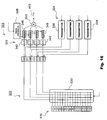
- Fig. 1 is a block diagram showing a structure of a principle portion in the first embodiment.
- an ultrasound diagnosis apparatus is composed of a probe unit and an apparatus body 12.
- the probe unit includes a probe head 10, a probe cable 14, and a cable connector which is not shown.
- the cable connector is detachably connected to the apparatus body 12, which is provided with a connector for a probe connector.
- the probe head 10 is used in contact with a surface of a living body, for example, and transmits an ultrasonic pulse and receives a reflected wave thereof in such a contact state.
- the probe head 10 includes a 2D (two-dimensional) array transducer 16 which is composed of a plurality of transducer elements 16a arranged two-dimensionally.
- the 2D array transducer 16 generates an ultrasonic beam, which is electronically scanned in a two-dimensional manner.
- the electronic scanning method in this case includes electronic sector scanning, electronic linear scanning, and on the like. With the two-dimensional electronic scanning of an ultrasonic beam, a three-dimensional space (three-dimensional echo data acquiring space) is formed.
- the 2D array transducer 16 is composed of approximately four thousand transducer elements 16a.
- a plurality of 2D sub arrays are defined with respect to the 2D array transducer 16 (which will be further described with reference to Fig. 3). These sub arrays 18 are defined such that they are closely connected with each other on the 2D array transducer 16. In the present embodiment, a plurality of sub arrays have a rectangular shape. Although the position and the shape of each sub array are fixedly determined, they may be adaptively changed.
- the probe head 10 contains a plurality of sub transmitter/receiver (transceiver) sections 20.
- the sub arrays 18 and the sub transmitter/receiver sections 20 correspond to each other on a one-to-one basis.
- 128 sub arrays are provided and 128 sub transmitter/receiver sections 20 are provided correspondingly.
- each sub transmitter/receiver section 20 of the present embodiment is provided with a group setting function, a sub phase adjusting and summing function, and a transmitting signal generating function.
- a plurality of transducer elements e.g., 16 transducer elements 16a forming a sub array 18 are grouped or divided into a plurality of groups (e.g., 4 groups).
- Each group includes a plurality of transducer elements (or a single transducer element as an exception).
- the number of transducer elements forming each group is variably set in accordance with the beam forming condition (particularly, the beam scanning direction, the beam deflecting (steering) direction, or beam shape).
- the setting pattern for a plurality of sub arrays is fixed, the setting pattern for a plurality of groups within each sub array is variable.
- a single transmitting signal which is supplied on group units, is supplied to one or a plurality of transducer elements forming a specific one group corresponding to the transmitting signal.
- one group is composed of two or more transducer elements, and a single transmitting signal is therefore supplied to the two or more transducer elements in parallel.
- a single group receiving signal is obtained for each group. Because one group is normally composed of two or more transducer elements, a group receiving signal output from a multiplexer, which will be described below with reference to Fig. 2, is obtained by adding two or more receiving signals output from two or more transducer elements.
- addition (summing) of a plurality of receiving signals obtained for each group is performed by connection of a plurality of signal lines in a multiplexer. More specifically, a plurality of receiving signals are added together due to interconnection of a plurality of signal lines extended from a plurality of transducer elements, whereby a single group receiving signal is obtained. In such a case, it is, of course, possible to perform weighted addition of a plurality of receiving signals or the like.
- one or a plurality of transducer elements within the sub array may be provided as ineffective transducer elements (i.e., a transducer element to which the group signal line is not connected). In such a case, a plurality of effective transducer elements (a transducer element to which the group signal line is connected) within the sub array are used to form a plurality of groups.
- each sub transmitter/receiver section 20 channel reduction is achieved for each sub array. For example, as a result of grouping 16 transducer elements into 4 groups, a channel reduction ratio of 1/4 can be realized.
- each sub transmitter/receiver section 20 is also provided with a sub phase adjusting and summing function as described above, and can achieve channel reduction using this function. More specifically, 4 group receiving signals, for example, obtained for each sub array 18 are subjected to a phase adjusting and summing process within the probe head 10, whereby a single sub phase adjusted and summed signal is obtained for each sub array 18.
- each sub transmitter/receiver section 20 includes the number of transmitters (4 transmitters, for example) corresponding to the number of groups forming a sub array. Accordingly, at the time of transmitting, 16 transducer elements, for example, are driven by 4 transmitting signals, for example. Specifically, a single transmitting signal is generated for one group, and thus 4 transmitting signals are supplied to 4 groups (that is, 16 transducer elements forming the sub array). Here, a channel reduction ratio of 1/4 is achieved.
- the probe head 10 has a sub transmission control section 22 for controlling the transmitting operation in the plurality of sub transmitter/receiver sections 20. Further, the probe head 10 also has a sub reception control section 24 for controlling the receiving signal process in the plurality of sub transmitter/receiver sections 20. These control sections will be described in further detail below.
- a probe cable 14 including a plurality of signal lines 100 and one or a plurality of control lines 102 is provided between the probe head 10 and the apparatus body 12. Each signal line 100 is connected to a specific sub transmitter/receiver section 20.
- Output signals from the respective A/D converters 26 are stored in parallel in a plurality of FIFO (first-in first-out) memories 28 which are disposed in parallel with each other.
- 16 FIFO memories 28 are provided for each sub array 18 so as to form 16 receiving beams simultaneously by one receiving process.
- Reading control with respect to each FIFO memory 28 is performed by a transmission/reception control section 32 which will be described below.
- the transmission/reception control section 32 determines a delay amount by controlling the reading timing with respect to each FIFO memory 28.
- 16 FIFO memories 28, which are disposed in parallel with each other, are provided for each sub array 18.
- 16 adders 30 are disposed in parallel with each other.
- Each adder 30 adds 16 signals output from the corresponding 16 specific FIFO memories 28 and outputs a receiving signal which has been phase-adjusted and summed (a main phase-adjusted and summed signal) 104.
- 16 main digital beam formers (main phase adjusting and summing circuits) 27 are provided within the apparatus body 12.
- a beam forming technology is not limited to the digital beam forming as described in Fig. 1, and analog beam forming may also be applied.
- sub phase adjusting and summing is performed within the probe head 10, and main phase adjusting and summing is performed within the apparatus body 12. With the above phase adjusting and summing processes performed in two stages, a receiving beam is finally formed.
- the electronic circuit such as a sub phase adjusting and summing circuit may also be provided within the probe connecter (not shown), as will be described below with regard to a second embodiment (Fig. 11). Further, the electronic circuit such as a sub phase adjusting and summing circuit may also be provided within the apparatus body, as will be described below with regard to a third embodiment (Fig. 12).
- the transmission/reception control section 32 within the apparatus body 12 operates in accordance with a control signal 106 supplied from a main control section (not shown) to control the operation of each element shown in Fig. 1. More specifically, within the apparatus body 12, the transmission/reception control section 32 performs writing control and reading control with respect to a plurality of FIFO memories 28 and thereby achieves dynamic focus in receiving. Further, the transmission/reception control section 32 supplies a control signal to the probe head 10 through the control line 102. In accordance with the control signal, the sub transmission control section 22 and the sub reception control section 24 control the operation of a plurality of sub transmitter/receiver sections 20 within the probe head 10.
- the control signal is also used to select patterns in the grouping process which is performed by a multiplexer as will be described below with reference to Fig. 2. It should be noted that an electric power line and a clock signal supplied from the apparatus body 12 to the probe head 10 are not shown in Fig. 1.
- Fig. 2 particularly shows a specific structure of a certain sub transmitter/receiver section 20 in the structure shown in Fig. 1.
- the plurality of sub transmitter/receiver sections 20 in Fig. 1 have the same structure.
- one sub array 18 is formed by 16 transducer elements 16a.
- One multiplexer 38 is provided corresponding to one sub array 18.
- the multiplexer 38 is a switching matrix serving as a switching means, and has the grouping function as described above.
- the multiplexer 38 performs a connecting process between 16 terminals arranged on the side of the array transducer 16 (namely, 16 element signal lines) and 4 terminals arranged on the side of the sub transmitter/receiver section 20 (namely, 4 group signal lines).
- a variety of group setting patterns can be established on the sub array 18, as will be described below with reference to Figs. 4 to 6.
- numeral 102C indicates a control signal supplied from the apparatus body to the multiplexer 38 for selecting the switching pattern.
- a plurality of multiplexers may be formed by a single switching matrix circuit.
- the multiplexer 38 further includes a plurality of switches (not shown) provided respectively at intersections between the 16 element signal lines and the 4 group signal lines. With the ON/OFF operation of each of these switches, one or a plurality of element signal lines are connected to each group signal line.
- the sub transmitter/receiver section 20 of the present embodiment includes 4 two-way transmission circuits (I/F circuits or input/output circuits) 42 used for signal transmission, a sub phase adjusting and summing circuit 34, and a transmitter section 36.
- each two-way transmission circuit 42 functions as a pulser/head amp circuit. Specifically, each two-way transmission circuit 42 supplies a transmitting signal supplied from the transmitter section 36 to the multiplexer 38 and, on the other hand, outputs a receiving signal output from the multiplexer 38 to the sub phase adjusting and summing circuit 34.
- the transmitter section 36 includes 4 memories (FIFO memories in this example) 56 and 4 D/A converters 48.
- Each FIFO memory 56 functions as a wave form generator, and the operation (the output timing, in particular) of the FIFO memory 56 is controlled by the sub transmission control section 22. Specifically, each FIFO memory 56 generates a transmitting signal waveform as a digital signal.
- a transmitting signal, which is a digital signal, output from each FIFO memory 56 is input to a D/A converter 48, where the input digital signal is converted into an analog signal.
- the transmitting signal which is now an analog signal, is transmitted to the multiplexer 38 via the two-way transmission circuit 42 described above.
- the multiplexer 38 determines one or a plurality of transducer elements forming the specific group corresponding to the transmitting signal as a destination of the signal. In this manner, 4 transmitting signals generated by the transmitter section 36 are individually supplied to the corresponding one of four groups forming a specific sub array 18.
- the sub phase adjusting and summing circuit 34 includes 4 A/D converters 46, 4 memories (FIFO memories in this example) 50, an adder 52, and a D/A converter 54.
- Each A/D converter 46 converts an input receiving signal (a group receiving signal), which is an analog signal, into a digital signal.
- the receiving signal which is now converted into a digital signal is temporarily stored in the corresponding FIFO memory 50 and is read out and supplied to the adder 52 at suitable timing for phase adjusting.
- the adder 52 sums the 4 input receiving signals.
- the sub phase adjusting and summing process is thus completed.
- the sub phase adjusted and summed signal (digital signal) obtained by this adding process is then converted into an analog signal in the D/A converter 54.
- the sub phase-adjusted and summed signal which is now an analog signal is output to the signal line 100.
- the sub phase adjusting and summing circuit 34 performs a phase adjusting and summing operation in the first stage, namely a sub phase adjusting and summing operation, and therefore corresponds to a sub digital beam former.
- the reading control for example, with respect to the 4 receiving signals is performed by the sub reception control section 24.
- a control signal 102B for reception control is input to the sub reception control section 24 and a control signal 102A for transmission control is input to the sub transmission control section 22.
- the structure of the transmitter section 36 which is illustrated in Fig. 2 is merely one example, and the transmitter section 36 may be constituted by an analog circuit, for example. In either case, delay time is set for each transmitting signal such that a transmitting beam is formed in the 2D array transducer 16 using a trigger signal supplied from the apparatus body side as a reference.
- the sub reception control section 24 may be formed as a delay data memory.
- Fig. 3 shows the array transducer 16.
- the array transducer 16 is a 2D array transducer having 50 transducer elements in the X direction and 50 transducer elements in the Y direction, for example.
- a plurality of sub arrays are defined with respect to the array transducer. More specifically, each of the plurality of sub arrays has a rectangular (square) shape and they are closely defined with no gap between each other over the whole region of the array transducer 16.
- Fig. 3 shows a representative one of these sub arrays 18.
- a plurality of groups are set for each sub array. A transmitting delay amount and a sub receiving delay amount in accordance with the focus and beam steering is provided to each group.
- a main receiving delay amount is provided for each sub array.
- a common main receiving delay amount is provided to all the plurality of transducer elements forming each sub array. Accordingly, the total delay amount obtained by adding the sub receiving delay amount and the main receiving delay amount is provided to the individual transducer elements.
- Figs. 4 to 6 show examples of group setting patterns for the sub array.
- the same grouping pattern is established for a plurality of sub arrays.
- different grouping patterns may be set for all or part of the sub arrays at the time of each transmission.
- the beam scanning direction (beam deflecting (steering) direction) corresponds to the X direction.
- Four groups G1 to G 4 are defined side by side along the X direction.
- Each of the group G1 to G4 is formed by 4 transducer elements arranged in a line along the Y direction.
- the beam scanning direction corresponds to the Y direction.
- Four groups G1 to G 4 are defined side by side along the Y direction.
- Each of the group G1 to G4 is formed by 4 transducer elements arranged in a line along the X direction.
- the beam scanning direction is set in the diagonal direction crossing the X and Y directions.
- each group has a form (shape and number of elements) which differs from any of those shown in Figs. 4 and 5.
- the group G1 is composed of 3 transducer elements arranged along the X direction
- the group G2 is composed of 4 transducer elements arranged in an L shape form and 1 transducer element located at the upper right corner of the sub array 18.
- the group G3 has the same shape as the group G2, but their directions are different by 180 degree.
- the group G4 is composed of 3 transducer elements arranged along the X direction similar to the group G1, though the group G4 is set at the lower right corner of the sub array 18 while the group G1 is set at the upper left corner of the sub array 18.
- the number of transducer elements forming each group can be variably (non-fixedly) set in accordance with the beam scanning direction, as shown in Figs. 4 to 6.
- each group When determining the form of each group, it is desirable to reduce side lobe to the greatest possible extent. By setting a larger number of groups per sub array, the degree of freedom for grouping patterns increases and more preferable beam can be formed accordingly. In this case, however, the advantage of channel reduction is reduced. It is therefore desirable to determine the number of transducer elements and the number of groups forming one sub array in accordance with the accuracy required for beam profile.
- each of the groups G1 and G4 is composed of 3 transducer elements and each of the groups G2 and G3 is composed of 5 transducer elements. It is desirable to dynamically change the grouping pattern in this manner in accordance with the beam scanning direction. This will be further described in detail with reference to Figs. 19 and 20.
- Fig. 19 shows one example in which the grouping pattern changes with a change in beam scanning direction.
- all the transducer elements forming the sub array 18 function as effective transducer elements.
- Fig. 19(A) shows a grouping pattern when the beam scanning direction is 0 degree (which is the same as the pattern shown in Fig. 4)
- Fig. 19(B) shows a grouping pattern when the beam scanning direction is 10 degree
- Fig. 19(C) shows a grouping pattern when the beam scanning direction is 20 degree
- Fig. 19(D) shows a grouping pattern when the beam scanning direction is 30 degree.
- the shape of each group and the number of transducer elements forming each group vary in accordance with the beam scanning direction, so that a preferable beam profile can be formed.
- Fig. 20 shows another example in which the grouping pattern changes with a change in beam scanning direction.
- a portion of all the transducer elements forming the sub array 18 are ineffective transducer elements 260, and the remaining transducer elements are effective transducer elements.
- Fig. 19(A) shows a grouping pattern when the beam scanning direction is 10 degree
- Fig. 19(B) shows a grouping pattern when the beam scanning direction is 20 degree
- Fig. 19(C) shows a grouping pattern when the beam scanning direction is 34 degree
- Fig. 19(D) shows a grouping pattern when the beam scanning direction is 45 degree.
- the shape of each group and the number of transducer elements forming each group vary in accordance with the beam scanning direction, and the number of ineffective transducer elements also varies, so that a preferable beam profile can be formed.
- Fig. 7 conceptually shows a relationship between the sub delay amount in the sub phase adjusting and summing process and the main delay amount in the main phase adjusting and summing process.
- the sub delay amount is a relative delay amount which is determined for each group, and the main delay amount corresponds to an offset delay amount with respect to each sub array as a whole.
- the receiving delay amount for each group can be divided into the sub delay amount and the main delay amount corresponding to the two-stage phase adjusting and summing process.
- the transmitting delay amount for each group cannot be divided in that manner.
- numeral 206 indicates a line having an equal distance from a focus F, and such a line 206 can be regarded as a virtual sound source having a scope. If the transducer elements are arranged on this line 206, phases of the ultrasound transmitted from the transducer elements can be completely matched on the focus F, and phases of ultrasound (reflected waves) received by the transducer elements can also be matched completely. In actual practice, however, a plurality of transducer elements are arranged on an actual transducer plane indicated by numeral 200, and the focus F may move.
- Known electronic focusing technologies are therefore applied so as to match the phases of ultrasound transmitted from each transducer element with respect to the focus F and also match the phases of receiving signals output from the transducer elements. In the present embodiment, an electronic delay process with respect to a transmitting signal and a receiving signal is performed for each group in each sub array.
- numerals 202 and 204 indicate a partial opening corresponding to a sub array. According to the geometrical relationship shown in Fig. 7, the largest delay time is given to the left end portion (a group on the left end side) of the partial openings 202 and 204, and the smallest delay time is given to the right end portion (a group on the right end side) of the partial openings 202 and 204.
- Lines 208 and 210 are drawn at equal distances from the focus F, respectively, and pass through the right ends of the partial openings 202 and 204, respectively in the example shown in Fig. 7. With respect to the partial opening 202, the distance between the line 208 and the line 206 corresponds to the main delay amount, which is indicated by T2.
- the sub delay amount T1 is shown between the actual transducer plane 200 and the line 208.
- the main delay amount is common over the whole of the partial opening 202, whereas the sub delay amount is different depending on the group position (e.g., the center position of the group) within the partial opening 202.
- the main delay amount is represented by T4 and the sub delay amount on the left end is represented by T3.
- the sub delay time is individually determined for each group in each sub array in the present embodiment, it is also possible to set the same sub delay time with respect to the transducer elements having the same element number (the same element position or the same element address) for a plurality of sub arrays. With such a structure, although beam focusing property is lowered, control can be simplified.
- Fig. 8 shows a relationship between the probe head 10 and a part of the three-dimensional echo data acquiring space.
- Numeral 224 indicates a transmitting beam.
- 16 receiving beams 228 are simultaneously formed with respect to one transmitting beam 224.
- a matrix 222 which is schematically shown as a bottom surface of the three-dimensional echo data acquiring space 220 represents addresses of the receiving beam 228.
- 16 addresses are shown in the X direction and 16 addresses are shown in the Y direction, which results in total of 256 addresses for the receiving beam.
- the transmitting beam 224 has a broad beam profile covering 16 receiving beams 228.
- each receiving beam 228 has a sharp beam profile.
- Figs. 9 and 10 show tables indicating transmitting and receiving conditions.
- the grouping pattern, a set of transmitting delay amounts, and a set of receiving sub delay amounts are determined for each sub array.
- the set of transmitting delay amounts in this example, is composed of four delay amounts given to four groups forming a sub array.
- the set of receiving sub delay amounts is composed, in this example, of four sub delay amounts given to four groups forming a sub array.
- the value of each sub delay amount forming the set of receiving sub delay amounts may be dynamically varied in accordance with the depth of a receiving point.
- Fig. 10 shows a set of receiving main delay amounts 230 for each receiving beam which is set for each transmitting beam address.
- the receiving main delay amount set 230 is composed of 128 main delay amounts, and each main delay amount is dynamically variable in accordance with the depth of a receiving point so as to achieve dynamic focus in receiving.
- the transmitter section 36 shown in Fig. 2 generates a low voltage transmitting signal for each group.
- the voltage of a transmitting signal is approximately between several volt and ten-odd volt, such as ⁇ 4.5V and ⁇ 9V.
- a layered type transducer element for example, is used as the transducer element 16a, it is possible to reduce the electrical impedance thereof to approximately several hundred ohms.
- the transducer elements may be driven with a high voltage as in the conventional manner.
- the advantage of remarkably reducing the number of signal lines forming the probe cable 14 can be achieved.
- the transmitter section is provided within the probe head 10, the necessity of supplying a transmitting signal from the apparatus body 12 side for each transmission channel, namely for each group, can be eliminated, and the apparatus body 12 need only to remotely control the transmitter section within the probe head 12.
- 16 receiving beams are simultaneously formed for one transmitting beam, namely because 16 pieces of receiving information can be obtained in one transmitting/receiving process, the advantage of increasing the volume rate can be achieved.
- a three-dimensional ultrasonic image, or a tomography image corresponding to a cross section when the three-dimensional data acquiring space is observed from an arbitrary direction is formed.
- a multiplexer is used for performing grouping (channel reduction) within the probe head.
- the sub phase adjusting and summing process is, however, performed within the connector (Fig. 11) or the apparatus body (Fig. 12), not within the probe head.
- various grouping patterns including the grouping patterns shown in Figs. 4, 5, 6, 19, and 20 can be established.
- Fig. 11 shows the second embodiment of the present invention.
- An ultrasound diagnosis apparatus is roughly formed by a probe unit and an apparatus body 312.
- the probe unit is composed of a probe head 310, a probe cable 314A, and a cable connector 314B.
- the probe cable 314A includes a plurality of signal lines which will be described below.
- the cable connector 314B which has a box shape, is detachably connected to the apparatus body 312.
- an electronic circuit which will be described below is contained within the cable connector 314B.
- the electronic circuit may be provided within the apparatus body, as will be described with reference to Fig. 12.
- the probe head 310 is used in contact with a surface of a living body, for example, for performing transmission and reception of ultrasound.
- the probe head 310 includes a 2D array transducer 316 which is composed of a great number of (about 4000, for example) transducer elements 316a.
- An ultrasonic beam is formed by the 2D array transducer 316 and is electronically scanned in a two-dimensional manner.
- a plurality of 2D sub arrays 318 are defined with respect to the 2D array transducer 316 (see Fig. 3). In the present embodiment, 128 sub arrays are defined. In the present embodiment, each sub array is composed of 16 transducer elements 316a. The plurality of sub arrays 318 are closely coupled with each other on the 2D array transducer 316. Each sub array 318 has a rectangular shape and is defined fixedly. It is also possible, however, to adaptively vary the form of each sub array in accordance with the transmission/reception conditions (particularly the beam scanning direction), for example.
- 128 channel reduction units 320 are provided corresponding to 128 sub arrays 318.
- one sub array 318 corresponds to one channel reduction unit 320.
- Each channel reduction unit 320 has a function of grouping 16 transducer elements forming a specific sub array corresponding thereto into 4 groups. With this function, the channel reduction ratio of 1/4 is achieved.
- 4 transmitting signals supplied from the apparatus body 12 side are supplied to the four groups, respectively. Because one group is normally composed of two or more transducer elements, one transmitting signal is supplied to two or more transducer elements in parallel. With respect to receiving, 16 receiving signals are combined into 4 group receiving signals.
- one group is normally composed of two or more transducer elements, two or more receiving signals are summed to generate one group receiving signal.
- a summing process of a plurality of receiving signals can be achieved by connecting a plurality of signal lines in the multiplexer.
- a plurality of receiving signals may be subjected to weighted addition.
- the probe cable 314A includes a plurality of signal lines 400. Specifically, 4 signal lines 400 are provided for each sub array 318, and a total of 128 x 4 signal lines 400 are provided for the whole 2D array transducer 316.
- One or more control lines 402A are also included in the probe cable 314A separately from these signal lines 400.
- the control line 402A is used to control the operation of each element within the probe head 310. It should be noted that a power supply line supplied from the apparatus body 312 side to the probe head 310 or the like is not shown in Fig. 11.
- a plurality of transmission/reception modules 322 are provided within the cable connector 314B.
- One transmission/reception module 322 is provided for each sub array, and, in the present embodiment, a total of 128 transmission/reception modules 322 are provided within the cable connector 314B.
- Each transmission/reception module 322 includes the transmitter section 324 and a sub phase adjusting and summing circuit 326.
- the transmitter section 324 includes 4 transmitters which output 4 transmitting signals, respectively.
- the 4 transmitting signals are supplied to the corresponding channel reduction unit 320 via the probe cable, and then supplied to the 4 groups, respectively.
- the sub phase adjusting and summing circuit 326 performs, as a phase adjusting and summing process at the first stage, a sub phase adjusting and summing process with respect to the 4 group receiving signals which are input. As a result, these 4 receiving signals are combined into one sub phase adjusted and summed signal, which is indicated by numeral 403.
- a main phase adjusting and summing circuit 328 and a transmission/reception control section 329 are provided within the apparatus body 312.
- the main phase adjusting and summing circuit 328 performs a main phase adjusting and summing process with respect to 128 phase adjusted and summed signals obtained corresponding to the 128 sub arrays.
- the main phase adjusting and summing circuit 328 performs a phase adjusting and summing process at the second stage, thereby obtaining a main phase adjusted and summed signal 404.
- the phase adjusting and summing means is composed of a plurality of sub beam formers and a single main beam former.
- the receiving signals are transmitted between the cable connector 314B and the apparatus body 312 basically using 128 transmission lines. This provides an advantage that the signal transmitting method for existing ultrasound diagnosis apparatuses can be used as it is.
- a beam former provided in an existing ultrasonic diagnosis apparatus can be used as the main phase adjusting and summing circuit 328.
- the operation of the transmission/reception control section 329 is controlled by a main control section (not shown), to thereby control the operation of each element shown in Fig. 11.
- the transmission/reception control section 329 outputs a control signal 402B to each element within the probe connector 314B and outputs a control signal 402A to each element within the probe head 310.
- main phase adjusting and summing circuit 328 While a single main phase adjusting and summing circuit 328 is provided within the apparatus body 312 in the embodiment shown in Fig. 11, any desired number of main phase adjusting and summing circuits 328 may be provided in parallel, similar to the first embodiment described above, to simultaneously form a plurality of receiving beams in one transmitting process.
- Fig. 12 shows a third embodiment of the present invention, in which elements similar to those in Fig. 11 are designated by similar numerals and therefore will not be described again.
- the plurality of transmission/reception modules 322 shown in Fig. 11 are provided within the apparatus body 312.
- the probe connector is omitted in Fig. 12.
- This structure can similarly provide an advantage of reducing the number of signal lines 400 by means of channel reduction performed within the probe head 310.
- the transmission/reception control section 329 controls the operation of each element shown in Fig. 12, and supplies a control signal to the probe head 310.
- a transmitting signal may be transmitted as a voltage signal and a receiving signal may be transmitted as a current signal.
- the transmitting signal may be a low voltage signal in the range of several V to ten-odd V, for example, such as ⁇ 4.5V or ⁇ 9V.
- V ten-odd
- a signal of high voltage such as 100V, for example, may also be used as the transmitting signal.
- the array transducer 316 is formed as a 2D array transducer.
- a plurality of sub arrays 318 are defined on the array transducer 316 (see Fig. 3).
- Each sub array 318 has a rectangular shape.
- grouping patterns are set in accordance with the transmission and reception conditions for each sub array 318 (see Figs. 4 to 6).
- a sub delay amount is set for each group, and a main delay amount is set for each sub array, in accordance with the conditions shown in Fig. 7.
- the multiplexer 330 is connected to the sub array 318.
- the multiplexer 330 is a switching matrix, and therefore functions as a switching means or a group setting means.
- the multiplexer 330 has 16 terminals on the side of the sub array 318 and 4 terminals on the side of the probe cable. Accordingly, any desired line connection can be achieved between these 16 terminals and 4 terminals, which allows the setting of desired grouping patterns.
- the number of transducer elements forming each group is variably set in the present embodiment, the number of transducer elements can be set the same for all of the groups. Further, the same grouping pattern may be used for a plurality of sub arrays, or a desired grouping pattern may be set for each sub array in accordance with the position of the sub array and the transmission/reception conditions.
- two-way transmission circuits 332 are provided in the channel reduction unit 320.
- the two-way transmission circuit 332 has a function of transmitting a receiving signal and a transmitting signal, and operates as a current to voltage conversion circuit, for example.
- Various structures can be used for the two-way transmission circuit 332 and a two-way transmission circuit 334 which will be described below.
- a plurality of transmitters 336 forming a transmitter section 324 are provided in the transmission/reception module 322.
- 4 transmitters 336 are provided and generate 4 transmitting signals. These transmitting signals are supplied to the probe head side via 4 transmission circuits 334, respectively, provided within the transmission/reception module 332.
- Each of the two-way transmission circuits 334 functions as a terminal circuit for accepting a receiving signal and also as a circuit for transmitting a transmitting signal.
- the transmission/reception module 322 includes a sub phase adjusting and summing circuit 326 which functions as a sub beam former.
- the sub phase adjusting and summing circuit 326 is formed as an analog phase adjusting and summing circuit. More specifically, the sub phase adjusting and summing circuit 326 includes a switching matrix 330 and a delay line 341.
- the delay line 341 has a great number of taps corresponding to respective delay amounts, and the switching matrix 330 supplies each of the 4 input receiving signals to a tap which corresponds to the receiving sub delay amount of the signal, whereby a sub phase adjusting and summing process is achieved in an analog manner. With the above process, a sub phase adjusted and summed signal 403 is generated.
- the switching matrix 330 includes a plurality of switches (not shown) provided respectively at intersections between 16 element signal lines and 4 group signal lines. With the ON/OFF operation of each of these switches, one or a plurality of element signal lines are connected to each group signal line.
- a plurality of two-way transmission circuits 340 are provided within a transmission/reception module 322. These transmission circuits 340 are directly connected to the multiplexer 330. Each transmission circuit 340 may function as a pulser used for transmission and a head amp circuit used for reception.
- the sub phase adjusting and summing circuit 326 is formed in the form of a digital beam former.
- the sub phase adjusting and summing circuit 326 includes 4 A/D converters 342, 4 memories 346, an adder 350, and a timing controller 348.
- a receiving signal (a group receiving signal) output from each transmission circuit 334 is supplied to the corresponding one of A/D converters 342, where the input analog signal is converted into a digital signal, which is then stored temporarily in the memory 346.
- the timing controller 348 controls the signal reading timing with respect to the 4 memories 346 to thereby assign delay time to each signal.
- the 4 signals thus read out from the 4 memories 346 are summed in the adder 350.
- a sub phase adjusted and summed signal 403 is obtained in the form of a digital signal.
- the example structure shown in Fig. 16 is the same as the example structure shown in Fig. 15 in that the transmission/reception module 322 includes a sub digital beam former, and differs from the example structure of Fig. 15 in that 4 two-way transmission circuits 340 are provided only on the side of transmission/reception module 322.
- each transmission circuit 340 functions as a pulser/head amp circuit similar to each transmission circuit 340 shown in Fig. 14, and is directly connected to the multiplexer 330.
- the sub phase adjusting and summing circuit 326 is formed in the form of an analog phase adjusting and summing circuit which uses a CCD device. More specifically, 4 CCDs and 4 switching circuits 354 are provided corresponding to 4 receiving signals (4 group receiving signals), and the controller 360 supplies a clock signal to the CCDs 352 and supplies a control signal to the switching circuits 354.
- an input signal is sequentially transmitted in synchronization with a clock and is extracted from a position which is specified by the controller 360.
- the extracted signal is output to the adder 358 via an amplifier 356.
- the 4 signals which have been subjected to the delay process are summed in the adder 358, so that a sub phase adjusted and summed signal 403 is generated in the form of an analog signal.
- the controller 360 controls a plurality of sub phase adjusting and summing circuits as a whole.
- the number of signal lines for transmitting within the probe cable can be reduced.
- preferable beams can be formed.
- the number of transducer elements forming each group can be varied, so that side lobes can be reduced or a preferable beam profile can be obtained.
Landscapes
- Engineering & Computer Science (AREA)
- Physics & Mathematics (AREA)
- Radar, Positioning & Navigation (AREA)
- Remote Sensing (AREA)
- Computer Networks & Wireless Communication (AREA)
- General Physics & Mathematics (AREA)
- Acoustics & Sound (AREA)
- Multimedia (AREA)
- Ultra Sonic Daignosis Equipment (AREA)
- Investigating Or Analyzing Materials By The Use Of Ultrasonic Waves (AREA)
Applications Claiming Priority (4)
| Application Number | Priority Date | Filing Date | Title |
|---|---|---|---|
| JP2003181104 | 2003-06-25 | ||
| JP2003181070 | 2003-06-25 | ||
| JP2003181104 | 2003-06-25 | ||
| JP2003181070 | 2003-06-25 |
Publications (3)
| Publication Number | Publication Date |
|---|---|
| EP1491913A2 true EP1491913A2 (de) | 2004-12-29 |
| EP1491913A3 EP1491913A3 (de) | 2005-03-09 |
| EP1491913B1 EP1491913B1 (de) | 2006-09-27 |
Family
ID=33422200
Family Applications (1)
| Application Number | Title | Priority Date | Filing Date |
|---|---|---|---|
| EP04013962A Expired - Lifetime EP1491913B1 (de) | 2003-06-25 | 2004-06-15 | Diagnostische ultraschall-bildgebende Vorrichtung mit einem 2D Schallkopf mit variablen Subarrays |
Country Status (4)
| Country | Link |
|---|---|
| US (1) | US7217243B2 (de) |
| EP (1) | EP1491913B1 (de) |
| CN (1) | CN1575772B (de) |
| DE (1) | DE602004002523T2 (de) |
Cited By (12)
| Publication number | Priority date | Publication date | Assignee | Title |
|---|---|---|---|---|
| WO2008002464A2 (en) | 2006-06-23 | 2008-01-03 | Teratech Corporation | Ultrasound 3d imaging system |
| EP1936404A1 (de) | 2006-12-18 | 2008-06-25 | Aloka Co., Ltd. | Diagnostisches Ultraschallgerät |
| WO2010031057A1 (en) * | 2008-09-15 | 2010-03-18 | Teratech Corporation | Ultrasound 3d imaging system |
| US8096951B2 (en) | 2007-06-28 | 2012-01-17 | General Electric Company | Transmit beamforming in 3-dimensional ultrasound |
| EP1980872A3 (de) * | 2007-04-13 | 2013-04-24 | Medison Co., Ltd. | System zur Bildung von Ultraschallbildern und Verfahren zur Bildung von Abtastliniendaten |
| WO2013168045A1 (en) * | 2012-05-09 | 2013-11-14 | Koninklijke Philips N.V. | Ultrasound transducer arrays with variable patch geometries |
| WO2014182567A1 (en) * | 2013-05-08 | 2014-11-13 | General Electric Company | Ultrasound probe with dynamic focus and associated systems and methods |
| EP2860547A1 (de) * | 2013-10-08 | 2015-04-15 | Samsung Electronics Co., Ltd | Vorrichtung und Verfahren zur Strahlformung |
| US10080544B2 (en) | 2008-09-15 | 2018-09-25 | Teratech Corporation | Ultrasound 3D imaging system |
| US10426435B2 (en) | 2008-09-15 | 2019-10-01 | Teratech Corporation | Ultrasound 3D imaging system |
| WO2020053309A1 (fr) * | 2018-09-13 | 2020-03-19 | Moduleus | Dispositif d'imagerie ultrasonore |
| WO2021219402A1 (fr) * | 2020-04-30 | 2021-11-04 | Moduleus | Dispositif d'imagerie ultrasonore |
Families Citing this family (47)
| Publication number | Priority date | Publication date | Assignee | Title |
|---|---|---|---|---|
| JP2003093389A (ja) * | 2001-09-27 | 2003-04-02 | Hitachi Medical Corp | 超音波診断装置 |
| US20050148879A1 (en) * | 2003-12-19 | 2005-07-07 | Siemens Medical Solutions Usa, Inc. | Mode dependent tunable transducers and methods of use |
| DE102004059856B4 (de) * | 2004-12-11 | 2006-09-14 | Fraunhofer-Gesellschaft zur Förderung der angewandten Forschung e.V. | Verfahren zur zerstörungsfreien Untersuchung eines Prüfkörpers mittels Ultraschall |
| JP4426472B2 (ja) * | 2005-01-19 | 2010-03-03 | アロカ株式会社 | 超音波診断装置 |
| US7862512B2 (en) * | 2005-08-29 | 2011-01-04 | Unex Corporation | Blood vessel endothelium function evaluating apparatus provided with an electronic control device |
| WO2008051639A2 (en) | 2006-10-25 | 2008-05-02 | Maui Imaging, Inc. | Method and apparatus to produce ultrasonic images using multiple apertures |
| US7775982B2 (en) * | 2006-12-15 | 2010-08-17 | General Electric Company | Method and system for sub-aperture processing |
| US7798967B2 (en) * | 2006-12-19 | 2010-09-21 | Aloka Co., Ltd. | Ultrasound diagnosis apparatus |
| JP5367247B2 (ja) * | 2007-09-28 | 2013-12-11 | 富士フイルム株式会社 | 超音波撮像装置及び超音波撮像方法 |
| US9282945B2 (en) * | 2009-04-14 | 2016-03-15 | Maui Imaging, Inc. | Calibration of ultrasound probes |
| US9788813B2 (en) | 2010-10-13 | 2017-10-17 | Maui Imaging, Inc. | Multiple aperture probe internal apparatus and cable assemblies |
| JP5555416B2 (ja) * | 2007-10-25 | 2014-07-23 | 三星メディソン株式会社 | 超音波診断装置及びスキャンラインデータ形成方法 |
| GB2457240B (en) * | 2008-02-05 | 2013-04-10 | Fujitsu Ltd | Ultrasound probe device and method of operation |
| JP5666446B2 (ja) | 2008-08-08 | 2015-02-12 | マウイ イマギング,インコーポレーテッド | マルチアパーチャ方式の医用超音波技術を用いた画像形成方法及びアドオンシステムの同期方法 |
| EP2419022B1 (de) | 2009-04-14 | 2019-11-06 | Maui Imaging, Inc. | Ausrichtungsvorrichtung für ultraschall-array mit mehreren aperturen |
| JP5315153B2 (ja) * | 2009-07-21 | 2013-10-16 | 日立アロカメディカル株式会社 | 超音波診断装置 |
| JP5436965B2 (ja) * | 2009-07-28 | 2014-03-05 | 日立アロカメディカル株式会社 | 超音波診断装置 |
| WO2011092718A1 (en) * | 2010-01-28 | 2011-08-04 | Indian Institute Of Technology Ht P.O. | Technique for imaging using array of focused virtual sources using phased excitation |
| EP2536339B1 (de) | 2010-02-18 | 2024-05-15 | Maui Imaging, Inc. | Punktquellenübertragung und schallgeschwindigkeitskorrektur mittels ultraschallbildgebung mit mehreren blenden |
| US9668714B2 (en) | 2010-04-14 | 2017-06-06 | Maui Imaging, Inc. | Systems and methods for improving ultrasound image quality by applying weighting factors |
| US9575165B2 (en) * | 2010-05-25 | 2017-02-21 | General Electric Company | Ultrasound probe and ultrasound imaging system |
| WO2012014120A1 (en) | 2010-07-30 | 2012-02-02 | Koninklijke Philips Electronics N.V. | Display and export of individual biplane images |
| CN103037774B (zh) * | 2010-07-30 | 2015-11-25 | 皇家飞利浦电子股份有限公司 | 自动扫掠和输出3d体积的2d超声图像 |
| KR101906838B1 (ko) | 2010-10-13 | 2018-10-11 | 마우이 이미징, 인코포레이티드 | 오목한 초음파 트랜스듀서들 및 3d 어레이들 |
| IT1403296B1 (it) * | 2010-12-28 | 2013-10-17 | St Microelectronics Srl | Sistema di immagine ad ultrasuoni con dati in 4d e corrispondente processo di controllo |
| TW201232476A (en) * | 2011-01-27 | 2012-08-01 | Univ Nat Taiwan | Detection system and signal processing method thereof |
| JP5984542B2 (ja) * | 2011-08-08 | 2016-09-06 | キヤノン株式会社 | 被検体情報取得装置、被検体情報取得システム、表示制御方法、表示方法、及びプログラム |
| JP5892745B2 (ja) | 2011-08-18 | 2016-03-23 | 株式会社東芝 | 超音波診断装置 |
| EP2785253B1 (de) | 2011-12-01 | 2023-11-15 | Maui Imaging, Inc. | Bewegungserfassung unter verwendung von ping-basiertem doppler-ultraschall mit mehreren aperturen |
| JP2015503404A (ja) | 2011-12-29 | 2015-02-02 | マウイ イマギング,インコーポレーテッド | 任意経路のmモード超音波イメージング |
| CN104135937B (zh) | 2012-02-21 | 2017-03-29 | 毛伊图像公司 | 使用多孔超声确定材料刚度 |
| US9239317B2 (en) | 2012-05-22 | 2016-01-19 | General Electric Company | System and method for ultrasonic testing with a single channel ultrasonic test unit |
| US10269340B2 (en) | 2012-06-15 | 2019-04-23 | University Of Southern California | Ultrasound beamformer with individual array element multiplexers |
| WO2014026185A1 (en) | 2012-08-10 | 2014-02-13 | Maui Imaging, Inc. | Calibration of multiple aperture ultrasound probes |
| CN104582582B (zh) | 2012-08-21 | 2017-12-15 | 毛伊图像公司 | 超声成像系统存储器架构 |
| JP6072932B2 (ja) * | 2012-12-18 | 2017-02-01 | フィリップス ライティング ホールディング ビー ヴィ | センサからのパルスの送信の制御 |
| JP5504357B1 (ja) * | 2013-01-09 | 2014-05-28 | 日立アロカメディカル株式会社 | 超音波診断装置 |
| US9510806B2 (en) | 2013-03-13 | 2016-12-06 | Maui Imaging, Inc. | Alignment of ultrasound transducer arrays and multiple aperture probe assembly |
| US9883848B2 (en) | 2013-09-13 | 2018-02-06 | Maui Imaging, Inc. | Ultrasound imaging using apparent point-source transmit transducer |
| US10401493B2 (en) | 2014-08-18 | 2019-09-03 | Maui Imaging, Inc. | Network-based ultrasound imaging system |
| JP6038259B1 (ja) * | 2015-10-20 | 2016-12-07 | 株式会社日立製作所 | 超音波診断装置 |
| CN113729764A (zh) | 2016-01-27 | 2021-12-03 | 毛伊图像公司 | 具有稀疏阵列探测器的超声成像 |
| CN105842347B (zh) * | 2016-03-29 | 2019-03-15 | 河海大学常州校区 | 一种时分复用的大功率相控阵超声信号发生装置 |
| JP6736723B2 (ja) * | 2019-04-25 | 2020-08-05 | キヤノン株式会社 | 光音響トモグラフィの受信データ処理装置 |
| JP2022068431A (ja) * | 2020-10-22 | 2022-05-10 | 富士フイルムヘルスケア株式会社 | 超音波探触子 |
| US20220313207A1 (en) * | 2021-04-01 | 2022-10-06 | Bfly Operations, Inc. | Apparatuses and methods for configuring ultrasound devices |
| CN114343708B (zh) * | 2022-01-05 | 2024-05-14 | 京东方科技集团股份有限公司 | 一种超声波阵列基板和驱动方法、检测系统和应用方法 |
Citations (6)
| Publication number | Priority date | Publication date | Assignee | Title |
|---|---|---|---|---|
| US5229933A (en) * | 1989-11-28 | 1993-07-20 | Hewlett-Packard Company | 2-d phased array ultrasound imaging system with distributed phasing |
| US5349262A (en) * | 1994-02-22 | 1994-09-20 | Hewlett-Packard Company | Phased array ultrasound imaging system with dynamic elevation focusing |
| US5563346A (en) * | 1994-02-21 | 1996-10-08 | Siemens Aktiengesellschaft | Method and device for imaging an object using a two-dimensional ultrasonic array |
| US5832923A (en) * | 1996-12-11 | 1998-11-10 | General Electric Company | Utrasound imaging system architecture employing switched transducer elements |
| US6111816A (en) * | 1997-02-03 | 2000-08-29 | Teratech Corporation | Multi-dimensional beamforming device |
| US20030018260A1 (en) * | 2001-06-20 | 2003-01-23 | Erikson Kenneth R. | Orthogonally reconfigurable integrated matrix acoustical array |
Family Cites Families (17)
| Publication number | Priority date | Publication date | Assignee | Title |
|---|---|---|---|---|
| US5617862A (en) * | 1995-05-02 | 1997-04-08 | Acuson Corporation | Method and apparatus for beamformer system with variable aperture |
| JPH09322896A (ja) | 1996-06-05 | 1997-12-16 | Matsushita Electric Ind Co Ltd | 超音波診断装置 |
| US5897501A (en) * | 1997-05-07 | 1999-04-27 | General Electric Company | Imaging system with multiplexer for controlling a multi-row ultrasonic transducer array |
| US6193663B1 (en) * | 1997-12-18 | 2001-02-27 | Acuson Corporation | Diagnostic ultrasound imaging method and system with improved frame rate |
| US6013032A (en) * | 1998-03-13 | 2000-01-11 | Hewlett-Packard Company | Beamforming methods and apparatus for three-dimensional ultrasound imaging using two-dimensional transducer array |
| US5997479A (en) * | 1998-05-28 | 1999-12-07 | Hewlett-Packard Company | Phased array acoustic systems with intra-group processors |
| US6089096A (en) * | 1998-07-01 | 2000-07-18 | Aloka Co., Ltd. | Elevation focusing by beamformer channel sharing |
| US6102863A (en) * | 1998-11-20 | 2000-08-15 | Atl Ultrasound | Ultrasonic diagnostic imaging system with thin cable ultrasonic probes |
| US6174286B1 (en) * | 1998-11-25 | 2001-01-16 | Acuson Corporation | Medical diagnostic ultrasound method and system for element switching |
| US6540862B1 (en) * | 1999-01-28 | 2003-04-01 | Meadwestvaco Corporation | Method and apparatus for enhancing film adhesion when extruding polyethylene terephthalate onto paperboard |
| JP3482361B2 (ja) | 1999-10-04 | 2003-12-22 | アロカ株式会社 | 超音波診断装置 |
| JP2001276064A (ja) | 2000-03-31 | 2001-10-09 | Matsushita Electric Ind Co Ltd | 超音波診断装置のビームフォーマ |
| US6468216B1 (en) * | 2000-08-24 | 2002-10-22 | Kininklijke Philips Electronics N.V. | Ultrasonic diagnostic imaging of the coronary arteries |
| US6582367B1 (en) * | 2000-09-15 | 2003-06-24 | Koninklijke Philips Electronics N.V. | 2D ultrasonic transducer array for two dimensional and three dimensional imaging |
| US6491634B1 (en) * | 2000-10-13 | 2002-12-10 | Koninklijke Philips Electronics N.V. | Sub-beamforming apparatus and method for a portable ultrasound imaging system |
| US6537219B2 (en) * | 2001-04-04 | 2003-03-25 | Koninklijke Philips Electronics N.V. | Static focus ultrasound apparatus and method |
| JP2003290228A (ja) * | 2002-03-29 | 2003-10-14 | Ge Medical Systems Global Technology Co Llc | 2次元アレイ超音波探触子の駆動方法および超音波診断装置 |
-
2004
- 2004-06-15 EP EP04013962A patent/EP1491913B1/de not_active Expired - Lifetime
- 2004-06-15 DE DE602004002523T patent/DE602004002523T2/de not_active Expired - Lifetime
- 2004-06-16 US US10/869,152 patent/US7217243B2/en not_active Expired - Fee Related
- 2004-06-23 CN CN200410050143.XA patent/CN1575772B/zh not_active Expired - Fee Related
Patent Citations (6)
| Publication number | Priority date | Publication date | Assignee | Title |
|---|---|---|---|---|
| US5229933A (en) * | 1989-11-28 | 1993-07-20 | Hewlett-Packard Company | 2-d phased array ultrasound imaging system with distributed phasing |
| US5563346A (en) * | 1994-02-21 | 1996-10-08 | Siemens Aktiengesellschaft | Method and device for imaging an object using a two-dimensional ultrasonic array |
| US5349262A (en) * | 1994-02-22 | 1994-09-20 | Hewlett-Packard Company | Phased array ultrasound imaging system with dynamic elevation focusing |
| US5832923A (en) * | 1996-12-11 | 1998-11-10 | General Electric Company | Utrasound imaging system architecture employing switched transducer elements |
| US6111816A (en) * | 1997-02-03 | 2000-08-29 | Teratech Corporation | Multi-dimensional beamforming device |
| US20030018260A1 (en) * | 2001-06-20 | 2003-01-23 | Erikson Kenneth R. | Orthogonally reconfigurable integrated matrix acoustical array |
Cited By (30)
| Publication number | Priority date | Publication date | Assignee | Title |
|---|---|---|---|---|
| EP2037814A2 (de) * | 2006-06-23 | 2009-03-25 | Teratech Corporation | 3d-ultraschallbildgebungssystem |
| WO2008002464A2 (en) | 2006-06-23 | 2008-01-03 | Teratech Corporation | Ultrasound 3d imaging system |
| EP3376253A3 (de) * | 2006-06-23 | 2019-02-27 | Teratech Corporation | 3d-ultraschallbildgebungssystem |
| EP2037814A4 (de) * | 2006-06-23 | 2013-04-17 | Teratech Corp | 3d-ultraschallbildgebungssystem |
| US8551000B2 (en) | 2006-06-23 | 2013-10-08 | Teratech Corp. | Ultrasound 3D imaging system |
| US9089304B2 (en) | 2006-06-23 | 2015-07-28 | Teratech Corporation | Ultrasound transducer subarray system and method |
| EP1936404A1 (de) | 2006-12-18 | 2008-06-25 | Aloka Co., Ltd. | Diagnostisches Ultraschallgerät |
| US8968202B2 (en) | 2007-04-13 | 2015-03-03 | Medison Co., Ltd. | System of forming ultrasound image and method of forming scan line data |
| EP1980872A3 (de) * | 2007-04-13 | 2013-04-24 | Medison Co., Ltd. | System zur Bildung von Ultraschallbildern und Verfahren zur Bildung von Abtastliniendaten |
| US8096951B2 (en) | 2007-06-28 | 2012-01-17 | General Electric Company | Transmit beamforming in 3-dimensional ultrasound |
| US11559277B2 (en) | 2008-09-15 | 2023-01-24 | Teratech Corporation | Ultrasound 3D imaging system |
| US10426435B2 (en) | 2008-09-15 | 2019-10-01 | Teratech Corporation | Ultrasound 3D imaging system |
| WO2010031057A1 (en) * | 2008-09-15 | 2010-03-18 | Teratech Corporation | Ultrasound 3d imaging system |
| US10080544B2 (en) | 2008-09-15 | 2018-09-25 | Teratech Corporation | Ultrasound 3D imaging system |
| US11391838B2 (en) | 2012-05-09 | 2022-07-19 | Koninklijke Philips N.V. | Ultrasound transducer arrays with variable patch geometries |
| WO2013168045A1 (en) * | 2012-05-09 | 2013-11-14 | Koninklijke Philips N.V. | Ultrasound transducer arrays with variable patch geometries |
| US9739885B2 (en) | 2012-05-09 | 2017-08-22 | Koninklijke Philips N.V. | Ultrasound transducer arrays with variable patch geometries |
| RU2638967C2 (ru) * | 2012-05-09 | 2017-12-19 | Конинклейке Филипс Н.В. | Матрицы ультразвуковых преобразователей с переменными геометриями участков поверхности |
| US10168428B2 (en) | 2012-05-09 | 2019-01-01 | Koninklijke Philips N.V. | Ultrasound transducer arrays with variable patch geometries |
| CN105339808A (zh) * | 2013-05-08 | 2016-02-17 | 通用电气公司 | 采用动态聚焦的超声探头以及关联系统和方法 |
| US9239375B2 (en) | 2013-05-08 | 2016-01-19 | General Electric Company | Ultrasound probe with dynamic focus and associated systems and methods |
| WO2014182567A1 (en) * | 2013-05-08 | 2014-11-13 | General Electric Company | Ultrasound probe with dynamic focus and associated systems and methods |
| EP2860547A1 (de) * | 2013-10-08 | 2015-04-15 | Samsung Electronics Co., Ltd | Vorrichtung und Verfahren zur Strahlformung |
| WO2020053309A1 (fr) * | 2018-09-13 | 2020-03-19 | Moduleus | Dispositif d'imagerie ultrasonore |
| FR3086063A1 (fr) * | 2018-09-13 | 2020-03-20 | Moduleus | Dispositif d'imagerie ultrasonore |
| CN112672832A (zh) * | 2018-09-13 | 2021-04-16 | 莫杜莱斯公司 | 超声成像设备 |
| CN112672832B (zh) * | 2018-09-13 | 2022-01-07 | 莫杜莱斯公司 | 超声成像设备 |
| US12066532B2 (en) | 2018-09-13 | 2024-08-20 | Moduleus | Ultrasound imaging device |
| WO2021219402A1 (fr) * | 2020-04-30 | 2021-11-04 | Moduleus | Dispositif d'imagerie ultrasonore |
| FR3109826A1 (fr) * | 2020-04-30 | 2021-11-05 | Moduleus | Dispositif d'imagerie ultrasonore |
Also Published As
| Publication number | Publication date |
|---|---|
| DE602004002523T2 (de) | 2007-05-10 |
| US20040267135A1 (en) | 2004-12-30 |
| EP1491913B1 (de) | 2006-09-27 |
| EP1491913A3 (de) | 2005-03-09 |
| DE602004002523D1 (de) | 2006-11-09 |
| CN1575772B (zh) | 2010-06-23 |
| CN1575772A (zh) | 2005-02-09 |
| US7217243B2 (en) | 2007-05-15 |
Similar Documents
| Publication | Publication Date | Title |
|---|---|---|
| EP1491913B1 (de) | Diagnostische ultraschall-bildgebende Vorrichtung mit einem 2D Schallkopf mit variablen Subarrays | |
| US7322936B2 (en) | Ultrasound diagnosis apparatus | |
| JP3977827B2 (ja) | 超音波診断装置 | |
| EP1936404B1 (de) | Diagnostisches Ultraschallgerät | |
| US7798967B2 (en) | Ultrasound diagnosis apparatus | |
| CN100337594C (zh) | 超声系统 | |
| US9089304B2 (en) | Ultrasound transducer subarray system and method | |
| US6102863A (en) | Ultrasonic diagnostic imaging system with thin cable ultrasonic probes | |
| US5490512A (en) | Elevation direction focusing in ultrasound transducer arrays | |
| JP5847719B2 (ja) | 超音波3次元画像形成システム | |
| JP4172841B2 (ja) | 超音波イメージング・システム、超音波イメージング・システムを動作させる方法及びマルチプレクサ・マザーボード | |
| US6089096A (en) | Elevation focusing by beamformer channel sharing | |
| US5186175A (en) | Ultrasonic diagnostic apparatus | |
| JP3977826B2 (ja) | 超音波診断装置 | |
| US20100022883A1 (en) | Ultrasonic diagnostic apparatus | |
| WO2006134686A1 (ja) | 超音波撮像装置 | |
| US5520186A (en) | Method and apparatus for controlling transducer multiplexing in ultrasound imaging system | |
| JP5244201B2 (ja) | 超音波プローブおよび超音波診断装置 | |
| JP4520381B2 (ja) | 超音波診断装置 | |
| JP6445178B2 (ja) | 超音波プローブおよびそれを用いた超音波診断装置 | |
| KR20020079140A (ko) | 변환자 그룹화 스위치를 이용한 2차원 배열 변환자의 집속장치 및 3차원 초음파 영상 형성 시스템 | |
| JP2005168903A (ja) | 超音波診断装置 | |
| JP2005168902A (ja) | 超音波診断装置 | |
| KR20020079138A (ko) | 초음파 영상 형성 장치용 이차원 곡면 배열 변환자 |
Legal Events
| Date | Code | Title | Description |
|---|---|---|---|
| PUAI | Public reference made under article 153(3) epc to a published international application that has entered the european phase |
Free format text: ORIGINAL CODE: 0009012 |
|
| AK | Designated contracting states |
Kind code of ref document: A2 Designated state(s): AT BE BG CH CY CZ DE DK EE ES FI FR GB GR HU IE IT LI LU MC NL PL PT RO SE SI SK TR |
|
| AX | Request for extension of the european patent |
Extension state: AL HR LT LV MK |
|
| PUAL | Search report despatched |
Free format text: ORIGINAL CODE: 0009013 |
|
| AK | Designated contracting states |
Kind code of ref document: A3 Designated state(s): AT BE BG CH CY CZ DE DK EE ES FI FR GB GR HU IE IT LI LU MC NL PL PT RO SE SI SK TR |
|
| AX | Request for extension of the european patent |
Extension state: AL HR LT LV MK |
|
| 17P | Request for examination filed |
Effective date: 20050302 |
|
| 17Q | First examination report despatched |
Effective date: 20050621 |
|
| AKX | Designation fees paid |
Designated state(s): DE FR GB IT |
|
| GRAP | Despatch of communication of intention to grant a patent |
Free format text: ORIGINAL CODE: EPIDOSNIGR1 |
|
| GRAS | Grant fee paid |
Free format text: ORIGINAL CODE: EPIDOSNIGR3 |
|
| GRAA | (expected) grant |
Free format text: ORIGINAL CODE: 0009210 |
|
| AK | Designated contracting states |
Kind code of ref document: B1 Designated state(s): DE FR GB IT |
|
| PG25 | Lapsed in a contracting state [announced via postgrant information from national office to epo] |
Ref country code: IT Free format text: LAPSE BECAUSE OF FAILURE TO SUBMIT A TRANSLATION OF THE DESCRIPTION OR TO PAY THE FEE WITHIN THE PRESCRIBED TIME-LIMIT;WARNING: LAPSES OF ITALIAN PATENTS WITH EFFECTIVE DATE BEFORE 2007 MAY HAVE OCCURRED AT ANY TIME BEFORE 2007. THE CORRECT EFFECTIVE DATE MAY BE DIFFERENT FROM THE ONE RECORDED. Effective date: 20060927 |
|
| REG | Reference to a national code |
Ref country code: GB Ref legal event code: FG4D |
|
| REF | Corresponds to: |
Ref document number: 602004002523 Country of ref document: DE Date of ref document: 20061109 Kind code of ref document: P |
|
| ET | Fr: translation filed | ||
| PLBE | No opposition filed within time limit |
Free format text: ORIGINAL CODE: 0009261 |
|
| STAA | Information on the status of an ep patent application or granted ep patent |
Free format text: STATUS: NO OPPOSITION FILED WITHIN TIME LIMIT |
|
| 26N | No opposition filed |
Effective date: 20070628 |
|
| PGRI | Patent reinstated in contracting state [announced from national office to epo] |
Ref country code: IT Effective date: 20080801 |
|
| REG | Reference to a national code |
Ref country code: FR Ref legal event code: CD |
|
| REG | Reference to a national code |
Ref country code: DE Ref legal event code: R082 Ref document number: 602004002523 Country of ref document: DE Representative=s name: WEBER & HEIM PATENTANWAELTE, DE Effective date: 20110826 Ref country code: DE Ref legal event code: R081 Ref document number: 602004002523 Country of ref document: DE Owner name: HITACHI ALOKA MEDICAL, LTD., JP Free format text: FORMER OWNER: ALOKA CO. LTD., MITAKA, TOKIO/TOKYO, JP Effective date: 20110826 |
|
| PGFP | Annual fee paid to national office [announced via postgrant information from national office to epo] |
Ref country code: GB Payment date: 20130607 Year of fee payment: 10 Ref country code: DE Payment date: 20130628 Year of fee payment: 10 |
|
| PGFP | Annual fee paid to national office [announced via postgrant information from national office to epo] |
Ref country code: IT Payment date: 20130620 Year of fee payment: 10 |
|
| PGFP | Annual fee paid to national office [announced via postgrant information from national office to epo] |
Ref country code: FR Payment date: 20130726 Year of fee payment: 10 |
|
| REG | Reference to a national code |
Ref country code: DE Ref legal event code: R119 Ref document number: 602004002523 Country of ref document: DE |
|
| GBPC | Gb: european patent ceased through non-payment of renewal fee |
Effective date: 20140615 |
|
| REG | Reference to a national code |
Ref country code: FR Ref legal event code: ST Effective date: 20150227 |
|
| REG | Reference to a national code |
Ref country code: DE Ref legal event code: R119 Ref document number: 602004002523 Country of ref document: DE Effective date: 20150101 |
|
| PG25 | Lapsed in a contracting state [announced via postgrant information from national office to epo] |
Ref country code: DE Free format text: LAPSE BECAUSE OF NON-PAYMENT OF DUE FEES Effective date: 20150101 Ref country code: IT Free format text: LAPSE BECAUSE OF FAILURE TO SUBMIT A TRANSLATION OF THE DESCRIPTION OR TO PAY THE FEE WITHIN THE PRESCRIBED TIME-LIMIT Effective date: 20140615 |
|
| PG25 | Lapsed in a contracting state [announced via postgrant information from national office to epo] |
Ref country code: GB Free format text: LAPSE BECAUSE OF NON-PAYMENT OF DUE FEES Effective date: 20140615 Ref country code: FR Free format text: LAPSE BECAUSE OF NON-PAYMENT OF DUE FEES Effective date: 20140630 |