EP1491389A1 - Vehicle seat - Google Patents
Vehicle seat Download PDFInfo
- Publication number
- EP1491389A1 EP1491389A1 EP03745421A EP03745421A EP1491389A1 EP 1491389 A1 EP1491389 A1 EP 1491389A1 EP 03745421 A EP03745421 A EP 03745421A EP 03745421 A EP03745421 A EP 03745421A EP 1491389 A1 EP1491389 A1 EP 1491389A1
- Authority
- EP
- European Patent Office
- Prior art keywords
- slide
- lever
- release
- seat
- tip
- Prior art date
- Legal status (The legal status is an assumption and is not a legal conclusion. Google has not performed a legal analysis and makes no representation as to the accuracy of the status listed.)
- Granted
Links
Images


Classifications
-
- B—PERFORMING OPERATIONS; TRANSPORTING
- B60—VEHICLES IN GENERAL
- B60N—SEATS SPECIALLY ADAPTED FOR VEHICLES; VEHICLE PASSENGER ACCOMMODATION NOT OTHERWISE PROVIDED FOR
- B60N2/00—Seats specially adapted for vehicles; Arrangement or mounting of seats in vehicles
- B60N2/02—Seats specially adapted for vehicles; Arrangement or mounting of seats in vehicles the seat or part thereof being movable, e.g. adjustable
- B60N2/04—Seats specially adapted for vehicles; Arrangement or mounting of seats in vehicles the seat or part thereof being movable, e.g. adjustable the whole seat being movable
- B60N2/06—Seats specially adapted for vehicles; Arrangement or mounting of seats in vehicles the seat or part thereof being movable, e.g. adjustable the whole seat being movable slidable
- B60N2/08—Seats specially adapted for vehicles; Arrangement or mounting of seats in vehicles the seat or part thereof being movable, e.g. adjustable the whole seat being movable slidable characterised by the locking device
-
- B—PERFORMING OPERATIONS; TRANSPORTING
- B60—VEHICLES IN GENERAL
- B60N—SEATS SPECIALLY ADAPTED FOR VEHICLES; VEHICLE PASSENGER ACCOMMODATION NOT OTHERWISE PROVIDED FOR
- B60N2/00—Seats specially adapted for vehicles; Arrangement or mounting of seats in vehicles
- B60N2/02—Seats specially adapted for vehicles; Arrangement or mounting of seats in vehicles the seat or part thereof being movable, e.g. adjustable
- B60N2/04—Seats specially adapted for vehicles; Arrangement or mounting of seats in vehicles the seat or part thereof being movable, e.g. adjustable the whole seat being movable
- B60N2/12—Seats specially adapted for vehicles; Arrangement or mounting of seats in vehicles the seat or part thereof being movable, e.g. adjustable the whole seat being movable slidable and tiltable
-
- B—PERFORMING OPERATIONS; TRANSPORTING
- B60—VEHICLES IN GENERAL
- B60N—SEATS SPECIALLY ADAPTED FOR VEHICLES; VEHICLE PASSENGER ACCOMMODATION NOT OTHERWISE PROVIDED FOR
- B60N2/00—Seats specially adapted for vehicles; Arrangement or mounting of seats in vehicles
- B60N2/02—Seats specially adapted for vehicles; Arrangement or mounting of seats in vehicles the seat or part thereof being movable, e.g. adjustable
- B60N2/20—Seats specially adapted for vehicles; Arrangement or mounting of seats in vehicles the seat or part thereof being movable, e.g. adjustable the back-rest being tiltable, e.g. to permit easy access
-
- B—PERFORMING OPERATIONS; TRANSPORTING
- B60—VEHICLES IN GENERAL
- B60N—SEATS SPECIALLY ADAPTED FOR VEHICLES; VEHICLE PASSENGER ACCOMMODATION NOT OTHERWISE PROVIDED FOR
- B60N2/00—Seats specially adapted for vehicles; Arrangement or mounting of seats in vehicles
- B60N2/02—Seats specially adapted for vehicles; Arrangement or mounting of seats in vehicles the seat or part thereof being movable, e.g. adjustable
- B60N2/22—Seats specially adapted for vehicles; Arrangement or mounting of seats in vehicles the seat or part thereof being movable, e.g. adjustable the back-rest being adjustable
-
- B—PERFORMING OPERATIONS; TRANSPORTING
- B60—VEHICLES IN GENERAL
- B60N—SEATS SPECIALLY ADAPTED FOR VEHICLES; VEHICLE PASSENGER ACCOMMODATION NOT OTHERWISE PROVIDED FOR
- B60N2/00—Seats specially adapted for vehicles; Arrangement or mounting of seats in vehicles
- B60N2/24—Seats specially adapted for vehicles; Arrangement or mounting of seats in vehicles for particular purposes or particular vehicles
- B60N2/30—Non-dismountable or dismountable seats storable in a non-use position, e.g. foldable spare seats
- B60N2/3038—Cushion movements
- B60N2/304—Cushion movements by rotation only
- B60N2/3045—Cushion movements by rotation only about transversal axis
- B60N2/305—Cushion movements by rotation only about transversal axis the cushion being hinged on the vehicle frame
-
- B—PERFORMING OPERATIONS; TRANSPORTING
- B60—VEHICLES IN GENERAL
- B60N—SEATS SPECIALLY ADAPTED FOR VEHICLES; VEHICLE PASSENGER ACCOMMODATION NOT OTHERWISE PROVIDED FOR
- B60N2/00—Seats specially adapted for vehicles; Arrangement or mounting of seats in vehicles
- B60N2/68—Seat frames
Definitions
- the present invention relates to a seat for a vehicle such as an automobile, a ship, an airplane or a railroad coach, and, more specifically, to a seat for a vehicle making it easy for an occupant to move within the vehicle.
- a vehicle such as the aforementioned automobile is generally provided with relatively large seats with regard to the spatial dimensions of the interior thereof so as to provide laid-back seating for occupants. Therefore it is often uneasy for the occupants to move within the vehicle.
- Japanese Patent Application Laid-open No. 61-205524, Japanese Utility Model Laid-open No. 63-191942 and 62-84536 disclose arts related to a vehicle seat provided with a foldable seatback and a slidable seat cushion, what is called "a walk-in mechanism". These arts make a seat capable of folding the seatback and sliding movement of the whole of the seat.
- the aforementioned vehicle seat provided with the walk-in mechanism slides with holding the seat cushion in a substantially horizontal position so that sliding distance of the seat in an antero-posterior direction is limited. Therefore the conventional vehicle seat even equipped with the walk-in mechanism cannot make it sufficiently easy for occupants to move within the vehicle.
- the present invention is done in view of the above problem and is intended for providing a seat for a vehicle, which is capable of tilting a seatback forward as well as tipping a seat cushion up and hence enables longer sliding of the seat so as to ensure a space for making it easy for occupants to move within the vehicle, with an easy-operability of such operations.
- a seat for a vehicle is provided with a sliding device including a slide-lock mechanism, the sliding device sliding a seat body in a case of releasing the slide-lock mechanism, a seatback including a reclining device, the seatback being tilted forward in a case of releasing the reclining device, a seat cushion including a tip-up device, the seat cushion being tipped up in a case of operating the tip-up device and a walk-in mechanism including a lever, the walk-in mechanism configured to release the slide-lock mechanism, release the reclining device and operate the tip-up device in proportion to a shifting length of the lever.
- the tip-up device is operated in a case where the lever is shifted in an intermediate position and the slide-lock mechanism and the reclining device are released in a case where the lever is shifted in an end position.
- a shift of the lever alone enables tipping-up the seat cushion, reclining the seatback and sliding the seat.
- the seat for avehicle according to the present invention can be slid in a larger distance than the seats according to the prior arts because the seat cushion moves accompanying with tipping-up thereof. Such a movement as well as reclining the seatback make it easy for an occupant to move within the vehicle.
- FR denotes "forward”
- RR denotes “rearward”
- UP denotes "upward”
- LWR denotes "downward”.
- the seat apparatus 1 composes a basic framework of a seat for a vehicle and, as shown in Figs. 1 and 2, is generally provided with a pair of slide devices 2, a pair of support frames 3, a seat cushion portion 4, a seatback portion 5, a reclining device 6, a tip-up device 7, a lifter device 8 and a walk-in mechanism 9.
- the seat apparatus 1 is combinedwith some elements such as aheadrest, a seat belt and a seat cover so as to form a seat for a vehicle, however, such elements are not shown in the drawings.
- the slide devices 2 are combined with a body of the vehicle and then in use.
- the slide device 2 is provided with fixed rails 13 each having a slit on an upper side thereof, sliding rails 14, each of which is formed to have an inverted T-letter shape and slidably fitted into the slit, a slide-lock mechanism 15 for stopping the sliding rails 14 in a proper position and coil springs 16 which are respectively stretched between the fixed rails 13 and the sliding rails 14 so as to give force to the sliding rails 14 in a forward direction. Furthermore, though not shown in the drawings, rollers and ball bearings for smoothly sliding the sliding rails 14 on the fixed rails 13 are further provided.
- the slide devices 2 are provided at both sides of the seat in a symmetrical manner and fixed to a floor 10 (see Fig. 2) of a vehicle body by first brackets 11 respectively provided at a front thereof and second brackets 12 respectively provided at a rear thereof.
- the support frames 3 are comprised of a pair of frame bodies 21 made of steel sheets formed in a substantially right triangular shape and respectively provided with oval openings 22.
- the paired frame bodies 21 are respectively fixed on the pair of fixed rails 14 in a manner that a base of the right triangle is directed downward, a side orthogonal to the base is vertically directed and a remaining hypotenuse is directed forward.
- the oval openings 22 are formed in an oval shape directed obliquely upward and forward so as to allow movement of a third shaft portion 27 described later.
- the lifter device 8 is provided with a first shaft portion 23, a second shaft portion 24, which are projectingly provided on inner sides of the paired frame bodies 21, a gear 25 pivotally supported by the first shaft portion 23 and a sector gear 26 pivotally supported by the second shaft portion 24.
- the sector gear 26 has gear teeth 26a formed on the front side thereof, which engage with the gear 25 pivotally supported in front of the sector gear 26.
- the oval openings 22 are formed so that the major axes thereof substantially correspond with an arc around the first shaft portion 24.
- the gear 25 is capable of rotating by means of operation means 30. When lifting the operation means 30 upward, rotation of the gear 25 lets the sector gear 26 swing downward and a front end portion 31b of a cushion frame 31 swing upward. When reversely operating the operation means 30, the front end portion 31b swings downward.
- the seat cushion portion 4 is provided with a closed-loop-like cushion frame 31, brackets 35 plurally formed on the cushion frame 31 and a plurality of S-shape springs 32 respectively stretched in an antero-posterior direction via the plural brackets 35.
- the seat cushion portion 4 is covered with a pad and a cover, which are not shown in the drawings, so as to form a seat cushion.
- a rear end portion 31a of the cushion frame 31 is fixed to the third shaft portion 27.
- the cushion frame 31 is further provided with brackets 34 and absorbers 33 made of any material having viscoelasticity such as rubber and laid on a peripheral surface of an upper side of the second shaft portion 24 with having the brackets 34 and the absorbers 33 therebetween.
- the absorbers 33 reduce noise whichmaybe generatedwhen the cushion frame 31 hits the second shaft portion 24.
- the second shaft portion 24 of the sector gear 26 is provided with a fixed shaft 28 fixed to the frame bodies 21 and rotation shafts 29 rotatably and pivotally supported by the fixed shaft 28.
- the fixed shaft 28 and the rotation shafts 29 are lubricated with a proper lubricant such as grease.
- the fixed shaft 28 is provided with retaining means, such as conically expanded both ends thereof, so as to prevent the rotation shafts 29 from displacement.
- the seatback portion 5 is provided with a seatback frame 41, sub-frames 42, upper end portions 42b of which are welded and fixed with rear sides of lower end portions 41a of the seatback frame 41, and a plurality of wires 43 laid between both sides of the seatback frame 41.
- the seatback portion 5 is covered with a pad and a cover, which are not shown in the drawings, so as to form a seatback.
- the lower end portion 41a of the seatback frame 41 and lower end portion 42a of the sub-frame 42 is separated to have a space in an antero-posterior direction and the reclining device 6 falls within the space.
- the seatback portion 5 is provided with a plurality of holders 45 on an upper end thereof so as to support a headrest (not shown).
- the reclining device 6 is provided with covers 51 for respectively covering the lower end portions 41a and the lower end portions 42a of the sub-frames 42, support members 52, base plates 53 supported on the upper end of the frame bodies 21, springs 54 for constantly pressing the seatback portion 5 forward and a device lever 55 for releasing a lock of the reclining device 6.
- the seatback portion 5 tilts forward by the pressing force of the springs 54.
- the lower end portions 41a of the seatback frame 41 are welded with front end portions of the covers 51 and the lower end portions 42a of the sub-frames 42 are welded with rear end portions of the covers 51, thereby the seatback frame 41 is fixed with the covers 51.
- the tip-up device 7 is provided with restriction portions 61, arms 63 extended reward from the third shaft portion 27 and fifth shaft portions 65 projectingly provided in front of the third shaft portion 27.
- the tip-up device 7 is fitted into the third shaft portion 27 so as to be exterior to the frame bodies 21.
- the restriction portion 61 is further provided with a through-hole 62 formed in a shape like an arc, which has a center on the third shaft portion 27.
- Each arm 63 is further provided with a fourth shaft portion 64 projectingly provided on an outer surface thereof and the fourth shaft portion 64 is movably fitted in the through-hole 62. Between the fourth shaft portions 64 and the fifth shaft portions 65, coil springs 66 are respectively laid and stretched.
- the fourth shaft portions 64 rotate around the third shaft portion 27 and the springs 66 are laid at the fifth shaft portions 65 disposed ahead of the third shaft portion 27, thereby the springs 66 give force to the fourth shaft portions 64 toward an upper end or a lower end of the through-hole 62. Therefore the vicinity of the center of the through-hole 62 is a dead point where the force by the springs 66 is lost and unstable.
- the walk-in mechanism 9 is provided with a pedal lever 71, a slide-release link 74 cooperatively working with the pedal lever 71 and a slide-release plate 72.
- the pedal lever 71 is extended from the third shaft portion 27 of the cushion frame 31 to a lower side of the seat apparatus 1 and has a pivot pin 71a at a middle thereof.
- the slide-release link 74 is formed in a substantially linear shape, a front end thereof is a fork end 74b having a cut 75 and a rear end 74a is rotatably and pivotaly supported by the pivot pin 71a.
- the slide-release plate 72 is a flat plate having a first wing 72a and a second wing 72b and being formed in a boomerang-like shape.
- the slide-release plate 72 is rotatably and pivotally supported by the frame bodies 21 with a sixth shaft portion 73.
- a pin 76 is projectingly formed on a tip end of the first wing 72a and slidably fitted to the cut 75.
- a proper clearance exists between a rear end 81 of the cut 75 and the pin 76.
- Slide-lock-release wires 78 and 77 are respectively connected to the first wing 72a and the second wing 72b.
- a reclining-release wire 79 linking with the reclining device 6 is connected to a middle of the pedal lever 71.
- a spring 80 constantly presses the slide-release plate 72 rearward.
- Thewalk-inmechanism 9 regulates operation of the slide-lock device 15, the reclining device 6 and the tip-up device 7 in proportion to a shifting length of the pedal lever 71.
- the cushion frame 31 swings upward around the third shaft portion 27.
- the fourth shaft portions 64 swing upward over the dead point and is hence given downward force by the springs 66, thereby the cushion frame 31 leaps up (tips up).
- the rear end 74b of the slide-release link 74 is pressed downward and forward by the pedal lever 71, however, the pin 76 keeps still because the proper clearance exists between the rear end 81 and the pin 76. Meanwhile, when pressing the cushion frame 31 downward so that the fourth shaft portions 64 go over the dead point, the cushion frame 31 easily returns to its original position by means of the force by the springs 66.
- a seat for a vehicle in which a shift of the lever alone enables tipping-up the seat cushion, reclining the seatback and sliding the seat, is provided.
- the seat can be slid in a large distance because the seat cushion moves accompanying with tipping-up thereof. Such a movement as well as reclining the seatback make it easy for an occupant to move within the vehicle.
Landscapes
- Engineering & Computer Science (AREA)
- Aviation & Aerospace Engineering (AREA)
- Transportation (AREA)
- Mechanical Engineering (AREA)
- Seats For Vehicles (AREA)
- Chairs For Special Purposes, Such As Reclining Chairs (AREA)
Abstract
Description
- The present invention relates to a seat for a vehicle such as an automobile, a ship, an airplane or a railroad coach, and, more specifically, to a seat for a vehicle making it easy for an occupant to move within the vehicle.
- A vehicle such as the aforementioned automobile is generally provided with relatively large seats with regard to the spatial dimensions of the interior thereof so as to provide laid-back seating for occupants. Therefore it is often uneasy for the occupants to move within the vehicle.
- Japanese Patent Application Laid-open No. 61-205524, Japanese Utility Model Laid-open No. 63-191942 and 62-84536 disclose arts related to a vehicle seat provided with a foldable seatback and a slidable seat cushion, what is called "a walk-in mechanism". These arts make a seat capable of folding the seatback and sliding movement of the whole of the seat.
- The aforementioned vehicle seat provided with the walk-in mechanism slides with holding the seat cushion in a substantially horizontal position so that sliding distance of the seat in an antero-posterior direction is limited. Therefore the conventional vehicle seat even equipped with the walk-in mechanism cannot make it sufficiently easy for occupants to move within the vehicle.
- The present invention is done in view of the above problem and is intended for providing a seat for a vehicle, which is capable of tilting a seatback forward as well as tipping a seat cushion up and hence enables longer sliding of the seat so as to ensure a space for making it easy for occupants to move within the vehicle, with an easy-operability of such operations.
- A seat for a vehicle according to the present invention is provided with a sliding device including a slide-lock mechanism, the sliding device sliding a seat body in a case of releasing the slide-lock mechanism, a seatback including a reclining device, the seatback being tilted forward in a case of releasing the reclining device, a seat cushion including a tip-up device, the seat cushion being tipped up in a case of operating the tip-up device and a walk-in mechanism including a lever, the walk-in mechanism configured to release the slide-lock mechanism, release the reclining device and operate the tip-up device in proportion to a shifting length of the lever.
- The tip-up device is operated in a case where the lever is shifted in an intermediate position and the slide-lock mechanism and the reclining device are released in a case where the lever is shifted in an end position.
- A shift of the lever alone enables tipping-up the seat cushion, reclining the seatback and sliding the seat. The seat for avehicle according to the present invention can be slid in a larger distance than the seats according to the prior arts because the seat cushion moves accompanying with tipping-up thereof. Such a movement as well as reclining the seatback make it easy for an occupant to move within the vehicle.
-
- Fig. 1 is a perspective view of a seat apparatus according to an embodiment of the present invention;
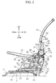
- Fig. 2 is a side view of the seat apparatus according to the embodiment of the present invention;
- Fig. 3 is a side view of a lifter device of the seat apparatus according to the embodiment of the present invention;
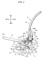
- Fig. 4 is a side view of the seat apparatus according to the embodiment of the present invention, specifically showing a tip-up device and a walk-in mechanism; and
- Fig. 5 is a perspective view of a reclining device of the seat apparatus according to the embodiment of the present invention.
- A
seat apparatus 1 according to an embodiment of the present invention will be described hereinafter with reference to Figs. 1 through 5. In these drawings, FR denotes "forward", RR denotes "rearward", UP denotes "upward" and LWR denotes "downward". These directions are defined for convenience of an explanation and any embodiments opposed to such a definition can be arbitrarily embodied. - The
seat apparatus 1 composes a basic framework of a seat for a vehicle and, as shown in Figs. 1 and 2, is generally provided with a pair ofslide devices 2, a pair of support frames 3, aseat cushion portion 4, aseatback portion 5, a recliningdevice 6, a tip-updevice 7, a lifter device 8 and a walk-inmechanism 9. Theseat apparatus 1 is combinedwith some elements such as aheadrest, a seat belt and a seat cover so as to form a seat for a vehicle, however, such elements are not shown in the drawings. Theslide devices 2 are combined with a body of the vehicle and then in use. - The
slide device 2 is provided withfixed rails 13 each having a slit on an upper side thereof, slidingrails 14, each of which is formed to have an inverted T-letter shape and slidably fitted into the slit, a slide-lock mechanism 15 for stopping the slidingrails 14 in a proper position andcoil springs 16 which are respectively stretched between thefixed rails 13 and the slidingrails 14 so as to give force to the slidingrails 14 in a forward direction. Furthermore, though not shown in the drawings, rollers and ball bearings for smoothly sliding the slidingrails 14 on the fixedrails 13 are further provided. Theslide devices 2 are provided at both sides of the seat in a symmetrical manner and fixed to a floor 10 (see Fig. 2) of a vehicle body byfirst brackets 11 respectively provided at a front thereof andsecond brackets 12 respectively provided at a rear thereof. - The support frames 3 are comprised of a pair of
frame bodies 21 made of steel sheets formed in a substantially right triangular shape and respectively provided withoval openings 22. The pairedframe bodies 21 are respectively fixed on the pair offixed rails 14 in a manner that a base of the right triangle is directed downward, a side orthogonal to the base is vertically directed and a remaining hypotenuse is directed forward. Theoval openings 22 are formed in an oval shape directed obliquely upward and forward so as to allow movement of athird shaft portion 27 described later. - As shown in Fig. 3, the lifter device 8 is provided with a first shaft portion 23, a
second shaft portion 24, which are projectingly provided on inner sides of the pairedframe bodies 21, agear 25 pivotally supported by the first shaft portion 23 and asector gear 26 pivotally supported by thesecond shaft portion 24. Thesector gear 26 has gear teeth 26a formed on the front side thereof, which engage with thegear 25 pivotally supported in front of thesector gear 26. Theoval openings 22 are formed so that the major axes thereof substantially correspond with an arc around thefirst shaft portion 24. Thegear 25 is capable of rotating by means of operation means 30. When lifting the operation means 30 upward, rotation of thegear 25 lets thesector gear 26 swing downward and afront end portion 31b of acushion frame 31 swing upward. When reversely operating the operation means 30, thefront end portion 31b swings downward. - As shown in Fig. 1, the
seat cushion portion 4 is provided with a closed-loop-like cushion frame 31,brackets 35 plurally formed on thecushion frame 31 and a plurality of S-shape springs 32 respectively stretched in an antero-posterior direction via theplural brackets 35. Theseat cushion portion 4 is covered with a pad and a cover, which are not shown in the drawings, so as to form a seat cushion. Arear end portion 31a of thecushion frame 31 is fixed to thethird shaft portion 27. Thecushion frame 31 is further provided withbrackets 34 and absorbers 33 made of any material having viscoelasticity such as rubber and laid on a peripheral surface of an upper side of thesecond shaft portion 24 with having thebrackets 34 and theabsorbers 33 therebetween. Theabsorbers 33 reduce noise whichmaybe generatedwhen thecushion frame 31 hits thesecond shaft portion 24. - The
second shaft portion 24 of thesector gear 26 is provided with afixed shaft 28 fixed to theframe bodies 21 androtation shafts 29 rotatably and pivotally supported by thefixed shaft 28. Thefixed shaft 28 and therotation shafts 29 are lubricated with a proper lubricant such as grease. Thefixed shaft 28 is provided with retaining means, such as conically expanded both ends thereof, so as to prevent therotation shafts 29 from displacement. - The
seatback portion 5 is provided with aseatback frame 41,sub-frames 42,upper end portions 42b of which are welded and fixed with rear sides oflower end portions 41a of theseatback frame 41, and a plurality ofwires 43 laid between both sides of theseatback frame 41. Theseatback portion 5 is covered with a pad and a cover, which are not shown in the drawings, so as to form a seatback. Thelower end portion 41a of theseatback frame 41 andlower end portion 42a of thesub-frame 42 is separated to have a space in an antero-posterior direction and the recliningdevice 6 falls within the space. Theseatback portion 5 is provided with a plurality ofholders 45 on an upper end thereof so as to support a headrest (not shown). - The reclining
device 6 is provided withcovers 51 for respectively covering thelower end portions 41a and thelower end portions 42a of thesub-frames 42,support members 52,base plates 53 supported on the upper end of theframe bodies 21,springs 54 for constantly pressing theseatback portion 5 forward and a device lever 55 for releasing a lock of the recliningdevice 6. When releasing the lock of the recliningdevice 6, theseatback portion 5 tilts forward by the pressing force of thesprings 54. Thelower end portions 41a of theseatback frame 41 are welded with front end portions of thecovers 51 and thelower end portions 42a of thesub-frames 42 are welded with rear end portions of thecovers 51, thereby theseatback frame 41 is fixed with thecovers 51. - As shown in Fig. 4, the tip-up
device 7 is provided withrestriction portions 61,arms 63 extended reward from thethird shaft portion 27 andfifth shaft portions 65 projectingly provided in front of thethird shaft portion 27. The tip-updevice 7 is fitted into thethird shaft portion 27 so as to be exterior to theframe bodies 21. Therestriction portion 61 is further provided with a through-hole 62 formed in a shape like an arc, which has a center on thethird shaft portion 27. Eacharm 63 is further provided with afourth shaft portion 64 projectingly provided on an outer surface thereof and thefourth shaft portion 64 is movably fitted in the through-hole 62. Between thefourth shaft portions 64 and thefifth shaft portions 65,coil springs 66 are respectively laid and stretched. Thefourth shaft portions 64 rotate around thethird shaft portion 27 and thesprings 66 are laid at thefifth shaft portions 65 disposed ahead of thethird shaft portion 27, thereby thesprings 66 give force to thefourth shaft portions 64 toward an upper end or a lower end of the through-hole 62. Therefore the vicinity of the center of the through-hole 62 is a dead point where the force by thesprings 66 is lost and unstable. - As shown in Figs. 2 and 4, the walk-in
mechanism 9 is provided with apedal lever 71, a slide-release link 74 cooperatively working with thepedal lever 71 and a slide-release plate 72. Thepedal lever 71 is extended from thethird shaft portion 27 of thecushion frame 31 to a lower side of theseat apparatus 1 and has apivot pin 71a at a middle thereof. The slide-release link 74 is formed in a substantially linear shape, a front end thereof is a fork end 74b having a cut 75 and arear end 74a is rotatably and pivotaly supported by thepivot pin 71a. The slide-release plate 72 is a flat plate having afirst wing 72a and asecond wing 72b and being formed in a boomerang-like shape. The slide-release plate 72 is rotatably and pivotally supported by theframe bodies 21 with asixth shaft portion 73. Apin 76 is projectingly formed on a tip end of thefirst wing 72a and slidably fitted to the cut 75. A proper clearance exists between a rear end 81 of the cut 75 and thepin 76. Slide-lock-release wires first wing 72a and thesecond wing 72b. A reclining-release wire 79 linking with thereclining device 6 is connected to a middle of thepedal lever 71. Aspring 80 constantly presses the slide-release plate 72 rearward. - Thewalk-
inmechanism 9 regulates operation of the slide-lock device 15, thereclining device 6 and the tip-updevice 7 in proportion to a shifting length of thepedal lever 71. When shifting thepedal lever 71 down, thecushion frame 31 swings upward around thethird shaft portion 27. When further shifting thepedal lever 71 down in an intermediate position thereof, thefourth shaft portions 64 swing upward over the dead point and is hence given downward force by thesprings 66, thereby thecushion frame 31 leaps up (tips up). Simultaneously, the rear end 74b of the slide-release link 74 is pressed downward and forward by thepedal lever 71, however, thepin 76 keeps still because the proper clearance exists between the rear end 81 and thepin 76. Meanwhile, when pressing thecushion frame 31 downward so that thefourth shaft portions 64 go over the dead point, thecushion frame 31 easily returns to its original position by means of the force by thesprings 66. - When shifting the
pedal lever 71 down in an end position thereof, the rear end 81 abuts and presses thepin 76 forward. Thereby the slide-release plate 72 swings around thesixth shaft portion 73 and the slide-release wires lock mechanism 15 is released. Provided that the slide-lock mechanism 15 is released, the slidingrails 14 move forward by means of the force by thespring 16. Simultaneously, the reclining-release wire 79 is pulled downward so that thereclining device 6 is released, thereby theseatback portion 5 can be tilted forward. - Namely, when shifting the
pedal lever 71 downward to a considerable extent, tipping-up of theseat cushion portion 4, tilting of theseatback portion 5 and moving forward of the slidingrails 14 are simultaneously achieved. Moreover, the tipping-up of theseat cushion portion 4 makes it possible to slide whole of the seat forward in a large distance. - Although the invention has been described above by reference to certain embodiments of the invention, the invention is not limited to the embodiments described above. Modifications and variations of the embodiments described above will occur to those skilled in the art, in light of the above teachings.
- A seat for a vehicle, in which a shift of the lever alone enables tipping-up the seat cushion, reclining the seatback and sliding the seat, is provided. The seat can be slid in a large distance because the seat cushion moves accompanying with tipping-up thereof. Such a movement as well as reclining the seatback make it easy for an occupant to move within the vehicle.
Claims (3)
- A seat for a vehicle comprising:a sliding device including a slide-lock mechanism, the sliding device sliding a seat body in a case of releasing the slide-lock mechanism;a seatback including a reclining device, the seatback being tilted forward in a case of releasing the reclining device;a seat cushion including a tip-up device, the seat cushion being tipped up in a case of operating the tip-up device; anda walk-in mechanism including a lever, the walk-in mechanism configured to release the slide-lock mechanism, release the reclining device and operate the tip-up device in proportion to a shifting length of the lever.
- The seat set forth in claim 1, wherein the walk-in mechanism is configured to operate the tip-up device in a case of shifting the lever in an intermediate position thereof, to release the slide-lock mechanism and the reclining device in a case of shifting the lever in an end position thereof.
- The seat set forth in claim 1 or 2, wherein the walk-in mechanism comprises;
a slide-release link pivotally supported by the lever; and
a slide-release plate including a slide-release wire connected to the slide-lock mechanism, a reclining-release wire connected to the reclining device and a pin leaving a clearance to the slide-release link,
the lever being connected to the tip-up device so configured as to operate the tip-up device in a case of shifting the lever in an intermediate position thereof,
the lever being configured to clear the clearance so that the pin presses the slide-release link whereby the slide-release plate swings and the slide-release wire and the reclining-release wire are pulled so as to release the slide-lock mechanism and the reclining device in a case of shifting the lever in an end position thereof.
Applications Claiming Priority (3)
| Application Number | Priority Date | Filing Date | Title |
|---|---|---|---|
| JP2002094619A JP2003285674A (en) | 2002-03-29 | 2002-03-29 | Seat for vehicle |
| JP2002094619 | 2002-03-29 | ||
| PCT/JP2003/003726 WO2003082624A1 (en) | 2002-03-29 | 2003-03-26 | Vehicle seat |
Publications (3)
| Publication Number | Publication Date |
|---|---|
| EP1491389A1 true EP1491389A1 (en) | 2004-12-29 |
| EP1491389A4 EP1491389A4 (en) | 2009-08-05 |
| EP1491389B1 EP1491389B1 (en) | 2010-09-08 |
Family
ID=28671791
Family Applications (1)
| Application Number | Title | Priority Date | Filing Date |
|---|---|---|---|
| EP03745421A Expired - Lifetime EP1491389B1 (en) | 2002-03-29 | 2003-03-26 | Vehicle seat |
Country Status (7)
| Country | Link |
|---|---|
| US (1) | US7350867B2 (en) |
| EP (1) | EP1491389B1 (en) |
| JP (1) | JP2003285674A (en) |
| CN (1) | CN100460242C (en) |
| AU (1) | AU2003236148A1 (en) |
| DE (1) | DE60334085D1 (en) |
| WO (1) | WO2003082624A1 (en) |
Cited By (3)
| Publication number | Priority date | Publication date | Assignee | Title |
|---|---|---|---|---|
| GB2423014A (en) * | 2005-02-11 | 2006-08-16 | Lear Corp | Vehicle seat recliner with dampener |
| CN102343837A (en) * | 2010-07-22 | 2012-02-08 | 丰田纺织株式会社 | Vehicle seat |
| FR3053641A1 (en) * | 2016-07-05 | 2018-01-12 | Renault Sas | SEAT STRUCTURE WITH FOLDING MECHANISM FOR MOTOR VEHICLE |
Families Citing this family (22)
| Publication number | Priority date | Publication date | Assignee | Title |
|---|---|---|---|---|
| JP4064331B2 (en) * | 2003-10-14 | 2008-03-19 | 本田技研工業株式会社 | Seat adjuster device |
| WO2006030539A1 (en) * | 2004-09-17 | 2006-03-23 | Aisin Seiki Kabushiki Kaisha | Walk-in device |
| JP4104601B2 (en) | 2005-02-14 | 2008-06-18 | トヨタ車体株式会社 | Vehicle seat |
| DE102006033554A1 (en) * | 2005-08-24 | 2007-03-01 | C. Rob. Hammerstein Gmbh & Co. Kg | Foldable seat for motor vehicle, has swivelable backrest formed with projection, which comes to stop at rear side of control area in support part upon forward tilting of backrest, where backrest is tilted together with swiveling of part |
| JP5141680B2 (en) * | 2007-02-23 | 2013-02-13 | トヨタ紡織株式会社 | Vehicle seat |
| DE102010051337B4 (en) * | 2010-11-13 | 2014-11-20 | Faurecia Autositze Gmbh | Manually longitudinally adjustable motor vehicle seat |
| KR101210155B1 (en) * | 2010-12-07 | 2012-12-07 | 기아자동차주식회사 | Back reclining device interconnected with cushion of seat for vehicle |
| US8869731B2 (en) * | 2012-03-16 | 2014-10-28 | Hobie Cat Company | Adjustable kayak chair |
| US9114732B2 (en) * | 2012-06-01 | 2015-08-25 | Faurecia Automotive Seating, Llc | Easy-entry vehicle seat |
| KR20150027742A (en) | 2012-06-01 | 2015-03-12 | 마그나 시팅 인크. | Fold and kneel seat with rearward folding motion |
| US8882197B2 (en) * | 2012-08-28 | 2014-11-11 | Ford Global Technologies, Llc | Ultra flex and fold seat with ingress/egress feature |
| US9283873B2 (en) | 2012-12-17 | 2016-03-15 | Ford Global Technologies, Llc | Flex and fold vehicle seating assembly |
| JP6040817B2 (en) * | 2013-03-21 | 2016-12-07 | トヨタ紡織株式会社 | Vehicle seat |
| US9643519B2 (en) | 2013-04-12 | 2017-05-09 | Honda Motor Co., Ltd. | Vehicular seat device |
| US9187179B1 (en) * | 2014-05-20 | 2015-11-17 | Goodrich Corporation | Seat pan closure mechanism |
| US9527555B2 (en) | 2014-07-24 | 2016-12-27 | Hobie Cat Company | Adjustable kayak chair IM |
| CN104986084A (en) * | 2015-06-29 | 2015-10-21 | 苏州中航中振汽车饰件有限公司 | Three-person seat with leg holders |
| US10065536B2 (en) * | 2015-09-24 | 2018-09-04 | Fca Us Llc | Reclining seat for a vehicle |
| US10308146B1 (en) * | 2018-01-25 | 2019-06-04 | Ford Global Technologies, Llc | Track release mechanism for a seating assembly |
| US10232740B1 (en) * | 2018-03-06 | 2019-03-19 | Ford Global Technologies, Llc | Adjustable seatback recline angle and warning system |
| JP2024092595A (en) * | 2022-12-26 | 2024-07-08 | トヨタ自動車株式会社 | Vehicle seat |
| US20260097691A1 (en) * | 2024-10-09 | 2026-04-09 | Ford Global Technologies, Llc | Vehicle seat assembly having cushion tube with support brackets |
Family Cites Families (39)
| Publication number | Priority date | Publication date | Assignee | Title |
|---|---|---|---|---|
| JPS5047319A (en) * | 1973-08-31 | 1975-04-26 | ||
| GB1446992A (en) * | 1974-03-07 | 1976-08-18 | Chrysler Uk | Vehicle seat assemblies |
| JPS52105428A (en) * | 1976-02-27 | 1977-09-03 | Nissan Motor Co Ltd | Memory including seat for walk-in rail |
| US4065178A (en) * | 1977-03-18 | 1977-12-27 | General Motors Corporation | Easy enter seat assembly |
| JPS58105711A (en) * | 1981-12-19 | 1983-06-23 | 日産自動車株式会社 | Seat for automobile |
| JPS59163532A (en) | 1983-03-09 | 1984-09-14 | Hokkai Can Co Ltd | Method and device for inspecting internal pressure of tightly sealed-up vessel |
| JPS59163532U (en) * | 1983-04-19 | 1984-11-01 | トヨタ自動車株式会社 | Rotating walk-in mechanism |
| US4607884A (en) * | 1984-08-06 | 1986-08-26 | Chrysler Corporation | Vehicle easy entry seat latching mechanism |
| JPS6137849U (en) * | 1984-08-10 | 1986-03-08 | シロキ工業株式会社 | reclining device |
| JPS61205524A (en) | 1985-03-08 | 1986-09-11 | Nissan Motor Co Ltd | Walk-in device for car seat |
| US4652052A (en) * | 1985-04-24 | 1987-03-24 | Magna International Inc. | Memory seat assembly |
| CA1246430A (en) * | 1985-06-18 | 1988-12-13 | Dukecal J. Harding | Seat assembly |
| JPS6328743A (en) * | 1986-07-23 | 1988-02-06 | Oi Seisakusho Co Ltd | Seat slide device for automobile |
| JPS63161040A (en) | 1986-12-25 | 1988-07-04 | Yokohama Rubber Co Ltd:The | Antifouling rubber composition |
| JPH0619392Y2 (en) * | 1987-04-13 | 1994-05-25 | アラコ株式会社 | Seat slide device for walk-in seat |
| US4852846A (en) * | 1987-09-04 | 1989-08-01 | General Motors Corporation | Method and apparatus of a conventional fore and aft vehicle seat adjuster convertible into an easy entry seat adjuster slide |
| JPH0431143Y2 (en) * | 1987-09-30 | 1992-07-27 | ||
| US4844542A (en) * | 1988-08-29 | 1989-07-04 | General Motors Corporation | Easy entry seat adjuster with memory |
| US4881774A (en) * | 1988-11-07 | 1989-11-21 | Bertrand Faure Automobile | Memory seat track assembly for vehicle seat |
| GB8917633D0 (en) * | 1989-08-02 | 1989-09-20 | Ti Cox Ltd | Improvements in vehicle seat slide mechanisms |
| US5137331A (en) * | 1990-11-30 | 1992-08-11 | Magna International Inc. | Seat track assembly with mechanical memory |
| US5390980A (en) * | 1993-02-10 | 1995-02-21 | Bertrand Faure Ltd. | Zero chuck vehicle seat latching mechanism |
| JPH0713241U (en) | 1993-08-18 | 1995-03-07 | アラコ株式会社 | Mounting structure for operating cables in vehicle seats |
| DE19510618A1 (en) * | 1994-05-19 | 1995-11-23 | Hammerstein Gmbh C Rob | Vehicle seat, which can be moved longitudinally if backrest is folded |
| US5597206A (en) * | 1995-10-31 | 1997-01-28 | Douglas & Lomason Company | Easy entry seat adjuster |
| JP3385144B2 (en) | 1995-12-30 | 2003-03-10 | 株式会社タチエス | Jumping seat lock device |
| FR2746354B1 (en) * | 1996-03-25 | 1998-05-22 | Faure Bertrand Equipements Sa | SLIDE FOR VEHICLE SEAT, AND SEAT COMPRISING SUCH A SLIDE |
| BR9713997A (en) * | 1996-12-09 | 2000-02-29 | Atoma Int Inc | Vehicle seat |
| US5899532A (en) * | 1997-10-06 | 1999-05-04 | Excel Industries, Inc. | Easy entry seat track assembly with single point memory |
| US5944383A (en) * | 1997-10-17 | 1999-08-31 | Dura Automotive Systems, Inc. | Easy entry seat track assembly with full memory |
| JP3813745B2 (en) | 1998-09-25 | 2006-08-23 | シロキ工業株式会社 | Sheet storage device |
| EP1126992B2 (en) * | 1998-11-03 | 2007-02-21 | Magna Seating Systems Inc. | Easy access seat assembly with full memory |
| CN1128728C (en) * | 1998-11-05 | 2003-11-26 | 麦格纳座椅系统公司 | Easy entry mid-position memory seat |
| DE19962424C1 (en) * | 1999-12-22 | 2001-08-23 | Faurecia Autositze Gmbh & Co | Motor vehicle seat with a linkage for translational transmission of adjustment forces for seat adjustment functions |
| EP1309466B1 (en) * | 2000-08-14 | 2004-10-20 | Intier Automotive Inc. | Easy entry seat adjuster with mid position memory |
| US6443414B1 (en) * | 2000-10-18 | 2002-09-03 | Dura Global Technologies | Seat track assembly with release mechanism having a rotatable rod |
| DE10151762B4 (en) * | 2001-10-19 | 2007-08-16 | C. Rob. Hammerstein Gmbh & Co. Kg | Predisplaceable motor vehicle seat with access to a rear seat through a front door |
| JP3833936B2 (en) * | 2001-12-25 | 2006-10-18 | アイシン精機株式会社 | Sheet device |
| US6767063B1 (en) * | 2003-01-20 | 2004-07-27 | Lear Corporation | Automotive easy-entry assembly |
-
2002
- 2002-03-29 JP JP2002094619A patent/JP2003285674A/en active Pending
-
2003
- 2003-03-26 EP EP03745421A patent/EP1491389B1/en not_active Expired - Lifetime
- 2003-03-26 WO PCT/JP2003/003726 patent/WO2003082624A1/en not_active Ceased
- 2003-03-26 US US10/509,566 patent/US7350867B2/en not_active Expired - Fee Related
- 2003-03-26 CN CNB03807446XA patent/CN100460242C/en not_active Expired - Fee Related
- 2003-03-26 DE DE60334085T patent/DE60334085D1/en not_active Expired - Lifetime
- 2003-03-26 AU AU2003236148A patent/AU2003236148A1/en not_active Abandoned
Cited By (5)
| Publication number | Priority date | Publication date | Assignee | Title |
|---|---|---|---|---|
| GB2423014A (en) * | 2005-02-11 | 2006-08-16 | Lear Corp | Vehicle seat recliner with dampener |
| US7344195B2 (en) | 2005-02-11 | 2008-03-18 | Lear Corporation | Dampener for a vehicle seat recliner |
| GB2423014B (en) * | 2005-02-11 | 2008-04-16 | Lear Corp | Dampener For A Vehicle Seat Recliner |
| CN102343837A (en) * | 2010-07-22 | 2012-02-08 | 丰田纺织株式会社 | Vehicle seat |
| FR3053641A1 (en) * | 2016-07-05 | 2018-01-12 | Renault Sas | SEAT STRUCTURE WITH FOLDING MECHANISM FOR MOTOR VEHICLE |
Also Published As
| Publication number | Publication date |
|---|---|
| WO2003082624A1 (en) | 2003-10-09 |
| US7350867B2 (en) | 2008-04-01 |
| CN100460242C (en) | 2009-02-11 |
| US20060071527A1 (en) | 2006-04-06 |
| CN1642774A (en) | 2005-07-20 |
| AU2003236148A1 (en) | 2003-10-13 |
| EP1491389A4 (en) | 2009-08-05 |
| DE60334085D1 (en) | 2010-10-21 |
| JP2003285674A (en) | 2003-10-07 |
| EP1491389B1 (en) | 2010-09-08 |
| WO2003082624A8 (en) | 2005-03-10 |
Similar Documents
| Publication | Publication Date | Title |
|---|---|---|
| EP1491389B1 (en) | Vehicle seat | |
| JP3878099B2 (en) | Vehicle seat arrangement structure | |
| EP1491390A1 (en) | Seat for vehicle | |
| JPH10100747A (en) | Vehicle seat structure | |
| JPH10138811A (en) | Vehicle headrest device | |
| JP3173700B2 (en) | Vehicle seat | |
| JP5381092B2 (en) | Vehicle seat device | |
| JP5609601B2 (en) | Ottoman equipment | |
| JP2024013134A (en) | Headrests and vehicle seats | |
| JP5578054B2 (en) | Ottoman equipment | |
| JP3771204B2 (en) | Vehicle seat structure | |
| JP2000085424A (en) | Vehicle seat | |
| CN222372737U (en) | Seat skeleton, seat and equipment | |
| ATE287348T1 (en) | FOLDABLE REAR SEAT FOR MOTOR VEHICLES | |
| JP3771251B2 (en) | Vehicle seat structure | |
| JP4095008B2 (en) | Vehicle seat | |
| JP2010088814A (en) | Chair with reclining mechanism | |
| JP2009035022A (en) | Vehicle seat device | |
| JP2026047563A (en) | Table device for seats | |
| JP2007331400A (en) | Vehicle seat device | |
| JP2008073214A (en) | Sheet device | |
| JP2004330915A (en) | Sheet structure of vehicle | |
| JP2009262696A (en) | Structure of jumping-up type vehicular seat | |
| JP2003289971A (en) | Seat for vehicle | |
| JPS6211234Y2 (en) |
Legal Events
| Date | Code | Title | Description |
|---|---|---|---|
| PUAI | Public reference made under article 153(3) epc to a published international application that has entered the european phase |
Free format text: ORIGINAL CODE: 0009012 |
|
| 17P | Request for examination filed |
Effective date: 20041008 |
|
| AK | Designated contracting states |
Kind code of ref document: A1 Designated state(s): DE FR GB |
|
| AX | Request for extension of the european patent |
Extension state: AL LT LV MK |
|
| A4 | Supplementary search report drawn up and despatched |
Effective date: 20090703 |
|
| RIC1 | Information provided on ipc code assigned before grant |
Ipc: B60N 2/12 20060101AFI20031016BHEP Ipc: B60N 2/30 20060101ALI20090629BHEP Ipc: B60N 2/20 20060101ALI20090629BHEP Ipc: B60N 2/08 20060101ALI20090629BHEP |
|
| GRAP | Despatch of communication of intention to grant a patent |
Free format text: ORIGINAL CODE: EPIDOSNIGR1 |
|
| GRAS | Grant fee paid |
Free format text: ORIGINAL CODE: EPIDOSNIGR3 |
|
| GRAA | (expected) grant |
Free format text: ORIGINAL CODE: 0009210 |
|
| AK | Designated contracting states |
Kind code of ref document: B1 Designated state(s): DE FR GB |
|
| REG | Reference to a national code |
Ref country code: GB Ref legal event code: FG4D |
|
| REF | Corresponds to: |
Ref document number: 60334085 Country of ref document: DE Date of ref document: 20101021 Kind code of ref document: P |
|
| PLBE | No opposition filed within time limit |
Free format text: ORIGINAL CODE: 0009261 |
|
| STAA | Information on the status of an ep patent application or granted ep patent |
Free format text: STATUS: NO OPPOSITION FILED WITHIN TIME LIMIT |
|
| 26N | No opposition filed |
Effective date: 20110609 |
|
| REG | Reference to a national code |
Ref country code: DE Ref legal event code: R097 Ref document number: 60334085 Country of ref document: DE Effective date: 20110609 |
|
| REG | Reference to a national code |
Ref country code: FR Ref legal event code: PLFP Year of fee payment: 14 |
|
| PGFP | Annual fee paid to national office [announced via postgrant information from national office to epo] |
Ref country code: GB Payment date: 20160321 Year of fee payment: 14 Ref country code: FR Payment date: 20160321 Year of fee payment: 14 |
|
| PGFP | Annual fee paid to national office [announced via postgrant information from national office to epo] |
Ref country code: DE Payment date: 20160330 Year of fee payment: 14 |
|
| REG | Reference to a national code |
Ref country code: DE Ref legal event code: R119 Ref document number: 60334085 Country of ref document: DE |
|
| GBPC | Gb: european patent ceased through non-payment of renewal fee |
Effective date: 20170326 |
|
| REG | Reference to a national code |
Ref country code: FR Ref legal event code: ST Effective date: 20171130 |
|
| PG25 | Lapsed in a contracting state [announced via postgrant information from national office to epo] |
Ref country code: FR Free format text: LAPSE BECAUSE OF NON-PAYMENT OF DUE FEES Effective date: 20170331 Ref country code: DE Free format text: LAPSE BECAUSE OF NON-PAYMENT OF DUE FEES Effective date: 20171003 |
|
| PG25 | Lapsed in a contracting state [announced via postgrant information from national office to epo] |
Ref country code: GB Free format text: LAPSE BECAUSE OF NON-PAYMENT OF DUE FEES Effective date: 20170326 |