EP1491386A1 - Braking system of hybrid vehicle - Google Patents
Braking system of hybrid vehicle Download PDFInfo
- Publication number
- EP1491386A1 EP1491386A1 EP03708671A EP03708671A EP1491386A1 EP 1491386 A1 EP1491386 A1 EP 1491386A1 EP 03708671 A EP03708671 A EP 03708671A EP 03708671 A EP03708671 A EP 03708671A EP 1491386 A1 EP1491386 A1 EP 1491386A1
- Authority
- EP
- European Patent Office
- Prior art keywords
- braking
- motor
- vehicle
- braking force
- engine
- Prior art date
- Legal status (The legal status is an assumption and is not a legal conclusion. Google has not performed a legal analysis and makes no representation as to the accuracy of the status listed.)
- Granted
Links
Images


Classifications
-
- B—PERFORMING OPERATIONS; TRANSPORTING
- B60—VEHICLES IN GENERAL
- B60W—CONJOINT CONTROL OF VEHICLE SUB-UNITS OF DIFFERENT TYPE OR DIFFERENT FUNCTION; CONTROL SYSTEMS SPECIALLY ADAPTED FOR HYBRID VEHICLES; ROAD VEHICLE DRIVE CONTROL SYSTEMS FOR PURPOSES NOT RELATED TO THE CONTROL OF A PARTICULAR SUB-UNIT
- B60W20/00—Control systems specially adapted for hybrid vehicles
- B60W20/10—Controlling the power contribution of each of the prime movers to meet required power demand
- B60W20/13—Controlling the power contribution of each of the prime movers to meet required power demand in order to stay within battery power input or output limits; in order to prevent overcharging or battery depletion
-
- B—PERFORMING OPERATIONS; TRANSPORTING
- B60—VEHICLES IN GENERAL
- B60K—ARRANGEMENT OR MOUNTING OF PROPULSION UNITS OR OF TRANSMISSIONS IN VEHICLES; ARRANGEMENT OR MOUNTING OF PLURAL DIVERSE PRIME-MOVERS IN VEHICLES; AUXILIARY DRIVES FOR VEHICLES; INSTRUMENTATION OR DASHBOARDS FOR VEHICLES; ARRANGEMENTS IN CONNECTION WITH COOLING, AIR INTAKE, GAS EXHAUST OR FUEL SUPPLY OF PROPULSION UNITS IN VEHICLES
- B60K6/00—Arrangement or mounting of plural diverse prime-movers for mutual or common propulsion, e.g. hybrid propulsion systems comprising electric motors and internal combustion engines ; Control systems therefor, i.e. systems controlling two or more prime movers, or controlling one of these prime movers and any of the transmission, drive or drive units Informative references: mechanical gearings with secondary electric drive F16H3/72; arrangements for handling mechanical energy structurally associated with the dynamo-electric machine H02K7/00; machines comprising structurally interrelated motor and generator parts H02K51/00; dynamo-electric machines not otherwise provided for in H02K see H02K99/00
- B60K6/20—Arrangement or mounting of plural diverse prime-movers for mutual or common propulsion, e.g. hybrid propulsion systems comprising electric motors and internal combustion engines ; Control systems therefor, i.e. systems controlling two or more prime movers, or controlling one of these prime movers and any of the transmission, drive or drive units Informative references: mechanical gearings with secondary electric drive F16H3/72; arrangements for handling mechanical energy structurally associated with the dynamo-electric machine H02K7/00; machines comprising structurally interrelated motor and generator parts H02K51/00; dynamo-electric machines not otherwise provided for in H02K see H02K99/00 the prime-movers consisting of electric motors and internal combustion engines, e.g. HEVs
- B60K6/42—Arrangement or mounting of plural diverse prime-movers for mutual or common propulsion, e.g. hybrid propulsion systems comprising electric motors and internal combustion engines ; Control systems therefor, i.e. systems controlling two or more prime movers, or controlling one of these prime movers and any of the transmission, drive or drive units Informative references: mechanical gearings with secondary electric drive F16H3/72; arrangements for handling mechanical energy structurally associated with the dynamo-electric machine H02K7/00; machines comprising structurally interrelated motor and generator parts H02K51/00; dynamo-electric machines not otherwise provided for in H02K see H02K99/00 the prime-movers consisting of electric motors and internal combustion engines, e.g. HEVs characterised by the architecture of the hybrid electric vehicle
- B60K6/44—Series-parallel type
-
- B—PERFORMING OPERATIONS; TRANSPORTING
- B60—VEHICLES IN GENERAL
- B60K—ARRANGEMENT OR MOUNTING OF PROPULSION UNITS OR OF TRANSMISSIONS IN VEHICLES; ARRANGEMENT OR MOUNTING OF PLURAL DIVERSE PRIME-MOVERS IN VEHICLES; AUXILIARY DRIVES FOR VEHICLES; INSTRUMENTATION OR DASHBOARDS FOR VEHICLES; ARRANGEMENTS IN CONNECTION WITH COOLING, AIR INTAKE, GAS EXHAUST OR FUEL SUPPLY OF PROPULSION UNITS IN VEHICLES
- B60K6/00—Arrangement or mounting of plural diverse prime-movers for mutual or common propulsion, e.g. hybrid propulsion systems comprising electric motors and internal combustion engines ; Control systems therefor, i.e. systems controlling two or more prime movers, or controlling one of these prime movers and any of the transmission, drive or drive units Informative references: mechanical gearings with secondary electric drive F16H3/72; arrangements for handling mechanical energy structurally associated with the dynamo-electric machine H02K7/00; machines comprising structurally interrelated motor and generator parts H02K51/00; dynamo-electric machines not otherwise provided for in H02K see H02K99/00
- B60K6/20—Arrangement or mounting of plural diverse prime-movers for mutual or common propulsion, e.g. hybrid propulsion systems comprising electric motors and internal combustion engines ; Control systems therefor, i.e. systems controlling two or more prime movers, or controlling one of these prime movers and any of the transmission, drive or drive units Informative references: mechanical gearings with secondary electric drive F16H3/72; arrangements for handling mechanical energy structurally associated with the dynamo-electric machine H02K7/00; machines comprising structurally interrelated motor and generator parts H02K51/00; dynamo-electric machines not otherwise provided for in H02K see H02K99/00 the prime-movers consisting of electric motors and internal combustion engines, e.g. HEVs
- B60K6/42—Arrangement or mounting of plural diverse prime-movers for mutual or common propulsion, e.g. hybrid propulsion systems comprising electric motors and internal combustion engines ; Control systems therefor, i.e. systems controlling two or more prime movers, or controlling one of these prime movers and any of the transmission, drive or drive units Informative references: mechanical gearings with secondary electric drive F16H3/72; arrangements for handling mechanical energy structurally associated with the dynamo-electric machine H02K7/00; machines comprising structurally interrelated motor and generator parts H02K51/00; dynamo-electric machines not otherwise provided for in H02K see H02K99/00 the prime-movers consisting of electric motors and internal combustion engines, e.g. HEVs characterised by the architecture of the hybrid electric vehicle
- B60K6/48—Parallel type
-
- B—PERFORMING OPERATIONS; TRANSPORTING
- B60—VEHICLES IN GENERAL
- B60K—ARRANGEMENT OR MOUNTING OF PROPULSION UNITS OR OF TRANSMISSIONS IN VEHICLES; ARRANGEMENT OR MOUNTING OF PLURAL DIVERSE PRIME-MOVERS IN VEHICLES; AUXILIARY DRIVES FOR VEHICLES; INSTRUMENTATION OR DASHBOARDS FOR VEHICLES; ARRANGEMENTS IN CONNECTION WITH COOLING, AIR INTAKE, GAS EXHAUST OR FUEL SUPPLY OF PROPULSION UNITS IN VEHICLES
- B60K6/00—Arrangement or mounting of plural diverse prime-movers for mutual or common propulsion, e.g. hybrid propulsion systems comprising electric motors and internal combustion engines ; Control systems therefor, i.e. systems controlling two or more prime movers, or controlling one of these prime movers and any of the transmission, drive or drive units Informative references: mechanical gearings with secondary electric drive F16H3/72; arrangements for handling mechanical energy structurally associated with the dynamo-electric machine H02K7/00; machines comprising structurally interrelated motor and generator parts H02K51/00; dynamo-electric machines not otherwise provided for in H02K see H02K99/00
- B60K6/20—Arrangement or mounting of plural diverse prime-movers for mutual or common propulsion, e.g. hybrid propulsion systems comprising electric motors and internal combustion engines ; Control systems therefor, i.e. systems controlling two or more prime movers, or controlling one of these prime movers and any of the transmission, drive or drive units Informative references: mechanical gearings with secondary electric drive F16H3/72; arrangements for handling mechanical energy structurally associated with the dynamo-electric machine H02K7/00; machines comprising structurally interrelated motor and generator parts H02K51/00; dynamo-electric machines not otherwise provided for in H02K see H02K99/00 the prime-movers consisting of electric motors and internal combustion engines, e.g. HEVs
- B60K6/50—Architecture of the driveline characterised by arrangement or kind of transmission units
- B60K6/52—Driving a plurality of drive axles, e.g. four-wheel drive
-
- B—PERFORMING OPERATIONS; TRANSPORTING
- B60—VEHICLES IN GENERAL
- B60L—PROPULSION OF ELECTRICALLY-PROPELLED VEHICLES; SUPPLYING ELECTRIC POWER FOR AUXILIARY EQUIPMENT OF ELECTRICALLY-PROPELLED VEHICLES; ELECTRODYNAMIC BRAKE SYSTEMS FOR VEHICLES IN GENERAL; MAGNETIC SUSPENSION OR LEVITATION FOR VEHICLES; MONITORING OPERATING VARIABLES OF ELECTRICALLY-PROPELLED VEHICLES; ELECTRIC SAFETY DEVICES FOR ELECTRICALLY-PROPELLED VEHICLES
- B60L7/00—Electrodynamic brake systems for vehicles in general
- B60L7/24—Electrodynamic brake systems for vehicles in general with additional mechanical or electromagnetic braking
-
- B—PERFORMING OPERATIONS; TRANSPORTING
- B60—VEHICLES IN GENERAL
- B60T—VEHICLE BRAKE CONTROL SYSTEMS OR PARTS THEREOF; BRAKE CONTROL SYSTEMS OR PARTS THEREOF, IN GENERAL; ARRANGEMENT OF BRAKING ELEMENTS ON VEHICLES IN GENERAL; PORTABLE DEVICES FOR PREVENTING UNWANTED MOVEMENT OF VEHICLES; VEHICLE MODIFICATIONS TO FACILITATE COOLING OF BRAKES
- B60T1/00—Arrangements of braking elements, i.e. of those parts where braking effect occurs specially for vehicles
- B60T1/02—Arrangements of braking elements, i.e. of those parts where braking effect occurs specially for vehicles acting by retarding wheels
- B60T1/10—Arrangements of braking elements, i.e. of those parts where braking effect occurs specially for vehicles acting by retarding wheels by utilising wheel movement for accumulating energy, e.g. driving air compressors
-
- B—PERFORMING OPERATIONS; TRANSPORTING
- B60—VEHICLES IN GENERAL
- B60T—VEHICLE BRAKE CONTROL SYSTEMS OR PARTS THEREOF; BRAKE CONTROL SYSTEMS OR PARTS THEREOF, IN GENERAL; ARRANGEMENT OF BRAKING ELEMENTS ON VEHICLES IN GENERAL; PORTABLE DEVICES FOR PREVENTING UNWANTED MOVEMENT OF VEHICLES; VEHICLE MODIFICATIONS TO FACILITATE COOLING OF BRAKES
- B60T13/00—Transmitting braking action from initiating means to ultimate brake actuator with power assistance or drive; Brake systems incorporating such transmitting means, e.g. air-pressure brake systems
- B60T13/74—Transmitting braking action from initiating means to ultimate brake actuator with power assistance or drive; Brake systems incorporating such transmitting means, e.g. air-pressure brake systems with electrical assistance or drive
-
- B—PERFORMING OPERATIONS; TRANSPORTING
- B60—VEHICLES IN GENERAL
- B60T—VEHICLE BRAKE CONTROL SYSTEMS OR PARTS THEREOF; BRAKE CONTROL SYSTEMS OR PARTS THEREOF, IN GENERAL; ARRANGEMENT OF BRAKING ELEMENTS ON VEHICLES IN GENERAL; PORTABLE DEVICES FOR PREVENTING UNWANTED MOVEMENT OF VEHICLES; VEHICLE MODIFICATIONS TO FACILITATE COOLING OF BRAKES
- B60T17/00—Component parts, details, or accessories of power brake systems not covered by groups B60T8/00, B60T13/00 or B60T15/00, or presenting other characteristic features
- B60T17/04—Arrangements of piping, valves in the piping, e.g. cut-off valves, couplings or air hoses
- B60T17/043—Brake line couplings, air hoses and stopcocks
-
- B—PERFORMING OPERATIONS; TRANSPORTING
- B60—VEHICLES IN GENERAL
- B60T—VEHICLE BRAKE CONTROL SYSTEMS OR PARTS THEREOF; BRAKE CONTROL SYSTEMS OR PARTS THEREOF, IN GENERAL; ARRANGEMENT OF BRAKING ELEMENTS ON VEHICLES IN GENERAL; PORTABLE DEVICES FOR PREVENTING UNWANTED MOVEMENT OF VEHICLES; VEHICLE MODIFICATIONS TO FACILITATE COOLING OF BRAKES
- B60T17/00—Component parts, details, or accessories of power brake systems not covered by groups B60T8/00, B60T13/00 or B60T15/00, or presenting other characteristic features
- B60T17/18—Safety devices; Monitoring
- B60T17/22—Devices for monitoring or checking brake systems; Signal devices
-
- B—PERFORMING OPERATIONS; TRANSPORTING
- B60—VEHICLES IN GENERAL
- B60T—VEHICLE BRAKE CONTROL SYSTEMS OR PARTS THEREOF; BRAKE CONTROL SYSTEMS OR PARTS THEREOF, IN GENERAL; ARRANGEMENT OF BRAKING ELEMENTS ON VEHICLES IN GENERAL; PORTABLE DEVICES FOR PREVENTING UNWANTED MOVEMENT OF VEHICLES; VEHICLE MODIFICATIONS TO FACILITATE COOLING OF BRAKES
- B60T8/00—Arrangements for adjusting wheel-braking force to meet varying vehicular or ground-surface conditions, e.g. limiting or varying distribution of braking force
- B60T8/26—Arrangements for adjusting wheel-braking force to meet varying vehicular or ground-surface conditions, e.g. limiting or varying distribution of braking force characterised by producing differential braking between front and rear wheels
- B60T8/266—Arrangements for adjusting wheel-braking force to meet varying vehicular or ground-surface conditions, e.g. limiting or varying distribution of braking force characterised by producing differential braking between front and rear wheels using valves or actuators with external control means
- B60T8/267—Arrangements for adjusting wheel-braking force to meet varying vehicular or ground-surface conditions, e.g. limiting or varying distribution of braking force characterised by producing differential braking between front and rear wheels using valves or actuators with external control means for hybrid systems with different kind of brakes on different axles
-
- B—PERFORMING OPERATIONS; TRANSPORTING
- B60—VEHICLES IN GENERAL
- B60W—CONJOINT CONTROL OF VEHICLE SUB-UNITS OF DIFFERENT TYPE OR DIFFERENT FUNCTION; CONTROL SYSTEMS SPECIALLY ADAPTED FOR HYBRID VEHICLES; ROAD VEHICLE DRIVE CONTROL SYSTEMS FOR PURPOSES NOT RELATED TO THE CONTROL OF A PARTICULAR SUB-UNIT
- B60W10/00—Conjoint control of vehicle sub-units of different type or different function
- B60W10/04—Conjoint control of vehicle sub-units of different type or different function including control of propulsion units
- B60W10/06—Conjoint control of vehicle sub-units of different type or different function including control of propulsion units including control of combustion engines
-
- B—PERFORMING OPERATIONS; TRANSPORTING
- B60—VEHICLES IN GENERAL
- B60W—CONJOINT CONTROL OF VEHICLE SUB-UNITS OF DIFFERENT TYPE OR DIFFERENT FUNCTION; CONTROL SYSTEMS SPECIALLY ADAPTED FOR HYBRID VEHICLES; ROAD VEHICLE DRIVE CONTROL SYSTEMS FOR PURPOSES NOT RELATED TO THE CONTROL OF A PARTICULAR SUB-UNIT
- B60W10/00—Conjoint control of vehicle sub-units of different type or different function
- B60W10/04—Conjoint control of vehicle sub-units of different type or different function including control of propulsion units
- B60W10/08—Conjoint control of vehicle sub-units of different type or different function including control of propulsion units including control of electric propulsion units, e.g. motors or generators
-
- B—PERFORMING OPERATIONS; TRANSPORTING
- B60—VEHICLES IN GENERAL
- B60W—CONJOINT CONTROL OF VEHICLE SUB-UNITS OF DIFFERENT TYPE OR DIFFERENT FUNCTION; CONTROL SYSTEMS SPECIALLY ADAPTED FOR HYBRID VEHICLES; ROAD VEHICLE DRIVE CONTROL SYSTEMS FOR PURPOSES NOT RELATED TO THE CONTROL OF A PARTICULAR SUB-UNIT
- B60W10/00—Conjoint control of vehicle sub-units of different type or different function
- B60W10/18—Conjoint control of vehicle sub-units of different type or different function including control of braking systems
- B60W10/184—Conjoint control of vehicle sub-units of different type or different function including control of braking systems with wheel brakes
-
- B—PERFORMING OPERATIONS; TRANSPORTING
- B60—VEHICLES IN GENERAL
- B60W—CONJOINT CONTROL OF VEHICLE SUB-UNITS OF DIFFERENT TYPE OR DIFFERENT FUNCTION; CONTROL SYSTEMS SPECIALLY ADAPTED FOR HYBRID VEHICLES; ROAD VEHICLE DRIVE CONTROL SYSTEMS FOR PURPOSES NOT RELATED TO THE CONTROL OF A PARTICULAR SUB-UNIT
- B60W10/00—Conjoint control of vehicle sub-units of different type or different function
- B60W10/24—Conjoint control of vehicle sub-units of different type or different function including control of energy storage means
- B60W10/26—Conjoint control of vehicle sub-units of different type or different function including control of energy storage means for electrical energy, e.g. batteries or capacitors
-
- B—PERFORMING OPERATIONS; TRANSPORTING
- B60—VEHICLES IN GENERAL
- B60W—CONJOINT CONTROL OF VEHICLE SUB-UNITS OF DIFFERENT TYPE OR DIFFERENT FUNCTION; CONTROL SYSTEMS SPECIALLY ADAPTED FOR HYBRID VEHICLES; ROAD VEHICLE DRIVE CONTROL SYSTEMS FOR PURPOSES NOT RELATED TO THE CONTROL OF A PARTICULAR SUB-UNIT
- B60W30/00—Purposes of road vehicle drive control systems not related to the control of a particular sub-unit, e.g. of systems using conjoint control of vehicle sub-units, or advanced driver assistance systems for ensuring comfort, stability and safety or drive control systems for propelling or retarding the vehicle
- B60W30/18—Propelling the vehicle
- B60W30/18009—Propelling the vehicle related to particular drive situations
- B60W30/18109—Braking
- B60W30/18127—Regenerative braking
-
- B—PERFORMING OPERATIONS; TRANSPORTING
- B60—VEHICLES IN GENERAL
- B60W—CONJOINT CONTROL OF VEHICLE SUB-UNITS OF DIFFERENT TYPE OR DIFFERENT FUNCTION; CONTROL SYSTEMS SPECIALLY ADAPTED FOR HYBRID VEHICLES; ROAD VEHICLE DRIVE CONTROL SYSTEMS FOR PURPOSES NOT RELATED TO THE CONTROL OF A PARTICULAR SUB-UNIT
- B60W30/00—Purposes of road vehicle drive control systems not related to the control of a particular sub-unit, e.g. of systems using conjoint control of vehicle sub-units, or advanced driver assistance systems for ensuring comfort, stability and safety or drive control systems for propelling or retarding the vehicle
- B60W30/18—Propelling the vehicle
- B60W30/18009—Propelling the vehicle related to particular drive situations
- B60W30/18109—Braking
- B60W30/18136—Engine braking
-
- B—PERFORMING OPERATIONS; TRANSPORTING
- B60—VEHICLES IN GENERAL
- B60T—VEHICLE BRAKE CONTROL SYSTEMS OR PARTS THEREOF; BRAKE CONTROL SYSTEMS OR PARTS THEREOF, IN GENERAL; ARRANGEMENT OF BRAKING ELEMENTS ON VEHICLES IN GENERAL; PORTABLE DEVICES FOR PREVENTING UNWANTED MOVEMENT OF VEHICLES; VEHICLE MODIFICATIONS TO FACILITATE COOLING OF BRAKES
- B60T2270/00—Further aspects of brake control systems not otherwise provided for
- B60T2270/60—Regenerative braking
- B60T2270/602—ABS features related thereto
-
- B—PERFORMING OPERATIONS; TRANSPORTING
- B60—VEHICLES IN GENERAL
- B60T—VEHICLE BRAKE CONTROL SYSTEMS OR PARTS THEREOF; BRAKE CONTROL SYSTEMS OR PARTS THEREOF, IN GENERAL; ARRANGEMENT OF BRAKING ELEMENTS ON VEHICLES IN GENERAL; PORTABLE DEVICES FOR PREVENTING UNWANTED MOVEMENT OF VEHICLES; VEHICLE MODIFICATIONS TO FACILITATE COOLING OF BRAKES
- B60T2270/00—Further aspects of brake control systems not otherwise provided for
- B60T2270/60—Regenerative braking
- B60T2270/604—Merging friction therewith; Adjusting their repartition
-
- B—PERFORMING OPERATIONS; TRANSPORTING
- B60—VEHICLES IN GENERAL
- B60T—VEHICLE BRAKE CONTROL SYSTEMS OR PARTS THEREOF; BRAKE CONTROL SYSTEMS OR PARTS THEREOF, IN GENERAL; ARRANGEMENT OF BRAKING ELEMENTS ON VEHICLES IN GENERAL; PORTABLE DEVICES FOR PREVENTING UNWANTED MOVEMENT OF VEHICLES; VEHICLE MODIFICATIONS TO FACILITATE COOLING OF BRAKES
- B60T2270/00—Further aspects of brake control systems not otherwise provided for
- B60T2270/60—Regenerative braking
- B60T2270/608—Electronic brake distribution (EBV/EBD) features related thereto
-
- B—PERFORMING OPERATIONS; TRANSPORTING
- B60—VEHICLES IN GENERAL
- B60W—CONJOINT CONTROL OF VEHICLE SUB-UNITS OF DIFFERENT TYPE OR DIFFERENT FUNCTION; CONTROL SYSTEMS SPECIALLY ADAPTED FOR HYBRID VEHICLES; ROAD VEHICLE DRIVE CONTROL SYSTEMS FOR PURPOSES NOT RELATED TO THE CONTROL OF A PARTICULAR SUB-UNIT
- B60W20/00—Control systems specially adapted for hybrid vehicles
-
- B—PERFORMING OPERATIONS; TRANSPORTING
- B60—VEHICLES IN GENERAL
- B60W—CONJOINT CONTROL OF VEHICLE SUB-UNITS OF DIFFERENT TYPE OR DIFFERENT FUNCTION; CONTROL SYSTEMS SPECIALLY ADAPTED FOR HYBRID VEHICLES; ROAD VEHICLE DRIVE CONTROL SYSTEMS FOR PURPOSES NOT RELATED TO THE CONTROL OF A PARTICULAR SUB-UNIT
- B60W2520/00—Input parameters relating to overall vehicle dynamics
- B60W2520/10—Longitudinal speed
-
- B—PERFORMING OPERATIONS; TRANSPORTING
- B60—VEHICLES IN GENERAL
- B60W—CONJOINT CONTROL OF VEHICLE SUB-UNITS OF DIFFERENT TYPE OR DIFFERENT FUNCTION; CONTROL SYSTEMS SPECIALLY ADAPTED FOR HYBRID VEHICLES; ROAD VEHICLE DRIVE CONTROL SYSTEMS FOR PURPOSES NOT RELATED TO THE CONTROL OF A PARTICULAR SUB-UNIT
- B60W2520/00—Input parameters relating to overall vehicle dynamics
- B60W2520/26—Wheel slip
-
- B—PERFORMING OPERATIONS; TRANSPORTING
- B60—VEHICLES IN GENERAL
- B60W—CONJOINT CONTROL OF VEHICLE SUB-UNITS OF DIFFERENT TYPE OR DIFFERENT FUNCTION; CONTROL SYSTEMS SPECIALLY ADAPTED FOR HYBRID VEHICLES; ROAD VEHICLE DRIVE CONTROL SYSTEMS FOR PURPOSES NOT RELATED TO THE CONTROL OF A PARTICULAR SUB-UNIT
- B60W2540/00—Input parameters relating to occupants
- B60W2540/12—Brake pedal position
-
- B—PERFORMING OPERATIONS; TRANSPORTING
- B60—VEHICLES IN GENERAL
- B60W—CONJOINT CONTROL OF VEHICLE SUB-UNITS OF DIFFERENT TYPE OR DIFFERENT FUNCTION; CONTROL SYSTEMS SPECIALLY ADAPTED FOR HYBRID VEHICLES; ROAD VEHICLE DRIVE CONTROL SYSTEMS FOR PURPOSES NOT RELATED TO THE CONTROL OF A PARTICULAR SUB-UNIT
- B60W2720/00—Output or target parameters relating to overall vehicle dynamics
- B60W2720/40—Torque distribution
- B60W2720/403—Torque distribution between front and rear axle
-
- Y—GENERAL TAGGING OF NEW TECHNOLOGICAL DEVELOPMENTS; GENERAL TAGGING OF CROSS-SECTIONAL TECHNOLOGIES SPANNING OVER SEVERAL SECTIONS OF THE IPC; TECHNICAL SUBJECTS COVERED BY FORMER USPC CROSS-REFERENCE ART COLLECTIONS [XRACs] AND DIGESTS
- Y02—TECHNOLOGIES OR APPLICATIONS FOR MITIGATION OR ADAPTATION AGAINST CLIMATE CHANGE
- Y02T—CLIMATE CHANGE MITIGATION TECHNOLOGIES RELATED TO TRANSPORTATION
- Y02T10/00—Road transport of goods or passengers
- Y02T10/60—Other road transportation technologies with climate change mitigation effect
- Y02T10/62—Hybrid vehicles
Definitions
- the present invention relates to an improvement of a braking system for a hybrid vehicle which selectively switches an engine and an electric-powered motor as a power source of a vehicle.
- An object of the present invention is to provide a braking system for a hybrid vehicle which ensures stability of vehicle braking during vehicle traveling on a slippery road.
- the present invention is provided with a hybrid vehicle including an engine, a motor, and an accumulator to accumulate an electric power which drives the motor comprising a vehicle driving wheel to which rotation of the motor is transmitted, a vehicle driven wheel, a braking actuator which brakes the driving and driven wheels, a control device which changes a braking force of the braking actuator respectively for the driving and driven wheels, and a controller for braking.
- the controller calculates a braking energy required based upon a vehicle operating condition in demanding a braking and performs the motor to generate a regenerative power so as to produce the calculated braking energy, as well as controls the braking force of the driven wheel.
- the required braking force in demanding the braking is obtained by the regenerative power of the motor connected to the driving wheel, and a driving force by the braking actuator which brakes the driven wheel, which prevents the braking force of a driving wheel side from being excessive, thereby to carry out a stable braking performance on vehicle travel conditions such as a frozen road on which a vehicle tends to slip.
- FIG.1 is a system construction view showing a schematic construction of an embodiment according to the present invention.
- FIg.2 is a block diagram showing control contents of the embodiment.
- FIG.3 is a flow chart showing control contents of the embodiment.
- FIG.4 is a schematic view showing a control concept of the embodiment.
- FIG.5 is a pattern diagram showing a relation of a braking force distribution of the embodiment.
- FIG.6 is a control block diagram distributing a braking force of the embodiment.
- FIG.7 is a flow chart showing a control content distributing the braking force of the embodiment.
- FIG.8 is a flow chart showing a control content of a front wheel proportional valve.
- FIG.9 is a flow chart showing a control content of a rear wheel proportional valve.
- FIG.10 is a flow chart showing a control content of a regenerative exhaust brake.
- FIG.11 is a flow chart showing a control content of a regenerative engine brake.
- FIG.12 is a flow chart showing a control content of a regenerative power generation of a motor.
- FIG.13 is a time chart showing a braking control state by a braking force distribution.
- FIG.14 is a time chart showing a control content to lift an automatic braking control in an extremely low speed of a vehicle.
- a power train of a vehicle is provided with an engine 1, an engine clutch 3, and a transmission 4.
- An output of the engine 1 is transmitted to an input shaft of the transmission 4 through the engine clutch 3, and a rotation of an output shaft of the transmission 4 is transmitted through a propeller shaft, a differential gear 5 and a drive shaft to a right side and left side rear wheels (driving wheel)7.
- the engine 1 is an internal combustion engine which burns fuel to be supplied inside a cylinder and rotates/drives an output shaft of the engine 1 by a reciprocal movement of a piston in the cylinder.
- An engine control unit 10 is provided for controlling the output of the engine 1, and controls a fuel supply amount based upon a detecting signal of an engine rotation sensor 13 or various control signals from a vehicle control unit 20 to be described later to adjust the output of the engine 1.
- the engine clutch 3 performs connection and disconnection between the engine output shaft and the transmission input shaft through a clutch booster 8.
- the clutch booster 8 as shown in FIG.4, disconnects the engine clutch 3 by pressurized air introduced from a clutch actuator 18 by switching a clutch valve 19, and connects the engine clutch 3 by communicating the clutch valve 19 to an open air.
- a power train of the vehicle is provided with a motor 2, a motor clutch 12, and a gear device 13 where a rotation of the motor 2 is transmitted to the transmission input shaft through the motor clutch 12 and the gear device 13.
- the motor 2 is an alternator such as a three-phase synchronous motor or a three-phase induction motor and is driven by an inverter 15. And the motor 2 operates as a power generator by the inverter 15 during vehicle deceleration and performs a regenerative power generation.
- the inverter 15 is connected to an electric double layered capacitor 16 as a power accumulator and converts a DC charge power of the capacitor 16 into an AC power, which is supplied to the motor 2, as well as converts an AC power of the motor 2 into a DC power, which charges the capacitor 16.
- the accumulator is not limited to the capacitor 16, but may be various batteries using a chemical reaction.
- the motor 2 may be driven by a DC/DC converter using a DC generator, not limited to the alternator.
- a braking system mounted on a vehicle is equipped with a braking valve 41 operated by a driver to adjust a braking air pressure, and the braking valve 41 generates the braking air pressure for front and rear wheels.
- the braking valve 41 is provided with a front wheel braking pressure passage 50 introducing the braking air pressure for the front wheel into a front wheel braking booster 51, and a rear wheel braking pressure passage 60 introducing the braking air pressure for the rear wheel into a rear wheel braking booster 61.
- the braking valve 41 generates a front wheel-side braking pressure and a rear wheel-side braking pressure each in response to a depressed amount of a braking pedal by a driver.
- a cutting valve 62 cutting off the braking air pressure for the rear wheel in the braking valve 41 , and a proportional valve 63 adjusting the braking air pressure based upon a command from the vehicle control unit 20 to be described later.
- a bypass passage 64 introducing the braking air pressure of the braking valve 41 to the rear wheel braking booster 61 by bypassing the proportional valve 63 is provided, and a double check valve 65 selects a higher pressure out of a pressure introduced from the proportional valve 63 and a pressure introduced from the bypass passage 64, and introduces the selected pressure to the rear wheel braking booster 61 is provided.
- a reservoir tank 70 is an air pressure source for the braking valve 41 and the proportional valves 53, 63.
- a cutting valve 52 to block a braking air pressure for the front wheel of the braking valve 41 and a proportional valve 53 to adjust the braking air pressure based upon a command of the vehicle control unit 20 are interposed.
- a bypass passage 54 introducing the braking air pressure of the braking valve 41 to the front wheel brake booster 51 by bypassing the proportional valve 53 is provided, and a double check valve 55 selects a higher pressure out of a pressure introduced from the proportional valve 53 and a pressure introduced from the bypass passage 54 and introduces the selected pressure to the front wheel braking booster 51 is provided.
- the braking boosters 51, 61 convert the braking air pressure introduced from the braking valve 41 or the proportional valves 53, 63 into a braking oil pressure and operate a front-side braking actuator 57 and a rear-side braking actuator 67 through an ABS (anti braking system) modulator (not shown) to apply a braking force to the front wheels (driven wheels) 6 and the rear wheels 7.
- ABS anti braking system
- the ABS modulator connects/disconnects a braking oil pressure introduced into each braking actuator 57, 67 to make a slip rate of each wheel 6, 7 be closer to a target value in barking a vehicle, whereby the braking pressure is weakened on occurrence of a wheel slip to reduce the wheel slip.
- each braking booster 51, 61 operate by the braking air pressure of the braking valve 41 generated based upon a braking operation by a driver , the cutting valves 52, 62 are opened based upon a command from the vehicle control unit 20 and the braking pressure of the braking valve 41 is introduced into each braking booster 51, 61.
- the proportional valve 53, 63 is formed of an electromagnetic proportional flow control valve an opening aperture of which is feedback-controlled in response to a duty signal from the vehicle control unit 20.
- the cutting valve 52, 62 is formed of an electromagnetic valve which opens/closes by on/off signals from the vehicle control unit 20.
- a front wheel-side braking circuit is provided with a backup passage 71 to introduce the braking air pressure of the braking valve 41 into the front wheel braking booster 51 by bypassing the cutting valve 52 and the proportional valve 53, an adaptor valve 72 which opens the backup circuit 71 as the braking air pressure of the braking valve 41 exceeds a predetermined value, and a double check valve 73 which selects a higher pressure out of the pressure introduced from the proportional valve 53 and the pressure introduced from the backup passage 71 and introduces the selected pressure into the front wheel braking booster 51.
- the adaptor valve 72 is adapted to open the backup passage 71 as the braking air pressure of the braking valve 41 exceeds a predetermined value.
- the adaptor valve 72 blocks the backup passage 71 in a state where the braking pedal is not depressed by a driver extensively, and on the other hand, as the braking pedal is depressed extensively, opens the backup passage 71 to introduce the braking air pressure of the braking valve 41 into the front wheel booster 51.
- the braking air pressure of the braking valve 41 is introduced through the adaptor valve 72 into the front wheel braking booster 51 to perform a failsafe function by braking the front wheels 6.
- an exhaust brake 27 is disposed as a supplementary brake.
- an exhaust shutter is interposed in an exhaust passage where the exhaust shutter is closed to increase an exhaust gas pressure, thereby to increase an engine braking force.
- An engine control unit 10 when an exhaust braking switch 26 becomes on by an operation of the switch 26 by a driver, closes the exhaust shutter based upon a control signal required from the vehicle control unit 20 to operate the exhaust brake 27.
- a supplementary brake may be, for example, a compression pressure opened-type brake to open an exhaust valve for an engine during an intake stroke or other mechanisms besides a device to increase an engine braking force.
- the vehicle control unit 20 receives an input of information from the engine control unit 10 and the inverter 15, as well as receives inputs of each signal from an emergency switch 28, an exhaust braking switch 26, accelerator opening angle sensor 22 to detect an acceleration pedal' depressing amount, a stroke sensor 24 to detect a stroke amount of the engine clutch 3, a gear position sensor 23 to detect a gear position of the transmission 4, a vehicle speed sensor 25 to detect a vehicle speed, a voltage sensor 29 to detect a charging state of a capacitor 16, stop lamps 58, 68 disposed in braking pressure passages 50, 60 to switch on/off in response to a braking pressure therein, and braking force sensors 59, 69 to detect the braking pressure.
- the vehicle control unit 20 controls connection/disconnection of the engine clutch 3 and connection/disconnection of the motor clutch 12 in response to an engine operating condition determined based upon these signals, and further, controls an output of the engine 1 and an output of the motor 2, as well as a braking force by the braking system together.
- the emergency switch 28 switches an activation and a stop of the system by an operation of a driver, and in case a malfunction with regard to the system occurs, the emergency switch 28 stops the control system of the vehicle control unit 20, and in particular returns an automatic control of the control system back to a manual control.
- braking control operations of the vehicle control unit 20 are performed separately during vehicle coasting, in an exhaust braking demand, in a main braking demand, and in both an exhaust brake 27 and a main braking demand as below.
- a coasting time is judged based upon the following condition.
- the engine clutch 3 is disconnected and the motor clutch 12 is connected, whereby an AC power of the motor 2 performing a regenerative power generation is controlled through the inverter 15 to generate a power equivalent to a braking force of the engine braking (friction of the engine 1).
- the main braking demand is judged by the following condition.
- Both the exhaust brake 27 and the main braking demand are judged based upon the following condition.
- FIG.2 is a control block diagram to perform controls of 1) and 2) out of the above-described braking controls.
- the vehicle control unit 20 is provided with a circuit section 31 to judge a regenerative exhaust braking time when the exhaust braking switch 26 is on (exhaust braking demand time), and a circuit section 32 to judge a regenerative engine braking time when the exhaust braking switch 26 is off. Therefore, each of these circuit sections 31, 32 receives inputs of the detecting signals from the exhaust braking switch 26, the vehicle speed sensor 25, the clutch stroke sensor 24, the acceleration pedal' opening angle sensor 22, the gear position sensor 23, and the ECS voltage (capacitor voltage) sensor 29 or the like.
- a circuit section 33 controls connection/disconnection of the engine clutch 3 based upon an output from the circuit sections 31, 32 and further, an engine clutch cutting circuit 35 for an operation control of a clutch actuator 18 to be operated based upon control signals from each circuit, an engine clutch closed circuit 36 for an operation control of a clutch valve 19, and a circuit section 34 to control an operation of an exhaust braking are provided.
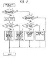
- a flow chart in FIG.3 shows a control routine of the above - described braking controls which are performed by the vehicle control unit 20.
- step 1 when an exhaust braking regenerative time, namely the exhaust braking switch 26 is on, is judged, the process goes to step 2, wherein the engine clutch is connected and then in step 3, it is judged whether or not a charging voltage of the capacitor 16 is in a full charging state exceeding a predetermined value.
- step 4 When it is judged that the charging voltage is in a full charging state, the process goes to step 4, wherein the engine control unit 20 issues a command to operate the exhaust brake 27. On the other hand, when it is judged that it is not in a full charging state, the process goes to step 5, wherein the engine control unit 10 switches off the exhaust brake 27 and makes the motor 2 generate the regenerative power, whereby the braking force the same as the exhaust brake 27 is generated.
- step 6 When it is judged in step 1 that it is not the exhaust braking regenerative time, the process goes to step 6, wherein it is judged whether or not it is an engine braking regenerative time.
- step 7 it is judged whether or not a charging voltage of the capacitor 16 is in a full charging state exceeding a predetermined value.
- step 7 When it judged that it is in a full charging state in step 7, the process goes to step 8, wherein the engine control unit 10 connects the engine clutch 3 to generate what is called an engine braking by the engine 1.
- step 7 when it is judged that in step 7 it is not in a full charging state, the process goes to step 9, wherein the regenerative power generation is performed by the motor 2.
- the motor 2 performs the regenerative power generation without an operation of the exhaust brake 27 and thereby a power corresponding to the braking energy of the exhaust brake 27 is regenerated and a kinetic energy of a vehicle can be effectively recovered.
- the motor 2 can regenerate a power of braking energy corresponding to an engine braking.
- FIG.4 is an explanatory view showing a concept of a braking system, which will be explained.
- a relation between a braking pedal pressure and a deceleration is determined based upon experiment data, and based upon this relation, a map 42 setting a relation between a braking pedal pressure and a deceleration energy of a vehicle is set.
- a demand deceleration energy is determined in response to a braking pedal pressure detected by braking pressure sensors 59, 69 using the map 42.
- a braking sharing ratio and a regenerative braking characteristic are selected based upon the demand deceleration energy, a shift position of the transmission 4 detected by a gear position sensor 23, a vehicle speed detected by a vehicle speed sensor 25, a torque characteristic of the motor 2, and a state of charge of the capacitor 16 with reference to a map 43 in which a sharing ratio of the regenerative braking force of the motor 2 and the braking force of each braking actuator 57, 67 is set.
- a deceleration energy that the front wheel-side braking actuator 57 and the rear wheel-side actuator 67 share is calculated based upon the braking sharing ratio in a calculation section 46.
- the front wheel braking pressure and the rear wheel braking pressure are determined based upon the calculation result with reference to the preset maps 44, 45, and an operation of each proportional valve (braking pressure adjustment mechanism) 53, 63 is feedback-controlled for obtaining the above braking pressure.
- the regenerative energy of the motor 2 is calculated from the regenerative braking force determined from the map 43 in a calculation section 47 and an output command is given to the inverter 15 for obtaining the regenerative energy. Thereby the regenerative power generation is performed by the motor 2.
- FIG.5A shows that a vehicle speed reduces from a high value as viewed from the left side to the right side, and finally the vehicle stops.
- a braking force by the braking actuator 57 and a regenerative braking force of the motor 2 are controlled to be distributed so that at a main braking demand when the braking pedal is depressed, the required deceleration energies are obtained by the braking force of the front wheel 6 generated by the braking actuator 57 and the braking force generated by the regenerative power of the motor 2, which are distributed in a ratio of substantially 3 to 7.
- the required deceleration energies are obtained by the braking force of the front wheel 6 generated by the braking actuator 57 and the braking force generated by the regenerative power of the motor 2, which are distributed in a ratio of substantially 3 to 7.
- a distribution ratio of the braking force applied to the front wheel 6 and the rear wheel 7 is substantially 3 to 7, which is a value as a limit value within which the ABS modulator does not operate when the braking is performed with a deceleration of 0.4G on a road surface having a friction coefficient of 0.1 ⁇
- a ratio of the braking force applied to the front wheel 6 and the rear wheel 7 is substantially 3 to 7 during vehicle traveling, a braking stability is ensured even when a vehicle travels on a slippery road such as a frozen road, to reduce an operation frequency of the ABS modulator.
- the distribution control of the braking force is supplemented by the braking actuator 67 of the rear wheel 7.
- the braking force is generated also by the braking actuator 67 of the rear wheel 7, and thereby when the regenerative energy of the motor 2 gradually reduces during vehicle deceleration, the braking force by the braking actuator 67 ensures the deceleration energy as a whole to maintain a stable braking performance.
- FIG.6 is a calculation block diagram showing control contents performed in the vehicle control unit 20 for distributing the above-described braking force.
- FIG.6 shows a demand braking force calculation circuit section 81 which calculates a demand deceleration energy in response to a braking pedal pressure detected by braking pressure sensors 59, 69 and a demand braking force distribution circuit section 82 which distributes the calculated demand deceleration energy to the front wheel 6 and the rear wheel 7 a distribution ratio of which is substantially 3 to 7.
- a braking force calculation section 83 which calculates a motor braking force generating in response to a rotation speed of the motor 2 is provided.
- a rotation speed calculation circuit section 80 calculating an engine rotation speed based upon a vehicle speed
- an engine braking calculation circuit section 84 calculating an engine braking force generating in response to an engine rotation speed
- an exhaust braking force calculation circuit section 85 calculating an exhaust braking force in response to an engine rotation speed are provided, and these engine braking force and exhaust braking force are added in an addition circuit section 86.
- a subtracter 87 subtracting an addition value of the engine braking force and the exhaust braking force from the motor braking force of the motor braking force calculation circuit section 83 is provided, and a motor braking torque output circuit section 89 outputs this subtracted value as a motor braking torque.
- a subtracter 88 subtracting the motor braking torque from the demand braking force distributed to the rear wheel 7 by the demand braking force distribution circuit section 82 is provided, and a duty signal is outputted to the rear wheel proportional valve 63 from a duty signal output circuit section 90 outputting a duty signal in response to the subtracted value, and further, a duty signal is outputted to the front wheel proportional valve 53 from a duty signal output circuit section 91 outputting a duty signal in response to a demand braking force distributed to the front wheel 6.
- a flow chart in FIG. 7 shows a control routine distributing the above-described braking force.
- the demand braking force is calculated based upon the demand deceleration energy (braking energy) corresponding to the braking pedal pressure detected by the braking pressure sensors 59, 69.
- the process goes to step 12, wherein the calculated demand braking force is distributed to the front wheel 6 and the rear wheel 7 in a ratio of substantially 3 to 7.
- step 13 a control pressure of the front wheel proportional valve 53 is calculated by PI control so as to obtain a control pressure in response to the demand braking force distributed to the front wheel 6.
- step 21 a deviation between the front wheel-side proportional control pressure and a target pressure is extracted, in step 22 an integral operation amount I is extracted by multiplying the deviation over an integral gain, and further, in step 23 a proportional operation amount P is extracted by multiplying the deviation over a proportional gain.
- step 24 an operation amount is extracted by adding the integral operation amount I to the proportional operation amount P, in step 25 a control pressure is calculated by adding the target pressure to the operation amount, and in step 26 the control pressure is extracted by being converted into the control pressure of the proportional pressure.
- step 14 in FIG.7 wherein a braking force is calculated by adding the engine braking force to the exhaust braking force, which is calculated by performing the subroutines in FIGS. 10 and 11 to be described later.
- step 15 an output possible braking force of the motor 2 is calculated, and next in step 16 the motor braking force is subtracted from the demand braking force distributed to the rear wheel 7.
- step 17 wherein the motor braking force is converted into a torque command value ACST of the motor 2.
- step 18 wherein steps 31 - 36 in a subroutine shown in FIG. 9 are performed and thereby a control pressure of the rear wheel proportional valve 63 is controlled by PI control so that a target pressure corresponding to the demand braking force distributed to the rear wheel 7 can be obtained.
- the subroutine in FIG.9 is substantially the same as the subroutine in FIG.8, wherein the steps 31 - 36 in FIG.9 correspond to the steps 21 - 26, which differ only in that a control object is a control signal of the proportional pressure of the rear wheel side from the steps in FIG.8. Accordingly a detailed explanation in FIG.9 is omitted in reference to FIG.8.
- step 19 control signals of the motor 2, the front wheel proportional valve 53, and the rear wheel proportional valve 63 are outputted.
- a flow chart in FIg.10 shows a routine controlling an operation of the exhaust brake 27.
- step 51 a required exhaust braking torque value EXB is calculated from an engine rotation of a vehicle speed conversion.
- step 52 the exhaust braking torque value EXB is converted into the torque command value ACST of the motor 2. Then the process goes to step 53, wherein it is judged whether or not it is a regenerative exhaust braking time when the exhaust braking switch 26 is on.
- step 54 When the exhaust braking switch 26 is on, the process goes to step 54, wherein it is judged whether or not an engine rotation number is equal to or more than 800rpm. When the engine rotation number is equal to or more than 800rpm, the process goes to step 55, wherein it is judged that an accelerator is off. When it is judged that the accelerator is off, the process goes to step 56, wherein it is judged whether or not a gear position of the transmission 4 is established.
- step 57 When the gear position is established, the process goes to step 57, wherein it is judged whether or not the engine clutch 3 is connected.
- step 58 When the engine clutch 3 is connected, the process goes to step 58, wherein it is judged whether or not a charging voltage of the capacitor (ECS) 16 is in a full charging state exceeding a predetermined value.
- ECS capacitor
- step 59 When the capacitor 16 is in a full charging state, the process goes to step 59, wherein a command is given to the engine control unit 10 for operating the exhaust brake 27, and in step 60 an exhaust braking torque value EXB is set as zero.
- step 58 when it is judged that the capacitor 16 is not in a full charging state, the process goes to step 61, wherein when it is judged that the emergency switch 28 is off.
- step 61 When it is in an emergency mode, the process goes to a step after step 59, wherein the exhaust braking operation the same as the above is performed.
- step 62 when it is not in the emergency mode, the process goes to step 62, wherein it is judge that an ABS modulator is not operating. Namely it is confirmed that an anti-braking control is not performed.
- step 63 a command to stop the exhaust brake 27 is given to the engine control unit 10 and in step 64 the exhaust braking torque value EXB is set as a calculation value for the regenerative power generation by the motor 2.
- step 65 the exhaust braking torque value EXB is set as zero and the exhaust brake 27 is adapted to be operated, not the regenerative power generation by the motor 2.
- FIG. 11 shows a routine controlling an operation of an engine braking.
- step 71 a required engine braking torque value ENB is calculated from an engine rotation speed converted from the vehicle speed.
- the process goes to step 72, wherein the engine braking torque value ENB is converted into the torque command value ACST corresponding to the regenerative torque by the motor 2.
- step 73 it is judged whether or not the engine clutch 3 is disconnected.
- step 74 it is judged whether or not a gear position of the transmission 4 is established.
- step 75 it is judged that a gear position is not in a neutral position. In case these conditions all are met, the process goes to step 76, wherein it is judged whether or not the capacitor 16 is in a full charging state.
- step 76 If in step 76 the capacitor 16 is in a full charging state, in step 77 the engine braking torque value ENB is set as zero and the regenerative power generation by the motor 2 is not performed.
- step 78 the engine braking torque value ENB is set as a calculation value for the regenerative power generation by the motor 2.
- step 79 the engine braking torque value ENB is set as zero and the regenerative power generation by the motor 2 is not performed.
- FIG.12 shows a routine controlling the regenerative power generation of the motor 2.
- a maximum torque command value MTR-MAX is calculated based upon an output possible maximum motor torque value ACST from a rotation speed of the motor 2 in step 81.
- the process goes to step 82, wherein the motor braking torque value MTR-RTD is calculated by subtracting the exhaust braking torque value EXB and the engine braking torque value ENB calculated as the above from the maximum torque command value MTR-MAX.
- step 83 it is judged whether or not the capacitor 16 is in a full charging state.
- step 84 the motor braking torque value MTR is set as zero. Namely the motor regenerative power generation stops.
- step 86 it is judged that the emergency switch 28 is off
- step 87 it is judged that the ABS modulator is not operating
- step 88 it is judged that the engine clutch 3 is not disconnected.
- step 89 the motor braking torque command value MTR-RTD calculated above is set to the engine control unit 10 for operating the regenerative power generation by the motor 2.
- step 84 the motor braking torque value MTR is set as zero. Finally the process goes to step 85, wherein the braking torque value MTR-RTD is converted into the braking force.
- the regenerative power generation by the motor 2 is performed as long as a predetermined condition is met, thereby to produce a braking force of the rear wheel side.
- FIG.13 is a time chart showing a control example where the braking force is distributed as described above.
- the vehicle speed reduces as a result of starting the braking.
- the motor regenerative energy also reduces due to the reduction of the vehicle speed and as a result, the motor regenerative energy is not sufficient as the rear wheel-side deceleration energy required (braking energy), and therefore, the rear wheel-side braking force is generated at that point. Thereby the braking force of the rear wheel side is produced by the motor 2 and the rear wheel-side braking actuator.
- the required braking energy is generated by the regenerative power generation by the motor 2, and the front wheel-side and the rear wheel-side actuator to certainly generate the required braking torque. And then since the braking force between the front wheel side and rear wheel side is distributed properly, a stable braking can be performed without slip of a vehicle even on a slippery road such as a frozen road.
- the vehicle control unit 20 stops the automatic braking control and can return the braking system back to a manual braking control.
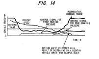
- FIG.14 is a time chart where when a vehicle speed is, for example, equal to or more than 3km during deceleration of a vehicle travel, a braking air pressure is controlled by the proportional valves 53, 63 and as described above, the motor regenerative power generation and the automatic braking control of the front wheel-side and the rear wheel-side braking pressure are performed.
- the cutting valves 52, 62 are opened and in this condition the braking air pressure control by the proportional valves 53, 63 are stopped. Therefore, the braking control is switched into a manual braking control by the braking valve 41.
- a manual braking control is performed, not an automatic braking control, and thereby the braking force can be controlled accurately with a braking operation by a driver, to avoid damage of a braking feeling.
- the present invention can be applied to a braking device of a hybrid vehicle.
Abstract
Description
- The present invention relates to an improvement of a braking system for a hybrid vehicle which selectively switches an engine and an electric-powered motor as a power source of a vehicle.
- There is a known hybrid vehicle disclosed by Japanese Unexamined Patent Publication No. 2000 - 332963A which is equipped with a motor connected to an output shaft of an engine where an electric power is supplied to the motor during vehicle acceleration and operates as an electric generator during vehicle deceleration and vehicle braking for performing regenerative braking, and an accumulator is charged with a generated electric power.
- However, in case in such a known hybrid vehicle, during a main braking demand when a braking pedal is depressed, almost all of braking forces required are supplied by a regenerative braking based upon prioritizing the regenerative power of a motor, or the motor is operated to generate a regenerative power and at the same time a driving wheel is braked, a braking force of the driving wheel increases extensively. As a result, when a vehicle travels on a slippery road such as a frozen road, the driving wheels slip, to lose vehicle stability during vehicle braking.
- An object of the present invention is to provide a braking system for a hybrid vehicle which ensures stability of vehicle braking during vehicle traveling on a slippery road.
- The present invention is provided with a hybrid vehicle including an engine, a motor, and an accumulator to accumulate an electric power which drives the motor comprising a vehicle driving wheel to which rotation of the motor is transmitted, a vehicle driven wheel, a braking actuator which brakes the driving and driven wheels, a control device which changes a braking force of the braking actuator respectively for the driving and driven wheels, and a controller for braking. The controller calculates a braking energy required based upon a vehicle operating condition in demanding a braking and performs the motor to generate a regenerative power so as to produce the calculated braking energy, as well as controls the braking force of the driven wheel.
- The required braking force in demanding the braking is obtained by the regenerative power of the motor connected to the driving wheel, and a driving force by the braking actuator which brakes the driven wheel, which prevents the braking force of a driving wheel side from being excessive, thereby to carry out a stable braking performance on vehicle travel conditions such as a frozen road on which a vehicle tends to slip.
- FIG.1 is a system construction view showing a schematic construction of an embodiment according to the present invention.
- FIg.2 is a block diagram showing control contents of the embodiment.
- FIG.3 is a flow chart showing control contents of the embodiment.
- FIG.4 is a schematic view showing a control concept of the embodiment.
- FIG.5 is a pattern diagram showing a relation of a braking force distribution of the embodiment.
- FIG.6 is a control block diagram distributing a braking force of the embodiment.
- FIG.7 is a flow chart showing a control content distributing the braking force of the embodiment.
- FIG.8 is a flow chart showing a control content of a front wheel proportional valve.
- FIG.9 is a flow chart showing a control content of a rear wheel proportional valve.
- FIG.10 is a flow chart showing a control content of a regenerative exhaust brake.
- FIG.11 is a flow chart showing a control content of a regenerative engine brake.
- FIG.12 is a flow chart showing a control content of a regenerative power generation of a motor.
- FIG.13 is a time chart showing a braking control state by a braking force distribution.
- FIG.14 is a time chart showing a control content to lift an automatic braking control in an extremely low speed of a vehicle.
- A preferred embodiment of the present invention will be explained with reference to accompanying drawings as follows.
- As shown in FIG. 1, a power train of a vehicle is provided with an
engine 1, anengine clutch 3, and atransmission 4. An output of theengine 1 is transmitted to an input shaft of thetransmission 4 through theengine clutch 3, and a rotation of an output shaft of thetransmission 4 is transmitted through a propeller shaft, adifferential gear 5 and a drive shaft to a right side and left side rear wheels (driving wheel)7. - The
engine 1 is an internal combustion engine which burns fuel to be supplied inside a cylinder and rotates/drives an output shaft of theengine 1 by a reciprocal movement of a piston in the cylinder. - An
engine control unit 10 is provided for controlling the output of theengine 1, and controls a fuel supply amount based upon a detecting signal of anengine rotation sensor 13 or various control signals from avehicle control unit 20 to be described later to adjust the output of theengine 1. - The
engine clutch 3 performs connection and disconnection between the engine output shaft and the transmission input shaft through aclutch booster 8. Theclutch booster 8, as shown in FIG.4, disconnects theengine clutch 3 by pressurized air introduced from aclutch actuator 18 by switching aclutch valve 19, and connects theengine clutch 3 by communicating theclutch valve 19 to an open air. - Due to connection of the
engine clutch 3 the engine output is transmitted to thetransmission 4 to driverear wheels 7. - Further, a power train of the vehicle is provided with a
motor 2, amotor clutch 12, and agear device 13 where a rotation of themotor 2 is transmitted to the transmission input shaft through themotor clutch 12 and thegear device 13. - The
motor 2 is an alternator such as a three-phase synchronous motor or a three-phase induction motor and is driven by aninverter 15. And themotor 2 operates as a power generator by theinverter 15 during vehicle deceleration and performs a regenerative power generation. - The
inverter 15 is connected to an electric double layeredcapacitor 16 as a power accumulator and converts a DC charge power of thecapacitor 16 into an AC power, which is supplied to themotor 2, as well as converts an AC power of themotor 2 into a DC power, which charges thecapacitor 16. - However, the accumulator is not limited to the
capacitor 16, but may be various batteries using a chemical reaction. And themotor 2 may be driven by a DC/DC converter using a DC generator, not limited to the alternator. - A braking system mounted on a vehicle is equipped with a
braking valve 41 operated by a driver to adjust a braking air pressure, and thebraking valve 41 generates the braking air pressure for front and rear wheels. Thebraking valve 41 is provided with a front wheelbraking pressure passage 50 introducing the braking air pressure for the front wheel into a frontwheel braking booster 51, and a rear wheelbraking pressure passage 60 introducing the braking air pressure for the rear wheel into a rearwheel braking booster 61. - The
braking valve 41 generates a front wheel-side braking pressure and a rear wheel-side braking pressure each in response to a depressed amount of a braking pedal by a driver. - Along the way of the rear wheel
braking pressure passage 60 are interposed acutting valve 62 cutting off the braking air pressure for the rear wheel in thebraking valve 41 , and aproportional valve 63 adjusting the braking air pressure based upon a command from thevehicle control unit 20 to be described later. And abypass passage 64 introducing the braking air pressure of thebraking valve 41 to the rearwheel braking booster 61 by bypassing theproportional valve 63 is provided, and adouble check valve 65 selects a higher pressure out of a pressure introduced from theproportional valve 63 and a pressure introduced from thebypass passage 64, and introduces the selected pressure to the rearwheel braking booster 61 is provided. - It is to be noted that in FIG.1, a
reservoir tank 70 is an air pressure source for thebraking valve 41 and theproportional valves - And along the halfway of the front wheel
braking pressure passage 50, acutting valve 52 to block a braking air pressure for the front wheel of thebraking valve 41 and aproportional valve 53 to adjust the braking air pressure based upon a command of thevehicle control unit 20 are interposed. And abypass passage 54 introducing the braking air pressure of thebraking valve 41 to the frontwheel brake booster 51 by bypassing theproportional valve 53 is provided, and adouble check valve 55 selects a higher pressure out of a pressure introduced from theproportional valve 53 and a pressure introduced from thebypass passage 54 and introduces the selected pressure to the frontwheel braking booster 51 is provided. - The
braking boosters braking valve 41 or theproportional valves side braking actuator 57 and a rear-side braking actuator 67 through an ABS (anti braking system) modulator (not shown) to apply a braking force to the front wheels (driven wheels) 6 and therear wheels 7. The ABS modulator connects/disconnects a braking oil pressure introduced into eachbraking actuator wheel - At a manual braking control time when each
braking booster braking valve 41 generated based upon a braking operation by a driver
, thecutting valves vehicle control unit 20 and the braking pressure of thebraking valve 41 is introduced into eachbraking booster - On the other hand, at an automatic braking control time a braking air pressure controlled by the
proportional valves vehicle control unit 20 is introduced into eachbraking booster cutting valves - The
proportional valve vehicle control unit 20. On the other hand, thecutting valve vehicle control unit 20. - And a front wheel-side braking circuit is provided with a
backup passage 71 to introduce the braking air pressure of thebraking valve 41 into the frontwheel braking booster 51 by bypassing thecutting valve 52 and theproportional valve 53, anadaptor valve 72 which opens thebackup circuit 71 as the braking air pressure of thebraking valve 41 exceeds a predetermined value, and adouble check valve 73 which selects a higher pressure out of the pressure introduced from theproportional valve 53 and the pressure introduced from thebackup passage 71 and introduces the selected pressure into the frontwheel braking booster 51. - The
adaptor valve 72 is adapted to open thebackup passage 71 as the braking air pressure of thebraking valve 41 exceeds a predetermined value. Theadaptor valve 72 blocks thebackup passage 71 in a state where the braking pedal is not depressed by a driver extensively, and on the other hand, as the braking pedal is depressed extensively, opens thebackup passage 71 to introduce the braking air pressure of thebraking valve 41 into thefront wheel booster 51. Thereby just in case a control system of thevehicle control unit 20 fails, the braking air pressure of thebraking valve 41 is introduced through theadaptor valve 72 into the frontwheel braking booster 51 to perform a failsafe function by braking thefront wheels 6. - Independently of the above-described vehicle braking system, an
exhaust brake 27 is disposed as a supplementary brake. In theexhaust brake 27, an exhaust shutter is interposed in an exhaust passage where the exhaust shutter is closed to increase an exhaust gas pressure, thereby to increase an engine braking force. - An
engine control unit 10, when anexhaust braking switch 26 becomes on by an operation of theswitch 26 by a driver, closes the exhaust shutter based upon a control signal required from thevehicle control unit 20 to operate theexhaust brake 27. - Further, a supplementary brake may be, for example, a compression pressure opened-type brake to open an exhaust valve for an engine during an intake stroke or other mechanisms besides a device to increase an engine braking force.
- The
vehicle control unit 20 receives an input of information from theengine control unit 10 and theinverter 15, as well as receives inputs of each signal from anemergency switch 28, anexhaust braking switch 26, acceleratoropening angle sensor 22 to detect an acceleration pedal' depressing amount, astroke sensor 24 to detect a stroke amount of theengine clutch 3, agear position sensor 23 to detect a gear position of thetransmission 4, avehicle speed sensor 25 to detect a vehicle speed, avoltage sensor 29 to detect a charging state of acapacitor 16,stop lamps braking pressure passages braking force sensors 59, 69 to detect the braking pressure. Thevehicle control unit 20 controls connection/disconnection of theengine clutch 3 and connection/disconnection of themotor clutch 12 in response to an engine operating condition determined based upon these signals, and further, controls an output of theengine 1 and an output of themotor 2, as well as a braking force by the braking system together. - Further, the
emergency switch 28 switches an activation and a stop of the system by an operation of a driver, and in case a malfunction with regard to the system occurs, theemergency switch 28 stops the control system of thevehicle control unit 20, and in particular returns an automatic control of the control system back to a manual control. - Herein braking control operations of the
vehicle control unit 20 are performed separately during vehicle coasting, in an exhaust braking demand, in a main braking demand, and in both anexhaust brake 27 and a main braking demand as below. -
- A) When an accelerator is off where a depressing amount of an acceleration pedal is less than a predetermined value.
- B) When an exhaust braking is off where the
exhaust braking switch 26 is off. - C) When a main braking is off where a depressing amount of the braking pedal is less than a predetermined value.
- In case the coasting time is judged, the
engine clutch 3 is disconnected and themotor clutch 12 is connected, whereby an AC power of themotor 2 performing a regenerative power generation is controlled through theinverter 15 to generate a power equivalent to a braking force of the engine braking (friction of the engine 1). - On the other hand, when a charging pressure of the
capacitor 16 exceeds a predetermined value, themotor clutch 12 is disconnected and theengine clutch 13 is connected, whereby the braking is performed only by the friction of theengine 1. -
- A) When an accelerator is off where a depressing amount of an acceleration pedal is less than a predetermined value.
- B) When an exhaust braking is on where the
exhaust braking switch 26 is on. - C) When a main braking is off.
- In case the exhaust braking demand is judged, the
engine clutch 3 is connected, the exhaust shutter is opened and themotor clutch 12 is connected, whereby an AC power of themotor 2 performing a regenerative power generation is controlled to generate a power equivalent to a braking force of theexhaust brake 27. - On the other hand, when a charging pressure of the
capacitor 16 exceeds a predetermined value, themotor clutch 12 is disconnected and the exhaust shutter is closed, whereby the braking is performed only by the engine braking. -
- A) When an accelerator is off.
- B) When an exhaust braking is off.
- C) When a main braking is on where a depressing amount of the braking pedal exceeds a predetermined value.
- In case the main braking demand time is judged, the
engine clutch 3 is disconnected, the exhaust shutter is opened and themotor clutch 12 is connected, whereby an AC power of themotor 2 performing a regenerative power generation is controlled to generate a power equivalent to a braking force determined based upon a preset map, as well as the remaining engine braking is performed by each brakingactuator proportional valve - In this case, as described later in particular, during an initial braking time a braking force is generated in the front wheels only, not in the rear wheels and the required braking energy is generated by the regenerative power generation by the
motor 2 and the front wheel-side braking force. - On the other hand, when the charging voltage of the
capacitor 16 exceeds a predetermined value, themotor clutch 12 is disconnected and the braking is performed only by each brakingactuator -
- A) When an accelerator is off.
- B) When an exhaust braking is on.
- C) When a main braking is on.
- In case the
exhaust brake 27 and the main braking demand time are judged, theengine clutch 3 is connected, the exhaust shutter is opened and themotor clutch 12 is connected, whereby an AC power of themotor 2 performing a regenerative power generation is controlled to generate a power equivalent to a braking force determined based upon a preset map, as well as the remaining engine braking is performed by each brakingactuator proportional valve motor 2. - On the other hand, when a charging voltage of the
capacitor 16 exceeds a predetermined value, themotor clutch 12 is disconnected and the exhaust shutter is closed, whereby the braking is performed by the engine braking and each brakingactuator - FIG.2 is a control block diagram to perform controls of 1) and 2) out of the above-described braking controls.
- The
vehicle control unit 20 is provided with acircuit section 31 to judge a regenerative exhaust braking time when theexhaust braking switch 26 is on (exhaust braking demand time), and acircuit section 32 to judge a regenerative engine braking time when theexhaust braking switch 26 is off. Therefore, each of thesecircuit sections exhaust braking switch 26, thevehicle speed sensor 25, theclutch stroke sensor 24, the acceleration pedal'opening angle sensor 22, thegear position sensor 23, and the ECS voltage (capacitor voltage)sensor 29 or the like. - A
circuit section 33 controls connection/disconnection of theengine clutch 3 based upon an output from thecircuit sections clutch cutting circuit 35 for an operation control of aclutch actuator 18 to be operated based upon control signals from each circuit, an engine clutch closedcircuit 36 for an operation control of aclutch valve 19, and acircuit section 34 to control an operation of an exhaust braking are provided. - A flow chart in FIG.3 shows a control routine of the above - described braking controls which are performed by the
vehicle control unit 20. - With this routine, firstly in
step 1, when an exhaust braking regenerative time, namely theexhaust braking switch 26 is on, is judged, the process goes to step 2, wherein the engine clutch is connected and then instep 3, it is judged whether or not a charging voltage of thecapacitor 16 is in a full charging state exceeding a predetermined value. - When it is judged that the charging voltage is in a full charging state, the process goes to step 4, wherein the
engine control unit 20 issues a command to operate theexhaust brake 27. On the other hand, when it is judged that it is not in a full charging state, the process goes to step 5, wherein theengine control unit 10 switches off theexhaust brake 27 and makes themotor 2 generate the regenerative power, whereby the braking force the same as theexhaust brake 27 is generated. - When it is judged in
step 1 that it is not the exhaust braking regenerative time, the process goes to step 6, wherein it is judged whether or not it is an engine braking regenerative time. - Herein when the
exhaust braking switch 26 is off, and also it is judged that a vehicle is during vehicle deceleration and in a coasting time, it is determined that it is the engine braking regenerative time. - In this case, the process goes to step 7, wherein it is judged whether or not a charging voltage of the
capacitor 16 is in a full charging state exceeding a predetermined value. - When it judged that it is in a full charging state in
step 7, the process goes to step 8, wherein theengine control unit 10 connects theengine clutch 3 to generate what is called an engine braking by theengine 1. - On the other hand, when it is judged that in
step 7 it is not in a full charging state, the process goes to step 9, wherein the regenerative power generation is performed by themotor 2. - Thus even in an exhaust braking demand time when the
exhaust braking switch 26 is on, themotor 2 performs the regenerative power generation without an operation of theexhaust brake 27 and thereby a power corresponding to the braking energy of theexhaust brake 27 is regenerated and a kinetic energy of a vehicle can be effectively recovered. - And even in a case other than the exhaust braking demand time, such as in a case of an engine braking demand like a coasting time, the
motor 2 can regenerate a power of braking energy corresponding to an engine braking. - This can reduce a share in braking force of a main braking, to provide sufficient capability of the braking force including a main braking. Further, at an engine braking by this
motor 2, it is possible to stop a fuel supply to theengine 1 to improve a fuel economy of theengine 1. - Next, with regard to the main braking demands of 3) and 4) for the above-described braking control operations, a braking system which divides the braking force into the regenerative braking force of the
motor 2 and the braking force of each brakingactuator - First FIG.4 is an explanatory view showing a concept of a braking system, which will be explained. A relation between a braking pedal pressure and a deceleration is determined based upon experiment data, and based upon this relation, a
map 42 setting a relation between a braking pedal pressure and a deceleration energy of a vehicle is set. - A demand deceleration energy is determined in response to a braking pedal pressure detected by braking
pressure sensors 59, 69 using themap 42. - A braking sharing ratio and a regenerative braking characteristic are selected based upon the demand deceleration energy, a shift position of the
transmission 4 detected by agear position sensor 23, a vehicle speed detected by avehicle speed sensor 25, a torque characteristic of themotor 2, and a state of charge of thecapacitor 16 with reference to amap 43 in which a sharing ratio of the regenerative braking force of themotor 2 and the braking force of each brakingactuator - And a deceleration energy that the front wheel-
side braking actuator 57 and the rear wheel-side actuator 67 share is calculated based upon the braking sharing ratio in acalculation section 46. The front wheel braking pressure and the rear wheel braking pressure are determined based upon the calculation result with reference to thepreset maps - On the other hand, the regenerative energy of the
motor 2 is calculated from the regenerative braking force determined from themap 43 in acalculation section 47 and an output command is given to theinverter 15 for obtaining the regenerative energy. Thereby the regenerative power generation is performed by themotor 2. - In addition, as shown in FIG.5A, in case the demand braking force is generated nearly by the regenerative braking of the
motor 2 with a priority of the regenerative power generation of themotor 2 to produce the required deceleration energy at a main braking demand when the braking pedal is depressed, a vehicle stability is deteriorated when the vehicle is running on a slippery road such as a frozen road because of a strong braking force of therear wheel 7, and as a result, an ABS modulator more frequently operates. - FIG.5A shows that a vehicle speed reduces from a high value as viewed from the left side to the right side, and finally the vehicle stops.
- In this figure, when the main braking demand occurs, since the vehicle speed is high, all required deceleration energies can be covered by the regenerative power generation (RR regeneration) of the
motor 2. As the vehicle speed is reduced, the motor regenerative energies reduce and as a result, the braking energies become insufficient on the whole. Therefore, the front wheel-side and rear wheel-side braking force (FR and RR) are adapted to be operated. And when the vehicle stops, the motor regenerative energies come to zero and the front wheel-side and the rear wheel-side braking force only are applied. - However, as described above, during an initial period of the braking, the braking force generated by the regenerative power by the rear wheel-
side motor 2 becomes excessively large, to deteriorate a braking stability on a slippery road. - Accordingly in the present invention, as shown in FIG.5B, a braking force by the
braking actuator 57 and a regenerative braking force of themotor 2 are controlled to be distributed so that at a main braking demand when the braking pedal is depressed, the required deceleration energies are obtained by the braking force of thefront wheel 6 generated by thebraking actuator 57 and the braking force generated by the regenerative power of themotor 2, which are distributed in a ratio of substantially 3 to 7. In this initial period of the braking the braking by the rear wheel-side braking actuator 67 does not start immediately. - Herein a distribution ratio of the braking force applied to the
front wheel 6 and therear wheel 7 is substantially 3 to 7, which is a value as a limit value within which the ABS modulator does not operate when the braking is performed with a deceleration of 0.4G on a road surface having a friction coefficient of 0.1µ - Thus since at a main braking demand, a ratio of the braking force applied to the
front wheel 6 and therear wheel 7 is substantially 3 to 7 during vehicle traveling, a braking stability is ensured even when a vehicle travels on a slippery road such as a frozen road, to reduce an operation frequency of the ABS modulator. - It is to be noted that as the regenerative energy by the
motor 2 reduces and as a result the above distribution ratio can not be maintained, the distribution control of the braking force is supplemented by thebraking actuator 67 of therear wheel 7. Namely the braking force is generated also by thebraking actuator 67 of therear wheel 7, and thereby when the regenerative energy of themotor 2 gradually reduces during vehicle deceleration, the braking force by thebraking actuator 67 ensures the deceleration energy as a whole to maintain a stable braking performance. - FIG.6 is a calculation block diagram showing control contents performed in the
vehicle control unit 20 for distributing the above-described braking force. - FIG.6 shows a demand braking force
calculation circuit section 81 which calculates a demand deceleration energy in response to a braking pedal pressure detected by brakingpressure sensors 59, 69 and a demand braking forcedistribution circuit section 82 which distributes the calculated demand deceleration energy to thefront wheel 6 and the rear wheel 7 a distribution ratio of which is substantially 3 to 7. - And a braking
force calculation section 83 which calculates a motor braking force generating in response to a rotation speed of themotor 2 is provided. - Further, a rotation speed
calculation circuit section 80 calculating an engine rotation speed based upon a vehicle speed, an engine brakingcalculation circuit section 84 calculating an engine braking force generating in response to an engine rotation speed, and an exhaust braking forcecalculation circuit section 85 calculating an exhaust braking force in response to an engine rotation speed are provided, and these engine braking force and exhaust braking force are added in anaddition circuit section 86. - And a
subtracter 87 subtracting an addition value of the engine braking force and the exhaust braking force from the motor braking force of the motor braking forcecalculation circuit section 83 is provided, and a motor braking torqueoutput circuit section 89 outputs this subtracted value as a motor braking torque. - And a
subtracter 88 subtracting the motor braking torque from the demand braking force distributed to therear wheel 7 by the demand braking forcedistribution circuit section 82 is provided, and a duty signal is outputted to the rear wheelproportional valve 63 from a duty signaloutput circuit section 90 outputting a duty signal in response to the subtracted value, and further, a duty signal is outputted to the front wheelproportional valve 53 from a duty signaloutput circuit section 91 outputting a duty signal in response to a demand braking force distributed to thefront wheel 6. - A flow chart in FIG. 7 shows a control routine distributing the above-described braking force.
- First the demand braking force is calculated based upon the demand deceleration energy (braking energy) corresponding to the braking pedal pressure detected by the
braking pressure sensors 59, 69. The process goes to step 12, wherein the calculated demand braking force is distributed to thefront wheel 6 and therear wheel 7 in a ratio of substantially 3 to 7. - Thereafter, the process goes to step 13, wherein steps 21 - 26 shown in a subroutine of FIG.8 are performed and thereby, a control pressure of the front wheel
proportional valve 53 is calculated by PI control so as to obtain a control pressure in response to the demand braking force distributed to thefront wheel 6. - Namely in step 21 a deviation between the front wheel-side proportional control pressure and a target pressure is extracted, in
step 22 an integral operation amount I is extracted by multiplying the deviation over an integral gain, and further, in step 23 a proportional operation amount P is extracted by multiplying the deviation over a proportional gain. Instep 24 an operation amount is extracted by adding the integral operation amount I to the proportional operation amount P, in step 25 a control pressure is calculated by adding the target pressure to the operation amount, and instep 26 the control pressure is extracted by being converted into the control pressure of the proportional pressure. - Next, the process goes to step 14 in FIG.7, wherein a braking force is calculated by adding the engine braking force to the exhaust braking force, which is calculated by performing the subroutines in FIGS. 10 and 11 to be described later.
- Next, the process goes to step 15, wherein an output possible braking force of the
motor 2 is calculated, and next instep 16 the motor braking force is subtracted from the demand braking force distributed to therear wheel 7. Then, the process goes to step 17, wherein the motor braking force is converted into a torque command value ACST of themotor 2. The process goes to step 18, wherein steps 31 - 36 in a subroutine shown in FIG. 9 are performed and thereby a control pressure of the rear wheelproportional valve 63 is controlled by PI control so that a target pressure corresponding to the demand braking force distributed to therear wheel 7 can be obtained. - The subroutine in FIG.9 is substantially the same as the subroutine in FIG.8, wherein the steps 31 - 36 in FIG.9 correspond to the steps 21 - 26, which differ only in that a control object is a control signal of the proportional pressure of the rear wheel side from the steps in FIG.8. Accordingly a detailed explanation in FIG.9 is omitted in reference to FIG.8.
- Then, the process goes to step 19, wherein control signals of the
motor 2, the front wheelproportional valve 53, and the rear wheelproportional valve 63 are outputted. - A flow chart in FIg.10 shows a routine controlling an operation of the
exhaust brake 27. - First in step 51 a required exhaust braking torque value EXB is calculated from an engine rotation of a vehicle speed conversion. In
step 52 the exhaust braking torque value EXB is converted into the torque command value ACST of themotor 2. Then the process goes to step 53, wherein it is judged whether or not it is a regenerative exhaust braking time when theexhaust braking switch 26 is on. - When the
exhaust braking switch 26 is on, the process goes to step 54, wherein it is judged whether or not an engine rotation number is equal to or more than 800rpm. When the engine rotation number is equal to or more than 800rpm, the process goes to step 55, wherein it is judged that an accelerator is off. When it is judged that the accelerator is off, the process goes to step 56, wherein it is judged whether or not a gear position of thetransmission 4 is established. - When the gear position is established, the process goes to step 57, wherein it is judged whether or not the
engine clutch 3 is connected. When theengine clutch 3 is connected, the process goes to step 58, wherein it is judged whether or not a charging voltage of the capacitor (ECS) 16 is in a full charging state exceeding a predetermined value. - When the
capacitor 16 is in a full charging state, the process goes to step 59, wherein a command is given to theengine control unit 10 for operating theexhaust brake 27, and instep 60 an exhaust braking torque value EXB is set as zero. - On the other hand, in
step 58 when it is judged that thecapacitor 16 is not in a full charging state, the process goes to step 61, wherein when it is judged that theemergency switch 28 is off. When it is in an emergency mode, the process goes to a step afterstep 59, wherein the exhaust braking operation the same as the above is performed. - On the other hand, when it is not in the emergency mode, the process goes to step 62, wherein it is judge that an ABS modulator is not operating. Namely it is confirmed that an anti-braking control is not performed.
- In case these conditions all are met, the process goes to step 63, wherein a command to stop the
exhaust brake 27 is given to theengine control unit 10 and instep 64 the exhaust braking torque value EXB is set as a calculation value for the regenerative power generation by themotor 2. - And in case one of the conditions in steps 53 - 57 is not met, in
step 65 the exhaust braking torque value EXB is set as zero and theexhaust brake 27 is adapted to be operated, not the regenerative power generation by themotor 2. - Next, a flow chart in FIG. 11 shows a routine controlling an operation of an engine braking.
- First in step 71 a required engine braking torque value ENB is calculated from an engine rotation speed converted from the vehicle speed. The process goes to step 72, wherein the engine braking torque value ENB is converted into the torque command value ACST corresponding to the regenerative torque by the
motor 2. - The process goes to step 73, wherein it is judged whether or not the
engine clutch 3 is disconnected. When the clutch is not connected, the process goes to step 74, wherein it is judged whether or not a gear position of thetransmission 4 is established. When the gear position is established, the process goes to step 75, wherein it is judged that a gear position is not in a neutral position. In case these conditions all are met, the process goes to step 76, wherein it is judged whether or not thecapacitor 16 is in a full charging state. - If in
step 76 thecapacitor 16 is in a full charging state, instep 77 the engine braking torque value ENB is set as zero and the regenerative power generation by themotor 2 is not performed. - On the other hand, when it is judged that the
capacitor 16 is not in a full charging state, the process goes to step 78, wherein the engine braking torque value ENB is set as a calculation value for the regenerative power generation by themotor 2. - And in case one of these conditions in steps 73 - 75 is not met, in
step 79 the engine braking torque value ENB is set as zero and the regenerative power generation by themotor 2 is not performed. - Further, a flow chart in FIG.12 shows a routine controlling the regenerative power generation of the
motor 2. - First a maximum torque command value MTR-MAX is calculated based upon an output possible maximum motor torque value ACST from a rotation speed of the
motor 2 instep 81. The process goes to step 82, wherein the motor braking torque value MTR-RTD is calculated by subtracting the exhaust braking torque value EXB and the engine braking torque value ENB calculated as the above from the maximum torque command value MTR-MAX. - Then the process goes to step 83, wherein it is judged whether or not the
capacitor 16 is in a full charging state. When thecapacitor 16 is in a full charging state, the process goes to step 84, wherein the motor braking torque value MTR is set as zero. Namely the motor regenerative power generation stops. - On the other hand, it is judged that the
capacitor 16 is not in a full charging state, the process goes to step 86, wherein it is judged that theemergency switch 28 is off, the process goes to step 87, wherein it is judged that the ABS modulator is not operating, further the process goes to step 88, wherein it is judged that theengine clutch 3 is not disconnected. - In case these conditions all are not met, the process goes to step 89, wherein the motor braking torque command value MTR-RTD calculated above is set to the
engine control unit 10 for operating the regenerative power generation by themotor 2. - On the other hand, in case one of these conditions in steps 86 - 88 is met, in
step 84 the motor braking torque value MTR is set as zero. Finally the process goes to step 85, wherein the braking torque value MTR-RTD is converted into the braking force. - Thus at a braking time when the braking pedal is depressed, the regenerative power generation by the
motor 2 is performed as long as a predetermined condition is met, thereby to produce a braking force of the rear wheel side. - FIG.13 is a time chart showing a control example where the braking force is distributed as described above.
- Since travel of a vehicle is performed by the
motor 2, themotor 2 is consuming the power. When the braking pedal is depressed in the vicinity of time (5), a motor consumption power changes into a negative side to perform the regenerative power generation by themotor 2. Thereby a braking force of the rear wheel side is produced. At the same time a braking pressure of the front wheel side increases where a braking force distribution between the front wheel side and the rear wheel side is set to be in a ratio of 3 to 7 as described above. - The vehicle speed reduces as a result of starting the braking. The motor regenerative energy also reduces due to the reduction of the vehicle speed and as a result, the motor regenerative energy is not sufficient as the rear wheel-side deceleration energy required (braking energy), and therefore, the rear wheel-side braking force is generated at that point. Thereby the braking force of the rear wheel side is produced by the
motor 2 and the rear wheel-side braking actuator. - When the vehicle stops completely in the vicinity of time (10), and thereafter the braking pedal is released, the braking force of the front wheel side and the rear wheel side is lowered to zero and the motor power is also reduced to zero.
- Since thus the distribution of the braking force is performed, the required braking energy is generated by the regenerative power generation by the
motor 2, and the front wheel-side and the rear wheel-side actuator to certainly generate the required braking torque. And then since the braking force between the front wheel side and rear wheel side is distributed properly, a stable braking can be performed without slip of a vehicle even on a slippery road such as a frozen road. - Further, in case in the above-described automatic braking control the vehicle speed is reduced to a extremely low value, for example, a speed of less than 3 - 5km due to the braking, the
vehicle control unit 20 stops the automatic braking control and can return the braking system back to a manual braking control. - FIG.14 is a time chart where when a vehicle speed is, for example, equal to or more than 3km during deceleration of a vehicle travel, a braking air pressure is controlled by the
proportional valves - Thereafter, when the vehicle speed is gradually reduced to, for example, equal to or less than 3km, the cutting
valves proportional valves braking valve 41. - Thus during the vehicle travel in an extremely low speed equal to or less than 3 - 5km, a manual braking control is performed, not an automatic braking control, and thereby the braking force can be controlled accurately with a braking operation by a driver, to avoid damage of a braking feeling.
- The present invention is not limited to the described embodiments and it is apparent for those skilled in the art that various modifications and changes can be made within the scope of the technical spirit of the present invention.
- The present invention can be applied to a braking device of a hybrid vehicle.
Claims (7)
- A braking system for a hybrid vehicle includingan engine, a motor, and an accumulator to accumulate an electric power which drives the motor, comprising:a vehicle driving wheel to which rotation of the motor is transmitted;a vehicle driven wheel;a braking actuator which brakes the driving and driven wheels;a control device which changes a braking force of thebraking actuator respectively for the driving and driven wheels; and
 a controller for braking, wherein:the controller calculates a braking energy required based upon a vehicle operating condition in demanding a braking and performs the motor to generate a regenerative power thereof so as to produce the calculated braking energy, as well as controls a braking force of the driven wheel.
 - The braking system for the hybrid vehicle as defined in claim 1, wherein:the controller distributes the braking force generated in the driving wheel and the driven wheel in demanding the braking so that a distribution ratio of the braking force is substantially 7 to 3.
- The braking system for the hybrid vehicle as defined in claim 2, wherein:the controller generates a driving force by the braking actuator of the driving wheel when the braking force of the driving wheel by the motor does not meet the ratio.
- The braking system for the hybrid vehicle as defined in claim 3, wherein:the controller, when a vehicle speed is less than a predetermined value during vehicle deceleration, distributes the braking force in the driving wheel and the driven wheel so that a distribution ratio of the braking force is substantially 5 to 5.
- The braking system for the hybrid vehicle as defined in claim 3, wherein:the controller, when a vehicle travels in an extremely low speed less than a predetermined value in braking the vehicle, stops a distribution control of the braking force.
- The braking system for the hybrid vehicle as defined in claim 1, wherein:the controller, when it is judged that the accumulator is in a full charging state, stops the regenerative power generation by the motor and generates the braking force in the driving wheel and driven wheel based upon an operation of the braking actuator.
- The braking system for the hybrid vehicle as defined in claim 1, wherein:the braking demand is detected based upon an operation of a braking pedal.
Applications Claiming Priority (3)
| Application Number | Priority Date | Filing Date | Title |
|---|---|---|---|
| JP2002078564 | 2002-03-20 | ||
| JP2002078564A JP3921109B2 (en) | 2002-03-20 | 2002-03-20 | Vehicle hybrid system |
| PCT/JP2003/003436 WO2003078200A1 (en) | 2002-03-20 | 2003-03-20 | Braking system of hybrid vehicle |
Publications (3)
| Publication Number | Publication Date |
|---|---|
| EP1491386A1 true EP1491386A1 (en) | 2004-12-29 |
| EP1491386A4 EP1491386A4 (en) | 2010-04-07 |
| EP1491386B1 EP1491386B1 (en) | 2012-09-12 |
Family
ID=28035588
Family Applications (1)
| Application Number | Title | Priority Date | Filing Date |
|---|---|---|---|
| EP03708671A Expired - Lifetime EP1491386B1 (en) | 2002-03-20 | 2003-03-20 | Braking system of hybrid vehicle |
Country Status (5)
| Country | Link |
|---|---|
| US (1) | US7275795B2 (en) |
| EP (1) | EP1491386B1 (en) |
| JP (1) | JP3921109B2 (en) |
| CN (1) | CN1308161C (en) |
| WO (1) | WO2003078200A1 (en) |
Cited By (4)
| Publication number | Priority date | Publication date | Assignee | Title |
|---|---|---|---|---|
| FR2909957A1 (en) * | 2006-12-18 | 2008-06-20 | Peugeot Citroen Automobiles Sa | Braking method for hybrid vehicle, involves applying dissipative braking torque to wheels, applying additional braking torque to wheels by electric machine, and modulating additional torque based on pedal course and braking pressure |
| WO2010056844A1 (en) * | 2008-11-14 | 2010-05-20 | International Truck Intellectual Property Company, Llc | Service brake control system for optimized regenerative braking of medium or heavy trucks |
| FR2950302A1 (en) * | 2009-09-24 | 2011-03-25 | Peugeot Citroen Automobiles Sa | METHOD FOR MANAGING THE COUPLING OF THE HEAT ENGINE ON A HYBRID MOTOR VEHICLE |
| WO2012172464A1 (en) * | 2011-06-17 | 2012-12-20 | Protean Electric Limited | A brake system |
Families Citing this family (24)
| Publication number | Priority date | Publication date | Assignee | Title |
|---|---|---|---|---|
| US20050151420A1 (en) * | 2001-05-07 | 2005-07-14 | Dale Crombez | Hybrid electric vehicle powertrain with regenerative braking |
| KR100520565B1 (en) * | 2003-11-18 | 2005-10-11 | 현대자동차주식회사 | Method and system for controlling regenerative braking of a four wheel drive electric vehicle |
| JP2005253126A (en) * | 2004-03-01 | 2005-09-15 | Nissan Motor Co Ltd | Brake controller of hybrid vehicle and vehicle mounting that controller |
| JP4742778B2 (en) * | 2004-12-22 | 2011-08-10 | 株式会社アドヴィックス | Brake control device for vehicle |
| JP4188348B2 (en) * | 2005-08-10 | 2008-11-26 | 株式会社日立製作所 | ELECTRIC VEHICLE TRAVEL CONTROL DEVICE AND ELECTRIC TRAVEL CONTROL SYSTEM |
| JP2007126092A (en) * | 2005-11-07 | 2007-05-24 | Nissan Motor Co Ltd | Controller for braking force during coasting travel of hybrid vehicle |
| US20070108838A1 (en) * | 2005-11-14 | 2007-05-17 | Ford Global Technologies, Llc | Regenerative braking control system and method |
| JP4466718B2 (en) * | 2007-11-01 | 2010-05-26 | トヨタ自動車株式会社 | Traveling locus generation method and traveling locus generation device |
| JP4952611B2 (en) * | 2008-02-19 | 2012-06-13 | トヨタ自動車株式会社 | Brake system for vehicles |
| US7913549B2 (en) * | 2008-06-20 | 2011-03-29 | GM Global Technology Operations LLC | Transition from exhaust braking to exhaust particulate filter regeneration in a diesel engine |
| DE102009056160B4 (en) * | 2009-11-27 | 2021-12-09 | Bayerische Motoren Werke Aktiengesellschaft | Method for controlling a drive unit of a motor vehicle |
| JP5560797B2 (en) * | 2010-03-17 | 2014-07-30 | コベルコクレーン株式会社 | Work vehicle traveling device |
| US8688302B2 (en) | 2010-12-31 | 2014-04-01 | Cummins Inc. | Hybrid power system braking control |
| JP5387597B2 (en) * | 2011-03-02 | 2014-01-15 | トヨタ自動車株式会社 | Vehicle control device |
| US20130133965A1 (en) * | 2011-11-30 | 2013-05-30 | Martin T. Books | Vehicle braking management for a hybrid power train system |
| US9296301B2 (en) | 2012-11-24 | 2016-03-29 | Ford Global Technologies, Llc | Environment-aware regenerative braking energy calculation method |
| US9296391B2 (en) * | 2014-03-25 | 2016-03-29 | Ford Global Technologies, Llc | E-drive torque sensing vehicle state estimation methods for vehicle control |
| CN104076810A (en) * | 2014-06-11 | 2014-10-01 | 深圳市元征软件开发有限公司 | Automobile diagnosis method based on mobile phone voice mode |
| KR102286743B1 (en) * | 2014-11-05 | 2021-08-09 | 현대모비스 주식회사 | Method for controlling regenerative brake system for vehicle |
| CN105083255B (en) * | 2015-09-06 | 2017-09-05 | 山东交通学院 | Heavy vehicle braking force automatic regulating device under complex road condition |
| KR102354195B1 (en) * | 2017-08-28 | 2022-01-21 | (주)엠피에스코리아 | Control appratus for drive garbage car PHEV |
| JP6626519B2 (en) * | 2018-01-26 | 2019-12-25 | 株式会社Subaru | Vehicle control device |
| US11001263B2 (en) | 2018-03-07 | 2021-05-11 | Toyota Jidosha Kabushiki Kaisha | Braking force control system, device, and method |
| CN114013422B (en) * | 2021-10-31 | 2023-05-30 | 东风商用车有限公司 | Auxiliary braking system and method of vehicle-mounted engine and vehicle |
Citations (6)
| Publication number | Priority date | Publication date | Assignee | Title |
|---|---|---|---|---|
| US5378053A (en) * | 1993-12-07 | 1995-01-03 | Alliedsignal Inc. | Maximized regenerative braking vehicle braking controller |
| DE19810656A1 (en) * | 1998-03-12 | 1999-09-16 | Itt Mfg Enterprises Inc | Braking control method for electric or hybrid vehicles |
| US6021365A (en) * | 1997-02-04 | 2000-02-01 | Honda Giken Kogyo Kabushiki Kaisha | Method of testing regenerative braking force in electric vehicle |
| US6241326B1 (en) * | 1998-10-28 | 2001-06-05 | Kelsey-Hayes Company | Electronic brake proportioning for a rear wheel anti-lock brake system |
| EP1136310A2 (en) * | 2000-03-24 | 2001-09-26 | Sumitomo (Sei) Brake Systems, Inc. | Control method for a coordinated regenerative brake system |
| US20020030408A1 (en) * | 2000-09-14 | 2002-03-14 | Toyota Jidosha Kabushiki Kaisha | Braking force control apparatus and method of motor vehicle |
Family Cites Families (16)
| Publication number | Priority date | Publication date | Assignee | Title |
|---|---|---|---|---|
| JPH05161209A (en) * | 1991-12-05 | 1993-06-25 | Honda Motor Co Ltd | Brake system for motor vehicle |
| GB9320661D0 (en) * | 1993-10-07 | 1993-11-24 | Lucas Ind Public Limited | Electric vehicle having abs |
| JPH0999820A (en) * | 1995-10-03 | 1997-04-15 | Mitsubishi Motors Corp | Braking device for electric vehicle |
| JPH09104333A (en) * | 1995-10-11 | 1997-04-22 | Toyota Motor Corp | Braking device for electric vehicle |
| JP3305568B2 (en) * | 1996-05-15 | 2002-07-22 | 本田技研工業株式会社 | Electric vehicle braking system |
| JPH10236300A (en) * | 1997-02-25 | 1998-09-08 | Toyota Motor Corp | Braking device for electric vehicle |
| JP3501629B2 (en) * | 1997-07-30 | 2004-03-02 | アイシン精機株式会社 | Electric vehicle braking control device |
| US6325470B1 (en) * | 1997-10-01 | 2001-12-04 | Visteon Global Technologies, Inc. | Method and apparatus for proportioning regenerative braking |
| JP3365301B2 (en) * | 1998-03-19 | 2003-01-08 | トヨタ自動車株式会社 | Vehicle braking energy control apparatus and control method thereof |
| JP3384321B2 (en) | 1998-04-20 | 2003-03-10 | 日産自動車株式会社 | Braking force control device |
| JP3502768B2 (en) * | 1998-06-30 | 2004-03-02 | 日産ディーゼル工業株式会社 | Vehicle brake system |
| JP2000332963A (en) | 1999-05-21 | 2000-11-30 | Denso Corp | Two-dimensional code reader |
| JP3763231B2 (en) * | 1999-06-04 | 2006-04-05 | トヨタ自動車株式会社 | Braking device |
| JP4039146B2 (en) * | 2001-09-27 | 2008-01-30 | 日産自動車株式会社 | Braking control device |
| JP3879650B2 (en) * | 2002-10-15 | 2007-02-14 | 日産自動車株式会社 | Vehicle control device |
| JP3863838B2 (en) * | 2002-11-12 | 2006-12-27 | 本田技研工業株式会社 | Hybrid vehicle |
-
2002
- 2002-03-20 JP JP2002078564A patent/JP3921109B2/en not_active Expired - Lifetime
-
2003
- 2003-03-20 CN CNB038063999A patent/CN1308161C/en not_active Expired - Lifetime
- 2003-03-20 EP EP03708671A patent/EP1491386B1/en not_active Expired - Lifetime
- 2003-03-20 US US10/507,732 patent/US7275795B2/en not_active Expired - Lifetime
- 2003-03-20 WO PCT/JP2003/003436 patent/WO2003078200A1/en active Application Filing
Patent Citations (6)
| Publication number | Priority date | Publication date | Assignee | Title |
|---|---|---|---|---|
| US5378053A (en) * | 1993-12-07 | 1995-01-03 | Alliedsignal Inc. | Maximized regenerative braking vehicle braking controller |
| US6021365A (en) * | 1997-02-04 | 2000-02-01 | Honda Giken Kogyo Kabushiki Kaisha | Method of testing regenerative braking force in electric vehicle |
| DE19810656A1 (en) * | 1998-03-12 | 1999-09-16 | Itt Mfg Enterprises Inc | Braking control method for electric or hybrid vehicles |
| US6241326B1 (en) * | 1998-10-28 | 2001-06-05 | Kelsey-Hayes Company | Electronic brake proportioning for a rear wheel anti-lock brake system |
| EP1136310A2 (en) * | 2000-03-24 | 2001-09-26 | Sumitomo (Sei) Brake Systems, Inc. | Control method for a coordinated regenerative brake system |
| US20020030408A1 (en) * | 2000-09-14 | 2002-03-14 | Toyota Jidosha Kabushiki Kaisha | Braking force control apparatus and method of motor vehicle |
Non-Patent Citations (1)
| Title |
|---|
| See also references of WO03078200A1 * |
Cited By (11)
| Publication number | Priority date | Publication date | Assignee | Title |
|---|---|---|---|---|
| FR2909957A1 (en) * | 2006-12-18 | 2008-06-20 | Peugeot Citroen Automobiles Sa | Braking method for hybrid vehicle, involves applying dissipative braking torque to wheels, applying additional braking torque to wheels by electric machine, and modulating additional torque based on pedal course and braking pressure |
| WO2008087322A2 (en) * | 2006-12-18 | 2008-07-24 | Peugeot Citroën Automobiles SA | Method for braking a hybrid vehicle and method for improving a hybrid vehicle implementing said method |
| WO2008087322A3 (en) * | 2006-12-18 | 2008-10-16 | Peugeot Citroen Automobiles Sa | Method for braking a hybrid vehicle and method for improving a hybrid vehicle implementing said method |
| WO2010056844A1 (en) * | 2008-11-14 | 2010-05-20 | International Truck Intellectual Property Company, Llc | Service brake control system for optimized regenerative braking of medium or heavy trucks |
| US8060287B2 (en) | 2008-11-14 | 2011-11-15 | International Truck Intellectual Property Company, Llc | Service brake control system for optimized regenerative braking of medium or heavy trucks |
| AU2009314044B2 (en) * | 2008-11-14 | 2013-09-19 | International Truck Intellectual Property Company, Llc | Service brake control system for optimized regenerative braking of medium or heavy trucks |
| FR2950302A1 (en) * | 2009-09-24 | 2011-03-25 | Peugeot Citroen Automobiles Sa | METHOD FOR MANAGING THE COUPLING OF THE HEAT ENGINE ON A HYBRID MOTOR VEHICLE |
| WO2011036383A1 (en) * | 2009-09-24 | 2011-03-31 | Peugeot Citroën Automobiles SA | Method for managing the coupling of the heat engine on a hybrid automobile |
| WO2012172464A1 (en) * | 2011-06-17 | 2012-12-20 | Protean Electric Limited | A brake system |
| CN103619676A (en) * | 2011-06-17 | 2014-03-05 | 普罗蒂恩电子有限公司 | A brake system |
| US11104315B2 (en) | 2011-06-17 | 2021-08-31 | Protean Electric Limited | Brake system |
Also Published As
| Publication number | Publication date |
|---|---|
| WO2003078200A1 (en) | 2003-09-25 |
| CN1642772A (en) | 2005-07-20 |
| US7275795B2 (en) | 2007-10-02 |
| EP1491386A4 (en) | 2010-04-07 |
| EP1491386B1 (en) | 2012-09-12 |
| JP2003284203A (en) | 2003-10-03 |
| CN1308161C (en) | 2007-04-04 |
| US20050218717A1 (en) | 2005-10-06 |
| JP3921109B2 (en) | 2007-05-30 |
Similar Documents
| Publication | Publication Date | Title |
|---|---|---|
| EP1491386B1 (en) | Braking system of hybrid vehicle | |
| US8277365B2 (en) | Vehicular braking apparatus | |
| US8042886B2 (en) | Vehicle brake system | |
| US7571967B2 (en) | Brake control apparatus for vehicle | |
| JP3982556B1 (en) | Vehicle braking device | |
| JP4370775B2 (en) | Combined brake coordination controller | |
| CN103189253B (en) | Run the method for brake system, implement the brake system of the method and there is the self-propelled vehicle of this brake system | |
| JP5262777B2 (en) | Brake control device for vehicle | |
| CN102256839B (en) | Brake device for a motor vehicle and method for controlling said brake system | |
| CN103043056B (en) | Control vehicle wheel axle torque method and for its control system | |
| US20120022735A1 (en) | Drive control device for electric vehicle, and electric vehicle | |
| JP2007060761A (en) | Deceleration controller for hybrid car | |
| CN102490617A (en) | Hybrid braking system with active auxiliary braking function and control method | |
| JP4743049B2 (en) | Brake control device for vehicle | |
| JP4539374B2 (en) | Combined brake coordination controller | |
| CN112677772A (en) | Automobile regenerative braking control system and method based on electronic hydraulic braking | |
| US6186253B1 (en) | Brake activated torque disable in hybrid electric vehicles | |
| JP4333205B2 (en) | Combined brake coordination controller | |
| KR20180088979A (en) | Braking control apparatus and method for vehicle | |
| US8777334B2 (en) | Control apparatus for vehicle | |
| JP3933144B2 (en) | Braking control device | |
| JP3814816B2 (en) | Hybrid car | |
| JP3892520B2 (en) | Vehicle deceleration energy recovery device | |
| KR102187631B1 (en) | Braking apparatus and braking control method of vehicle | |
| JP3856302B2 (en) | Vehicle hybrid system |
Legal Events
| Date | Code | Title | Description |
|---|---|---|---|
| PUAI | Public reference made under article 153(3) epc to a published international application that has entered the european phase |
Free format text: ORIGINAL CODE: 0009012 |
|
| 17P | Request for examination filed |
Effective date: 20041019 |
|
| AK | Designated contracting states |
Kind code of ref document: A1 Designated state(s): AT BE BG CH CY CZ DE DK EE ES FI FR GB GR HU IE IT LI LU MC NL PT RO SE SI SK TR |
|
| A4 | Supplementary search report drawn up and despatched |
Effective date: 20100304 |
|
| 17Q | First examination report despatched |
Effective date: 20100702 |
|
| RBV | Designated contracting states (corrected) |
Designated state(s): DE SE |
|
| REG | Reference to a national code |
Ref country code: DE Ref legal event code: R079 Ref document number: 60342085 Country of ref document: DE Free format text: PREVIOUS MAIN CLASS: B60L0007240000 Ipc: B60T0001100000 |
|
| GRAP | Despatch of communication of intention to grant a patent |
Free format text: ORIGINAL CODE: EPIDOSNIGR1 |
|
| RIC1 | Information provided on ipc code assigned before grant |
Ipc: B60T 17/04 20060101ALI20120228BHEP Ipc: B60T 1/10 20060101AFI20120228BHEP Ipc: B60T 17/22 20060101ALI20120228BHEP Ipc: B60T 13/74 20060101ALI20120228BHEP |
|
| RIN1 | Information on inventor provided before grant (corrected) |
Inventor name: MIYATA, TATSUJIC/O NISSAN DIESEL MOTOR CO., LTD. Inventor name: SUZUKI, YUUJIC/O NISSAN DIESEL MOTOR CO., LTD. Inventor name: NISHINA, MITSUHIROC/O NISSAN DIESEL MOTOR CO., LTD |
|
| GRAS | Grant fee paid |
Free format text: ORIGINAL CODE: EPIDOSNIGR3 |
|
| GRAA | (expected) grant |
Free format text: ORIGINAL CODE: 0009210 |
|
| AK | Designated contracting states |
Kind code of ref document: B1 Designated state(s): DE SE |
|
| REG | Reference to a national code |
Ref country code: DE Ref legal event code: R096 Ref document number: 60342085 Country of ref document: DE Effective date: 20121108 |
|
| REG | Reference to a national code |
Ref country code: SE Ref legal event code: TRGR |
|
| PLBE | No opposition filed within time limit |
Free format text: ORIGINAL CODE: 0009261 |
|
| STAA | Information on the status of an ep patent application or granted ep patent |
Free format text: STATUS: NO OPPOSITION FILED WITHIN TIME LIMIT |
|
| 26N | No opposition filed |
Effective date: 20130613 |
|
| REG | Reference to a national code |
Ref country code: DE Ref legal event code: R097 Ref document number: 60342085 Country of ref document: DE Effective date: 20130613 |
|
| PGFP | Annual fee paid to national office [announced via postgrant information from national office to epo] |
Ref country code: DE Payment date: 20220217 Year of fee payment: 20 |
|
| PGFP | Annual fee paid to national office [announced via postgrant information from national office to epo] |
Ref country code: SE Payment date: 20220217 Year of fee payment: 20 |
|
| REG | Reference to a national code |
Ref country code: DE Ref legal event code: R071 Ref document number: 60342085 Country of ref document: DE |
|
| REG | Reference to a national code |
Ref country code: SE Ref legal event code: EUG |