EP1491271B1 - Verfahren zur Herstellung eines Stützblechs für eine Automobilkarosse sowie Vorformling für ein Stützblech - Google Patents
Verfahren zur Herstellung eines Stützblechs für eine Automobilkarosse sowie Vorformling für ein Stützblech Download PDFInfo
- Publication number
- EP1491271B1 EP1491271B1 EP20040013616 EP04013616A EP1491271B1 EP 1491271 B1 EP1491271 B1 EP 1491271B1 EP 20040013616 EP20040013616 EP 20040013616 EP 04013616 A EP04013616 A EP 04013616A EP 1491271 B1 EP1491271 B1 EP 1491271B1
- Authority
- EP
- European Patent Office
- Prior art keywords
- indentations
- bent
- portions
- blank
- approximately
- Prior art date
- Legal status (The legal status is an assumption and is not a legal conclusion. Google has not performed a legal analysis and makes no representation as to the accuracy of the status listed.)
- Expired - Lifetime
Links
- 238000004519 manufacturing process Methods 0.000 title claims description 17
- 238000000034 method Methods 0.000 title claims description 17
- 239000000463 material Substances 0.000 claims description 25
- 238000005452 bending Methods 0.000 claims description 14
- 238000007373 indentation Methods 0.000 claims description 13
- 239000002184 metal Substances 0.000 claims description 10
- 238000005520 cutting process Methods 0.000 description 3
- 238000010790 dilution Methods 0.000 description 2
- 239000012895 dilution Substances 0.000 description 2
- 238000000465 moulding Methods 0.000 description 2
- 238000004080 punching Methods 0.000 description 2
- 238000007493 shaping process Methods 0.000 description 2
- 238000009966 trimming Methods 0.000 description 2
- 238000009825 accumulation Methods 0.000 description 1
- 230000015572 biosynthetic process Effects 0.000 description 1
- 150000001875 compounds Chemical class 0.000 description 1
- 239000000446 fuel Substances 0.000 description 1
- 238000002360 preparation method Methods 0.000 description 1
- 238000003856 thermoforming Methods 0.000 description 1
- 238000009827 uniform distribution Methods 0.000 description 1
Images


Classifications
-
- B—PERFORMING OPERATIONS; TRANSPORTING
- B21—MECHANICAL METAL-WORKING WITHOUT ESSENTIALLY REMOVING MATERIAL; PUNCHING METAL
- B21D—WORKING OR PROCESSING OF SHEET METAL OR METAL TUBES, RODS OR PROFILES WITHOUT ESSENTIALLY REMOVING MATERIAL; PUNCHING METAL
- B21D53/00—Making other particular articles
- B21D53/88—Making other particular articles other parts for vehicles, e.g. cowlings, mudguards
-
- B—PERFORMING OPERATIONS; TRANSPORTING
- B21—MECHANICAL METAL-WORKING WITHOUT ESSENTIALLY REMOVING MATERIAL; PUNCHING METAL
- B21D—WORKING OR PROCESSING OF SHEET METAL OR METAL TUBES, RODS OR PROFILES WITHOUT ESSENTIALLY REMOVING MATERIAL; PUNCHING METAL
- B21D35/00—Combined processes according to or processes combined with methods covered by groups B21D1/00 - B21D31/00
Definitions
- the invention relates to a method for producing a support plate for an automobile body according to claim 1, as well as on a preform for Production of such a support plate according to the preamble of Claim 4.
- the invention has for its object to provide a method for producing a To specify support plates for an automobile body, which has a higher production number guaranteed per unit of time with simultaneous material savings and lesser Quality of the sheet material to be used.
- the bending occurs the flange portions of the preform approximately 90 ° to the wall sections. Finally, the sidewall portions become opposite the middle wall portion bent, again approximately at 90 °.
- This shaping is one Type drawing process.
- the pulling of the recesses and the punching of the Cut can be performed in a timely order, for example, in a single stroke of a drawing and forming press.
- the method described is relatively expensive, as for reasons of stability is required that the lower flange portions are continuous and not interrupted by cuts or the like. If not special measures There is a risk that at the corners there is a tearing comes between the flange sections.
- shaping the recesses is however, a uniform distribution of the initially existing surplus material achieved after completion of the forming process, the wells have disappeared in the area of the flange sections and in the range of Sidewall or center wall portion is received by the bend, the when bending the side wall sections arises. The bend does not occur along a sharp edge, but rather gets in a certain radius bent over to avoid load peaks of the support plate.
- the invention also provides a preform for a support plate with the features of claim 4.
- the preform has two elongated depressions of approximately triangular contour without dilution of the Materials outside or inside the wells. These indentations will be in turn, reshaped when, after bending the flange and the side wall sections the final shape of the support plate is made.
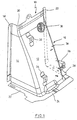
- the support plate 10 shown in perspective in FIG. 1 has a middle wall section 12 and side wall sections 14 and 16, respectively.
- the middle wall section 12 extends obliquely downwards, and the side wall sections 14, 16 are at the Side of the middle wall portion 12 connected.
- the side wall sections 14, 16 Therefore, they widen from top to bottom and stand upright.
- To the rear Edges of the side wall sections 14, 16 adjoin flange sections 18, 20, which are bent approximately 90 ° to the side to the outside.
- the wall sections 12, 14, 16 adjoin flange sections 22, 24, 28, which are formed by right-angled turn to the outside. It can be seen that the Flange sections 22, 24 and 28 are continuous.
- the bending of the individual Wall sections and flange sections are not sharp-edged, but over a radius. In particular, in the region of the connection of the side wall sections 14, 16 formed with the middle wall portion 12 a relatively large radius.
- a support plate 10 of the type shown is the basic structure itself known. He is with the flange portions 22 to 28 on a not shown Bottom plate of an automobile mounted and fastened there and with the side Flange sections 18, 20 attached to a column of the body, which also not is shown. Thus, a channel 30 results between the column and the support body, the z. B. receives a fuel line leading to the tank of the automobile, not shown leads.
- bracket 32 34 are attached to where a panel of the car can be attached.
- a Mother shown for striking the lap belt of a seatbelt for that not shown automobile.
- a Bracket 36 is attached to which a sensor for an airbag is attached.
- a plurality of studs 38 are shown for the attachment of other parts, which is here but not to be described in detail. The following is the production of the support plate 10 described in more detail.
- a sheet metal strip 40 is shown, which gradually in the direction of arrow 42 is moved forward in a forming and drawing press.
- the outline is one Blank shown, from the by several forming operations, the support plate 10 after Fig. 1 is produced.
- a compound tool is indicated, with the help of in the sheet metal strip 40, first two recesses 48 are formed and Subsequently, a preform 50 punched out in the same stroke of the press ram becomes.
- the preform 50 has the sidewall portions 14, 16, the middle wall portion 12 and the flange portions 18, 20 and the flange portions 22, 24, 26 on.
- the described sections are in one level.
- the bending lines 52, 54, 56, 58, 60, to which later described Sections are subsequently bent, are drawn for illustration purposes only. They are not visible on the preform 50.
- the recesses 48 which naturally on the other side of the preform 50th Are elevations are in outline approximately triangular with rounded tip 62. They are rounded in cross-section, and the entire bottom of the recess 48 forms a section of a conical mantle, d. H. decrease away from the free edge the width and depth of the depressions to the top, in the plane of the Sheet metal is lying.
- the lateral flange portions 18, 20 are bent at right angles to the side wall portions 14, 16, and Although the bending lines 52, 54.
- the flange portions 22, 24, 28th bent around the bend line 56. This results in the area 64, 66 in the Flange sections 22, 24, 28, an excess of material, by the bulge in this area is formed.
- the side wall sections 14, 16 are opposite the middle wall portion 12 is bent, wherein the flange portions 18, 20 and 22nd to 28 each outwards. It comes in the 66 and 68 shown Areas to a special burden. But there is enough material due of the bulges 64, 66 is available, it is achieved that the thickness of the Sheets also in the areas 68, 70 has the same size as in the rest Areas of the support plate 10th
- the described manufacturing process allows a saving of material in the Comparison to a production process by deep drawing. This material saving goes up to 50%.
- a manufacturing process requires the described Art a far less high quality material than a thermoforming process.
- Furthermore can be a method of preparation in the manner described to a higher number of units per unit of time.
Landscapes
- Engineering & Computer Science (AREA)
- Mechanical Engineering (AREA)
- Shaping Metal By Deep-Drawing, Or The Like (AREA)
Description
- Fig. 1
- zeigt perspektivisch ein Stützblech, das nach dem erfindungsgemäßen Verfahren hergestellt worden ist.
- Fig. 2
- zeigt die Draufsicht auf einen Blechstreifen und die Herstellung des Vorformlings nach der Erfindung.
- Fig. 3
- zeigt den Vorformling in Draufsicht.
- Fig. 4
- zeigt perspektivisch einen weiteren Verfahrensschritt bei der Bearbeitung des Vorformlings nach Fig. 3.
- Fig. 5
- zeigt perspektivisch das Stützblech, das aus dem Vorformling nach Fig. 3 fertig gebogen worden ist.
Claims (7)
- Verfahren zur Herstellung eines Stützbleches für eine Automobilkarosse, das aus Flachmaterial geformt wird und aus zwei aufrechten Seitenwandabschnitten (14, 16) und einem gegebenenfalls schrägen, die Seitenwandabschnitte an einer Seite verbindenden Mittelwandabschnitt (12) besteht, die annähernd im rechten Winkel zueinander gebogen werden, wobei an den freien seitlichen und unteren Kanten der Wandabschnitte Flanschabschnitte (18, 20) nach außen gebogen werden und wobei die Flanschabschnitte an den unteren Kanten durchgehend geformt werden, mit den folgenden Verfahrensschritten:Im Flachmaterial werden zunächst zwei längliche, annähernd dreieckförmige Vertiefungen geformt ohne eine Verdünnung des Materials innerhalb und außerhalb der Vertiefungen (48), wobei die Vertiefungen an beiden Seiten einer Biegelinie im unteren Bereich des Stützbleches liegen, um welche die Seitenwandabschnitte gegenüber dem Mittelwandabschnitt gebogen werden und sich bis zur freien Kante der unteren Flanschabschnitte erstrecken und an dem von den Kanten abgewandten Ende kontinuierlich in das benachbarte Material übergehen,anschließend ein Vorformling (50) aus dem Flachmaterial ausgestanzt wird,am Vorformling die Flanschabschnitte um etwa 90° nach außen abgebogen werden undschließlich die Seitenwandabschnitte gegenüber dem Mittelwandabschnitt gebogen werden.
- Verfahren nach Anspruch 1, dadurch gekennzeichnet, daß das Formen der Vertiefungen und das Stanzen in einem Hub einer Stanz- und Formpresse durchgeführt wird.
- Verfahren nach Anspruch 1 oder 2, dadurch gekennzeichnet, daß die Biegelinie der unteren Flanschabschnitte annähernd parallel zu den freien Kanten der Flanschabschnitte quer über die Vertiefungen hinweg verläuft.
- Vorformling zur Herstellung eines Stützbleches für eine Automobilkarosse, das aus Flachmaterial geformt ist und aus zwei aufrechten Seitenwandabschnitten (14, 16) und einem gegebenenfalls schrägen, die Seitenwände an einer Seite verbindendem Mittelwandabschnitt (12) besteht, die annähernd um rechte Winkel zueinander gebogen sind, wobei an den freien seitlichen, unteren Kanten der Wandabschnitte Flanschabschnitte nach außen abgebogen sind und wobei die Flanschabschnitte (18, 20) an der unteren Kante durchgehend geformt sind, dadurch gekennzeichnet, daß zwei längliche, annähernd dreieckförmige Vertiefungen (48) geformt sind, deren Blechdicke annähernd gleich groß ist wie die Dicke des benachbarten Materials, daß die Vertiefungen (48) im unteren Bereich des Vorformlings (50) liegen zu beiden Seiten einer Biegelinie (58, 60), um welche bei Erstellung des Stützblechs (10) die Seitenwandabschnitte (14, 16) gegenüber dem Mittelwandabschnitt (12) gebogen werden, daß die Vertiefungen (48) sich zur freien Kante der unteren Flanschabschnitte (22, 24, 28) erstrecken und daß die Vertiefungen (48) an dem von der freien Kante abgewandten Ende allmählich in das benachbarte Material übergehen.
- Vorformling nach Anspruch 4, dadurch gekennzeichnet, daß die Vertiefungen (48) am oberen Ende eine gerundete Spitze aufweisen.
- Vorformling nach Anspruch 4 oder 5, dadurch gekennzeichnet, daß die Vertiefungen die Form eines Abschnitts eines Kegelmantels aufweisen.
- Vorformling nach einem der Ansprüche 4 bis 6, dadurch gekennzeichnet, daß die Vertiefungen (48) symmetrisch zu beiden Seiten der zugeordneten Biegelinie (58, 60) angeordnet sind, wobei die von den freien Kanten abgerundete Spitze (62) annähernd auf der zugeordneten Biegelinie (58, 60) liegt.
Applications Claiming Priority (2)
| Application Number | Priority Date | Filing Date | Title |
|---|---|---|---|
| DE10328901 | 2003-06-26 | ||
| DE2003128901 DE10328901B4 (de) | 2003-06-26 | 2003-06-26 | Verfahren zur Herstellung eines Stützblechs für eine Automobilkarosse sowie Vorformling für ein Stützblech |
Publications (2)
| Publication Number | Publication Date |
|---|---|
| EP1491271A1 EP1491271A1 (de) | 2004-12-29 |
| EP1491271B1 true EP1491271B1 (de) | 2005-11-30 |
Family
ID=33395006
Family Applications (1)
| Application Number | Title | Priority Date | Filing Date |
|---|---|---|---|
| EP20040013616 Expired - Lifetime EP1491271B1 (de) | 2003-06-26 | 2004-06-09 | Verfahren zur Herstellung eines Stützblechs für eine Automobilkarosse sowie Vorformling für ein Stützblech |
Country Status (3)
| Country | Link |
|---|---|
| EP (1) | EP1491271B1 (de) |
| DE (2) | DE10328901B4 (de) |
| ES (1) | ES2252718T3 (de) |
Family Cites Families (4)
| Publication number | Priority date | Publication date | Assignee | Title |
|---|---|---|---|---|
| US5092097A (en) * | 1990-09-10 | 1992-03-03 | United Steel Products Co. | Holddown connector |
| US5249404A (en) * | 1992-05-11 | 1993-10-05 | Simpson Strong-Tie Company, Inc. | Holdown connection |
| DE19728582B4 (de) * | 1997-07-04 | 2007-04-26 | Volkswagen Ag | Verfahren zum Herstellen eines Metallformteils |
| FR2773568B1 (fr) * | 1998-01-13 | 2000-03-24 | Denis Crochet | Dispositif d'assemblage d'elements de structure, comportant une equerre modulable |
-
2003
- 2003-06-26 DE DE2003128901 patent/DE10328901B4/de not_active Expired - Fee Related
-
2004
- 2004-06-09 ES ES04013616T patent/ES2252718T3/es not_active Expired - Lifetime
- 2004-06-09 EP EP20040013616 patent/EP1491271B1/de not_active Expired - Lifetime
- 2004-06-09 DE DE200450000151 patent/DE502004000151D1/de not_active Expired - Lifetime
Also Published As
| Publication number | Publication date |
|---|---|
| DE502004000151D1 (de) | 2006-01-05 |
| DE10328901B4 (de) | 2005-06-30 |
| EP1491271A1 (de) | 2004-12-29 |
| DE10328901A1 (de) | 2005-02-10 |
| ES2252718T3 (es) | 2006-05-16 |
Similar Documents
| Publication | Publication Date | Title |
|---|---|---|
| DE69914775T2 (de) | Verfahren zur Herstellung einer Stossfängerträgeranordnung | |
| DE69906093T2 (de) | Verfahren zum hydroformen von rohrförmigen bauteilen | |
| DE69817149T2 (de) | Ladeplattform eines fahrzeuges | |
| DE2843249B1 (de) | Wischblatt und Verfahren zur Herstellung eines Wischblatts | |
| DE19820473B4 (de) | Verfahren und Vorrichtung zur Herstellung eines im Querschnitt abgekanteten und in Längsrichtung zumindest teilweise gebogenen Produktes | |
| DE69804496T2 (de) | Lasche für behälterdeckel und verfahren zu seiner herstellung | |
| DE2111524A1 (de) | Einpressmuttern in Streifenform und Verfahren zum Herstellen und Anbringen derselben | |
| DE10329424A1 (de) | Verfahren zum Herstellen eines längsgeschlitzten Hohlprofils mit mehreren, im Querschnitt verschiedenen Längsabschnitten aus einer ebenen Blechplatine | |
| EP2025424B1 (de) | Verfahren zur Herstellung eines rohrförmigen Tragprofils für einen Instrumententräger | |
| DE102011112256A1 (de) | Kraftfahrzeug mit Crashbox | |
| EP2108467B1 (de) | Verfahren zur Herstellung von hochmaßhaltigen Halbschalen | |
| DE102017118295A1 (de) | Formpresswerkzeug | |
| EP2542363B1 (de) | Verfahren und vorrichtung zum ziehen und beschneiden von platinen | |
| EP1253983A1 (de) | Bauteil mit lokal begrenzten versteifungsbereichen und verfahren zu seiner herstellung | |
| EP0888835A1 (de) | Verfahren zum Herstellen eines Metallformteils | |
| WO2011009569A1 (de) | Weinbergpfahl | |
| CH635789A5 (de) | Gebinde und verfahren zu seiner herstellung. | |
| EP1180410A2 (de) | Schweissverbindung mit zwei Blechen | |
| DE3229246A1 (de) | Verfahren und vorrichtung zum abstreifen eines randflansches waehrend des behaelternachziehens | |
| DE3428794A1 (de) | Verfahren zur herstellung eines doppelten bundes und ein nach diesem verfahren erhaltenes werkstueck mit doppeltem bund | |
| DE1586449A1 (de) | Verfahren zum Vorkerben eines metallenen Behaelterdeckels | |
| DE10328901B4 (de) | Verfahren zur Herstellung eines Stützblechs für eine Automobilkarosse sowie Vorformling für ein Stützblech | |
| DE19923737A1 (de) | Mehrteilige Stirnwand für eine Kraftfahrzeugrohbaukarosserie | |
| EP1690608B1 (de) | Verfahren und Vorrichtung zur Herstellung von Rohren | |
| WO2016119940A1 (de) | Verfahren und vorrichtung zur herstellung eines kragens an einem werkstück |
Legal Events
| Date | Code | Title | Description |
|---|---|---|---|
| PUAI | Public reference made under article 153(3) epc to a published international application that has entered the european phase |
Free format text: ORIGINAL CODE: 0009012 |
|
| 17P | Request for examination filed |
Effective date: 20040618 |
|
| AK | Designated contracting states |
Kind code of ref document: A1 Designated state(s): AT BE BG CH CY CZ DE DK EE ES FI FR GB GR HU IE IT LI LU MC NL PL PT RO SE SI SK TR |
|
| AX | Request for extension of the european patent |
Extension state: AL HR LT LV MK |
|
| GRAP | Despatch of communication of intention to grant a patent |
Free format text: ORIGINAL CODE: EPIDOSNIGR1 |
|
| GRAS | Grant fee paid |
Free format text: ORIGINAL CODE: EPIDOSNIGR3 |
|
| AKX | Designation fees paid |
Designated state(s): DE ES FR GB IT SE |
|
| GRAA | (expected) grant |
Free format text: ORIGINAL CODE: 0009210 |
|
| AK | Designated contracting states |
Kind code of ref document: B1 Designated state(s): DE ES FR GB IT SE |
|
| REG | Reference to a national code |
Ref country code: GB Ref legal event code: FG4D Free format text: NOT ENGLISH |
|
| REG | Reference to a national code |
Ref country code: SE Ref legal event code: TRGR |
|
| REF | Corresponds to: |
Ref document number: 502004000151 Country of ref document: DE Date of ref document: 20060105 Kind code of ref document: P |
|
| GBT | Gb: translation of ep patent filed (gb section 77(6)(a)/1977) |
Effective date: 20060118 |
|
| REG | Reference to a national code |
Ref country code: ES Ref legal event code: FG2A Ref document number: 2252718 Country of ref document: ES Kind code of ref document: T3 |
|
| ET | Fr: translation filed | ||
| PLBE | No opposition filed within time limit |
Free format text: ORIGINAL CODE: 0009261 |
|
| STAA | Information on the status of an ep patent application or granted ep patent |
Free format text: STATUS: NO OPPOSITION FILED WITHIN TIME LIMIT |
|
| 26N | No opposition filed |
Effective date: 20060831 |
|
| REG | Reference to a national code |
Ref country code: FR Ref legal event code: CD Ref country code: FR Ref legal event code: CA Ref country code: FR Ref legal event code: TP |
|
| REG | Reference to a national code |
Ref country code: GB Ref legal event code: 732E Free format text: REGISTERED BETWEEN 20091217 AND 20091223 |
|
| REG | Reference to a national code |
Ref country code: FR Ref legal event code: TP |
|
| REG | Reference to a national code |
Ref country code: ES Ref legal event code: PC2A Owner name: ITW LIMITED Effective date: 20110307 |
|
| PGFP | Annual fee paid to national office [announced via postgrant information from national office to epo] |
Ref country code: SE Payment date: 20110622 Year of fee payment: 8 Ref country code: ES Payment date: 20110623 Year of fee payment: 8 |
|
| PGFP | Annual fee paid to national office [announced via postgrant information from national office to epo] |
Ref country code: GB Payment date: 20110624 Year of fee payment: 8 |
|
| PGFP | Annual fee paid to national office [announced via postgrant information from national office to epo] |
Ref country code: IT Payment date: 20110620 Year of fee payment: 8 |
|
| PGFP | Annual fee paid to national office [announced via postgrant information from national office to epo] |
Ref country code: FR Payment date: 20110722 Year of fee payment: 8 |
|
| PGFP | Annual fee paid to national office [announced via postgrant information from national office to epo] |
Ref country code: DE Payment date: 20110621 Year of fee payment: 8 |
|
| REG | Reference to a national code |
Ref country code: SE Ref legal event code: EUG |
|
| GBPC | Gb: european patent ceased through non-payment of renewal fee |
Effective date: 20120609 |
|
| PG25 | Lapsed in a contracting state [announced via postgrant information from national office to epo] |
Ref country code: SE Free format text: LAPSE BECAUSE OF NON-PAYMENT OF DUE FEES Effective date: 20120610 Ref country code: IT Free format text: LAPSE BECAUSE OF NON-PAYMENT OF DUE FEES Effective date: 20120609 |
|
| REG | Reference to a national code |
Ref country code: FR Ref legal event code: ST Effective date: 20130228 |
|
| REG | Reference to a national code |
Ref country code: DE Ref legal event code: R119 Ref document number: 502004000151 Country of ref document: DE Effective date: 20130101 |
|
| PG25 | Lapsed in a contracting state [announced via postgrant information from national office to epo] |
Ref country code: FR Free format text: LAPSE BECAUSE OF NON-PAYMENT OF DUE FEES Effective date: 20120702 Ref country code: DE Free format text: LAPSE BECAUSE OF NON-PAYMENT OF DUE FEES Effective date: 20130101 Ref country code: GB Free format text: LAPSE BECAUSE OF NON-PAYMENT OF DUE FEES Effective date: 20120609 |
|
| REG | Reference to a national code |
Ref country code: ES Ref legal event code: FD2A Effective date: 20131022 |
|
| PG25 | Lapsed in a contracting state [announced via postgrant information from national office to epo] |
Ref country code: ES Free format text: LAPSE BECAUSE OF NON-PAYMENT OF DUE FEES Effective date: 20120610 |