EP1491162A2 - A graft fixation device - Google Patents
A graft fixation device Download PDFInfo
- Publication number
- EP1491162A2 EP1491162A2 EP20040253805 EP04253805A EP1491162A2 EP 1491162 A2 EP1491162 A2 EP 1491162A2 EP 20040253805 EP20040253805 EP 20040253805 EP 04253805 A EP04253805 A EP 04253805A EP 1491162 A2 EP1491162 A2 EP 1491162A2
- Authority
- EP
- European Patent Office
- Prior art keywords
- sheath
- graft
- sidewalls
- expandable sheath
- sidewall
- Prior art date
- Legal status (The legal status is an assumption and is not a legal conclusion. Google has not performed a legal analysis and makes no representation as to the accuracy of the status listed.)
- Granted
Links
- 210000000988 bone and bone Anatomy 0.000 claims abstract description 36
- 239000000463 material Substances 0.000 claims description 15
- 238000003780 insertion Methods 0.000 claims description 13
- 239000001506 calcium phosphate Substances 0.000 claims description 10
- QORWJWZARLRLPR-UHFFFAOYSA-H tricalcium bis(phosphate) Chemical compound [Ca+2].[Ca+2].[Ca+2].[O-]P([O-])([O-])=O.[O-]P([O-])([O-])=O QORWJWZARLRLPR-UHFFFAOYSA-H 0.000 claims description 10
- 235000019731 tricalcium phosphate Nutrition 0.000 claims description 9
- 229940078499 tricalcium phosphate Drugs 0.000 claims description 9
- 229910000391 tricalcium phosphate Inorganic materials 0.000 claims description 9
- AEMRFAOFKBGASW-UHFFFAOYSA-N Glycolic acid Chemical compound OCC(O)=O AEMRFAOFKBGASW-UHFFFAOYSA-N 0.000 claims description 6
- JVTAAEKCZFNVCJ-UHFFFAOYSA-N lactic acid Chemical compound CC(O)C(O)=O JVTAAEKCZFNVCJ-UHFFFAOYSA-N 0.000 claims description 6
- 229920000642 polymer Polymers 0.000 claims description 4
- 229920001577 copolymer Polymers 0.000 claims description 3
- 239000004310 lactic acid Substances 0.000 claims description 3
- 235000014655 lactic acid Nutrition 0.000 claims description 3
- 239000000178 monomer Substances 0.000 claims description 3
- PAPBSGBWRJIAAV-UHFFFAOYSA-N ε-Caprolactone Chemical compound O=C1CCCCCO1 PAPBSGBWRJIAAV-UHFFFAOYSA-N 0.000 claims description 3
- 210000003041 ligament Anatomy 0.000 description 22
- 238000000034 method Methods 0.000 description 10
- 230000037431 insertion Effects 0.000 description 8
- 229920001610 polycaprolactone Polymers 0.000 description 5
- 239000004632 polycaprolactone Substances 0.000 description 5
- 229920000954 Polyglycolide Polymers 0.000 description 4
- 210000003127 knee Anatomy 0.000 description 4
- 239000004633 polyglycolic acid Substances 0.000 description 4
- 239000004626 polylactic acid Substances 0.000 description 4
- 210000002303 tibia Anatomy 0.000 description 4
- 239000000203 mixture Substances 0.000 description 3
- 229920000747 poly(lactic acid) Polymers 0.000 description 3
- 210000002435 tendon Anatomy 0.000 description 3
- 210000001519 tissue Anatomy 0.000 description 3
- 210000000689 upper leg Anatomy 0.000 description 3
- 238000004873 anchoring Methods 0.000 description 2
- 210000001264 anterior cruciate ligament Anatomy 0.000 description 2
- 239000000919 ceramic Substances 0.000 description 2
- 238000005336 cracking Methods 0.000 description 2
- 239000011521 glass Substances 0.000 description 2
- 239000007943 implant Substances 0.000 description 2
- 229910052751 metal Inorganic materials 0.000 description 2
- 239000002184 metal Substances 0.000 description 2
- 150000002739 metals Chemical class 0.000 description 2
- 208000027418 Wounds and injury Diseases 0.000 description 1
- 210000003484 anatomy Anatomy 0.000 description 1
- 235000011010 calcium phosphates Nutrition 0.000 description 1
- 238000010276 construction Methods 0.000 description 1
- 230000006378 damage Effects 0.000 description 1
- 230000007423 decrease Effects 0.000 description 1
- 210000003414 extremity Anatomy 0.000 description 1
- 230000003116 impacting effect Effects 0.000 description 1
- 238000002513 implantation Methods 0.000 description 1
- 208000014674 injury Diseases 0.000 description 1
- 238000004519 manufacturing process Methods 0.000 description 1
- 229910044991 metal oxide Inorganic materials 0.000 description 1
- 150000004706 metal oxides Chemical class 0.000 description 1
- 238000012986 modification Methods 0.000 description 1
- 230000004048 modification Effects 0.000 description 1
- 210000000056 organ Anatomy 0.000 description 1
- 229920001245 poly(D,L-lactide-co-caprolactone) Polymers 0.000 description 1
- 210000002967 posterior cruciate ligament Anatomy 0.000 description 1
- 210000004872 soft tissue Anatomy 0.000 description 1
- 230000003068 static effect Effects 0.000 description 1
- 238000001356 surgical procedure Methods 0.000 description 1
Images


Classifications
-
- A—HUMAN NECESSITIES
- A61—MEDICAL OR VETERINARY SCIENCE; HYGIENE
- A61F—FILTERS IMPLANTABLE INTO BLOOD VESSELS; PROSTHESES; DEVICES PROVIDING PATENCY TO, OR PREVENTING COLLAPSING OF, TUBULAR STRUCTURES OF THE BODY, e.g. STENTS; ORTHOPAEDIC, NURSING OR CONTRACEPTIVE DEVICES; FOMENTATION; TREATMENT OR PROTECTION OF EYES OR EARS; BANDAGES, DRESSINGS OR ABSORBENT PADS; FIRST-AID KITS
- A61F2/00—Filters implantable into blood vessels; Prostheses, i.e. artificial substitutes or replacements for parts of the body; Appliances for connecting them with the body; Devices providing patency to, or preventing collapsing of, tubular structures of the body, e.g. stents
- A61F2/02—Prostheses implantable into the body
- A61F2/08—Muscles; Tendons; Ligaments
- A61F2/0811—Fixation devices for tendons or ligaments
- A61F2002/0817—Structure of the anchor
- A61F2002/0823—Modular anchors comprising a plurality of separate parts
- A61F2002/0835—Modular anchors comprising a plurality of separate parts with deformation of anchor parts, e.g. expansion of dowel by set screw
-
- A—HUMAN NECESSITIES
- A61—MEDICAL OR VETERINARY SCIENCE; HYGIENE
- A61F—FILTERS IMPLANTABLE INTO BLOOD VESSELS; PROSTHESES; DEVICES PROVIDING PATENCY TO, OR PREVENTING COLLAPSING OF, TUBULAR STRUCTURES OF THE BODY, e.g. STENTS; ORTHOPAEDIC, NURSING OR CONTRACEPTIVE DEVICES; FOMENTATION; TREATMENT OR PROTECTION OF EYES OR EARS; BANDAGES, DRESSINGS OR ABSORBENT PADS; FIRST-AID KITS
- A61F2/00—Filters implantable into blood vessels; Prostheses, i.e. artificial substitutes or replacements for parts of the body; Appliances for connecting them with the body; Devices providing patency to, or preventing collapsing of, tubular structures of the body, e.g. stents
- A61F2/02—Prostheses implantable into the body
- A61F2/08—Muscles; Tendons; Ligaments
- A61F2/0811—Fixation devices for tendons or ligaments
- A61F2002/0847—Mode of fixation of anchor to tendon or ligament
- A61F2002/0858—Fixation of tendon or ligament between anchor and bone, e.g. interference screws, wedges
-
- A—HUMAN NECESSITIES
- A61—MEDICAL OR VETERINARY SCIENCE; HYGIENE
- A61F—FILTERS IMPLANTABLE INTO BLOOD VESSELS; PROSTHESES; DEVICES PROVIDING PATENCY TO, OR PREVENTING COLLAPSING OF, TUBULAR STRUCTURES OF THE BODY, e.g. STENTS; ORTHOPAEDIC, NURSING OR CONTRACEPTIVE DEVICES; FOMENTATION; TREATMENT OR PROTECTION OF EYES OR EARS; BANDAGES, DRESSINGS OR ABSORBENT PADS; FIRST-AID KITS
- A61F2/00—Filters implantable into blood vessels; Prostheses, i.e. artificial substitutes or replacements for parts of the body; Appliances for connecting them with the body; Devices providing patency to, or preventing collapsing of, tubular structures of the body, e.g. stents
- A61F2/02—Prostheses implantable into the body
- A61F2/08—Muscles; Tendons; Ligaments
- A61F2/0811—Fixation devices for tendons or ligaments
- A61F2002/0876—Position of anchor in respect to the bone
- A61F2002/0888—Anchor in or on a blind hole or on the bone surface without formation of a tunnel
Definitions
- the present invention relates to ligament fixation devices and methods, and more particularly to devices and methods for anchoring ligaments within a bone tunnel.
- Ligaments are tough bands of tissue which serve to connect the articular extremities of bones, or to support or retain organs in place within the body.
- Ligaments are typically composed of coarse bundles of dense white fibrous tissue which are disposed in a parallel or closely interlaced manner, with the fibrous tissue being pliant and flexible, but not significantly extensible.
- ligaments are torn or ruptured as a result of accidents or overexertion. Accordingly, various procedures have been developed to repair or replace such damaged ligaments.
- the anterior and posterior cruciate ligaments i.e., the ACL and PCL
- the ACL and PCL cooperate, together with other ligaments and soft tissue, to provide both static and dynamic stability to the knee.
- the ACL is ruptured or torn as a result of, for example, a sports-related injury. Consequently, various surgical procedures have been developed for reconstructing the ACL so as to restore normal function to the knee.
- the ACL may be reconstructed by replacing the ruptured ACL with a graft ligament.
- bone tunnels are typically formed in the top end of the tibia and the bottom end of the femur, with one end of the graft ligament being positioned in the femoral tunnel and the other end of the graft ligament being positioned in the tibial tunnel.
- the two ends of the graft ligament are anchored in place in various ways known in the art so that the graft ligament extends between the femur and the tibia in substantially the same way, and with substantially the same function, as the original ACL.
- This graft ligament then cooperates with the surrounding anatomical structures so as to restore normal function to the knee.
- the present invention generally provides a graft fixation device for fixing a graft member within a bone tunnel.
- the device includes a bioabsorbable, radially expandable sheath having a substantially closed distal end with at least two sidewalls extending proximally therefrom and defining a central lumen.
- Each sidewall is at least partially separated by a longitudinally oriented slot extending from a proximal end along a substantial length of each sidewall and terminating at a position proximal to the distal end.
- the shape of the sidewalls can vary, but preferably each sidewall has a substantially concave outer surface adapted to seat a graft member.
- Each sidewall can optionally include surface features formed within the concave outer surface thereof.
- the device can also include a bioabsorbable sheath expander, e.g., a tapered screw, adapted to be disposed in the central lumen of the radially expandable sheath and configured to flex the sidewalls to radially expand the sheath so as to fix a graft member within a bone tunnel.
- a bioabsorbable sheath expander e.g., a tapered screw
- the sheath expander has a largest diameter that is greater than a largest inner diameter of the radially expandable sheath in an unexpanded state.
- the radially expandable sheath can have a variety of configurations.
- at least two adjacent sidewalls are joined at a proximal end thereof by a stop member adapted to prevent over-insertion of the radially expandable sheath into a bone tunnel.
- the configuration of the graft fixation device allows the device to be formed from a variety of materials, including materials having a low elasticity.
- the graft fixation device is formed from one or more polymers or copolymers formed from monomers selected from the group consisting of lactic acid, glycolic acid, and caprolactone.
- the material further includes tricalcium phosphate.
- a graft fixation device for fixing a graft member within a bone tunnel.
- the device includes a bioabsorbable, radially expandable sheath having a substantially closed distal end with at least two sidewalls extending proximally therefrom and defining a central lumen.
- Each sidewall has a substantially concave outer surface adapted to seat a graft member, and each side wall is at least partially separated by a longitudinally oriented slot extending from a proximal end along a substantial length of each sidewall and terminating at a position proximal to the distal end.
- a graft fixation kit for fixing a graft member within a bone tunnel.
- the kit includes a bioabsorbable expandable sheath having proximal and distal ends with at least two sidewalls extending therebetween and defining a central lumen.
- Each sidewall is at least partially separated by a longitudinally oriented slot extending from the proximal end and terminating at a position just proximal to the distal end, and each sidewall has an outer surface adapted to seat a graft member.
- the kit further includes a plurality of sheath expanders of varying sizes, each being disposable in the central lumen of the expandable sheath and configured to flex the sidewalls to radially expand the sheath so as to fix at least one graft member within a bone tunnel.
- Methods for fixing a ligament graft in a bone tunnel are also provided.
- the present invention generally provides a radially expandable sheath 10 for attaching a ligament graft to bone.
- the expandable sheath has a substantially closed distal end with at least two sidewalls (FIG. 1 illustrates four sidewalls 14, 16, 18, 20) extending proximally therefrom and defining an inner lumen 34.
- Each sidewall 14, 16, 18, 20 can have a substantially concave outer surface adapted to seat a graft member, and each sidewall 14, 16, 18, 20 is at least partially separated by a longitudinally oriented slot 22, 24, 26, 28 that extends from a proximal end 10a along a substantial length of each sidewall 14, 16, 18, 20.
- the slots 22, 24, 26, 28 preferably terminate at a position just proximal to the distal end 10b of the sheath 10.
- the device can also optionally include a sheath expander 12 that is adapted to be disposed in the central lumen 34 of the radially expandable sheath 10 and that is configured to flex the sidewalls 14, 16, 18, 20 to radially expand the sheath 10 so as to fix a graft member within a bone tunnel.
- sheath expander 12 is merely one embodiment of an implant that can be used with the expandable sheath.
- the expandable sheath 10 can be used to attach a variety of materials to bone in a variety of medical procedures. Accordingly, the terms "graft” or “ligament graft,” as used herein, are intended to include any number of natural and/or synthetic graft and/or tendon materials.
- the expandable sheath 10 can have a variety of configurations, shapes, and sizes, but it should be adapted to expand within a bone tunnel to attach a ligament graft to bone.
- FIGS. 1-3B illustrate an exemplary embodiment of an expandable sheath 10 having proximal and distal ends 10a, 10b with four sidewalls 14, 16, 18, 20 extending therebetween. While four sidewalls 14, 16, 18, 20 are shown, a person skilled in the art will appreciate that the sheath 10 can have any number of sidewalls.
- the sheath 10 should, however, have at least two sidewalls to allow the sheath 10 to expand upon insertion of a sheath expander therein.
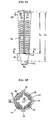
- Each sidewall 14, 16, 18, 20 preferably tapers from a proximal end 10a of the sheath to a distal end 10b of the sheath to form a sheath 10 having a bullet-shaped profile.
- the proximal end 10a of the sheath 10 defines the largest outer diameter or circumference Ds 1 of the sheath
- the distal end 10b defines the smallest outer diameter or circumference Ds 2 of the sheath, as shown in FIG. 3A.
- the sheath 10 also includes an inner diameter x which is the largest at its proximal end 10a and decreases towards its distal end 10b.
- Each sidewall 14, 16, 18, 20 of the sheath 10 is preferably separated from an adjacent sidewall by a longitudinally oriented slot 22, 24, 26, 28 extending therebetween.
- Each slot 22, 24, 26, 28 can have the same length ls, or alternatively the length of each slot 22, 24, 26, 28 can vary with respect to each other.
- each slot 22, 24, 26, 28 has the same length ls and originates at the proximal end 10a of the sheath 10 and extends along a substantial length Ls of the sheath 10 to allow the sidewalls 14, 16, 18, 20 to flex with respect to each other.
- Each slot 22, 24, 26, 28 preferably terminates at the same position P just proximal to the distal end 10b of the sheath to provide a slot-free distal tip 30.
- This termination point P defines the area at which each sidewall 14, 16, 18, 20 will bend during expansion of the sheath 10 by a sheath expander.
- the distance between the termination point P at the end of each slot 22, 24, 26, 28 and the distal end 10b of the sheath should be sufficient to provide structural integrity to the device such that the sidewalls 14, 16, 18, 20 do not break apart from one another or from the distal tip 30 during expansion.
- each sidewall 14, 16, 18, 20 of the sheath 10 can also have a variety of shapes and sizes.
- each sidewall 14, 16, 18, 20 has a substantially concave outer surface that is adapted to seat a graft.
- the concave surface preferably extends along the length ls of each sidewall 14, 16, 18, 20.
- the proximal-most portion of each sidewall 14, 16, 18, 20, however, can include a flared region 32 (FIG. 2) to provide an enlarged opening to the inner lumen 34 to facilitate insertion of a sheath expander therein.
- Each sidewall 14, 16, 18, 20 can also include one or more surface features 36 formed on the concave surface to facilitate engagement of a graft between the sidewalls 14, 16, 18, 20 and the bone tunnel when the sheath 10 is implanted.
- the surface features 36 can have a variety of configurations, and can be formed on all or a portion of one or more of the sidewalls 14, 16, 18, 20. As shown in FIGS. 1-3A, the surface features 36 are formed from a series of transversely-oriented ridges 36 formed along a substantially portion of each sidewall 14, 16, 18, 20. The ridges 36 are effective to engage or grip the graft to prevent sliding movement of the graft with respect to the sheath 10.
- the sheath 10 can include a variety of different features to facilitate engagement between the sheath 10 and the graft.
- Each sidewall 14, 16, 18, 20 can also include one or more longitudinal flexion regions to allow each sidewall 14, 16, 18, 20 to expand radially outward upon insertion of a sheath expander into the lumen 34 of the sheath 10.
- FIG. 2 illustrates flexion regions 38a, 38b on sidewall 16.
- the flexion regions 38a, 38b are formed from substantially parallel edges that extend along the length Ls of the sheath 10 and that define the concave shape of each sidewall 14, 16, 18, 20.
- the flexion regions can optionally be formed by thinning the material that forms each sidewall 14, 16, 18, 20 longitudinally in the region of desired flexion, and in one embodiment, may be one or more longitudinal grooves cut into each sidewall 14, 16, 18, 20.
- the expansion of the sidewalls 14, 16, 18, 20 at the flexion regions 38a, 38b will retain the graft material disposed within the sidewall 14, 16, 18, 20 by an interference fit between the expanded sidewall 14, 16, 18, 20 and the bone tunnel wall.
- FIGS. 1-3B illustrate an exemplary embodiment of a stop member 40 formed on the proximal-most end 10a of the sheath 10 and extending between two adjacent sidewalls, e.g., sidewalls 14 and 20, to connect the sidewalls 14, 20.
- the stop member 40 can have a variety of configurations, and in one embodiment, as shown, is a tab-like protrusion that extends outward from the circumference of the proximal end 10a of the sheath 10. As a result, the stop member 40 will abut the edge of a bone tunnel during insertion of the sheath 10 into the bone tunnel, thereby preventing over-insertion of the sheath 10.
- the stop member 40 can optionally be adapted to break upon insertion of a sheath expander into the sheath 10 to allow the sidewalls 14, 16, 18, 20 to expand.
- the stop member 40 can include a weakened portion (not shown) formed at the desired breakage point.
- the distal tip 30 of the sheath can also have a variety of configurations, shapes and sizes. Since the distal tip 30 connects the four sidewalls 14, 16, 18, 20 to one another to provide structural integrity to the sheath 10, the distal tip 30 is preferably slot-free, and also preferably does not include any surface features 36 formed thereon. While the shape of the distal tip 30 can vary, the distal tip 30 preferably originates adjacent to the termination point P of each longitudinal slot 22, 24, 26, 8, and tapers toward the distal end 10b of the sheath 10.
- the distal tip 30 can optionally include a flattened distal-most surface 42 (FIG. 3A) that joins a distal-most end of each sidewall 14, 16, 18, 20 to one another.
- the edges (not shown) that connect the flattened surface 42 to each sidewall 14, 16, 18, 20 are preferably rounded to form a substantially rounded distal tip 30.
- the distal tip 30 can also optionally include a bore 44 (FIG. 3B) extending through the flattened surface 42 for receiving a guide wire to facilitate implantation of the device.
- a bore 44 FIG. 3B
- the distal tip 30 of the sheath 10 can have virtually any shape and size, and can optionally be substantially open or closed.
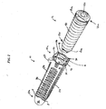
- FIG. 1 illustrates an exemplary embodiment of a sheath expander 12 in the form of a tapered screw.
- the screw 12 includes a proximal end 12a defining the largest diameter ds 1 of the screw, and a distal end 12b defining the smallest diameter ds 2 of the screw 12. Threads 50 are formed around the screw 12 and extend from the proximal end 12a to the distal end 12b.
- the screw 12 is adapted to expand the expandable sheath 10, thus the largest diameter ds 2 of the screw 12 is preferably larger than the largest inner diameter x (FIG. 1) of the sheath 10, and more preferably it is at least as large as the largest outer diameter Ds 1 of the sheath 10.
- the expander screw 12 also preferably includes a socket 52 formed in the proximal end 12a thereof for receiving a driver tool, such as a hex wrench, that is effective to drive the screw 12 into the sheath 10.
- the expander screw 12 can also include a lumen (not shown) extending therethrough for receiving a guide wire to facilitate insertion of the screw 12 into the sheath 10.
- the sheath expander 12 can have a variety of configurations, shapes, and sizes.
- the expandable sheath 10 and sheath expander 12 can be used in a variety of medical procedures, but they are preferably used to anchor ligaments within a bone tunnel.
- the device or system 10, 12 is used for tibial fixation of an anterior cruciate ligament graft.
- a bone tunnel is prepared in the patient's tibia, and the graft is separated into four tendon bundles, each of which is prepared by whip stitching a length of suture thereto.
- the graft is then passed through the tunnel and tensioned as necessary. While tensioning the graft, the expandable sheath 10 is inserted into the opening of the bone tunnel, preferably by sliding the sheath 10 along a guide wire extending through the tunnel.
- a mallet or other impacting device can be used to gently advance the sheath 10 into the tunnel.
- the stop member 40 will abut the opening of the tunnel when the sheath 10 is fully inserted.
- a graft bundle which preferably includes four grafts 56, 58, 60, 62, as shown in FIG. 4A, is preferably seated within each sidewall 14, 16, 18, 20 of the expandable sheath 10.
- the sheath expander e.g., tapered expander screw 12
- the concave sidewalls 14, 16, 18, 20 of the sheath 10 will deform toward a circular geometry to conform with an outer diameter of the expander 12, and thus to compress each tendon bundle 56, 58, 60, 62 against the bone tunnel wall 70, as shown in FIG. 4B. This will encourage rapid bony ingrowth into each bundle.
- the sheath 10 of the present invention provides several advantages over prior art sheaths.
- the longitudinally oriented slots 22, 24, 26, 28 reduce or eliminate the risk of cracking or splitting during expansion. While some prior art sheaths provide a weakened portion adapted to rupture or break upon insertion, the sheath can crack at unintended portions.
- the slots 22, 24, 26, 28 of the sheath 10 of the present invention eliminate the need for the sheath 10 to crack during insertion of the sheath expander 12 therein since the longitudinal slots 22, 24, 26, 28 allow for expansion without cracking.
- the slots 22, 24, 26, 28 also allow the sheath 10 to be formed from a material having a relatively low elasticity, e.g., a brittle material.
- the entire sheath 10 can be made from a brittle material.
- suitable materials include biocompatible, bioabsorbable polymers or copolymers formed of monomers selected from the group consisting of lactic acid, glycolic acid, and caprolactone.
- the material can also include tricalcium phosphate.
- the sheath 10 can also be formed from bioabsorbable glasses and ceramics (possibly containing calcium phosphates and other biocompatible metal oxides (i.e., CaO)).
- the sheath 10 can also be formed from metals, or it can comprise combinations of metals, bioabsorbable ceramics, glasses or polymers.
- the longitudinal slots 22, 24, 26, 28 facilitate the use of expanders 12 having a wider variety of sizes, including the use of expanders 12 having an outer diameter ds 1 or circumference at least as large as the diameter Ds 1 or circumference of sheath 10.
- sheath 10 may be provided in a kit to surgeons in which a plurality of expanders having different sizes are provided for use with a single size sheath.
Landscapes
- Health & Medical Sciences (AREA)
- Orthopedic Medicine & Surgery (AREA)
- Rehabilitation Therapy (AREA)
- Rheumatology (AREA)
- Cardiology (AREA)
- Oral & Maxillofacial Surgery (AREA)
- Transplantation (AREA)
- Engineering & Computer Science (AREA)
- Biomedical Technology (AREA)
- Heart & Thoracic Surgery (AREA)
- Vascular Medicine (AREA)
- Life Sciences & Earth Sciences (AREA)
- Animal Behavior & Ethology (AREA)
- General Health & Medical Sciences (AREA)
- Public Health (AREA)
- Veterinary Medicine (AREA)
- Prostheses (AREA)
- Surgical Instruments (AREA)
Abstract
Description
- The present invention relates to ligament fixation devices and methods, and more particularly to devices and methods for anchoring ligaments within a bone tunnel.
- Ligaments are tough bands of tissue which serve to connect the articular extremities of bones, or to support or retain organs in place within the body. Ligaments are typically composed of coarse bundles of dense white fibrous tissue which are disposed in a parallel or closely interlaced manner, with the fibrous tissue being pliant and flexible, but not significantly extensible.
- In many cases, ligaments are torn or ruptured as a result of accidents or overexertion. Accordingly, various procedures have been developed to repair or replace such damaged ligaments. For example, in the human knee, the anterior and posterior cruciate ligaments (i.e., the ACL and PCL) extend between the top end of the tibia and the bottom end of the femur. The ACL and PCL cooperate, together with other ligaments and soft tissue, to provide both static and dynamic stability to the knee. Often, the ACL is ruptured or torn as a result of, for example, a sports-related injury. Consequently, various surgical procedures have been developed for reconstructing the ACL so as to restore normal function to the knee.
- In many instances, the ACL may be reconstructed by replacing the ruptured ACL with a graft ligament. More particularly, with such procedures, bone tunnels are typically formed in the top end of the tibia and the bottom end of the femur, with one end of the graft ligament being positioned in the femoral tunnel and the other end of the graft ligament being positioned in the tibial tunnel. The two ends of the graft ligament are anchored in place in various ways known in the art so that the graft ligament extends between the femur and the tibia in substantially the same way, and with substantially the same function, as the original ACL. This graft ligament then cooperates with the surrounding anatomical structures so as to restore normal function to the knee.
- Despite the above-identified advances in the art, there remains a need for a graft ligament anchor which is simple, easy to install, and inexpensive to manufacture, while providing secure, trouble-free anchoring of the graft ligament.
- The present invention generally provides a graft fixation device for fixing a graft member within a bone tunnel. In one embodiment, the device includes a bioabsorbable, radially expandable sheath having a substantially closed distal end with at least two sidewalls extending proximally therefrom and defining a central lumen. Each sidewall is at least partially separated by a longitudinally oriented slot extending from a proximal end along a substantial length of each sidewall and terminating at a position proximal to the distal end. The shape of the sidewalls can vary, but preferably each sidewall has a substantially concave outer surface adapted to seat a graft member. Each sidewall can optionally include surface features formed within the concave outer surface thereof. The device can also include a bioabsorbable sheath expander, e.g., a tapered screw, adapted to be disposed in the central lumen of the radially expandable sheath and configured to flex the sidewalls to radially expand the sheath so as to fix a graft member within a bone tunnel. In an exemplary embodiment, the sheath expander has a largest diameter that is greater than a largest inner diameter of the radially expandable sheath in an unexpanded state.
- The radially expandable sheath can have a variety of configurations. In one embodiment, the distal portion of the radially expandable sheath, extending between a distal end of the longitudinally oriented slots and a distal end of the sheath, tapers to form a bullet-shaped distal tip. In another embodiment, at least two adjacent sidewalls are joined at a proximal end thereof by a stop member adapted to prevent over-insertion of the radially expandable sheath into a bone tunnel.
- The configuration of the graft fixation device allows the device to be formed from a variety of materials, including materials having a low elasticity. In an exemplary embodiment, the graft fixation device is formed from one or more polymers or copolymers formed from monomers selected from the group consisting of lactic acid, glycolic acid, and caprolactone. In a more preferred embodiment, the material further includes tricalcium phosphate.
- In yet another embodiment, a graft fixation device for fixing a graft member within a bone tunnel is provided. The device includes a bioabsorbable, radially expandable sheath having a substantially closed distal end with at least two sidewalls extending proximally therefrom and defining a central lumen. Each sidewall has a substantially concave outer surface adapted to seat a graft member, and each side wall is at least partially separated by a longitudinally oriented slot extending from a proximal end along a substantial length of each sidewall and terminating at a position proximal to the distal end.
- In other aspects, a graft fixation kit for fixing a graft member within a bone tunnel is provided. The kit includes a bioabsorbable expandable sheath having proximal and distal ends with at least two sidewalls extending therebetween and defining a central lumen. Each sidewall is at least partially separated by a longitudinally oriented slot extending from the proximal end and terminating at a position just proximal to the distal end, and each sidewall has an outer surface adapted to seat a graft member. The kit further includes a plurality of sheath expanders of varying sizes, each being disposable in the central lumen of the expandable sheath and configured to flex the sidewalls to radially expand the sheath so as to fix at least one graft member within a bone tunnel.
- Methods for fixing a ligament graft in a bone tunnel are also provided.
- These and other objects and features of the present invention will be more fully disclosed or rendered obvious by the following detailed description of the preferred embodiments of the invention, which are to be considered together with the accompanying drawings wherein like numbers refer to like parts, and further wherein:
- FIG. 1 is a perspective view of a radially expandable sheath and a sheath expander in accordance with one embodiment of the invention;
- FIG. 2 is a perspective view of the radially expandable sheath shown in FIG. 1;
- FIG. 3A is a side view of the radially expandable sheath shown in FIGS. 1 and 2;
- FIG. 3B is a cross-sectional view of the radially expandable sheath shown in FIG. 3A taken across
line 3B-3B; - FIG. 4A is an illustration of a bone tunnel having four segments of a ligament graft and a radially expandable sheath disposed therein in an unexpanded position; and
- FIG. 4B is an illustration of the bone tunnel, ligament segments, and radially expandable sheath shown in FIG. 4A with the radially expandable sheath in the expanded position.
- As shown in FIG. 1, the present invention generally provides a radially
expandable sheath 10 for attaching a ligament graft to bone. In general, the expandable sheath has a substantially closed distal end with at least two sidewalls (FIG. 1 illustrates foursidewalls inner lumen 34. Eachsidewall sidewall oriented slot proximal end 10a along a substantial length of eachsidewall slots sheath 10. The device can also optionally include asheath expander 12 that is adapted to be disposed in thecentral lumen 34 of the radiallyexpandable sheath 10 and that is configured to flex thesidewalls sheath 10 so as to fix a graft member within a bone tunnel. - A person skilled in the art will appreciate that a variety of implants having virtually any configuration can be used to expand the expandable sheath, and that sheath expander 12 is merely one embodiment of an implant that can be used with the expandable sheath. Moreover, the
expandable sheath 10 can be used to attach a variety of materials to bone in a variety of medical procedures. Accordingly, the terms "graft" or "ligament graft," as used herein, are intended to include any number of natural and/or synthetic graft and/or tendon materials. - The
expandable sheath 10 can have a variety of configurations, shapes, and sizes, but it should be adapted to expand within a bone tunnel to attach a ligament graft to bone. FIGS. 1-3B illustrate an exemplary embodiment of anexpandable sheath 10 having proximal anddistal ends 10a, 10b with foursidewalls sidewalls sheath 10 can have any number of sidewalls. Thesheath 10 should, however, have at least two sidewalls to allow thesheath 10 to expand upon insertion of a sheath expander therein. Eachsidewall proximal end 10a of the sheath to a distal end 10b of the sheath to form asheath 10 having a bullet-shaped profile. As a result, theproximal end 10a of thesheath 10 defines the largest outer diameter or circumference Ds 1 of the sheath, and the distal end 10b defines the smallest outer diameter or circumference Ds 2 of the sheath, as shown in FIG. 3A. Thesheath 10 also includes an inner diameter x which is the largest at itsproximal end 10a and decreases towards its distal end 10b. - Each
sidewall sheath 10 is preferably separated from an adjacent sidewall by a longitudinally orientedslot slot slot slot proximal end 10a of thesheath 10 and extends along a substantial length Ls of thesheath 10 to allow thesidewalls slot distal tip 30. This termination point P defines the area at which eachsidewall sheath 10 by a sheath expander. Thus, while the termination point P can vary, the distance between the termination point P at the end of eachslot sidewalls distal tip 30 during expansion. - Each
sidewall sheath 10 can also have a variety of shapes and sizes. In an exemplary embodiment, eachsidewall sidewall sidewall inner lumen 34 to facilitate insertion of a sheath expander therein. Eachsidewall sheath 10 is implanted. The surface features 36 can have a variety of configurations, and can be formed on all or a portion of one or more of thesidewalls ridges 36 formed along a substantially portion of eachsidewall ridges 36 are effective to engage or grip the graft to prevent sliding movement of the graft with respect to thesheath 10. A person skilled in the art will appreciate that thesheath 10 can include a variety of different features to facilitate engagement between thesheath 10 and the graft. - Each
sidewall sidewall lumen 34 of thesheath 10. FIG. 2 illustrates flexion regions 38a, 38b onsidewall 16. As shown, the flexion regions 38a, 38b are formed from substantially parallel edges that extend along the length Ls of thesheath 10 and that define the concave shape of eachsidewall sidewall sidewall sidewalls sidewall sidewall - While each
sidewall sheath 10 into a bone tunnel. While the stop member can have a variety of configurations, FIGS. 1-3B illustrate an exemplary embodiment of astop member 40 formed on theproximal-most end 10a of thesheath 10 and extending between two adjacent sidewalls, e.g., sidewalls 14 and 20, to connect thesidewalls stop member 40 can have a variety of configurations, and in one embodiment, as shown, is a tab-like protrusion that extends outward from the circumference of theproximal end 10a of thesheath 10. As a result, thestop member 40 will abut the edge of a bone tunnel during insertion of thesheath 10 into the bone tunnel, thereby preventing over-insertion of thesheath 10. - While the
stop member 40 connects two adjacent sidewalls, thestop member 40 can optionally be adapted to break upon insertion of a sheath expander into thesheath 10 to allow thesidewalls stop member 40 can include a weakened portion (not shown) formed at the desired breakage point. A person skilled in the art will appreciate that a variety of techniques can be used to achieve the desired breakage. - The
distal tip 30 of the sheath can also have a variety of configurations, shapes and sizes. Since thedistal tip 30 connects the foursidewalls sheath 10, thedistal tip 30 is preferably slot-free, and also preferably does not include any surface features 36 formed thereon. While the shape of thedistal tip 30 can vary, thedistal tip 30 preferably originates adjacent to the termination point P of eachlongitudinal slot sheath 10. Thedistal tip 30 can optionally include a flattened distal-most surface 42 (FIG. 3A) that joins a distal-most end of eachsidewall surface 42 to eachsidewall distal tip 30. Thedistal tip 30 can also optionally include a bore 44 (FIG. 3B) extending through the flattenedsurface 42 for receiving a guide wire to facilitate implantation of the device. A person skilled in the art will appreciate that thedistal tip 30 of thesheath 10 can have virtually any shape and size, and can optionally be substantially open or closed. - Referring back to FIG. 1, a
sheath expander 12 can be used to expand theexpandable sheath 10 once thesheath 10 is inserted into a bone tunnel. While thesheath expander 12 can have virtually any configuration, FIG. 1 illustrates an exemplary embodiment of asheath expander 12 in the form of a tapered screw. Thescrew 12 includes aproximal end 12a defining the largest diameter ds 1 of the screw, and a distal end 12b defining the smallest diameter ds 2 of thescrew 12.Threads 50 are formed around thescrew 12 and extend from theproximal end 12a to the distal end 12b. In use, thescrew 12 is adapted to expand theexpandable sheath 10, thus the largest diameter ds 2 of thescrew 12 is preferably larger than the largest inner diameter x (FIG. 1) of thesheath 10, and more preferably it is at least as large as the largest outer diameter Ds 1 of thesheath 10. Theexpander screw 12 also preferably includes asocket 52 formed in theproximal end 12a thereof for receiving a driver tool, such as a hex wrench, that is effective to drive thescrew 12 into thesheath 10. Theexpander screw 12 can also include a lumen (not shown) extending therethrough for receiving a guide wire to facilitate insertion of thescrew 12 into thesheath 10. As previously stated, a person skilled in the art will appreciate thesheath expander 12 can have a variety of configurations, shapes, and sizes. - The
expandable sheath 10 andsheath expander 12 can be used in a variety of medical procedures, but they are preferably used to anchor ligaments within a bone tunnel. In an exemplary embodiment, the device orsystem expandable sheath 10 is inserted into the opening of the bone tunnel, preferably by sliding thesheath 10 along a guide wire extending through the tunnel. A mallet or other impacting device can be used to gently advance thesheath 10 into the tunnel. Thestop member 40 will abut the opening of the tunnel when thesheath 10 is fully inserted. In this position, a graft bundle, which preferably includes fourgrafts 56, 58, 60, 62, as shown in FIG. 4A, is preferably seated within eachsidewall expandable sheath 10. The sheath expander, e.g., taperedexpander screw 12, is then slowly inserted into theinner lumen 34 of thesheath 10, using a driver tool, to expand theconcave sidewalls sheath 10. As thesheath expander 12 is driven into thesheath 10, theconcave sidewalls sheath 10 will deform toward a circular geometry to conform with an outer diameter of theexpander 12, and thus to compress eachtendon bundle 56, 58, 60, 62 against thebone tunnel wall 70, as shown in FIG. 4B. This will encourage rapid bony ingrowth into each bundle. - The
sheath 10 of the present invention provides several advantages over prior art sheaths. In particular, the longitudinally orientedslots slots sheath 10 of the present invention eliminate the need for thesheath 10 to crack during insertion of thesheath expander 12 therein since thelongitudinal slots slots sheath 10 to be formed from a material having a relatively low elasticity, e.g., a brittle material. Since thesheath 10 does not need to be designed to break only at an intended location, theentire sheath 10 can be made from a brittle material. By way of non-limiting example, suitable materials include biocompatible, bioabsorbable polymers or copolymers formed of monomers selected from the group consisting of lactic acid, glycolic acid, and caprolactone. In a further embodiment, the material can also include tricalcium phosphate. Thesheath 10 can also be formed from bioabsorbable glasses and ceramics (possibly containing calcium phosphates and other biocompatible metal oxides (i.e., CaO)). Thesheath 10 can also be formed from metals, or it can comprise combinations of metals, bioabsorbable ceramics, glasses or polymers. In an exemplary embodiment, the sheath is formed from polylactic acid (PLA), tricalcium phosphate (TCP), and optionally polyglycolic acid (PGA), and/or polycaprolactone (PCL). More preferably, the sheath is formed from one of the following materials (all percentages are by volume unless otherwise indicated): - (1) 70% PLA + 30% TCP
- (2) 70% of a PGA/PLA mixture + 30% TCP
- (3) 70% of a PLA/PCL mixture + 30% TCP
- (4) 70% of a PGA/PCL/PLA mixture + 30% TCP
- Further, the
longitudinal slots expanders 12 having a wider variety of sizes, including the use ofexpanders 12 having an outer diameter ds 1 or circumference at least as large as the diameter Ds 1 or circumference ofsheath 10. In this way, a single sheath size may be stocked for a wide variety of procedures and intended bone tunnel sizes. In one embodiment,sheath 10 may be provided in a kit to surgeons in which a plurality of expanders having different sizes are provided for use with a single size sheath. - It is to be understood that the present invention is by no means limited to the particular constructions and methods herein disclosed and/or shown in the drawings, but also comprises any modifications or equivalents within the scope of the claims
Claims (17)
- A graft fixation device for fixing a graft member within a bone tunnel, the device comprising:a bioabsorbable radially expandable sheath having a substantially closed distal end with at least two sidewalls extending proximally therefrom and defining a central lumen, each sidewall having a substantially concave outer surface adapted to seat a graft member, and each side wall being at least partially separated by a longitudinally oriented slot extending from a proximal end along a substantial length of each sidewall and terminating at a position proximal to the distal end; anda bioabsorbable sheath expander adapted to be disposed in the central lumen of the radially expandable sheath and configured to flex the sidewalls to radially expand the sheath so as to fix the graft member within a bone tunnel.
- The graft fixation device of claim 1, wherein a distal portion of the radially expandable sheath extending between a distal end of the longitudinally oriented slots and a distal end of the sheath tapers to form a bullet-shaped distal tip.
- The graft fixation device of claim 1, wherein the sheath expander and a distal-most end of the radially expandable sheath each include a lumen extending therethrough for receiving a guide wire.
- The graft fixation device of claim 2, wherein the sidewalls each include surface features formed within the concave outer surface thereof.
- The graft fixation device of claim 1, wherein at least two adjacent sidewalls are joined at a proximal end thereof by a stop member adapted to prevent over-insertion of the radially expandable sheath into a bone tunnel.
- The graft fixation device of claim 1, wherein the sheath expander is a tapered screw.
- The graft fixation device of claim 6, wherein the sheath expander has a largest diameter that is greater than a largest inner diameter of the radially expandable sheath in an unexpanded state.
- The graft fixation device of claim 1, wherein the device is formed from a material having one or more polymers or copolymers formed of monomers selected from the group consisting of lactic acid, glycolic acid, and caprolactone.
- The graft fixation device of claim 8, wherein the material further comprises tricalcium phosphate.
- A graft fixation device for fixing a graft member within a bone tunnel, the device comprising a bioabsorbable radially expandable sheath having a substantially closed distal end with at least two sidewalls extending proximally therefrom and defining a central lumen, each sidewall having a substantially concave outer surface adapted to seat a graft member, and each side wall being at least partially separated by a longitudinally oriented slot extending from a proximal end along a substantial length of each sidewall and terminating at a position proximal to the distal end.
- A graft fixation kit for fixing a graft member within a bone tunnel, the kit comprising:a bioabsorbable expandable sheath having proximal and distal ends with at least two sidewalls extending therebetween and defining a central lumen, each sidewall being at least partially separated by a longitudinally oriented slot extending from the proximal end and terminating at a position just proximal to the distal end, and each sidewall having an outer surface adapted to seat a graft member; anda plurality of sheath expanders of varying sizes, each being disposable in the central lumen of the expandable sheath and configured to flex the sidewalls to radially expand the sheath so as to fix at least one graft member within a bone tunnel.
- The kit of claim 11, wherein the expandable sheath defines a distal tip that tapers from a distal end of each longitudinally oriented slot to the distal end of the expandable sheath.
- The kit of claim 12, wherein the distal tip of the expandable sheath is rounded.
- The kit of claim 12, wherein the sidewalls of the expandable sheath each include a concave outer surface having surface features formed thereon.
- The kit of claim 11, wherein two adjacent sidewalls of the expandable sheath are joined at a proximal end thereof by a stop member adapted to prevent over-insertion of the expandable sheath into a bone tunnel.
- The kit of claim 11, wherein each sheath expander is a tapered screw.
- The kit of claim 16, wherein the sheath expander has a largest diameter that is greater than a largest inner diameter of the radially expandable sheath in an unexpanded state.
Applications Claiming Priority (2)
| Application Number | Priority Date | Filing Date | Title |
|---|---|---|---|
| US608899 | 2003-06-27 | ||
| US10/608,899 US7309355B2 (en) | 2003-06-27 | 2003-06-27 | Flexible tibial sheath |
Publications (3)
| Publication Number | Publication Date |
|---|---|
| EP1491162A2 true EP1491162A2 (en) | 2004-12-29 |
| EP1491162A3 EP1491162A3 (en) | 2006-06-07 |
| EP1491162B1 EP1491162B1 (en) | 2011-02-23 |
Family
ID=33418736
Family Applications (1)
| Application Number | Title | Priority Date | Filing Date |
|---|---|---|---|
| EP04253805A Expired - Lifetime EP1491162B1 (en) | 2003-06-27 | 2004-06-25 | A graft fixation device |
Country Status (6)
| Country | Link |
|---|---|
| US (8) | US7309355B2 (en) |
| EP (1) | EP1491162B1 (en) |
| JP (1) | JP4717386B2 (en) |
| AU (1) | AU2004202393B2 (en) |
| CA (1) | CA2472659C (en) |
| DE (1) | DE602004031484D1 (en) |
Cited By (19)
| Publication number | Priority date | Publication date | Assignee | Title |
|---|---|---|---|---|
| WO2007109280A2 (en) | 2006-03-20 | 2007-09-27 | Cayenne Medical, Inc | Devices, systems, and methods for material fixation |
| WO2008044080A2 (en) * | 2006-10-12 | 2008-04-17 | George Stefanoudakis | Securing appliance for tendon grafts |
| EP1905385A3 (en) * | 2006-09-29 | 2008-08-20 | DePuy Mitek, Inc. | Femoral fixation |
| WO2011005966A3 (en) * | 2009-07-09 | 2011-03-03 | Smith & Nephew, Inc. | Tissue graft anchor assembly and instrumentation for use therewith |
| WO2011059995A3 (en) * | 2009-11-10 | 2011-07-14 | Smith & Nephew, Inc. | Tissue repair devices |
| CH703627A1 (en) * | 2010-08-25 | 2012-02-29 | Arnold Schefer | Anchor sleeve. |
| EP2486856A3 (en) * | 2011-02-09 | 2013-05-01 | Arthrex, Inc. | Bone anchor for scapholunate construct |
| AU2013200756B2 (en) * | 2006-03-20 | 2014-12-11 | Cayenne Medical, Inc | Devices, systems, and methods for material fixation |
| EP3020369A1 (en) * | 2014-10-23 | 2016-05-18 | DePuy Synthes Products, Inc. | Biceps tenodesis anchor implants |
| US9345467B2 (en) | 2007-10-25 | 2016-05-24 | Smith & Nephew, Inc. | Anchor assembly |
| EP3042632A1 (en) * | 2015-01-12 | 2016-07-13 | Universität Zürich | Device for tendon and ligament reconstruction |
| EP3020370A3 (en) * | 2014-10-23 | 2016-08-31 | DePuy Synthes Products, Inc. | Biceps tenodesis implants and delivery tools |
| US10117739B2 (en) | 2006-10-24 | 2018-11-06 | Cayenne Medical, Inc. | Methods and systems for material fixation |
| US10709488B2 (en) | 2014-10-23 | 2020-07-14 | Medos International Sárl | Biceps tenodesis delivery tools |
| US10729419B2 (en) | 2014-10-23 | 2020-08-04 | Medos International Sarl | Biceps tenodesis implants and delivery tools |
| US10758337B2 (en) | 2015-04-22 | 2020-09-01 | Medos International Sarl | Biceps repair device |
| US10869751B2 (en) | 2014-10-23 | 2020-12-22 | Medos International Sarl | Biceps tenodesis implants and delivery tools |
| US11065104B2 (en) | 2016-04-08 | 2021-07-20 | Medos International Sarl | Tenodesis anchoring systems and tools |
| US11071621B2 (en) | 2016-04-08 | 2021-07-27 | Medos International Sarl | Tenodesis implants and tools |
Families Citing this family (162)
| Publication number | Priority date | Publication date | Assignee | Title |
|---|---|---|---|---|
| US7083647B1 (en) | 1996-11-27 | 2006-08-01 | Sklar Joseph H | Fixation screw, graft ligament anchor assembly, and method for securing a graft ligament in a bone tunnel |
| US6554862B2 (en) * | 1996-11-27 | 2003-04-29 | Ethicon, Inc. | Graft ligament anchor and method for attaching a graft ligament to a bone |
| US5899938A (en) | 1996-11-27 | 1999-05-04 | Joseph H. Sklar | Graft ligament anchor and method for attaching a graft ligament to a bone |
| US6497726B1 (en) | 2000-01-11 | 2002-12-24 | Regeneration Technologies, Inc. | Materials and methods for improved bone tendon bone transplantation |
| US20030023304A1 (en) * | 2000-01-11 | 2003-01-30 | Carter Kevin C. | Materials and methods for improved bone tendon bone transplantation |
| US7235079B2 (en) * | 2004-11-18 | 2007-06-26 | Acumed Llc | Composite bone fasteners |
| US6887271B2 (en) | 2001-09-28 | 2005-05-03 | Ethicon, Inc. | Expanding ligament graft fixation system and method |
| US7309355B2 (en) * | 2003-06-27 | 2007-12-18 | Depuy Mitek, Inc. | Flexible tibial sheath |
| US7326247B2 (en) * | 2003-10-30 | 2008-02-05 | Arthrex, Inc. | Method for creating a double bundle ligament orientation in a single bone tunnel during knee ligament reconstruction |
| WO2006023661A2 (en) * | 2004-08-18 | 2006-03-02 | Scandius Biomedical, Inc. | Method and apparatus for reconstructing a ligament |
| US7468074B2 (en) * | 2004-10-29 | 2008-12-23 | Arthrex, Inc. | Ligament fixation using graft harness |
| US9801708B2 (en) | 2004-11-05 | 2017-10-31 | Biomet Sports Medicine, Llc | Method and apparatus for coupling soft tissue to a bone |
| US7749250B2 (en) | 2006-02-03 | 2010-07-06 | Biomet Sports Medicine, Llc | Soft tissue repair assembly and associated method |
| US9017381B2 (en) | 2007-04-10 | 2015-04-28 | Biomet Sports Medicine, Llc | Adjustable knotless loops |
| US8840645B2 (en) | 2004-11-05 | 2014-09-23 | Biomet Sports Medicine, Llc | Method and apparatus for coupling soft tissue to a bone |
| US7905904B2 (en) | 2006-02-03 | 2011-03-15 | Biomet Sports Medicine, Llc | Soft tissue repair device and associated methods |
| US8298262B2 (en) | 2006-02-03 | 2012-10-30 | Biomet Sports Medicine, Llc | Method for tissue fixation |
| US8088130B2 (en) | 2006-02-03 | 2012-01-03 | Biomet Sports Medicine, Llc | Method and apparatus for coupling soft tissue to a bone |
| US8128658B2 (en) | 2004-11-05 | 2012-03-06 | Biomet Sports Medicine, Llc | Method and apparatus for coupling soft tissue to bone |
| US8118836B2 (en) | 2004-11-05 | 2012-02-21 | Biomet Sports Medicine, Llc | Method and apparatus for coupling soft tissue to a bone |
| US8137382B2 (en) | 2004-11-05 | 2012-03-20 | Biomet Sports Medicine, Llc | Method and apparatus for coupling anatomical features |
| US7909851B2 (en) | 2006-02-03 | 2011-03-22 | Biomet Sports Medicine, Llc | Soft tissue repair device and associated methods |
| US8361113B2 (en) | 2006-02-03 | 2013-01-29 | Biomet Sports Medicine, Llc | Method and apparatus for coupling soft tissue to a bone |
| US7601165B2 (en) | 2006-09-29 | 2009-10-13 | Biomet Sports Medicine, Llc | Method and apparatus for forming a self-locking adjustable suture loop |
| US8303604B2 (en) | 2004-11-05 | 2012-11-06 | Biomet Sports Medicine, Llc | Soft tissue repair device and method |
| US8998949B2 (en) | 2004-11-09 | 2015-04-07 | Biomet Sports Medicine, Llc | Soft tissue conduit device |
| US7651528B2 (en) | 2004-11-18 | 2010-01-26 | Cayenne Medical, Inc. | Devices, systems and methods for material fixation |
| WO2006108114A2 (en) | 2005-04-01 | 2006-10-12 | The Regents Of The University Of Colorado | A graft fixation device and method |
| US7655043B2 (en) * | 2005-04-29 | 2010-02-02 | Warsaw Orthopedic, Inc. | Expandable spinal implant and associated instrumentation |
| US8652172B2 (en) | 2006-02-03 | 2014-02-18 | Biomet Sports Medicine, Llc | Flexible anchors for tissue fixation |
| US9468433B2 (en) | 2006-02-03 | 2016-10-18 | Biomet Sports Medicine, Llc | Method and apparatus for forming a self-locking adjustable loop |
| US8506597B2 (en) | 2011-10-25 | 2013-08-13 | Biomet Sports Medicine, Llc | Method and apparatus for interosseous membrane reconstruction |
| US11311287B2 (en) | 2006-02-03 | 2022-04-26 | Biomet Sports Medicine, Llc | Method for tissue fixation |
| US8597327B2 (en) | 2006-02-03 | 2013-12-03 | Biomet Manufacturing, Llc | Method and apparatus for sternal closure |
| US9149267B2 (en) | 2006-02-03 | 2015-10-06 | Biomet Sports Medicine, Llc | Method and apparatus for coupling soft tissue to a bone |
| US8652171B2 (en) | 2006-02-03 | 2014-02-18 | Biomet Sports Medicine, Llc | Method and apparatus for soft tissue fixation |
| US8251998B2 (en) | 2006-08-16 | 2012-08-28 | Biomet Sports Medicine, Llc | Chondral defect repair |
| US8562647B2 (en) | 2006-09-29 | 2013-10-22 | Biomet Sports Medicine, Llc | Method and apparatus for securing soft tissue to bone |
| US9078644B2 (en) | 2006-09-29 | 2015-07-14 | Biomet Sports Medicine, Llc | Fracture fixation device |
| US8968364B2 (en) | 2006-02-03 | 2015-03-03 | Biomet Sports Medicine, Llc | Method and apparatus for fixation of an ACL graft |
| US9538998B2 (en) | 2006-02-03 | 2017-01-10 | Biomet Sports Medicine, Llc | Method and apparatus for fracture fixation |
| US8574235B2 (en) | 2006-02-03 | 2013-11-05 | Biomet Sports Medicine, Llc | Method for trochanteric reattachment |
| US8562645B2 (en) | 2006-09-29 | 2013-10-22 | Biomet Sports Medicine, Llc | Method and apparatus for forming a self-locking adjustable loop |
| US10517587B2 (en) | 2006-02-03 | 2019-12-31 | Biomet Sports Medicine, Llc | Method and apparatus for forming a self-locking adjustable loop |
| US11259792B2 (en) | 2006-02-03 | 2022-03-01 | Biomet Sports Medicine, Llc | Method and apparatus for coupling anatomical features |
| US8771352B2 (en) | 2011-05-17 | 2014-07-08 | Biomet Sports Medicine, Llc | Method and apparatus for tibial fixation of an ACL graft |
| US8801783B2 (en) * | 2006-09-29 | 2014-08-12 | Biomet Sports Medicine, Llc | Prosthetic ligament system for knee joint |
| DE102006010116A1 (en) * | 2006-02-27 | 2007-08-30 | Karl Storz Gmbh & Co.Kg | Anchor element for knot-free fixation of tissue to a bone |
| EP1836996A1 (en) * | 2006-03-20 | 2007-09-26 | Inion Oy | Implant for securing a flexible piece to bone |
| US20070225805A1 (en) * | 2006-03-21 | 2007-09-27 | Reinhold Schmieding | Ligament Fixation Using Graft Harness/Bolt Assembly |
| US8500818B2 (en) | 2006-09-29 | 2013-08-06 | Biomet Manufacturing, Llc | Knee prosthesis assembly with ligament link |
| US11259794B2 (en) | 2006-09-29 | 2022-03-01 | Biomet Sports Medicine, Llc | Method for implanting soft tissue |
| US8672969B2 (en) | 2006-09-29 | 2014-03-18 | Biomet Sports Medicine, Llc | Fracture fixation device |
| US9918826B2 (en) | 2006-09-29 | 2018-03-20 | Biomet Sports Medicine, Llc | Scaffold for spring ligament repair |
| US7963983B2 (en) | 2006-10-17 | 2011-06-21 | Arthroscopic Innovations Llc | Fixation device for surgical repair |
| US8617185B2 (en) | 2007-02-13 | 2013-12-31 | P Tech, Llc. | Fixation device |
| GB0710023D0 (en) * | 2007-05-25 | 2007-07-04 | Facilities Council | Graft fixation device |
| US8021396B2 (en) | 2007-06-05 | 2011-09-20 | Spartek Medical, Inc. | Configurable dynamic spinal rod and method for dynamic stabilization of the spine |
| US8092501B2 (en) | 2007-06-05 | 2012-01-10 | Spartek Medical, Inc. | Dynamic spinal rod and method for dynamic stabilization of the spine |
| US8083772B2 (en) | 2007-06-05 | 2011-12-27 | Spartek Medical, Inc. | Dynamic spinal rod assembly and method for dynamic stabilization of the spine |
| US8298267B2 (en) | 2007-06-05 | 2012-10-30 | Spartek Medical, Inc. | Spine implant with a deflection rod system including a deflection limiting shield associated with a bone screw and method |
| US8080039B2 (en) | 2007-06-05 | 2011-12-20 | Spartek Medical, Inc. | Anchor system for a spine implantation system that can move about three axes |
| US8048115B2 (en) | 2007-06-05 | 2011-11-01 | Spartek Medical, Inc. | Surgical tool and method for implantation of a dynamic bone anchor |
| US8114134B2 (en) | 2007-06-05 | 2012-02-14 | Spartek Medical, Inc. | Spinal prosthesis having a three bar linkage for motion preservation and dynamic stabilization of the spine |
| US8057514B2 (en) * | 2007-06-05 | 2011-11-15 | Spartek Medical, Inc. | Deflection rod system dimensioned for deflection to a load characteristic for dynamic stabilization and motion preservation spinal implantation system and method |
| US8267979B2 (en) | 2008-02-26 | 2012-09-18 | Spartek Medical, Inc. | Load-sharing bone anchor having a deflectable post and axial spring and method for dynamic stabilization of the spine |
| US8007518B2 (en) | 2008-02-26 | 2011-08-30 | Spartek Medical, Inc. | Load-sharing component having a deflectable post and method for dynamic stabilization of the spine |
| US8337536B2 (en) | 2008-02-26 | 2012-12-25 | Spartek Medical, Inc. | Load-sharing bone anchor having a deflectable post with a compliant ring and method for stabilization of the spine |
| US8057517B2 (en) | 2008-02-26 | 2011-11-15 | Spartek Medical, Inc. | Load-sharing component having a deflectable post and centering spring and method for dynamic stabilization of the spine |
| US8016861B2 (en) | 2008-02-26 | 2011-09-13 | Spartek Medical, Inc. | Versatile polyaxial connector assembly and method for dynamic stabilization of the spine |
| US8083775B2 (en) | 2008-02-26 | 2011-12-27 | Spartek Medical, Inc. | Load-sharing bone anchor having a natural center of rotation and method for dynamic stabilization of the spine |
| US8097024B2 (en) | 2008-02-26 | 2012-01-17 | Spartek Medical, Inc. | Load-sharing bone anchor having a deflectable post and method for stabilization of the spine |
| US8333792B2 (en) | 2008-02-26 | 2012-12-18 | Spartek Medical, Inc. | Load-sharing bone anchor having a deflectable post and method for dynamic stabilization of the spine |
| US8211155B2 (en) | 2008-02-26 | 2012-07-03 | Spartek Medical, Inc. | Load-sharing bone anchor having a durable compliant member and method for dynamic stabilization of the spine |
| WO2009132341A1 (en) * | 2008-04-25 | 2009-10-29 | The University Of Vermont And State Agricultural College | Fixation device and method for soft tissue grafts |
| US20090281581A1 (en) | 2008-05-06 | 2009-11-12 | Berg Jeffery H | Method and device for securing sutures to bones |
| US8858565B1 (en) | 2008-05-08 | 2014-10-14 | Cayenne Medical, Inc. | Inserter for soft tissue or bone-to-bone fixation device and methods |
| US8123806B1 (en) | 2008-05-09 | 2012-02-28 | Cayenne Medical, Inc | Method of tensioning a tissue graft having suture bundles using a cleated bar |
| WO2009155577A2 (en) * | 2008-06-19 | 2009-12-23 | Synthes Usa, Llc | Bone screw purchase augmentation implants, systems and techniques |
| AU2009270960B2 (en) | 2008-07-17 | 2015-09-03 | Smith & Nephew, Inc. | Surgical devices |
| WO2010088561A2 (en) | 2009-01-30 | 2010-08-05 | Kfx Medical Corporation | System and method for attaching soft tissue to bone |
| US8206446B1 (en) | 2009-03-10 | 2012-06-26 | Cayenne Medical, Inc. | Method for surgically repairing a damaged ligament |
| CA2757296C (en) * | 2009-03-31 | 2016-01-19 | Medicinelodge, Inc. | Double bundle acl repair |
| US8535377B2 (en) * | 2009-03-31 | 2013-09-17 | Imds Corporation | Double bundle ACL repair system |
| US8845725B2 (en) * | 2009-04-17 | 2014-09-30 | Lumaca Orthopaedics Pty Ltd | Tenodesis system |
| US9339370B2 (en) | 2009-04-22 | 2016-05-17 | The Cleveland Clinic Foundation | Apparatus and method for sequentially anchoring multiple graft ligaments in a bone tunnel |
| WO2010124088A1 (en) * | 2009-04-22 | 2010-10-28 | The Cleveland Clinic Foundation | Apparatus and method for sequentially anchoring multiple graft ligaments in a bone tunnel |
| US8343227B2 (en) | 2009-05-28 | 2013-01-01 | Biomet Manufacturing Corp. | Knee prosthesis assembly with ligament link |
| US9364276B2 (en) | 2009-07-09 | 2016-06-14 | Smith & Nephew, Inc | Tissue graft anchor assembly and instrumentation for use therewith |
| WO2011046982A1 (en) | 2009-10-13 | 2011-04-21 | Kfx Medical Corporation | System and method for securing tissue to bone |
| US8613756B2 (en) | 2009-10-30 | 2013-12-24 | Depuy Mitek, Llc | Knotless suture anchor |
| CN102695465A (en) | 2009-12-02 | 2012-09-26 | 斯帕泰克医疗股份有限公司 | Low profile spinal prosthesis incorporating a bone anchor having a deflectable post and a compound spinal rod |
| JP5767249B2 (en) | 2010-01-27 | 2015-08-19 | スポートウェルディング・ゲゼルシャフト・ミット・ベシュレンクテル・ハフツングSportwelding Gmbh | System for fixing tissue or corresponding prosthetic element in a hole in a human or animal bone |
| US20110307015A1 (en) | 2010-06-10 | 2011-12-15 | Spartek Medical, Inc. | Adaptive spinal rod and methods for stabilization of the spine |
| US9044313B2 (en) | 2010-10-08 | 2015-06-02 | Kfx Medical Corporation | System and method for securing tissue to bone |
| EP2661241B1 (en) * | 2011-01-05 | 2016-09-14 | Milux Holding SA | Knee joint device |
| US9358122B2 (en) | 2011-01-07 | 2016-06-07 | K2M, Inc. | Interbody spacer |
| US9427493B2 (en) | 2011-03-07 | 2016-08-30 | The Regents Of The University Of Colorado | Shape memory polymer intraocular lenses |
| EP3412223B1 (en) | 2011-04-13 | 2021-04-07 | ConMed Corporation | System for securing tissue to bone |
| CN103702629B (en) * | 2011-07-18 | 2018-02-27 | 斯博特威尔丁股份有限公司 | Method soft tissue graft thing being fastened in the hole on people's bone or Animal Bone and the retention mechanism suitable for this method |
| US9775597B2 (en) | 2011-10-04 | 2017-10-03 | Conmed Corporation | Dual expansion anchor |
| US8968402B2 (en) | 2011-10-18 | 2015-03-03 | Arthrocare Corporation | ACL implants, instruments, and methods |
| US9357991B2 (en) | 2011-11-03 | 2016-06-07 | Biomet Sports Medicine, Llc | Method and apparatus for stitching tendons |
| US9357992B2 (en) | 2011-11-10 | 2016-06-07 | Biomet Sports Medicine, Llc | Method for coupling soft tissue to a bone |
| US9370350B2 (en) | 2011-11-10 | 2016-06-21 | Biomet Sports Medicine, Llc | Apparatus for coupling soft tissue to a bone |
| US9381013B2 (en) | 2011-11-10 | 2016-07-05 | Biomet Sports Medicine, Llc | Method for coupling soft tissue to a bone |
| CN103211643A (en) * | 2012-01-18 | 2013-07-24 | 北京市春立正达医疗器械股份有限公司 | Anchor kit for fixing ligament |
| US8430916B1 (en) | 2012-02-07 | 2013-04-30 | Spartek Medical, Inc. | Spinal rod connectors, methods of use, and spinal prosthesis incorporating spinal rod connectors |
| WO2014089273A1 (en) * | 2012-12-06 | 2014-06-12 | Indian Wells Medical, Inc. | Steerable guidewire and method of use |
| KR20150017342A (en) | 2012-05-07 | 2015-02-16 | 스미스 앤드 네퓨, 인크. | Compaction pliers having removable cutting inserts |
| EP2910210B1 (en) | 2012-06-18 | 2018-03-07 | Biedermann Technologies GmbH & Co. KG | Bone anchor |
| US9265613B2 (en) | 2012-09-24 | 2016-02-23 | Russell Nevins | Cementless tibial implant |
| WO2014134328A1 (en) * | 2013-02-27 | 2014-09-04 | Coorstek Medical Llc D/B/A Imds | Graft fixation |
| US9757119B2 (en) | 2013-03-08 | 2017-09-12 | Biomet Sports Medicine, Llc | Visual aid for identifying suture limbs arthroscopically |
| US9913637B2 (en) | 2013-03-13 | 2018-03-13 | DePuy Synthes Products, Inc. | Soft tissue fixation system |
| US9901333B2 (en) * | 2013-03-13 | 2018-02-27 | DePuy Synthes Products, Inc. | Soft tissue fixation system |
| EP2967552B8 (en) | 2013-03-14 | 2023-08-30 | ConMed Corporation | Tissue capturing bone anchor |
| US9918827B2 (en) | 2013-03-14 | 2018-03-20 | Biomet Sports Medicine, Llc | Scaffold for spring ligament repair |
| US9585695B2 (en) | 2013-03-15 | 2017-03-07 | Woven Orthopedic Technologies, Llc | Surgical screw hole liner devices and related methods |
| EP2967551B1 (en) | 2013-03-15 | 2018-05-23 | ConMed Corporation | System for securing tissue to bone |
| KR101599603B1 (en) | 2013-08-26 | 2016-03-03 | 경북대학교 산학협력단 | Medical inserting apparatus |
| US10136886B2 (en) | 2013-12-20 | 2018-11-27 | Biomet Sports Medicine, Llc | Knotless soft tissue devices and techniques |
| WO2015157663A1 (en) * | 2014-04-10 | 2015-10-15 | Bowen Mark K | Locking device and method of use |
| WO2015184051A1 (en) | 2014-05-28 | 2015-12-03 | Chappuis James L | Internal pedicle insulator |
| US9615822B2 (en) | 2014-05-30 | 2017-04-11 | Biomet Sports Medicine, Llc | Insertion tools and method for soft anchor |
| US9700291B2 (en) | 2014-06-03 | 2017-07-11 | Biomet Sports Medicine, Llc | Capsule retractor |
| US8956394B1 (en) | 2014-08-05 | 2015-02-17 | Woven Orthopedic Technologies, Llc | Woven retention devices, systems and methods |
| US9907593B2 (en) | 2014-08-05 | 2018-03-06 | Woven Orthopedic Technologies, Llc | Woven retention devices, systems and methods |
| US10039543B2 (en) | 2014-08-22 | 2018-08-07 | Biomet Sports Medicine, Llc | Non-sliding soft anchor |
| JP6408966B2 (en) * | 2014-08-29 | 2018-10-17 | 帝人メディカルテクノロジー株式会社 | Ligament fixture |
| US9993266B2 (en) | 2014-09-13 | 2018-06-12 | Indian Wells Medical, Inc. | Steerable endoluminal punch |
| WO2016044471A1 (en) * | 2014-09-16 | 2016-03-24 | Woven Orthopedic Technologies, Llc | Woven retention devices, systems, packaging, and related methods |
| US9943351B2 (en) | 2014-09-16 | 2018-04-17 | Woven Orthopedic Technologies, Llc | Woven retention devices, systems, packaging, and related methods |
| USD740427S1 (en) | 2014-10-17 | 2015-10-06 | Woven Orthopedic Technologies, Llc | Orthopedic woven retention device |
| KR101639887B1 (en) | 2014-11-11 | 2016-07-14 | 경북대학교 산학협력단 | A system for fixing cervical vertebrae and a driver used for an appratus for fixing cervical vertebrae |
| KR101608949B1 (en) | 2014-11-19 | 2016-04-04 | 경북대학교 산학협력단 | A system for fixing cervical vertebrae, an appratus for fixing cervical vertebrae and a driver used for an appratus for fixing cervical vertebrae |
| US9955980B2 (en) | 2015-02-24 | 2018-05-01 | Biomet Sports Medicine, Llc | Anatomic soft tissue repair |
| EP3267912A4 (en) * | 2015-03-12 | 2019-01-16 | Spinal Balance, Inc. | Pedicle reconstruction device |
| US9974534B2 (en) | 2015-03-31 | 2018-05-22 | Biomet Sports Medicine, Llc | Suture anchor with soft anchor of electrospun fibers |
| WO2016168045A1 (en) | 2015-04-16 | 2016-10-20 | Smith & Nephew, Inc. | Fixation device and tissue fixation method for acl reconstruction |
| CN104905859B (en) * | 2015-07-01 | 2017-11-24 | 上海凯利泰医疗科技股份有限公司 | For the fixing device of Cruciate ligament reconstruction, fixing means and application method |
| KR101670768B1 (en) * | 2015-07-16 | 2016-10-31 | 경북대학교 산학협력단 | Screw anchor assembly |
| US20180221059A1 (en) | 2015-08-05 | 2018-08-09 | Woven Orthopedic Technologies, Llc | Tapping devices, systems and methods for use in bone tissue |
| US10130395B2 (en) * | 2015-08-17 | 2018-11-20 | Globus Medical, Inc. | Modular uniplanar pedicle screw assembly for use with a polyaxial bone fastener |
| WO2017035563A1 (en) * | 2015-09-02 | 2017-03-09 | Maxm Medical Pty Ltd | A tibial anchor arrangement for a short surgical graft used in anterior cruciate ligament knee joint reconstruction |
| US10874445B2 (en) * | 2015-10-13 | 2020-12-29 | Kyungpook National University Industry-Academic Cooperation Foundation | Screw fixing apparatus |
| US9924935B2 (en) | 2015-10-23 | 2018-03-27 | Smith & Nephew, Inc. | Suture anchor assembly with slip fit tip |
| KR101712610B1 (en) | 2015-12-29 | 2017-03-06 | 경북대학교 산학협력단 | A rod connecter |
| US10117698B2 (en) * | 2016-03-01 | 2018-11-06 | Medos International Sarl | Devices, systems, and methods for driving an anchor into bone |
| US10786655B2 (en) | 2016-03-14 | 2020-09-29 | Indian Wells Medical, Inc. | Steerable guidewire and method of use |
| WO2017171152A1 (en) * | 2016-03-30 | 2017-10-05 | (주)서한케어 | Graft fixing implant |
| KR101791004B1 (en) | 2016-06-08 | 2017-10-27 | 경북대학교 산학협력단 | Screw anchor assembly and a method for using the same to pedicle screw instrumentation |
| US10265157B2 (en) | 2016-06-30 | 2019-04-23 | Medos International Sarl | Methods and devices for tensioning grafts |
| CA2975548A1 (en) | 2016-08-04 | 2018-02-04 | Stryker Corporation | Instrumentation for soft tissue reconstruction |
| US10624734B2 (en) | 2016-10-18 | 2020-04-21 | Arthrex, Inc. | Surgical assembly for tissue repair |
| EP3551105A4 (en) | 2016-12-09 | 2020-07-29 | Woven Orthopedic Technologies, LLC | Retention devices, lattices and related systems and methods |
| CN106798599A (en) * | 2017-01-06 | 2017-06-06 | 南京市六合区人民医院 | The fixation kit that cruciate ligaments of knee joint is rebuild |
| US11006939B2 (en) | 2017-12-08 | 2021-05-18 | Tendyne Holdings, Inc. | Introducer sheath with seal and methods of using the same |
| CN108371568B (en) * | 2018-03-12 | 2024-08-02 | 长春圣博玛生物材料有限公司 | Knee joint cruciate ligament rebuilds fixing device |
| US11160546B2 (en) | 2019-07-11 | 2021-11-02 | Arthrex, Inc. | Expanding implant and method of tissue fixation |
| US11540920B2 (en) * | 2019-10-17 | 2023-01-03 | Chap-Med, Inc. | Internal pedicle insulator |
| US11648025B1 (en) | 2021-07-30 | 2023-05-16 | Indian Wells Medical, Inc. | Steerable endoluminal punch with introducer and guidewire |
Citations (5)
| Publication number | Priority date | Publication date | Assignee | Title |
|---|---|---|---|---|
| US20020007182A1 (en) * | 1998-08-19 | 2002-01-17 | Kim Andrew C. | Anterior cruciate ligament reconstruction hamstring tendon fixation system |
| WO2002032345A2 (en) * | 2000-10-17 | 2002-04-25 | Coapt Systems, Inc. | Intraosseous soft tissue-to-bone anchor |
| US20020165546A1 (en) * | 2001-04-18 | 2002-11-07 | Goble E. Marlowe | Apparatus and method for attaching a graft ligament to a bone |
| EP1297799A2 (en) * | 2001-09-28 | 2003-04-02 | Ethicon, Inc. | Graft ligament anchor |
| US20030065390A1 (en) * | 2001-09-28 | 2003-04-03 | Justin Daniel F. | Expanding ligament graft fixation system and method |
Family Cites Families (23)
| Publication number | Priority date | Publication date | Assignee | Title |
|---|---|---|---|---|
| US3600765A (en) * | 1968-12-27 | 1971-08-24 | American Chain & Cable Co | Rope end coupling |
| DE2250501C3 (en) * | 1972-10-14 | 1975-04-30 | Artur 7241 Tumlingen Fischer | Fixing means for the socket of a hip joint prosthesis |
| DE3120809A1 (en) * | 1981-05-25 | 1982-12-16 | Hilti AG, 9494 Schaan | ANCHOR BOLT WITH CYLINDRICAL BOLT BODY |
| GB8508710D0 (en) * | 1985-04-03 | 1985-05-09 | Himoud H | Screw for surgical use |
| US4708132A (en) * | 1986-01-24 | 1987-11-24 | Pfizer-Hospital Products Group, Inc. | Fixation device for a ligament or tendon prosthesis |
| GB2211261B (en) * | 1987-10-19 | 1991-03-27 | Nifco Inc | Coupler for coupling together plates |
| US5137395A (en) * | 1989-08-02 | 1992-08-11 | Ingersoll-Rand Company | Dynamic earth anchor, and a sleeve therefor |
| JPH05300917A (en) | 1991-09-20 | 1993-11-16 | Yoshiomi Kuriwaka | End fixture of ligament or the like |
| US5632748A (en) | 1993-06-14 | 1997-05-27 | Linvatec Corporation | Endosteal anchoring device for urging a ligament against a bone surface |
| US5746745A (en) * | 1993-08-23 | 1998-05-05 | Boston Scientific Corporation | Balloon catheter |
| FR2725615B1 (en) | 1994-10-17 | 1997-06-13 | Caffiniere Jean Yves De | BONE ANCHORING DEVICE FOR FIXATION THREADS USED IN ORTHOPEDIC SURGERY |
| US5899938A (en) * | 1996-11-27 | 1999-05-04 | Joseph H. Sklar | Graft ligament anchor and method for attaching a graft ligament to a bone |
| US6533816B2 (en) | 1999-02-09 | 2003-03-18 | Joseph H. Sklar | Graft ligament anchor and method for attaching a graft ligament to a bone |
| US5707395A (en) * | 1997-01-16 | 1998-01-13 | Li Medical Technologies, Inc. | Surgical fastener and method and apparatus for ligament repair |
| US5906632A (en) * | 1997-10-03 | 1999-05-25 | Innovasive Devices, Inc. | Intratunnel attachment device and system for a flexible load-bearing structure and method of use |
| US6099530A (en) * | 1998-04-09 | 2000-08-08 | Smith & Nephew, Inc. | Soft-tissue intra-tunnel fixation device |
| FR2777442B1 (en) * | 1998-04-21 | 2000-07-28 | Tornier Sa | REVERSIBLE EXPANSION SUTURE ANCHOR |
| GB9915550D0 (en) * | 1999-07-03 | 1999-09-01 | Atlantech Medical Devices Limi | A bone anchor |
| DE19939416A1 (en) | 1999-08-20 | 2001-02-22 | Basf Ag | Production of zeolite, e.g. titanium zeolite, useful as catalyst (support), sorbent, pigment or filler for plastics, involves crystallizing solid from precursor(s) and direct drying of reaction mixture |
| DE59901090D1 (en) * | 1999-12-23 | 2002-05-02 | Storz Karl Gmbh & Co Kg | Decentralized drive screw |
| US6746483B1 (en) * | 2000-03-16 | 2004-06-08 | Smith & Nephew, Inc. | Sheaths for implantable fixation devices |
| JP4386564B2 (en) * | 2000-11-30 | 2009-12-16 | 日東電工株式会社 | Method of removing low molecular weight material from polyimide precursor or polyimide containing low molecular weight material |
| US7309355B2 (en) | 2003-06-27 | 2007-12-18 | Depuy Mitek, Inc. | Flexible tibial sheath |
-
2003
- 2003-06-27 US US10/608,899 patent/US7309355B2/en not_active Expired - Lifetime
-
2004
- 2004-05-31 AU AU2004202393A patent/AU2004202393B2/en not_active Ceased
- 2004-06-25 DE DE602004031484T patent/DE602004031484D1/en not_active Expired - Lifetime
- 2004-06-25 JP JP2004188326A patent/JP4717386B2/en not_active Expired - Lifetime
- 2004-06-25 EP EP04253805A patent/EP1491162B1/en not_active Expired - Lifetime
- 2004-06-28 CA CA002472659A patent/CA2472659C/en not_active Expired - Fee Related
-
2007
- 2007-11-06 US US11/935,653 patent/US7699893B2/en not_active Expired - Lifetime
-
2008
- 2008-02-05 US US12/025,927 patent/US8435293B2/en active Active
-
2010
- 2010-03-03 US US12/716,843 patent/US8317863B2/en not_active Expired - Lifetime
-
2013
- 2013-03-07 US US13/788,872 patent/US8956410B2/en not_active Expired - Lifetime
-
2015
- 2015-01-09 US US14/593,080 patent/US9486307B2/en not_active Expired - Lifetime
-
2016
- 2016-10-26 US US15/334,865 patent/US10278807B2/en not_active Expired - Lifetime
-
2019
- 2019-03-27 US US16/366,524 patent/US11039916B2/en not_active Expired - Lifetime
Patent Citations (5)
| Publication number | Priority date | Publication date | Assignee | Title |
|---|---|---|---|---|
| US20020007182A1 (en) * | 1998-08-19 | 2002-01-17 | Kim Andrew C. | Anterior cruciate ligament reconstruction hamstring tendon fixation system |
| WO2002032345A2 (en) * | 2000-10-17 | 2002-04-25 | Coapt Systems, Inc. | Intraosseous soft tissue-to-bone anchor |
| US20020165546A1 (en) * | 2001-04-18 | 2002-11-07 | Goble E. Marlowe | Apparatus and method for attaching a graft ligament to a bone |
| EP1297799A2 (en) * | 2001-09-28 | 2003-04-02 | Ethicon, Inc. | Graft ligament anchor |
| US20030065390A1 (en) * | 2001-09-28 | 2003-04-03 | Justin Daniel F. | Expanding ligament graft fixation system and method |
Cited By (45)
| Publication number | Priority date | Publication date | Assignee | Title |
|---|---|---|---|---|
| WO2007109280A2 (en) | 2006-03-20 | 2007-09-27 | Cayenne Medical, Inc | Devices, systems, and methods for material fixation |
| AU2013200756B2 (en) * | 2006-03-20 | 2014-12-11 | Cayenne Medical, Inc | Devices, systems, and methods for material fixation |
| AU2007227318B2 (en) * | 2006-03-20 | 2013-02-14 | Cayenne Medical, Inc | Devices, systems, and methods for material fixation |
| EP2001405A4 (en) * | 2006-03-20 | 2012-03-21 | Cayenne Medical Inc | Devices, systems, and methods for material fixation |
| EP2001405A2 (en) * | 2006-03-20 | 2008-12-17 | Cayenne Medical, Inc. | Devices, systems, and methods for material fixation |
| EP2327374A1 (en) * | 2006-09-29 | 2011-06-01 | DePuy Mitek, Inc. | Femoral fixation |
| US8747470B2 (en) | 2006-09-29 | 2014-06-10 | Depuy Mitek, Llc | Femoral fixation |
| US9592115B2 (en) | 2006-09-29 | 2017-03-14 | Depuy Mitek, Llc | Femoral fixation |
| US10441409B2 (en) | 2006-09-29 | 2019-10-15 | Depuy Synthes Products, Inc | Femoral fixation |
| US9907646B2 (en) | 2006-09-29 | 2018-03-06 | Depuy Mitek, Llc | Femoral fixation |
| EP1905385A3 (en) * | 2006-09-29 | 2008-08-20 | DePuy Mitek, Inc. | Femoral fixation |
| US9265602B2 (en) | 2006-09-29 | 2016-02-23 | Depuy Mitek, Llc | Femoral fixation |
| WO2008044080A3 (en) * | 2006-10-12 | 2008-09-12 | George Stefanoudakis | Securing appliance for tendon grafts |
| WO2008044080A2 (en) * | 2006-10-12 | 2008-04-17 | George Stefanoudakis | Securing appliance for tendon grafts |
| US10959832B2 (en) | 2006-10-24 | 2021-03-30 | Cayenne Medical, Inc. | Methods and systems for material fixation |
| US10117739B2 (en) | 2006-10-24 | 2018-11-06 | Cayenne Medical, Inc. | Methods and systems for material fixation |
| US9345467B2 (en) | 2007-10-25 | 2016-05-24 | Smith & Nephew, Inc. | Anchor assembly |
| US8663325B2 (en) | 2009-07-09 | 2014-03-04 | Smith & Nephew, Inc. | Tissue graft anchor assembly and instrumentation for use therewith |
| WO2011005966A3 (en) * | 2009-07-09 | 2011-03-03 | Smith & Nephew, Inc. | Tissue graft anchor assembly and instrumentation for use therewith |
| RU2562601C2 (en) * | 2009-11-10 | 2015-09-10 | Смит Энд Нефью, Инк. | Device for tissue repair (versions) |
| US9936939B2 (en) | 2009-11-10 | 2018-04-10 | Smith & Nephew, Inc. | Tissue repair devices |
| AU2010319635B2 (en) * | 2009-11-10 | 2016-05-19 | Smith & Nephew, Inc. | Tissue repair devices |
| WO2011059995A3 (en) * | 2009-11-10 | 2011-07-14 | Smith & Nephew, Inc. | Tissue repair devices |
| AU2016203102B2 (en) * | 2009-11-10 | 2017-11-30 | Smith & Nephew, Inc | Tissue repair devices |
| WO2012024806A1 (en) * | 2010-08-25 | 2012-03-01 | Arnold Schefer | Anchor sleeve |
| CH703627A1 (en) * | 2010-08-25 | 2012-02-29 | Arnold Schefer | Anchor sleeve. |
| EP2486856A3 (en) * | 2011-02-09 | 2013-05-01 | Arthrex, Inc. | Bone anchor for scapholunate construct |
| US10856966B2 (en) | 2014-10-23 | 2020-12-08 | Medos International Sarl | Biceps tenodesis implants and delivery tools |
| EP3842011A3 (en) * | 2014-10-23 | 2021-09-15 | DePuy Synthes Products, Inc. | Biceps tenodesis implants |
| US11622848B2 (en) | 2014-10-23 | 2023-04-11 | Medos International Sarl | Biceps tenodesis anchor implants |
| US10709488B2 (en) | 2014-10-23 | 2020-07-14 | Medos International Sárl | Biceps tenodesis delivery tools |
| US10729419B2 (en) | 2014-10-23 | 2020-08-04 | Medos International Sarl | Biceps tenodesis implants and delivery tools |
| US11576769B2 (en) | 2014-10-23 | 2023-02-14 | Medos International Sarl | Method for anchoring biceps tenodesis |
| US11284877B2 (en) | 2014-10-23 | 2022-03-29 | Medos International Sarl | Biceps tenodesis implants and delivery tools |
| US10869751B2 (en) | 2014-10-23 | 2020-12-22 | Medos International Sarl | Biceps tenodesis implants and delivery tools |
| EP3020369A1 (en) * | 2014-10-23 | 2016-05-18 | DePuy Synthes Products, Inc. | Biceps tenodesis anchor implants |
| EP3020370A3 (en) * | 2014-10-23 | 2016-08-31 | DePuy Synthes Products, Inc. | Biceps tenodesis implants and delivery tools |
| US10959829B2 (en) | 2015-01-12 | 2021-03-30 | Universitat Zurich | Device for tendon and ligament reconstruction |
| EP3042632A1 (en) * | 2015-01-12 | 2016-07-13 | Universität Zürich | Device for tendon and ligament reconstruction |
| WO2016113142A1 (en) * | 2015-01-12 | 2016-07-21 | Universität Zürich | Device for tendon and ligament reconstruction |
| US10758337B2 (en) | 2015-04-22 | 2020-09-01 | Medos International Sarl | Biceps repair device |
| US11672647B2 (en) | 2015-04-22 | 2023-06-13 | Medos International Sarl | Biceps repair device |
| US11071621B2 (en) | 2016-04-08 | 2021-07-27 | Medos International Sarl | Tenodesis implants and tools |
| US11065104B2 (en) | 2016-04-08 | 2021-07-20 | Medos International Sarl | Tenodesis anchoring systems and tools |
| US11793624B2 (en) | 2016-04-08 | 2023-10-24 | Medos International Sarl | Tenodesis implants and tools |
Also Published As
| Publication number | Publication date |
|---|---|
| US20130184819A1 (en) | 2013-07-18 |
| US20100161055A1 (en) | 2010-06-24 |
| US7309355B2 (en) | 2007-12-18 |
| US11039916B2 (en) | 2021-06-22 |
| US8317863B2 (en) | 2012-11-27 |
| JP2005013740A (en) | 2005-01-20 |
| US8435293B2 (en) | 2013-05-07 |
| JP4717386B2 (en) | 2011-07-06 |
| US20170042663A1 (en) | 2017-02-16 |
| US7699893B2 (en) | 2010-04-20 |
| DE602004031484D1 (en) | 2011-04-07 |
| US20040267361A1 (en) | 2004-12-30 |
| US20080133007A1 (en) | 2008-06-05 |
| EP1491162B1 (en) | 2011-02-23 |
| US20150119984A1 (en) | 2015-04-30 |
| US8956410B2 (en) | 2015-02-17 |
| US10278807B2 (en) | 2019-05-07 |
| EP1491162A3 (en) | 2006-06-07 |
| US9486307B2 (en) | 2016-11-08 |
| US20190216594A1 (en) | 2019-07-18 |
| AU2004202393A1 (en) | 2005-01-20 |
| AU2004202393B2 (en) | 2010-05-27 |
| US20080161806A1 (en) | 2008-07-03 |
| CA2472659C (en) | 2009-01-06 |
| CA2472659A1 (en) | 2004-12-27 |
Similar Documents
| Publication | Publication Date | Title |
|---|---|---|
| US11039916B2 (en) | Flexible tibial sheath | |
| US10441409B2 (en) | Femoral fixation | |
| EP1070487B1 (en) | Graft fixation device | |
| AU2004201994B2 (en) | Tissue fixation device | |
| EP3245979B1 (en) | System for delivery of a tissue fixation device |
Legal Events
| Date | Code | Title | Description |
|---|---|---|---|
| PUAI | Public reference made under article 153(3) epc to a published international application that has entered the european phase |
Free format text: ORIGINAL CODE: 0009012 |
|
| AK | Designated contracting states |
Kind code of ref document: A2 Designated state(s): AT BE BG CH CY CZ DE DK EE ES FI FR GB GR HU IE IT LI LU MC NL PL PT RO SE SI SK TR |
|
| AX | Request for extension of the european patent |
Extension state: AL HR LT LV MK |
|
| PUAL | Search report despatched |
Free format text: ORIGINAL CODE: 0009013 |
|
| AK | Designated contracting states |
Kind code of ref document: A3 Designated state(s): AT BE BG CH CY CZ DE DK EE ES FI FR GB GR HU IE IT LI LU MC NL PL PT RO SE SI SK TR |
|
| AX | Request for extension of the european patent |
Extension state: AL HR LT LV MK |
|
| 17P | Request for examination filed |
Effective date: 20061117 |
|
| AKX | Designation fees paid |
Designated state(s): DE FR GB IT |
|
| 17Q | First examination report despatched |
Effective date: 20070914 |
|
| GRAP | Despatch of communication of intention to grant a patent |
Free format text: ORIGINAL CODE: EPIDOSNIGR1 |
|
| GRAS | Grant fee paid |
Free format text: ORIGINAL CODE: EPIDOSNIGR3 |
|
| GRAA | (expected) grant |
Free format text: ORIGINAL CODE: 0009210 |
|
| AK | Designated contracting states |
Kind code of ref document: B1 Designated state(s): DE FR GB IT |
|
| REG | Reference to a national code |
Ref country code: GB Ref legal event code: FG4D |
|
| REF | Corresponds to: |
Ref document number: 602004031484 Country of ref document: DE Date of ref document: 20110407 Kind code of ref document: P |
|
| REG | Reference to a national code |
Ref country code: DE Ref legal event code: R096 Ref document number: 602004031484 Country of ref document: DE Effective date: 20110407 |
|
| PLBE | No opposition filed within time limit |
Free format text: ORIGINAL CODE: 0009261 |
|
| STAA | Information on the status of an ep patent application or granted ep patent |
Free format text: STATUS: NO OPPOSITION FILED WITHIN TIME LIMIT |
|
| 26N | No opposition filed |
Effective date: 20111124 |
|
| REG | Reference to a national code |
Ref country code: DE Ref legal event code: R097 Ref document number: 602004031484 Country of ref document: DE Effective date: 20111124 |
|
| REG | Reference to a national code |
Ref country code: FR Ref legal event code: PLFP Year of fee payment: 13 |
|
| REG | Reference to a national code |
Ref country code: FR Ref legal event code: PLFP Year of fee payment: 14 |
|
| REG | Reference to a national code |
Ref country code: FR Ref legal event code: PLFP Year of fee payment: 15 |
|
| PGFP | Annual fee paid to national office [announced via postgrant information from national office to epo] |
Ref country code: IT Payment date: 20220510 Year of fee payment: 19 Ref country code: GB Payment date: 20220506 Year of fee payment: 19 Ref country code: FR Payment date: 20220510 Year of fee payment: 19 Ref country code: DE Payment date: 20220505 Year of fee payment: 19 |
|
| P01 | Opt-out of the competence of the unified patent court (upc) registered |
Effective date: 20230526 |
|
| REG | Reference to a national code |
Ref country code: DE Ref legal event code: R119 Ref document number: 602004031484 Country of ref document: DE |
|
| GBPC | Gb: european patent ceased through non-payment of renewal fee |
Effective date: 20230625 |
|
| PG25 | Lapsed in a contracting state [announced via postgrant information from national office to epo] |
Ref country code: DE Free format text: LAPSE BECAUSE OF NON-PAYMENT OF DUE FEES Effective date: 20240103 Ref country code: GB Free format text: LAPSE BECAUSE OF NON-PAYMENT OF DUE FEES Effective date: 20230625 |
|
| PG25 | Lapsed in a contracting state [announced via postgrant information from national office to epo] |
Ref country code: FR Free format text: LAPSE BECAUSE OF NON-PAYMENT OF DUE FEES Effective date: 20230630 |
|
| PG25 | Lapsed in a contracting state [announced via postgrant information from national office to epo] |
Ref country code: IT Free format text: LAPSE BECAUSE OF NON-PAYMENT OF DUE FEES Effective date: 20230625 |