EP1490634B1 - Heating and/or air-conditioning device - Google Patents
Heating and/or air-conditioning device Download PDFInfo
- Publication number
- EP1490634B1 EP1490634B1 EP03743924A EP03743924A EP1490634B1 EP 1490634 B1 EP1490634 B1 EP 1490634B1 EP 03743924 A EP03743924 A EP 03743924A EP 03743924 A EP03743924 A EP 03743924A EP 1490634 B1 EP1490634 B1 EP 1490634B1
- Authority
- EP
- European Patent Office
- Prior art keywords
- heating
- air
- flow
- cooling air
- regulating
- Prior art date
- Legal status (The legal status is an assumption and is not a legal conclusion. Google has not performed a legal analysis and makes no representation as to the accuracy of the status listed.)
- Expired - Lifetime
Links
Images
Classifications
-
- F—MECHANICAL ENGINEERING; LIGHTING; HEATING; WEAPONS; BLASTING
- F24—HEATING; RANGES; VENTILATING
- F24F—AIR-CONDITIONING; AIR-HUMIDIFICATION; VENTILATION; USE OF AIR CURRENTS FOR SCREENING
- F24F3/00—Air-conditioning systems in which conditioned primary air is supplied from one or more central stations to distributing units in the rooms or spaces where it may receive secondary treatment; Apparatus specially designed for such systems
- F24F3/044—Systems in which all treatment is given in the central station, i.e. all-air systems
-
- F—MECHANICAL ENGINEERING; LIGHTING; HEATING; WEAPONS; BLASTING
- F24—HEATING; RANGES; VENTILATING
- F24F—AIR-CONDITIONING; AIR-HUMIDIFICATION; VENTILATION; USE OF AIR CURRENTS FOR SCREENING
- F24F11/00—Control or safety arrangements
- F24F11/50—Control or safety arrangements characterised by user interfaces or communication
- F24F11/56—Remote control
- F24F11/57—Remote control using telephone networks
-
- F—MECHANICAL ENGINEERING; LIGHTING; HEATING; WEAPONS; BLASTING
- F24—HEATING; RANGES; VENTILATING
- F24F—AIR-CONDITIONING; AIR-HUMIDIFICATION; VENTILATION; USE OF AIR CURRENTS FOR SCREENING
- F24F11/00—Control or safety arrangements
- F24F11/62—Control or safety arrangements characterised by the type of control or by internal processing, e.g. using fuzzy logic, adaptive control or estimation of values
-
- F—MECHANICAL ENGINEERING; LIGHTING; HEATING; WEAPONS; BLASTING
- F24—HEATING; RANGES; VENTILATING
- F24F—AIR-CONDITIONING; AIR-HUMIDIFICATION; VENTILATION; USE OF AIR CURRENTS FOR SCREENING
- F24F11/00—Control or safety arrangements
- F24F11/70—Control systems characterised by their outputs; Constructional details thereof
- F24F11/72—Control systems characterised by their outputs; Constructional details thereof for controlling the supply of treated air, e.g. its pressure
- F24F11/74—Control systems characterised by their outputs; Constructional details thereof for controlling the supply of treated air, e.g. its pressure for controlling air flow rate or air velocity
-
- F—MECHANICAL ENGINEERING; LIGHTING; HEATING; WEAPONS; BLASTING
- F24—HEATING; RANGES; VENTILATING
- F24F—AIR-CONDITIONING; AIR-HUMIDIFICATION; VENTILATION; USE OF AIR CURRENTS FOR SCREENING
- F24F8/00—Treatment, e.g. purification, of air supplied to human living or working spaces otherwise than by heating, cooling, humidifying or drying
- F24F8/50—Treatment, e.g. purification, of air supplied to human living or working spaces otherwise than by heating, cooling, humidifying or drying by odorisation
-
- F—MECHANICAL ENGINEERING; LIGHTING; HEATING; WEAPONS; BLASTING
- F24—HEATING; RANGES; VENTILATING
- F24F—AIR-CONDITIONING; AIR-HUMIDIFICATION; VENTILATION; USE OF AIR CURRENTS FOR SCREENING
- F24F11/00—Control or safety arrangements
- F24F11/30—Control or safety arrangements for purposes related to the operation of the system, e.g. for safety or monitoring
-
- F—MECHANICAL ENGINEERING; LIGHTING; HEATING; WEAPONS; BLASTING
- F24—HEATING; RANGES; VENTILATING
- F24F—AIR-CONDITIONING; AIR-HUMIDIFICATION; VENTILATION; USE OF AIR CURRENTS FOR SCREENING
- F24F2110/00—Control inputs relating to air properties
Definitions
- the present invention relates to a heating and / or air conditioning device, of the type comprising a thermodynamic generator for the production of hot and / or cold air, a treated air distribution network, preferably integrated in a false ceiling , and blowing grids to diffuse the air in the various premises to be heated and / or to air-condition.
- WO 94/23249 relates to a central heating or cooling system of collective buildings based on the use of outdoor and indoor units connected by fluidic and electrical connections. These units typically include a compressor, a fan and a heat exchanger for sending air under pressure in a false ceiling tight, which comprises blowing grids that open into each of the parts concerned.
- a false ceiling tight which comprises blowing grids that open into each of the parts concerned.
- an indoor unit delivering, in a false ceiling forming a sealed plenum, air under a pressure not exceeding 8 mm of water column.
- the documents WO 97/34112 and WO 99/57491 describe methods and devices for air-conditioning, also using a false ceiling forming a sealed plenum, and which make it possible to control the volume of air blown into the parts concerned by means of a system making it possible to vary the degree of opening of the blast grilles.
- the air-conditioning device of document WO 97/34112 furthermore comprises an external unit for generating, as the case may be, hot or cold energy, a distribution network for a heating or cooling energy transport fluid, units internal devices comprising means for exchanging said energy with the ambient air, a fan and a heated or cooled air distribution system equipped with adjustable shutter grates opening into the rooms concerned.
- the air arrives with a constant flow, permanently in the distribution network, whatever the need for heating or air conditioning in each of the rooms, and regardless of the state of opening or closing of the different blowing grilles.
- the system when one of said grids is closed, the system must withstand a surplus of air causing an air imbalance that can only be evacuated towards the interior of the room, an evacuation to the outside not being possible. because of the significant waste of energy that would entail.
- the device of the aforementioned document WO 94/23249 thus provides for the release of this excess air directly into one or more of the living rooms of the premises, thus regularly causing significant temperature differences which are both uncomfortable and consumptive to the environment. 'energy.
- the solution proposed in the document WO 99/57491 more particularly intended to ensure the renewal of the air in the various living rooms, consists in using means able to regulate the entry of air into the room. level of the mouths of blowing giving in the different rooms.
- these means are informed of the open or closed state of each of the blow-out mouths of the installation and the duration of this state, and are able to cause the opening of any blow-out mouths which have remained closed for a predetermined period of time, to allow the introduction of a certain volume of fresh air into the parts concerned, and jointly, according to the available air flow, the closure of any remaining blast mouths open in rooms where the set temperature was not reached.
- the method and the device that is the subject of this document are of limited use, since they are reserved for the equipment of a room comprising at least one service room and at least two main rooms.
- the present invention therefore proposes to overcome these various drawbacks by means of a device intended to allow a perfect control of the temperatures independently in the rooms served, an aeraulic balance of the distribution network as well as a regularity of the flows, the diffusion ranges of air and sound levels at the mouth, regardless of the opening or closing conditions of diffusion in the rooms, through effective control of the excess air, according to a law of proportionality.
- the device according to the present invention proposes to significantly improve the comfort of heating and / or air conditioning and / or dehumidification piece by room by significantly reducing energy expenditure and greenhouse gas emissions. corollary.
- the present invention also relates to a low temperature heating device, to avoid the inconvenience associated with calcined dust and air drying in winter.
- the present invention relates to a device whose maintenance is facilitated.
- the present invention relates to a device for heating and / or air conditioning of a room for residential or tertiary use, in which are located at least one service area and at least one room to be heated and / or conditioned, from type comprising a thermodynamic generator comprising at least one indoor unit and at least one outdoor unit communicating with each other to produce a heating and / or cooling air flow; an integrated distribution network in false ceiling in said room to distribute the flow of heating and / or cooling air, motorized blower grids to send, as needed, the flow of heated air and / or cooling in the rooms to be heated and / or conditioned, and which is equipped with electronic means for regulating the flow rate of said heating and / or cooling air flow circulating in said distribution network, said electronic control means acting at said distribution network as a function of the open or closed state of the blow-out grids, and which is characterized in that it comprises at least one discharge opening making it possible, if necessary, to release the surplus of heating and / or cooling air flowing in the distribution network and resulting
- the discharge outlet (s) are located in one of the service areas.
- the discharge mouth is equipped with a proportional motorized shutter.
- the electronic control means of the flow rate of the heating and / or cooling air flow comprise a device for communication with the blower grids.
- the device according to the invention very advantageously allows a constant control of the regularity of the flow of air in the air distribution cladding according to the needs inherent to each of the parts.
- the electronic control means of the flow rate of the heating and / or cooling air flow comprise a connection device of a detector of the open state or closing the doors and windows of the room, able to control, if necessary, the interruption of heating and / or air conditioning.
- the means for regulating the flow rate of the heating and / or cooling air flow are furthermore equipped with a device making it possible to control the home automation control of the remote installation by telephone links.
- the means for regulating the flow rate of the heating and / or cooling air flow comprise means for entering or modifying the parameters specific to the installation.
- the device according to the invention has both a centralization of commands and programming at the place of installation, but also a possibility of remote intervention.
- the device according to the invention is equipped with a sprayer capable of diffusing a product, of the particular type perfume or disinfectant.
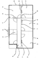
- FIG. 1 is a schematic plan view of a housing equipped with a device according to the invention.
- the subject of the present invention is a reversible heating device that makes it possible to provide heating / air conditioning requirements as well as filtration and dehumidification of residential or tertiary premises, in which at least one service area, such as a corridor, and an area to be treated, such as a living room.
- the single figure schematically shows an apartment in which such a device is installed.
- This generator consists of at least one outdoor unit 1, and at least one indoor unit 2 interconnected by appropriate links.
- the indoor unit (s) 2 ensure the distribution and diffusion of recirculated air with a mixing rate of at least five to six volumes of air, and are equipped with constant or variable flow fans, depending on the choice of users.
- the device In order to transfer the heat energy to rooms 3, the device also comprises a distribution network placed in the sub-ceiling in a common area 4, such as, for example, a corridor, in the example shown.
- a distribution network placed in the sub-ceiling in a common area 4, such as, for example, a corridor, in the example shown.
- This distribution network may be in the form of sheaths arranged between a false ceiling and the upper slab or the roof of the building or, preferably, a plenum at low air velocity, that is to say between 0.8 and 1m / s.
- the flow of hot or cold air flowing in the plenum is blown into the rooms 3 through blowers 5 equipped with low voltage motorized shutters opening and closing in a controlled manner according to the specific needs of each room 3, in order to maintain an individual and independent setpoint temperature.
- the heating and / or air conditioning device according to the invention has electronic regulation means of the flow rate of the air flow flowing through the plenum, allowing a controlled and comfortable distribution of the latter in the parts 3, while preserving the stability of the temperatures of the velocities and the diffusion ranges of air.
- the device according to the invention is also equipped with a discharge port 6 placed under the control of the electronic control means, and for proportionally unloading any excess air flow.
- the device according to the invention may comprise more than one discharge mouth 6.
- the discharge mouth 6 is preferably positioned in an area where constant temperatures are not necessarily required, in a circulation zone, a corridor for example, or in a place favoring easy air intake for the unit. interior.
- the corridor 4 is, therefore, located in the corridor 4, and is preferably equipped with a motorized shutter whose control, controlled by the flow control means of the air flow, s' performs by a signal of the type 0-10V.
- a law of proportionality is established between the air flow resulting from the closures of the blower grids 5 and a voltage emission of 0 to 10V, to discharge the surplus in the zone. selected for this purpose.
- variable-rate indoor units 2 the 0-10V proportionality law is established taking into account the maximum rates of the indoor units 2, and the electronic control means have the function, from the signal of variation of the fan speed of the indoor unit 2, constantly changing the law, so that the 0-10V adapts to the value of the flow rate regulated at the blowing of the indoor unit 2.
- the opening of the motorized shutter of the diffusion mouth 6 is advantageously accompanied by a "ceiling effect", in which the pulsed air sticks the ceiling to the end of its range, avoiding air movements. sensitive in so-called occupancy areas.
- the electronic control means are furthermore provided capable of being informed of the state of opening or closing of the blast grids 5.
- the installation is advantageously completed by room sensors 7 placed in the rooms 3, and can transmit to the electronic control means the values of the temperatures found in each of them.
- the ambient probes 7 are, on the other hand, able to allow the user to select the desired temperature thresholds by simply displaying a setpoint in each equipped room.
- the electronic intercommunication of all the electronic measuring and regulating components is effected by "bus" also allowing the detection of the opening or closing states of the blow-out grids 5, as well as all the data useful for the regulation. electronic.
- the electronic control means are capable of calculating the blowing value of the blast grids 5, in order to control the possible opening of the discharge opening 6 and allow the release of excess air flow to ensure a perfect airflow stability.
- the plenum is then able to convey the right flow of hot or cold air into each room 3 in order to maintain the desired target temperature with a control of the flow rate of the blowing speed, the sound level and the range of diffusion.
- the electronic control means of the device according to the invention are also provided capable of containing all the parameters necessary for its operation and for a personalized programming.
- buttons on the front and display with drop-down menu allowing both a setting of the system by the installation team and a custom programming by the user.
- this module can also be provided with a telecommunication network connection enabling its remote control, by telephone, for troubleshooting in particular, or to check the proper operation of the installation during a routine check, or to start its commissioning or shutdown.
- the device according to the invention also allows considerable energy savings, thanks to a detector opening or closing the doors and windows of the room, combined with electronic temperature control means and the use of a thermodynamic technology whose compressor uses the principle of variable or fixed speed.
- the electronic control means can automatically control the cessation of the production of heat energy or refrigeration in the rooms 3 concerned.
- the electronic device will inhibit the temperature measurements in the room 3 concerned for a period of time so that the cooling in winter or summer warming do not serve as a basis for controlling the operation of the heat production.
- the climatic management is ensured by an electronic equipment which allows taking into account that of the temperatures of the most disadvantaged room 3 to organize the control of the production control of the generator.
- the device has a sprayer equipment, not shown, able to diffuse a product through the installation, for purposes including disinfection or to enhance the atmosphere with a perfume or a deodorant.
- the present invention makes it possible to remedy very simply the problem of regulating the air flow inherent in the devices of the prior art.
- the device according to the present invention is, moreover, particularly remarkable and innovative insofar as it allows both an actual regulation of the room-by-room temperature, a permanent maintenance of the blowing speeds in the plenum and a permanent maintenance of the speeds to the air gratings 5.
Abstract
Description
La présente invention a pour objet un dispositif de chauffage et/ou de climatisation, du type comportant un générateur thermodynamique pour la production d'air chaud et/ou froid, un réseau de distribution de l'air traité, intégré préférentiellement en faux-plafond, et des grilles de soufflage pour diffuser l'air dans les différents locaux à chauffer et/ou à climatiser.The present invention relates to a heating and / or air conditioning device, of the type comprising a thermodynamic generator for the production of hot and / or cold air, a treated air distribution network, preferably integrated in a false ceiling , and blowing grids to diffuse the air in the various premises to be heated and / or to air-condition.
Des dispositifs recherchant des finalités semblables sont couramment utilisés à l'heure actuelle, et sont adaptés aussi bien pour équiper des locaux à usage domestique que pour des installations tertiaires.Devices seeking similar purposes are commonly used at present, and are suitable for both domestic premises and tertiary facilities.
Ils sont, en particulier, fréquemment installés dans des bâtiments résidentiels, collectifs ou individuels.
Plusieurs documents de l'art antérieur décrivent des dispositifs de chauffage du type précité, ainsi que leurs procédés de mise en oeuvre.They are, in particular, frequently installed in residential, collective or individual buildings.
Several documents of the prior art describe heating devices of the aforementioned type, as well as their methods of implementation.
Par exemple, le document WO 94/23249 concerne un système central de chauffage ou de climatisation d'immeubles collectifs basé sur l'utilisation d'unités extérieures et intérieures reliées par des liaisons fluidiques et électriques. Ces unités comprennent de manière classique un compresseur, un ventilateur et un échangeur permettant d'envoyer de l'air sous pression dans un faux plafond étanche, lequel comporte des grilles de soufflage qui débouchent dans chacune des pièces concernées. Dans ce document il est proposé d'utiliser une unité intérieure délivrant, dans un faux plafond formant plénum étanche, de l'air sous une pression ne dépassant pas 8 mm de colonne d'eau.For example, WO 94/23249 relates to a central heating or cooling system of collective buildings based on the use of outdoor and indoor units connected by fluidic and electrical connections. These units typically include a compressor, a fan and a heat exchanger for sending air under pressure in a false ceiling tight, which comprises blowing grids that open into each of the parts concerned. In this document it is proposed to use an indoor unit delivering, in a false ceiling forming a sealed plenum, air under a pressure not exceeding 8 mm of water column.
De manière analogue, les documents WO 97/34112 et WO 99/57491 décrivent des procédés et des dispositifs de climatisation, utilisant également un faux plafond formant plénum étanche, et qui permettent de contrôler le volume d'air soufflé dans les pièces concernées par le biais d'un système permettant de faire varier le degré d'ouverture des grilles de soufflage.Similarly, the documents WO 97/34112 and WO 99/57491 describe methods and devices for air-conditioning, also using a false ceiling forming a sealed plenum, and which make it possible to control the volume of air blown into the parts concerned by means of a system making it possible to vary the degree of opening of the blast grilles.
Le dispositif de climatisation du document WO 97/34112 comprend de plus une unité externe pour générer, selon le cas, de l'énergie chaude ou froide, un réseau de distribution d'un fluide de transport d'énergie chauffante ou rafraîchissante, des unités internes comprenant des moyens pour échanger ladite énergie avec l'air ambiant, un ventilateur et un système de répartition de l'air chauffé ou refroidi équipé de grilles à volets ajustables débouchant dans les pièces intéressées.The air-conditioning device of document WO 97/34112 furthermore comprises an external unit for generating, as the case may be, hot or cold energy, a distribution network for a heating or cooling energy transport fluid, units internal devices comprising means for exchanging said energy with the ambient air, a fan and a heated or cooled air distribution system equipped with adjustable shutter grates opening into the rooms concerned.
Tel qu'il ressort des documents de l'art antérieur précités, les dispositifs disponibles actuellement reposent tous sur la solution classique d'insuffler de l'air chaud ou froid au travers de bouches d'entrée d'air donnant dans les pièces à traiter.As is apparent from the above-mentioned prior art documents, the devices currently available all rely on the conventional solution of blowing hot or cold air through air inlet mouths into the rooms to be treated. .
Cette solution, bien que présentant des avantages quant à la simplicité de mise en oeuvre, présente néanmoins des inconvénients majeurs, relatifs à la fois à la gestion du débit d'air véhiculé, et à la régulation des températures pièce par pièce.This solution, although having advantages as to the simplicity of implementation, nevertheless has major drawbacks, relating both to the management of the air flow conveyed, and to the regulation of room-by-room temperatures.
En effet, l'air arrive avec un débit constant, en permanence dans le réseau de distribution, quel que soit le besoin de chauffage ou de climatisation dans chacune des pièces, et quel que soit l'état d'ouverture ou de fermeture des différentes grilles de soufflage.Indeed, the air arrives with a constant flow, permanently in the distribution network, whatever the need for heating or air conditioning in each of the rooms, and regardless of the state of opening or closing of the different blowing grilles.
Ainsi, lorsque l'une desdites grilles est fermée, le système doit supporter un surplus d'air provoquant un déséquilibre aéraulique qui ne peut être évacué que vers l'intérieur du local, une évacuation vers l'extérieur n'étant pas envisageable en raison du gaspillage important d'énergie que cela entraînerait.Thus, when one of said grids is closed, the system must withstand a surplus of air causing an air imbalance that can only be evacuated towards the interior of the room, an evacuation to the outside not being possible. because of the significant waste of energy that would entail.
Le dispositif du document WO 94/23249 précité prévoit ainsi de libérer cet excédent d'air directement dans une ou plusieurs des pièces de vie du local, provoquant ainsi, régulièrement, des écarts de températures importants lesquels sont à la fois peu confortables et consommateurs d'énergie.The device of the aforementioned document WO 94/23249 thus provides for the release of this excess air directly into one or more of the living rooms of the premises, thus regularly causing significant temperature differences which are both uncomfortable and consumptive to the environment. 'energy.
D'autre part, la solution proposée dans le document WO 99/57491, plus particulièrement destinée à assurer le renouvellement de l'air dans les différentes pièces à vivre, consiste à utiliser des moyens aptes à réguler l'entrée de l'air au niveau des bouches de soufflage donnant dans les différentes pièces.On the other hand, the solution proposed in the document WO 99/57491, more particularly intended to ensure the renewal of the air in the various living rooms, consists in using means able to regulate the entry of air into the room. level of the mouths of blowing giving in the different rooms.
Dans un certain mode de fonctionnement, ces moyens sont informés de l'état d'ouverture ou de fermeture de chacune des bouches de soufflage de l'installation ainsi que de la durée de cet état, et sont aptes à provoquer l'ouverture des éventuelles bouches de soufflage demeurées fermées depuis un laps de temps prédéfini, pour permettre l'introduction d'un certain volume d'air frais dans les pièces concernées, et conjointement, selon le débit d'air disponible, la fermeture des éventuelles bouches de soufflage restées ouvertes dans les pièces dans lesquelles la température de consigne n'était pas atteinte.In a certain mode of operation, these means are informed of the open or closed state of each of the blow-out mouths of the installation and the duration of this state, and are able to cause the opening of any blow-out mouths which have remained closed for a predetermined period of time, to allow the introduction of a certain volume of fresh air into the parts concerned, and jointly, according to the available air flow, the closure of any remaining blast mouths open in rooms where the set temperature was not reached.
La solution que propose ce document, qui revient à insuffler périodiquement un nouveau volume d'air dans certaines pièces à vivre, tout en stoppant l'apport d'air dans d'autres pièces, indépendamment des éventuelles exigences relatives au maintien de leur température, provoque inévitablement des variations brutales de cette dernière tout à fait préjudiciables au confort du logement concerné.The solution proposed by this document, which amounts to periodically inject a new volume of air into some living rooms, while stopping the air supply in other rooms, regardless of any requirements for maintaining their temperature, inevitably provokes brutal variations of the latter which are very detrimental to the comfort of the dwelling concerned.
En outre, un tel dispositif, dans lequel les écarts de températures créés par l'apport, ou l'arrêt de l'apport d'air neuf, doivent sans cesse être compensés, implique une consommation d'énergie particulièrement importante.In addition, such a device, in which temperature deviations created by the intake, or stopping the air supply nine, must constantly be compensated, implies a particularly important energy consumption.
De plus, ce document n'indique pas de manière précise comment sont canalisés les débits qui correspondent aux bouches de soufflage qui se ferment en cas de température de consigne atteinte.In addition, this document does not indicate precisely how are channelized flow rates that correspond to the blowing mouths that close in case of target temperature reached.
De plus encore, le procédé et le dispositif objet de ce document sont d'une utilisation limitée, puisque réservés à l'équipement d'un local comprenant au moins une pièce de service et au moins deux pièces principales.In addition, the method and the device that is the subject of this document are of limited use, since they are reserved for the equipment of a room comprising at least one service room and at least two main rooms.
La présente invention propose par conséquent de pallier ces divers inconvénients grâce à un dispositif destiné à permettre une parfaite maîtrise des températures en toute indépendance dans les pièces desservies, un équilibre aéraulique du réseau de distribution ainsi qu'une régularité des débits, des portées de diffusion d'air et des niveaux sonores aux bouches, quels que soient les états d'ouverture ou de fermeture de diffusion dans les pièces, grâce à une maîtrise efficace de l'excédent d'air, selon une loi de proportionnalité.The present invention therefore proposes to overcome these various drawbacks by means of a device intended to allow a perfect control of the temperatures independently in the rooms served, an aeraulic balance of the distribution network as well as a regularity of the flows, the diffusion ranges of air and sound levels at the mouth, regardless of the opening or closing conditions of diffusion in the rooms, through effective control of the excess air, according to a law of proportionality.
Ainsi, le dispositif selon la présente invention se propose d'améliorer notablement le confort du chauffage et/ou de la climatisation et/ou de déshumidification pièce par pièce en réduisant considérablement les dépenses d'énergie ainsi que les émissions de gaz à effet de serre corollaire.Thus, the device according to the present invention proposes to significantly improve the comfort of heating and / or air conditioning and / or dehumidification piece by room by significantly reducing energy expenditure and greenhouse gas emissions. corollary.
Par ailleurs, la présente invention vise également un dispositif de chauffage à basse température, permettant d'éviter les désagréments liés aux poussières calcinées ainsi qu'aux assèchements d'air l'hiver.Furthermore, the present invention also relates to a low temperature heating device, to avoid the inconvenience associated with calcined dust and air drying in winter.
Enfin, la présente invention a pour objet un dispositif dont la maintenance est facilitée.Finally, the present invention relates to a device whose maintenance is facilitated.
A cet effet, la présente invention concerne un dispositif de chauffage et/ou de climatisation d'un local à usage résidentiel ou tertiaire, dans lequel se situent au moins une zone de service et au moins une pièce à chauffer et/ou climatiser, du type comportant un générateur thermodynamique comprenant au moins une unité intérieure et au moins une unité extérieure communicant entre elles pour produire un flux d'air chauffant et/ou rafraîchissant ; un réseau de distribution intégré en faux-plafond dans ledit local pour distribuer le flux d'air chauffant et/ou rafraîchissant, des grilles de soufflage motorisées pour envoyer, selon les besoins, le flux d'air chauffant et/ou rafraîchissant dans les pièces à chauffer et/ou climatiser, et qui est équipé de moyens de régulation électroniques du débit dudit flux d'air chauffant et/ou rafraîchissant circulant dans ledit réseau de distribution, lesdits moyens de régulation électroniques agissant au niveau dudit réseau de distribution en fonction de l'état d'ouverture ou de fermeture des grilles de soufflage, et qui se caractérise en ce qu'il comprend au moins une bouche de décharge permettant de libérer, le cas échéant, le surplus d'air chauffant et/ou rafraîchissant circulant dans le réseau de distribution et résultant des variations de débit provoquées par les changements d'état des bouches de soufflage motorisées.For this purpose, the present invention relates to a device for heating and / or air conditioning of a room for residential or tertiary use, in which are located at least one service area and at least one room to be heated and / or conditioned, from type comprising a thermodynamic generator comprising at least one indoor unit and at least one outdoor unit communicating with each other to produce a heating and / or cooling air flow; an integrated distribution network in false ceiling in said room to distribute the flow of heating and / or cooling air, motorized blower grids to send, as needed, the flow of heated air and / or cooling in the rooms to be heated and / or conditioned, and which is equipped with electronic means for regulating the flow rate of said heating and / or cooling air flow circulating in said distribution network, said electronic control means acting at said distribution network as a function of the open or closed state of the blow-out grids, and which is characterized in that it comprises at least one discharge opening making it possible, if necessary, to release the surplus of heating and / or cooling air flowing in the distribution network and resulting from flow variations caused by the changes of state of the motorized air outlets.
Selon une caractéristique additionnelle, la ou les bouches de décharge sont situées dans l'une des zones de service.According to an additional feature, the discharge outlet (s) are located in one of the service areas.
Ces particularités permettent de libérer très simplement l'éventuel air en excédent du circuit dans une zone ou un lieu réservés à cet effet, et dans lesquels le confort lié aux températures n'est pas primordial.These features make it possible to very simply release any air in excess of the circuit in a zone or a place reserved for this purpose, and in which the comfort related to the temperatures is not essential.
Selon un mode de réalisation préférentiel, la bouche de décharge est équipée d'un volet motorisé proportionnel.According to a preferred embodiment, the discharge mouth is equipped with a proportional motorized shutter.
Selon une caractéristique additionnelle, les moyens de régulation électroniques du débit du flux d'air chauffant et/ou rafraîchissant comprennent un dispositif de communication avec les grilles de soufflage.According to an additional characteristic, the electronic control means of the flow rate of the heating and / or cooling air flow comprise a device for communication with the blower grids.
Ainsi, le dispositif selon l'invention permet très avantageusement une maîtrise constante de la régularité du débit de l'air dans le gainage de distribution aéraulique en fonction des besoins inhérents à chacune des pièces.Thus, the device according to the invention very advantageously allows a constant control of the regularity of the flow of air in the air distribution cladding according to the needs inherent to each of the parts.
Selon une autre caractéristique, les moyens de régulation électroniques du débit du flux d'air chauffant et/ou rafraîchissant sont équipés d'éléments aptes à commander, selon le cas, l'ouverture ou la fermeture du volet motorisé de la ou les bouches de décharge selon la loi de proportionnalité Qm3/s = S2m2 x Vm/s, où V est la vitesse, Q le débit et S la section.According to another characteristic, the electronic means for regulating the flow rate of the heating and / or cooling air flow are equipped with elements able to control, as the case may be, the opening or closing of the motorized shutter of the or discharge according to the law of proportionality Qm 3 / s = S 2 m 2 x Vm / s, where V is the speed, Q the flow rate and S the section.
Par ailleurs, selon une forme de réalisation préférentielle, du dispositif selon l'invention, les moyens de régulation électroniques du débit du flux d'air chauffant et/ou rafraîchissant comprennent un dispositif de raccordement d'un détecteur de l'état d'ouverture ou de fermeture des portes et fenêtres du local, apte à commander, le cas échéant, l'interruption du chauffage et/ou de la climatisation.Furthermore, according to a preferred embodiment, the device according to the invention, the electronic control means of the flow rate of the heating and / or cooling air flow comprise a connection device of a detector of the open state or closing the doors and windows of the room, able to control, if necessary, the interruption of heating and / or air conditioning.
Cette spécificité permet très avantageusement de réaliser des économies d'énergie supplémentaires non négligeables, de manière automatisée.This specificity makes it very advantageous to achieve significant additional energy savings in an automated manner.
Selon une autre forme de mise en oeuvre envisageable, les moyens de régulation du débit du flux d'air chauffant et/ou rafraîchissant sont, en outre, équipés d'un dispositif permettant le pilotage de la commande domotique de l'installation à distance par liaisons téléphoniques.According to another possible embodiment, the means for regulating the flow rate of the heating and / or cooling air flow are furthermore equipped with a device making it possible to control the home automation control of the remote installation by telephone links.
Ceci autorise également la maintenance et le suivi de l'installation à distance, pour des contrôles de routine, d'assistance de la clientèle ou lorsqu'un éventuel problème surgit.This also allows maintenance and remote monitoring of the installation, for routine checks, customer support or whenever a problem arises.
Selon une autre caractéristique, les moyens de régulation du débit du flux d'air chauffant et/ou rafraîchissant comprennent des moyens de saisie ou de modification des paramètres spécifiques à l'installation.According to another characteristic, the means for regulating the flow rate of the heating and / or cooling air flow comprise means for entering or modifying the parameters specific to the installation.
Grâce à cette caractéristique, le dispositif selon l'invention présente à la fois une centralisation des commandes et de la programmation sur le lieu de l'installation, mais également une possibilité d'intervention à distance.With this feature, the device according to the invention has both a centralization of commands and programming at the place of installation, but also a possibility of remote intervention.
Enfin, selon une autre caractéristique, le dispositif selon l'invention est équipé d'un pulvérisateur apte à diffuser un produit, du type notamment parfum ou désinfectant.Finally, according to another characteristic, the device according to the invention is equipped with a sprayer capable of diffusing a product, of the particular type perfume or disinfectant.
L'invention sera à présent mieux comprise à la lecture de la description qui va suivre, se rapportant à un exemple de réalisation, donné à titre indicatif et non limitatif.The invention will now be better understood on reading the description which follows, referring to an exemplary embodiment, given for information and not limitation.
La compréhension de cette description sera facilitée au vu de la figure jointe en annexe, qui est une vue schématique en plan d'un logement équipé d'un dispositif selon l'invention.The understanding of this description will be facilitated in view of the appended figure, which is a schematic plan view of a housing equipped with a device according to the invention.
La présente invention a pour objet un dispositif de chauffage réversible permettant d'assurer aussi bien les besoins en chauffage/climatisation que la filtration et la déshumidification de locaux résidentiels ou tertiaires, dans lesquels se situent au moins une zone de service, tel qu'un couloir, et une zone à traiter, telle qu'une pièce à vivre.The subject of the present invention is a reversible heating device that makes it possible to provide heating / air conditioning requirements as well as filtration and dehumidification of residential or tertiary premises, in which at least one service area, such as a corridor, and an area to be treated, such as a living room.
La figure unique représente schématiquement un appartement dans lequel est installé un tel dispositif.The single figure schematically shows an apartment in which such a device is installed.
De manière classique ce dernier est du type comportant un générateur thermodynamique, de préférence de type "split" air/air ou air/eau pouvant fonctionner selon le cas :
- en mode hiver, dans lequel il est apte à capter les calories de l'air ou de l'eau, pour les transférer et les diffuser confortablement à l'aide de l'énergie électrique,
- en mode été, dans lequel il capte les calories de l'air dans l'ambiance, pour les transférer et les rejeter vers l'extérieur, tout en déshumidifiant et en abaissant la température ambiante.
- in winter mode, in which it is able to capture calories from air or water, to transfer them and distribute them comfortably with the help of electrical energy,
- in summer mode, in which it captures the calories of the air in the atmosphere, to transfer them and reject them to the outside, while dehumidifying and lowering the ambient temperature.
Ce générateur se compose d'au moins une unité extérieure 1, et d'au moins une unité intérieure 2 reliées entre elles par des liaisons appropriées.This generator consists of at least one outdoor unit 1, and at least one
La ou les unités intérieures 2 assurent la distribution et la diffusion d'air en recyclage avec un taux de brassage de cinq à six volumes d'air au minimum, et sont équipées de ventilateurs à débit constant ou variable, selon le choix des utilisateurs.The indoor unit (s) 2 ensure the distribution and diffusion of recirculated air with a mixing rate of at least five to six volumes of air, and are equipped with constant or variable flow fans, depending on the choice of users.
Afin de transférer l'énergie calorifique vers des pièces 3, le dispositif comprend par ailleurs un réseau de distribution placé en sous-plafond dans une zone 4 commune, tel que par exemple, un couloir, dans l'exemple représenté.In order to transfer the heat energy to
Ce réseau de distribution peut se présenter sous la forme de gaines disposées entre un faux plafond et la dalle supérieure ou le toit de l'immeuble ou, préférentiellement, d'un plénum à basse vitesse de circulation d'air, c'est à dire entre 0,8 et 1m/s.This distribution network may be in the form of sheaths arranged between a false ceiling and the upper slab or the roof of the building or, preferably, a plenum at low air velocity, that is to say between 0.8 and 1m / s.
Le flux d'air chaud ou froid circulant dans le plénum est insufflé dans les pièces 3 au travers de grilles de soufflage 5 équipées de volets motorisés basse tension s'ouvrant et se fermant de manière contrôlée en fonction des besoins propres à chacune des pièces 3, afin d'y maintenir une température de consigne individuelle et indépendante.
Par ailleurs, de manière particulièrement avantageuse, le dispositif de chauffage et/ou de climatisation présente selon l'invention des moyens de régulation électroniques du débit du flux d'air circulant à travers le plénum, permettant une distribution contrôlée et confortable de ce dernier dans les pièces 3, en y préservant la stabilité des températures des vitesses et des portées de diffusion d'air.The flow of hot or cold air flowing in the plenum is blown into the
Moreover, in a particularly advantageous manner, the heating and / or air conditioning device according to the invention has electronic regulation means of the flow rate of the air flow flowing through the plenum, allowing a controlled and comfortable distribution of the latter in the
A cet effet, le dispositif selon l'invention est également équipé d'une bouche de décharge 6 placée sous la commande des moyens de régulation électroniques, et permettant de délester proportionnellement l'éventuel débit d'air excédentaire.For this purpose, the device according to the invention is also equipped with a discharge port 6 placed under the control of the electronic control means, and for proportionally unloading any excess air flow.
On notera que le dispositif selon l'invention peut comporter plus d'une bouche de décharge 6.It will be noted that the device according to the invention may comprise more than one discharge mouth 6.
La bouche de décharge 6 est, de préférence, positionnée dans une zone où des températures constantes ne sont pas nécessairement requises, dans une zone de circulation, un couloir par exemple, ou dans un lieu favorisant une reprise d'air aisée pour l'unité intérieure.The discharge mouth 6 is preferably positioned in an area where constant temperatures are not necessarily required, in a circulation zone, a corridor for example, or in a place favoring easy air intake for the unit. interior.
Dans l'exemple représenté, elle est, par conséquent, située dans le couloir 4, et est, de préférence, équipée d'un volet motorisé dont la commande, pilotée par les moyens de régulation du débit du flux d'air, s'effectue par un signal du type 0-10V.In the example shown, it is, therefore, located in the corridor 4, and is preferably equipped with a motorized shutter whose control, controlled by the flow control means of the air flow, s' performs by a signal of the type 0-10V.
Lorsque le dispositif comprend une ou plusieurs unités intérieures à débit constant, une loi de proportionnalité est établie entre le débit d'air résultant des fermetures des grilles de soufflage 5 et une émission de tension de 0 à 10V, pour décharger le surplus dans la zone sélectionnée à cet effet.When the device comprises one or more constant rate indoor units, a law of proportionality is established between the air flow resulting from the closures of the
Dans le cas d'unités intérieures 2 à débit variable, la loi de proportionnalité 0-10V est établie en tenant compte des débits maximums des unités intérieures 2, et les moyens de régulation électroniques ont pour fonction, à partir du signal de variation de la vitesse du ventilateur de l'unité intérieure 2, de modifier en permanence la loi, afin que le 0-10V s'adapte à la valeur du débit régulé au soufflage de l'unité intérieure 2.In the case of variable-rate
L'ouverture du volet motorisé de la bouche de diffusion 6 s'accompagne avantageusement d'un "effet de plafond", dans lequel l'air pulsé vient coller le plafond jusqu'au terme de sa portée, en évitant les déplacements d'air sensibles dans les zones dites d'occupations.The opening of the motorized shutter of the diffusion mouth 6 is advantageously accompanied by a "ceiling effect", in which the pulsed air sticks the ceiling to the end of its range, avoiding air movements. sensitive in so-called occupancy areas.
De préférence, les moyens de régulation électroniques sont en outre prévus aptes à être informés de l'état d'ouverture ou de fermetures des grilles de soufflage 5.Preferably, the electronic control means are furthermore provided capable of being informed of the state of opening or closing of the
A cet effet, l'installation est avantageusement complétée par des sondes d'ambiance 7 placées dans les pièces 3, et pouvant transmettre aux moyens de régulation électroniques les valeurs des températures relevées dans chacune d'entre elles.For this purpose, the installation is advantageously completed by
Les sondes d'ambiance 7 sont d'autre part, aptes à permettre à l'utilisateur la sélection des seuils de températures qu'il désire par simple affichage de consigne dans chaque pièce équipée. L'intercommunication électronique de l'ensemble des composants électroniques de mesure et de régulation s'effectue par "bus" permettant également la détection des états d'ouverture ou de fermeture des grilles de soufflage 5, ainsi que toutes les données utiles à la régulation électronique.The
Ainsi, les moyens de régulation électroniques sont capables de calculer la valeur de soufflage des grilles de soufflage 5, afin de commander l'ouverture éventuelle de la bouche de décharge 6 et permettre la libération du débit d'air excédentaire afin d'assurer une parfaite stabilité aéraulique.Thus, the electronic control means are capable of calculating the blowing value of the
Le plénum est alors en mesure de véhiculer le juste débit d'air chaud ou froid dans chaque pièce 3 afin d'y maintenir la température de consigne souhaitée avec une maîtrise du débit de la vitesse de soufflage, du niveau sonore et de la portée de diffusion.The plenum is then able to convey the right flow of hot or cold air into each
Par ailleurs, afin d'optimiser l'installation, les moyens de régulation électroniques du dispositif selon l'invention sont également prévus aptes à contenir tous les paramètres nécessaires à son fonctionnement et à une programmation personnalisée.Moreover, in order to optimize the installation, the electronic control means of the device according to the invention are also provided capable of containing all the parameters necessary for its operation and for a personalized programming.
Ainsi, ils se présenteront sous la forme d'un module avec boutons en façade et afficheur avec menu déroulant, permettant aussi bien un paramétrage du système par l'équipe d'installation qu'une programmation personnalisée par l'utilisateur.Thus, they will be in the form of a module with buttons on the front and display with drop-down menu, allowing both a setting of the system by the installation team and a custom programming by the user.
D'autre part, de manière particulièrement avantageuse, ce module peut également être pourvu d'une liaison par réseau de télécommunication permettant son pilotage à distance, par téléphone, pour un dépannage notamment, ou pour vérifier le bon fonctionnement de l'installation lors d'un contrôle de routine, ou encore pour enclencher sa mise en service ou son arrêt.On the other hand, in a particularly advantageous manner, this module can also be provided with a telecommunication network connection enabling its remote control, by telephone, for troubleshooting in particular, or to check the proper operation of the installation during a routine check, or to start its commissioning or shutdown.
Le dispositif selon l'invention permet également de réaliser des économies d'énergie considérables, grâce à un détecteur d'ouverture ou de fermeture des portes et fenêtres du local, combiné aux moyens de régulation électroniques des températures et à l'utilisation d'une technologie thermodynamique dont le compresseur utilise le principe de la vitesse variable ou fixe.The device according to the invention also allows considerable energy savings, thanks to a detector opening or closing the doors and windows of the room, combined with electronic temperature control means and the use of a thermodynamic technology whose compressor uses the principle of variable or fixed speed.
Ainsi, lorsque le système détecte l'ouverture d'une ou de plusieurs fenêtres 9, les moyens de régulation électroniques peuvent automatiquement commander l'arrêt de la production d'énergie calorifique ou frigorifique dans les pièces 3 concernées. A la fermeture des fenêtres, le dispositif électronique inhibera les mesures de températures dans la pièce 3 concernée durant une période temporisée afin que le refroidissement l'hiver ou le réchauffement l'été ne servent pas de base de commande du fonctionnement de la production calorifique.Thus, when the system detects the opening of one or
Selon une autre caractéristique avantageuse du dispositif selon l'invention, la gestion climatique est assurée par un équipement électronique qui permet la prise en compte de celle des températures de la pièce 3 la plus défavorisée pour organiser le pilotage de la commande de production du générateur.According to another advantageous characteristic of the device according to the invention, the climatic management is ensured by an electronic equipment which allows taking into account that of the temperatures of the most
D'autre part, le dispositif dispose d'un équipement de pulvérisateur, non représenté, apte à diffuser un produit à travers l'installation, à des fins notamment de désinfection ou pour agrémenter l'atmosphère à l'aide d'un parfum ou d'un désodorisant.On the other hand, the device has a sprayer equipment, not shown, able to diffuse a product through the installation, for purposes including disinfection or to enhance the atmosphere with a perfume or a deodorant.
Pour des exigences plus sévères, il est également possible de compléter l'ensemble par un système de traitement d'air anti-germicide et anti-bactérien par ultra-violets.For more severe requirements, it is also possible to complete the set with an anti-germicidal and anti-bacterial ultraviolet air treatment system.
Ainsi qu'il ressort clairement de ce qui précède, la présente invention permet de remédier très simplement au problème de régulation du débit d'air inhérent aux dispositifs de l'art antérieur.As is clear from the foregoing, the present invention makes it possible to remedy very simply the problem of regulating the air flow inherent in the devices of the prior art.
Le dispositif selon la présente invention est, en outre, particulièrement remarquable et innovant dans la mesure où il permet à la fois une régulation réelle de la température pièce par pièce, un maintien permanent des vitesses de soufflage dans le plénum et un maintien permanent des vitesses aux grilles de soufflage 5.The device according to the present invention is, moreover, particularly remarkable and innovative insofar as it allows both an actual regulation of the room-by-room temperature, a permanent maintenance of the blowing speeds in the plenum and a permanent maintenance of the speeds to the
Bien que l'invention ait été décrite à propos de quelques formes de réalisation particulières, il est bien entendu qu'elle n'y est nullement limitée et qu'on peut y apporter diverses modifications de forme, de matériaux et de combinaisons de ces divers éléments, sans pour cela s'éloigner du cadre et de l'esprit de l'invention.Although the invention has been described with respect to some particular embodiments, it is understood that it is in no way limited and that various modifications of shape, materials and combinations thereof can be made. without departing from the framework and spirit of the invention.
Claims (9)
- Heating and/or air-conditioning device for a residential- or service-purpose premise in which are located at least one service area and at least one room to be heated and/or to be air-conditioned, of the type including a thermodynamic generator comprising at least one inner unit (2) and at least one external unit communicating between them to produce a heating and/or cooling air-flow, a distribution network integrated into the false ceiling in said premise for distributing the heating and/or cooling air-flow, motorised blowing grids (5) for sending, according to the needs, the heating and/or cooling air-flow into the rooms (3) to be heated and/or air-conditioned, and which is provided with electronic means for regulating the flow rate of said heating and/or cooling air-flow flowing in said distribution network, said electronic regulating means acting at the level of said distribution network according to the state of opening or closing of the blowing grids, characterised in that it includes at least a discharge opening (6) allowing to release the excess of heating and/or cooling air, if any, flowing in the distribution network and resulting from the flow-rate variations caused by the changes in state of the motorised blowing openings.
- Device according to claim 1, characterised in that the discharge opening (6) is provided with a motorised shutter.
- Device according to claim 1 or claim 2, characterised in that the discharge opening (6) is located in one of the service areas (4).
- Device according to any of the preceding claims, characterised in that the electronic means for regulating the flow rate of the heating and/or cooling air flow comprise a device for communicating with the blowing grids (5).
- Device according to any of the preceding claims, characterised in that the electronic means for regulating the flow rate of the heating and/or cooling air flow are provided with elements capable of controlling, as the case may be, the opening or the closing of the motorised shutter of the discharge opening or openings according to the proportionality law Qm3/s = S2m2 x Vm/s, where V is the speed, Q is the flow rate and S is the cross-section.
- Device according to any of the preceding claims, characterised in that the electronic means for regulating the flow rate of the heating and/or cooling air flow comprise a device for connecting a sensor for detecting the state of opening or closing of the doors (8) and windows (9) of the premise, capable of controlling, should the case arise, the interruption of the heating and/or air-conditioning.
- Device according to any of the preceding claims, characterised in that the means for regulating the flow rate of the heating and/or cooling air flow are provided with a device allowing remote control of the home control of the installation through telephone connections.
- Device according to any of the preceding claims, characterised in that the means for regulating the flow rate of the heating and/or cooling air flow comprise means for detecting or changing the parameters specific to the installation.
- Device according to any of the preceding claims, characterised in that it is provided with a sprayer capable of diffusing a product, namely of the type perfume or disinfectant.
Applications Claiming Priority (3)
| Application Number | Priority Date | Filing Date | Title |
|---|---|---|---|
| FR0203118 | 2002-03-13 | ||
| FR0203118A FR2837267B1 (en) | 2002-03-13 | 2002-03-13 | HEATING AND / OR AIR CONDITIONING DEVICE |
| PCT/FR2003/000813 WO2003076850A1 (en) | 2002-03-13 | 2003-03-13 | Heating and/or air-conditioning device |
Publications (2)
| Publication Number | Publication Date |
|---|---|
| EP1490634A1 EP1490634A1 (en) | 2004-12-29 |
| EP1490634B1 true EP1490634B1 (en) | 2006-01-18 |
Family
ID=27772083
Family Applications (1)
| Application Number | Title | Priority Date | Filing Date |
|---|---|---|---|
| EP03743924A Expired - Lifetime EP1490634B1 (en) | 2002-03-13 | 2003-03-13 | Heating and/or air-conditioning device |
Country Status (7)
| Country | Link |
|---|---|
| EP (1) | EP1490634B1 (en) |
| AT (1) | ATE316228T1 (en) |
| AU (1) | AU2003242816A1 (en) |
| DE (1) | DE60303304D1 (en) |
| ES (1) | ES2257684T3 (en) |
| FR (1) | FR2837267B1 (en) |
| WO (1) | WO2003076850A1 (en) |
Families Citing this family (1)
| Publication number | Priority date | Publication date | Assignee | Title |
|---|---|---|---|---|
| PL399933A1 (en) * | 2012-07-12 | 2014-01-20 | Bogdan Sliwinski | Air treatment unit and air treatment unit system |
Family Cites Families (8)
| Publication number | Priority date | Publication date | Assignee | Title |
|---|---|---|---|---|
| IT1228604B (en) * | 1989-01-10 | 1991-06-24 | Aton S R L | EQUIPMENT FOR REMOTE TELEPHONE ACTIVATION OF HEATING AND / OR ENVIRONMENTAL CONDITIONING IN GENERAL, AND THERMOREGULATOR DEVICE USED IN THIS EQUIPMENT. |
| US5279609A (en) * | 1992-10-30 | 1994-01-18 | Milton Meckler | Air quality-temperature controlled central conditioner and multi-zone conditioning |
| FR2703761B1 (en) | 1993-04-06 | 1995-07-13 | Ribo Robert | METHOD AND DEVICE FOR AIR CONDITIONING AND / OR HEATING HOUSING, IN PARTICULAR COLLECTIVE BUILDINGS. |
| US5545086A (en) * | 1994-08-18 | 1996-08-13 | Phoenix Controls Corporation | Air flow control for pressurized room facility |
| FR2745893B1 (en) | 1996-03-11 | 1998-06-05 | Bouvier Georges | METHOD AND DEVICE FOR AIR CONDITIONING AND / OR HEATING WITH HIGH ENERGY EFFICIENCY OF MULTIPLE PREMISES |
| DE19644849A1 (en) * | 1996-10-29 | 1998-05-07 | Kaelte Bast Gmbh | Device for spraying fragrance and method for aromatizing indoor air |
| JP3777528B2 (en) * | 1998-01-20 | 2006-05-24 | 清水建設株式会社 | Indoor air maintenance device |
| FR2778228B1 (en) | 1998-05-04 | 2000-10-06 | Robert Ribo | METHOD AND DEVICE FOR AIR CONDITIONING AND / OR HEATING A PREMISES INCLUDING AT LEAST ONE SERVICE ROOM AND AT LEAST TWO MAIN ROOMS |
-
2002
- 2002-03-13 FR FR0203118A patent/FR2837267B1/en not_active Expired - Fee Related
-
2003
- 2003-03-13 AT AT03743924T patent/ATE316228T1/en not_active IP Right Cessation
- 2003-03-13 EP EP03743924A patent/EP1490634B1/en not_active Expired - Lifetime
- 2003-03-13 DE DE60303304T patent/DE60303304D1/en not_active Expired - Lifetime
- 2003-03-13 WO PCT/FR2003/000813 patent/WO2003076850A1/en not_active Application Discontinuation
- 2003-03-13 AU AU2003242816A patent/AU2003242816A1/en not_active Abandoned
- 2003-03-13 ES ES03743924T patent/ES2257684T3/en not_active Expired - Lifetime
Also Published As
| Publication number | Publication date |
|---|---|
| ATE316228T1 (en) | 2006-02-15 |
| DE60303304D1 (en) | 2006-04-06 |
| ES2257684T3 (en) | 2006-08-01 |
| WO2003076850A1 (en) | 2003-09-18 |
| AU2003242816A1 (en) | 2003-09-22 |
| FR2837267B1 (en) | 2006-09-22 |
| FR2837267A1 (en) | 2003-09-19 |
| EP1490634A1 (en) | 2004-12-29 |
Similar Documents
| Publication | Publication Date | Title |
|---|---|---|
| US9500383B2 (en) | Method for controlling a ventilation system for the ventilation of an enclosure and a ventilation system | |
| KR101121209B1 (en) | Hybrid circulation system | |
| US20210199316A1 (en) | Environmental Control and Air Distribution System and Method of Using the Same | |
| US20190277522A1 (en) | Smart ventilation system | |
| EP1076796B1 (en) | Air conditioning method and device | |
| US11187429B2 (en) | Integrated heat and energy recovery ventilator system | |
| US7398821B2 (en) | Integrated ventilation cooling system | |
| US20080182506A1 (en) | Method for controlling multiple indoor air quality parameters | |
| US20190101302A1 (en) | Air pressure controller for air ventilation devices | |
| AU2013313030A1 (en) | System for optimising an enclosed space | |
| KR20190106608A (en) | Integrated air conditioning control system | |
| EP2244023A1 (en) | Device for air treatment | |
| CN113811751A (en) | Method and system for monitoring air leakage through building envelope and controlling ventilation system | |
| Georges et al. | Simplified space-heating distribution using radiators in super-insulated apartment buildings | |
| KR100966077B1 (en) | Hybrid ventilation system using mechnical and natural ventilation and method thereof | |
| EP1490634B1 (en) | Heating and/or air-conditioning device | |
| KR101021221B1 (en) | Apparatus and method for controling damper of air handling unit | |
| FR2839143A1 (en) | Building air conditioning or heating system has distribution unit that mixes recycled and fresh air | |
| KR101410440B1 (en) | Natural ventilation and heating system using solar radiation energy for buildings | |
| JP2014228518A (en) | Carbon dioxide concentration measuring system, and calibration method of carbon dioxide sensor | |
| JP2759871B2 (en) | Method and apparatus for dehumidifying greenhouse for greenhouse | |
| JPH11351644A (en) | Air conditioner and ventilation system | |
| WO1999043992A1 (en) | Modular, prefabricated and integrated device for heating and ventilating the premises of a building | |
| Nemethova et al. | Thermal Comfort and HVAC Systems Operation Challenges in a Modern Office Building–Case Study | |
| KR20230097231A (en) | Ventillator and Control method thereof |
Legal Events
| Date | Code | Title | Description |
|---|---|---|---|
| PUAI | Public reference made under article 153(3) epc to a published international application that has entered the european phase |
Free format text: ORIGINAL CODE: 0009012 |
|
| 17P | Request for examination filed |
Effective date: 20041012 |
|
| AK | Designated contracting states |
Kind code of ref document: A1 Designated state(s): AT BE BG CH CY CZ DE DK EE ES FI FR GB GR HU IE IT LI LU MC NL PT RO SE SI SK TR |
|
| AX | Request for extension of the european patent |
Extension state: AL LT LV MK |
|
| GRAP | Despatch of communication of intention to grant a patent |
Free format text: ORIGINAL CODE: EPIDOSNIGR1 |
|
| GRAS | Grant fee paid |
Free format text: ORIGINAL CODE: EPIDOSNIGR3 |
|
| GRAA | (expected) grant |
Free format text: ORIGINAL CODE: 0009210 |
|
| AK | Designated contracting states |
Kind code of ref document: B1 Designated state(s): AT BE BG CH CY CZ DE DK EE ES FI FR GB GR HU IE IT LI LU MC NL PT RO SE SI SK TR |
|
| PG25 | Lapsed in a contracting state [announced via postgrant information from national office to epo] |
Ref country code: IT Free format text: LAPSE BECAUSE OF FAILURE TO SUBMIT A TRANSLATION OF THE DESCRIPTION OR TO PAY THE FEE WITHIN THE PRESCRIBED TIME-LIMIT;WARNING: LAPSES OF ITALIAN PATENTS WITH EFFECTIVE DATE BEFORE 2007 MAY HAVE OCCURRED AT ANY TIME BEFORE 2007. THE CORRECT EFFECTIVE DATE MAY BE DIFFERENT FROM THE ONE RECORDED. Effective date: 20060118 Ref country code: IE Free format text: LAPSE BECAUSE OF FAILURE TO SUBMIT A TRANSLATION OF THE DESCRIPTION OR TO PAY THE FEE WITHIN THE PRESCRIBED TIME-LIMIT Effective date: 20060118 Ref country code: FI Free format text: LAPSE BECAUSE OF FAILURE TO SUBMIT A TRANSLATION OF THE DESCRIPTION OR TO PAY THE FEE WITHIN THE PRESCRIBED TIME-LIMIT Effective date: 20060118 Ref country code: NL Free format text: LAPSE BECAUSE OF FAILURE TO SUBMIT A TRANSLATION OF THE DESCRIPTION OR TO PAY THE FEE WITHIN THE PRESCRIBED TIME-LIMIT Effective date: 20060118 Ref country code: GB Free format text: LAPSE BECAUSE OF FAILURE TO SUBMIT A TRANSLATION OF THE DESCRIPTION OR TO PAY THE FEE WITHIN THE PRESCRIBED TIME-LIMIT Effective date: 20060118 Ref country code: AT Free format text: LAPSE BECAUSE OF FAILURE TO SUBMIT A TRANSLATION OF THE DESCRIPTION OR TO PAY THE FEE WITHIN THE PRESCRIBED TIME-LIMIT Effective date: 20060118 Ref country code: SI Free format text: LAPSE BECAUSE OF FAILURE TO SUBMIT A TRANSLATION OF THE DESCRIPTION OR TO PAY THE FEE WITHIN THE PRESCRIBED TIME-LIMIT Effective date: 20060118 Ref country code: SK Free format text: LAPSE BECAUSE OF FAILURE TO SUBMIT A TRANSLATION OF THE DESCRIPTION OR TO PAY THE FEE WITHIN THE PRESCRIBED TIME-LIMIT Effective date: 20060118 Ref country code: RO Free format text: LAPSE BECAUSE OF FAILURE TO SUBMIT A TRANSLATION OF THE DESCRIPTION OR TO PAY THE FEE WITHIN THE PRESCRIBED TIME-LIMIT Effective date: 20060118 |
|
| REG | Reference to a national code |
Ref country code: GB Ref legal event code: FG4D Free format text: NOT ENGLISH |
|
| REG | Reference to a national code |
Ref country code: CH Ref legal event code: EP |
|
| REG | Reference to a national code |
Ref country code: IE Ref legal event code: FG4D Free format text: LANGUAGE OF EP DOCUMENT: FRENCH |
|
| PG25 | Lapsed in a contracting state [announced via postgrant information from national office to epo] |
Ref country code: LU Free format text: LAPSE BECAUSE OF NON-PAYMENT OF DUE FEES Effective date: 20060331 Ref country code: MC Free format text: LAPSE BECAUSE OF NON-PAYMENT OF DUE FEES Effective date: 20060331 Ref country code: BE Free format text: LAPSE BECAUSE OF NON-PAYMENT OF DUE FEES Effective date: 20060331 |
|
| REF | Corresponds to: |
Ref document number: 60303304 Country of ref document: DE Date of ref document: 20060406 Kind code of ref document: P |
|
| PG25 | Lapsed in a contracting state [announced via postgrant information from national office to epo] |
Ref country code: SE Free format text: LAPSE BECAUSE OF FAILURE TO SUBMIT A TRANSLATION OF THE DESCRIPTION OR TO PAY THE FEE WITHIN THE PRESCRIBED TIME-LIMIT Effective date: 20060418 Ref country code: DK Free format text: LAPSE BECAUSE OF FAILURE TO SUBMIT A TRANSLATION OF THE DESCRIPTION OR TO PAY THE FEE WITHIN THE PRESCRIBED TIME-LIMIT Effective date: 20060418 Ref country code: BG Free format text: LAPSE BECAUSE OF FAILURE TO SUBMIT A TRANSLATION OF THE DESCRIPTION OR TO PAY THE FEE WITHIN THE PRESCRIBED TIME-LIMIT Effective date: 20060418 |
|
| PG25 | Lapsed in a contracting state [announced via postgrant information from national office to epo] |
Ref country code: DE Free format text: LAPSE BECAUSE OF FAILURE TO SUBMIT A TRANSLATION OF THE DESCRIPTION OR TO PAY THE FEE WITHIN THE PRESCRIBED TIME-LIMIT Effective date: 20060419 |
|
| PG25 | Lapsed in a contracting state [announced via postgrant information from national office to epo] |
Ref country code: PT Free format text: LAPSE BECAUSE OF FAILURE TO SUBMIT A TRANSLATION OF THE DESCRIPTION OR TO PAY THE FEE WITHIN THE PRESCRIBED TIME-LIMIT Effective date: 20060619 |
|
| NLV1 | Nl: lapsed or annulled due to failure to fulfill the requirements of art. 29p and 29m of the patents act | ||
| REG | Reference to a national code |
Ref country code: ES Ref legal event code: FG2A Ref document number: 2257684 Country of ref document: ES Kind code of ref document: T3 |
|
| GBV | Gb: ep patent (uk) treated as always having been void in accordance with gb section 77(7)/1977 [no translation filed] |
Effective date: 20060118 |
|
| REG | Reference to a national code |
Ref country code: IE Ref legal event code: FD4D |
|
| PLBE | No opposition filed within time limit |
Free format text: ORIGINAL CODE: 0009261 |
|
| STAA | Information on the status of an ep patent application or granted ep patent |
Free format text: STATUS: NO OPPOSITION FILED WITHIN TIME LIMIT |
|
| 26N | No opposition filed |
Effective date: 20061019 |
|
| REG | Reference to a national code |
Ref country code: CH Ref legal event code: PL |
|
| BERE | Be: lapsed |
Owner name: JUAREZ, YVES Effective date: 20060331 |
|
| PG25 | Lapsed in a contracting state [announced via postgrant information from national office to epo] |
Ref country code: LI Free format text: LAPSE BECAUSE OF NON-PAYMENT OF DUE FEES Effective date: 20070331 Ref country code: CH Free format text: LAPSE BECAUSE OF NON-PAYMENT OF DUE FEES Effective date: 20070331 |
|
| PG25 | Lapsed in a contracting state [announced via postgrant information from national office to epo] |
Ref country code: CZ Free format text: LAPSE BECAUSE OF FAILURE TO SUBMIT A TRANSLATION OF THE DESCRIPTION OR TO PAY THE FEE WITHIN THE PRESCRIBED TIME-LIMIT Effective date: 20060118 Ref country code: GR Free format text: LAPSE BECAUSE OF FAILURE TO SUBMIT A TRANSLATION OF THE DESCRIPTION OR TO PAY THE FEE WITHIN THE PRESCRIBED TIME-LIMIT Effective date: 20060419 |
|
| PG25 | Lapsed in a contracting state [announced via postgrant information from national office to epo] |
Ref country code: EE Free format text: LAPSE BECAUSE OF FAILURE TO SUBMIT A TRANSLATION OF THE DESCRIPTION OR TO PAY THE FEE WITHIN THE PRESCRIBED TIME-LIMIT Effective date: 20060118 |
|
| PG25 | Lapsed in a contracting state [announced via postgrant information from national office to epo] |
Ref country code: HU Free format text: LAPSE BECAUSE OF FAILURE TO SUBMIT A TRANSLATION OF THE DESCRIPTION OR TO PAY THE FEE WITHIN THE PRESCRIBED TIME-LIMIT Effective date: 20060719 Ref country code: TR Free format text: LAPSE BECAUSE OF FAILURE TO SUBMIT A TRANSLATION OF THE DESCRIPTION OR TO PAY THE FEE WITHIN THE PRESCRIBED TIME-LIMIT Effective date: 20060118 |
|
| PG25 | Lapsed in a contracting state [announced via postgrant information from national office to epo] |
Ref country code: CY Free format text: LAPSE BECAUSE OF FAILURE TO SUBMIT A TRANSLATION OF THE DESCRIPTION OR TO PAY THE FEE WITHIN THE PRESCRIBED TIME-LIMIT Effective date: 20060118 |
|
| PGFP | Annual fee paid to national office [announced via postgrant information from national office to epo] |
Ref country code: ES Payment date: 20100408 Year of fee payment: 8 |
|
| REG | Reference to a national code |
Ref country code: ES Ref legal event code: FD2A Effective date: 20120509 |
|
| PG25 | Lapsed in a contracting state [announced via postgrant information from national office to epo] |
Ref country code: ES Free format text: LAPSE BECAUSE OF NON-PAYMENT OF DUE FEES Effective date: 20110314 |
|
| PGFP | Annual fee paid to national office [announced via postgrant information from national office to epo] |
Ref country code: FR Payment date: 20130923 Year of fee payment: 11 |
|
| REG | Reference to a national code |
Ref country code: FR Ref legal event code: ST Effective date: 20141128 |
|
| PG25 | Lapsed in a contracting state [announced via postgrant information from national office to epo] |
Ref country code: FR Free format text: LAPSE BECAUSE OF NON-PAYMENT OF DUE FEES Effective date: 20140331 |