EP1489856A2 - Video recording and reproducing apparatus and method - Google Patents
Video recording and reproducing apparatus and method Download PDFInfo
- Publication number
- EP1489856A2 EP1489856A2 EP04006418A EP04006418A EP1489856A2 EP 1489856 A2 EP1489856 A2 EP 1489856A2 EP 04006418 A EP04006418 A EP 04006418A EP 04006418 A EP04006418 A EP 04006418A EP 1489856 A2 EP1489856 A2 EP 1489856A2
- Authority
- EP
- European Patent Office
- Prior art keywords
- recording
- signal
- video
- control information
- video signal
- Prior art date
- Legal status (The legal status is an assumption and is not a legal conclusion. Google has not performed a legal analysis and makes no representation as to the accuracy of the status listed.)
- Withdrawn
Links
Images


Classifications
-
- H—ELECTRICITY
- H04—ELECTRIC COMMUNICATION TECHNIQUE
- H04N—PICTORIAL COMMUNICATION, e.g. TELEVISION
- H04N5/00—Details of television systems
- H04N5/76—Television signal recording
-
- G—PHYSICS
- G11—INFORMATION STORAGE
- G11B—INFORMATION STORAGE BASED ON RELATIVE MOVEMENT BETWEEN RECORD CARRIER AND TRANSDUCER
- G11B27/00—Editing; Indexing; Addressing; Timing or synchronising; Monitoring; Measuring tape travel
- G11B27/02—Editing, e.g. varying the order of information signals recorded on, or reproduced from, record carriers
- G11B27/031—Electronic editing of digitised analogue information signals, e.g. audio or video signals
- G11B27/034—Electronic editing of digitised analogue information signals, e.g. audio or video signals on discs
-
- G—PHYSICS
- G11—INFORMATION STORAGE
- G11B—INFORMATION STORAGE BASED ON RELATIVE MOVEMENT BETWEEN RECORD CARRIER AND TRANSDUCER
- G11B27/00—Editing; Indexing; Addressing; Timing or synchronising; Monitoring; Measuring tape travel
- G11B27/10—Indexing; Addressing; Timing or synchronising; Measuring tape travel
- G11B27/102—Programmed access in sequence to addressed parts of tracks of operating record carriers
- G11B27/105—Programmed access in sequence to addressed parts of tracks of operating record carriers of operating discs
-
- G—PHYSICS
- G11—INFORMATION STORAGE
- G11B—INFORMATION STORAGE BASED ON RELATIVE MOVEMENT BETWEEN RECORD CARRIER AND TRANSDUCER
- G11B27/00—Editing; Indexing; Addressing; Timing or synchronising; Monitoring; Measuring tape travel
- G11B27/10—Indexing; Addressing; Timing or synchronising; Measuring tape travel
- G11B27/19—Indexing; Addressing; Timing or synchronising; Measuring tape travel by using information detectable on the record carrier
- G11B27/28—Indexing; Addressing; Timing or synchronising; Measuring tape travel by using information detectable on the record carrier by using information signals recorded by the same method as the main recording
- G11B27/30—Indexing; Addressing; Timing or synchronising; Measuring tape travel by using information detectable on the record carrier by using information signals recorded by the same method as the main recording on the same track as the main recording
- G11B27/3027—Indexing; Addressing; Timing or synchronising; Measuring tape travel by using information detectable on the record carrier by using information signals recorded by the same method as the main recording on the same track as the main recording used signal is digitally coded
-
- G—PHYSICS
- G11—INFORMATION STORAGE
- G11B—INFORMATION STORAGE BASED ON RELATIVE MOVEMENT BETWEEN RECORD CARRIER AND TRANSDUCER
- G11B27/00—Editing; Indexing; Addressing; Timing or synchronising; Monitoring; Measuring tape travel
- G11B27/10—Indexing; Addressing; Timing or synchronising; Measuring tape travel
- G11B27/19—Indexing; Addressing; Timing or synchronising; Measuring tape travel by using information detectable on the record carrier
- G11B27/28—Indexing; Addressing; Timing or synchronising; Measuring tape travel by using information detectable on the record carrier by using information signals recorded by the same method as the main recording
- G11B27/32—Indexing; Addressing; Timing or synchronising; Measuring tape travel by using information detectable on the record carrier by using information signals recorded by the same method as the main recording on separate auxiliary tracks of the same or an auxiliary record carrier
- G11B27/327—Table of contents
- G11B27/329—Table of contents on a disc [VTOC]
-
- G—PHYSICS
- G11—INFORMATION STORAGE
- G11B—INFORMATION STORAGE BASED ON RELATIVE MOVEMENT BETWEEN RECORD CARRIER AND TRANSDUCER
- G11B2220/00—Record carriers by type
- G11B2220/20—Disc-shaped record carriers
- G11B2220/21—Disc-shaped record carriers characterised in that the disc is of read-only, rewritable, or recordable type
- G11B2220/215—Recordable discs
- G11B2220/216—Rewritable discs
-
- G—PHYSICS
- G11—INFORMATION STORAGE
- G11B—INFORMATION STORAGE BASED ON RELATIVE MOVEMENT BETWEEN RECORD CARRIER AND TRANSDUCER
- G11B2220/00—Record carriers by type
- G11B2220/20—Disc-shaped record carriers
- G11B2220/25—Disc-shaped record carriers characterised in that the disc is based on a specific recording technology
- G11B2220/2508—Magnetic discs
- G11B2220/2516—Hard disks
-
- G—PHYSICS
- G11—INFORMATION STORAGE
- G11B—INFORMATION STORAGE BASED ON RELATIVE MOVEMENT BETWEEN RECORD CARRIER AND TRANSDUCER
- G11B2220/00—Record carriers by type
- G11B2220/20—Disc-shaped record carriers
- G11B2220/25—Disc-shaped record carriers characterised in that the disc is based on a specific recording technology
- G11B2220/2537—Optical discs
- G11B2220/2562—DVDs [digital versatile discs]; Digital video discs; MMCDs; HDCDs
- G11B2220/2575—DVD-RAMs
-
- G—PHYSICS
- G11—INFORMATION STORAGE
- G11B—INFORMATION STORAGE BASED ON RELATIVE MOVEMENT BETWEEN RECORD CARRIER AND TRANSDUCER
- G11B2220/00—Record carriers by type
- G11B2220/40—Combinations of multiple record carriers
- G11B2220/45—Hierarchical combination of record carriers, e.g. HDD for fast access, optical discs for long term storage or tapes for backup
- G11B2220/455—Hierarchical combination of record carriers, e.g. HDD for fast access, optical discs for long term storage or tapes for backup said record carriers being in one device and being used as primary and secondary/backup media, e.g. HDD-DVD combo device, or as source and target media, e.g. PC and portable player
-
- H—ELECTRICITY
- H04—ELECTRIC COMMUNICATION TECHNIQUE
- H04N—PICTORIAL COMMUNICATION, e.g. TELEVISION
- H04N5/00—Details of television systems
- H04N5/76—Television signal recording
- H04N5/78—Television signal recording using magnetic recording
- H04N5/781—Television signal recording using magnetic recording on disks or drums
-
- H—ELECTRICITY
- H04—ELECTRIC COMMUNICATION TECHNIQUE
- H04N—PICTORIAL COMMUNICATION, e.g. TELEVISION
- H04N5/00—Details of television systems
- H04N5/76—Television signal recording
- H04N5/84—Television signal recording using optical recording
- H04N5/85—Television signal recording using optical recording on discs or drums
-
- H—ELECTRICITY
- H04—ELECTRIC COMMUNICATION TECHNIQUE
- H04N—PICTORIAL COMMUNICATION, e.g. TELEVISION
- H04N9/00—Details of colour television systems
- H04N9/79—Processing of colour television signals in connection with recording
- H04N9/80—Transformation of the television signal for recording, e.g. modulation, frequency changing; Inverse transformation for playback
- H04N9/804—Transformation of the television signal for recording, e.g. modulation, frequency changing; Inverse transformation for playback involving pulse code modulation of the colour picture signal components
- H04N9/8042—Transformation of the television signal for recording, e.g. modulation, frequency changing; Inverse transformation for playback involving pulse code modulation of the colour picture signal components involving data reduction
-
- H—ELECTRICITY
- H04—ELECTRIC COMMUNICATION TECHNIQUE
- H04N—PICTORIAL COMMUNICATION, e.g. TELEVISION
- H04N9/00—Details of colour television systems
- H04N9/79—Processing of colour television signals in connection with recording
- H04N9/80—Transformation of the television signal for recording, e.g. modulation, frequency changing; Inverse transformation for playback
- H04N9/804—Transformation of the television signal for recording, e.g. modulation, frequency changing; Inverse transformation for playback involving pulse code modulation of the colour picture signal components
- H04N9/806—Transformation of the television signal for recording, e.g. modulation, frequency changing; Inverse transformation for playback involving pulse code modulation of the colour picture signal components with processing of the sound signal
- H04N9/8063—Transformation of the television signal for recording, e.g. modulation, frequency changing; Inverse transformation for playback involving pulse code modulation of the colour picture signal components with processing of the sound signal using time division multiplex of the PCM audio and PCM video signals
-
- H—ELECTRICITY
- H04—ELECTRIC COMMUNICATION TECHNIQUE
- H04N—PICTORIAL COMMUNICATION, e.g. TELEVISION
- H04N9/00—Details of colour television systems
- H04N9/79—Processing of colour television signals in connection with recording
- H04N9/80—Transformation of the television signal for recording, e.g. modulation, frequency changing; Inverse transformation for playback
- H04N9/82—Transformation of the television signal for recording, e.g. modulation, frequency changing; Inverse transformation for playback the individual colour picture signal components being recorded simultaneously only
- H04N9/8205—Transformation of the television signal for recording, e.g. modulation, frequency changing; Inverse transformation for playback the individual colour picture signal components being recorded simultaneously only involving the multiplexing of an additional signal and the colour video signal
- H04N9/8227—Transformation of the television signal for recording, e.g. modulation, frequency changing; Inverse transformation for playback the individual colour picture signal components being recorded simultaneously only involving the multiplexing of an additional signal and the colour video signal the additional signal being at least another television signal
Definitions
- the present invention relates to a video recording and reproducing apparatus that can record and reproduce videos broadcast by a broadcasting satellite or a communication satellite or using an electric wave in a VHF band or a UHF band, and in particular, to a video recording and reproducing apparatus in conformity with a DVD-VR standard.
- Television apparatuses are commonly used as display apparatuses that display videos.
- Widely employed television systems include an NTSC system mainly employed in Japan and other Asian areas and using 525 scanning lines and a PAL system that is a 625/50 line system mainly employed in Europe.
- WSS Wide Screen Signaling information
- VBI Very Blanking Interval
- WSS For the WSS, aspect information, subtitles, copy control information, and the like are specified. These pieces of information are set for a line 23 that is an effective video line.
- the following 11 publications propose a technique used if the signal (WSS) superimposed on the VBI is recorded in a digital medium such as an optical disk, to detect the signal superimposed on the VBI and record it in an area in which the aspect information and copy control information are set: Jpn. Pat. Appln. KOKAI Publication No. 2001-86444, Jpn. Pat. Appln. KOKAI Publication No. 2001-86455, Jpn. Pat. Appln. KOKAI Publication No. 2001-86463, Jpn. Pat. Appln. KOKAI Publication No. 2001-86464, Jpn. Pat. Appln. KOKAI Publication No. 2001-86465, Jpn. Pat. Appln. KOKAI Publication No.
- this signal is outputted directly to a television receiver (a monitor apparatus) that is not adapted for the WSS, then disadvantageously a white line (an unwanted image) may be displayed in an effective video line at the top of a display image.
- Another problem is that when a signal recorded as a wide signal (an aspect ratio of 16:9) is reproduced in a letter size, the above white line may occur near the center of the display screen.
- a video recording and reproducing apparatus comprising: a signal receiving section which receives a video signal or an audio signal; an encode section which encodes the video signal or the audio signal received by the signal receiving section into a predetermined form; a recording device which records the video signal and management information for the video signal in a recording medium; a control information signal detecting device which detects that a vertical blanking interval of the video signal received by the signal receiving section contains a control information signal that may be outputted to an effective video area; and a recording control device which operates if the control information signal detecting device detects containment of the control information signal, to set a flag indicative of the containment of the control information signal in a predetermined area of a management information recording area of the recording medium.
- a video recording and reproducing apparatus comprising: a signal receiving section which receives a video signal or an audio signal; an encode section which encodes the video signal or the audio signal received by the signal receiving section into a predetermined form; a recording device which records the video signal and management information for the video signal in a recording medium; a control information signal detecting device which detects that a vertical blanking interval of the video signal received by the signal receiving section contains a control information signal that may be outputted to an effective video area; and a recording reservation information retaining section which retains recording reservation information including a start and end of recording of the video signal in the recording medium as well as recording conditions which recording is executed by the recording device as well as recording conditions; and a recording control device which operates if the control information signal detecting device detects containment of the control information signal when a main power supply is turned on by the recording reservation information retaining device, to set a flag indicative of the containment of the control information signal in a predetermined area of a management information recording area of the
- An aspect of the invention there is provided to a video recording method comprising: detecting a vertical blanking interval of a video signal received by the signal receiving section contains a control information signal that may be outputted to an effective video area; and if it is detected that the vertical blanking interval of the received video signal contains the control information signal, setting a flag indicative of the containment of the control information signal in a predetermined area of a management information recording area of the recording medium.
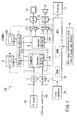
- FIG. 1 is a block diagram illustrating an example of the configuration of a video recording and reproducing apparatus to which an embodiment of the present invention is applied.
- a video recording and reproducing apparatus 100 has a TV tuner 100 that selectively receives space transmission as radio wave, i.e., broadcasting signal wave of a predetermined channel broadcast by a broadcasting satellite or a communication satellite or using an electric wave in a VHF band or a UHF band, and an external input terminal 102 to which video signals and audio signals can be inputted.
- radio wave i.e., broadcasting signal wave of a predetermined channel broadcast by a broadcasting satellite or a communication satellite or using an electric wave in a VHF band or a UHF band
- a video signal and an audio signal inputted through the television tuner (signal receiving section) 101 or the external input terminal (signal receiving section) 102 are received to a video analog-digital (A/D) converting circuit 3 and an audio analog-digital (A/D) converting circuit 4, respectively, via a video input section 1 and an audio input section 2, respectively.
- the converting circuits convert the analog video and audio signals into a video digital signal and an audio digital signal, respectively.
- a video digital signal and an audio digital signal are inputted to a buffer memory 105 of an encoder 5.
- the signals are then subjected to predetermined signal processing in accordance with an instruction (control command) from an MPU 18, described later.
- the video digital signal is encoded into compressed video data in conformity with, for example, an MPEG2 standard.
- the audio digital signal is encoded into compressed audio data in conformity with, for example, AC3 or MPEG2.
- the compressed video data and compressed audio data are converted by an encoder 5 into an MPEG2 system layer.
- the signals from the encoder 5 are converted by a formatter 6 into a format specified in a DVD recording standard (DVD-RAM, DVD-RW, or the like).
- the signals having their format converted by the formatter 6 are converted by a data processing section 7 into recording data containing commands in conformity with a DVD-RAM drive 8 or a hard disk drive (HDD) 8.
- the data is then recorded in a DVD-RAM disk M preset in a DVD-RAM drive 8 or in a hard disk (HD).
- a data processing section 7 is mainly composed of a buffer circuit.
- the data processing section 7 also functions as a disk controller in transferring recording data between the HDD 9 and the DVD-RAM drive 8, recording the recording data in the HDD 9 or the DVD-RAM drive 8, or reading data from the hard disk HD or the DVD-RAM disk M, set in the DVD-RAM drive 8.
- reproduction management information created by the MPU 18 is recorded in the DVD-RAM disk or the hard disk (HD) via the data processing section 7.
- the MPU 18 can edit a plurality of programs recorded in the DVD-RAM disk M or the hard disk (HD).
- already recorded programs can be deleted or reproduced for edition using a method dealing with an already published DVD format (this method is not described in detail).
- the MPU 18 modifies management information corresponding to the recording data.
- the data read from the DVD-RAM disk M or the hard disk (HD) is inputted to the data processing section 7.
- An output (read output) from the data processing section 7 is inputted to a decoder 10.
- the read output inputted to the decoder 10 is decoded from the DVD format.
- the decoder 10 mainly has a separating section that separates the read data of the DVD format into video data and audio data and a section that decodes the compressed video data and compressed audio data separated from each other.
- the vide data is decoded from the MPEG2 format
- the audio data is decoded from the MPEG, AC3, or the like.
- the decoded video and audio data are outputted to selectors 11a and 11b, respectively.
- the video data outputted by the selector 11a is converted by a video D/A converting circuit 23 into a video analog signal.
- the signal is then outputted to a monitor device (a display) 14 or a video input section of the television receiver.
- the audio data outputted by the selector 11b is converted by an audio D/A converting circuit 13 into an audio analog signal.
- the signal is then inputted to a speaker 15 or an audio input section of the television receiver.
- the MPU 18 performs an operation of receiving a user command from a key input section 16 and controlling the operations of individual circuits or units of the video recording and reproducing apparatus 100.
- the MPU 18 includes a RAM that temporarily retains inputted commands, parameters, and the like and a ROM in which control programs and the like are stored, in order to enable inputting of operations of the video recording and reproducing apparatus 100, for example, recording start (REC), image reproduction (PLAY), (recording and reproduction) stop (STOP), and skip (SKIP), inputting of a time setting/reserved time (HOUR, MIN, DAY, MONTH), inputting of reservation conditions (RATE, MODE, HDD, DISK), inputting of a control signal corresponding to reset (COUNTER RESET) or the like, turning on/off of the main power supply, and the like.
- the MPU 18 thus controls operations of the whole system, accepts user commands, displays the present state, or detects the DVD format in accordance with the control programs.
- a timer computer 19 is connected to the MPU 18.
- the timer computer 114 turns on a main power supply at a preset time or a predetermined time before the preset time even if a main power supply circuit (not shown) of the video recording and reproducing apparatus 100 is off.
- the timer computer 114 thus causes each section of the main body of the apparatus 100 to stand by and get ready for recording before reserved recording is started. For example, when the reserved time is reached, the timer computer 19 sets broadcasting (a program) of a reserved channel under preset recording conditions to enable the reserved recording of videos and sounds.
- FIGS. 2 and 3 are schematic diagrams illustrating a DVD-VR (DVD Video Recording) standard required to record recording data utilized in the video recording and reproducing apparatus shown in FIG. 1.
- DVD-VR DVD Video Recording
- VRO VRO
- IFO IFO
- management information such as a recorded position of the data and title information is recorded (there is also a file for still images but its description is omitted in the present proposal).
- Information on motion pictures and sounds is recorded in the VRO file using an MPEG2 program stream system. If a plurality of recording operations (recording of information) are performed, then after the first data has been recorded, the second data is recorded in the same file.
- the IFO (information) file is provided to manage individual recording data.
- M_VOB Motion Picture Data created by a single recording operation
- the IFO file indicates where in the file each M_VOB is recorded. This area of the IFO file is called M_VOBI (Movie Video Object Information).
- VOB video object
- the VOB is stored in the above described video file called the VR_MOVIE. VRO file.
- the video file has a hierarchical structure and is composed of one or more VOBs (Video OBjects).
- VOB is composed of one or more VOBUs (Video OBject Units).
- One VOBU is composed of a plurality of packs.
- the plurality of packs include an RDI pack, a V (Video) pack, and an A (Audio) pack.
- a sub-video pack (SP pack) may be present.
- the RDI pack is called a unit control information pack or a navigation information pack or a real time data information pack (RDI_PACK).
- This pack contains information indicative of a start time when the first field of the VOBU to which the pack belongs is reproduced, information indicative of a time when the VOBU is to be recorded, and manufacturer information (MNFI).
- the pack also contains display control information (DCI) and copy control information (CCI).
- the display control information is indicative of aspect ratio information, subtitle mode information, and film camera mode information.
- the copy control information includes copy enable information (0, 0) or copy disable (prohibition) information (1, 1).
- the V pack is video data compressed using the MPEG2 system.
- the V pack is composed of a pack header, a packet header, and a video data section.
- the A pack is audio data encoded using, for example, a linear PCM system, the MPEG system, or the AC3 system.
- the A pack is composed of a pack header, a packet header, and an audio data section.
- the management information is stored in the above described management information called the VR_MANGR. IFO.
- the management information is called a video manager (VMG) and a program chain (PGC) is defined in the management information to manage the order of data reproduction. Cells are defined in the PGC.
- the PGC describes and specifies the order of a plurality of cells. Each of the cells defines video object information (VOBI) on a video object (VOB) to be reproduced.
- VOBI video object information
- PGCI program chain information
- ORG_PGCI original PGCI
- U-PGCIT user defined PGC table
- the original PGCI is created during recording.
- the user defined PGC table (UD_PGCIT) is created as management information known as a play list when the video object managed by the original PGC is edited (deletion, addition, or decimation).
- the RDI pack shown in FIGS. 2 and 3 has flags for the aspect information (DCI) and copy control information (CCI). If WSS (Wide Screen Signalling information) is detected, it is described in these pieces of information.
- DCI aspect information
- CCI copy control information
- Flags inherent in the WSS includes the MSB of DCI_SS and a Subtitle and Film Camera Code flags in the DCI data as shown in FIG. 3.
- the WSS Wide Screen Signalling information
- VBI Very Blanking Interval
- a television receiver (a monitor apparatus) connected to the video digital-analog converting circuit 12, previously described with reference to FIG. 1, is not adapted for the WSS, then disadvantageously a white line (an unwanted image) may be displayed in an effective video line at the top of a display image on the television receiver (monitor apparatus).
- a WSS component when a video signal containing WSS is reproduced, a WSS component is inhibited from being reproduced in an effective image area of a display device.
- the present invention has characteristics such as those shown in FIG. 4.
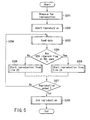
- FIG. 4 is a flow chart illustrating an example of operations performed to record a video using the DVD-VR format.
- the WSS signal is superimposed on the VBI (S103). If the WSS is not detected (S103-No), a setting inherent in the case in which the WSS is superimposed is not added to the RDI pack (S104).
- the DCI_SS in FIG. 3 is set in 01(b). Specifically, the 01(b) flag is set in the DCI_SS to indicate that the WSS is not superimposed.
- the video signal starts to be encoded from a line 23 (S105).
- the encoded data is recorded in a recording medium, for example, the hard disk (HD) or the DVD-RAM disk M (S108).
- the setting inherent in the case in which the WSS is superimposed on the VBI is added to the RDI pack (S106).
- the DCI_SS in FIG. 3 is set in 11(b).
- the 11(b) flag is set in the DCI_SS to indicate that the WSS is superimposed.
- the aspect information of the DCI is indicative of a ratio other than 4:3 and 16:9, then that value is set. If a subtitle mode or a frame camera mode is detected, a predetermined DCI flag is set.
- the video signal starts to be encoded from a line 24 (S107).
- the encoded data is recorded in a recording device (S108).
- the line to which the image is outputted can be easily changed by, for example, switching the output between the data for the line 23 and the data for the line 24 when outputting (transferring) the data from the buffer 105 of the encoder 5 to the data processing section 7 or from the data processing section 7 to the hard disk (HD) or DVD-RAM disk M.
- the above single period corresponds to the one VOBU interval shown in FIG. 2.
- the recording is executed, for example, on the basis of a recording reservation already registered in the timer computer 19.
- the main power supply is turned on, for example, about 15 to 5 seconds before the reserved time to execute reserved recording. Accordingly, the detection of the WSS, described in step S104, can be achieved before the actual time to start recording.
- a recording start line is shifted by one line in accordance with each step shown in FIG. 4 even if the WSS is superimposed on the VBI.
- FIG. 5 is a flow chart illustrating an example of operations performed to reproduce a video using the DVD-VR format.
- the RDI pack contains the flag inherent in the WSS (S204).
- the DSI_SS in FIG. 3 is 11(b), that is, the flag 11(b) is set, then the WSS is on. Otherwise the WSS is off.
- reproduction image output
- line 23 S205
- S204-Yes reproduction (image output) is started with the line 24 (S206).
- the line to which the image is outputted can be easily changed by, for example, switching the output between the data for the line 23 and the data for the line 24 when transferring the reproduced data from the buffer 105 of the encoder 5 or the data processing section 7 to the decoder 10 or from the data processing section 7 to the decoder 10. If the WSS is off or undetectable, it may be outputted as black data when the data for the line 23 is outputted.
- the flag inherent in the WSS is written in the RDI pack, and before reproduction, it is detected whether or not the flag is present to determine whether the WSS is on or off.
- WSS information other than that contained in the RDI pack can be recorded and reproduced by, for example, recording all of WSS detection data in MPEG2 user data and before reproduction, using the user data to make determination.
- the video recording apparatus shifts the effective recording start line by one line to the line 24.
- a reproducing device shifts the reproducing effective video start line by one line to the line 24.
- Any WSS detecting method may be used provided that it can achieve accurate detections.
- the video recording and reproducing apparatus may have any configuration without departing from the spirits of the present invention.
- any procedure other than the one used in the present embodiment may be used without departing from the spirits of the present invention.
- the present invention is not limited to the above described embodiment. Arbitrary variations or changes may be made to the above embodiment without departing the spirits of the present invention.
- videos and sounds are recorded.
- equivalent operations and effects can be achieved even if only sounds are recorded.
- the video recording and reproducing apparatus uses an optical disk (RAM disk) or hard disk as a recording medium.
- equivalent operations and effects can be achieved using, for example, a conventional video tape recorder provided that the video tape recorder has equivalent characteristics.
- the present invention prevents unwanted images from being outputted to the effective video area of the image display section if the VBI information on which the WSS information is superimposed is inputted. This improves image quality obtained when a video program is reproduced.
Abstract
Description
Claims (15)
- A video recording and reproducing apparatus (100) characterized by comprising:a signal receiving section (101, 102) which receives a video signal or an audio signal;an encode section (5) which encodes the video signal or the audio signal received by the signal receiving section into a predetermined form;a recording device (8, 9) which records the video signal and management information for the video signal in a recording medium;a control information signal detecting device (5, 6) which detects that a vertical blanking interval of the video signal received by the signal receiving section contains a control information signal that may be outputted to an effective video area; anda recording control device (7, 18) which operates if the control information signal detecting device detects containment of the control information signal, to set a flag indicative of the containment of the control information signal in a predetermined area of a management information recording area of the recording medium.
- The video recording and reproducing apparatus according to claim 1, characterized in that if the control information signal detecting device (5, 6) detects containment of the control information signal, when the video signal received by the signal receiving section is recorded in the recording medium, the recording control device (7, 18) encodes the video signal starting with a vertical blanking interval following the one containing the control information signal.
- The video recording and reproducing apparatus according to claim 1, characterized by further comprising:wherein if the control information signal recording section detecting device detects the presence of the flag, when the video signal recorded in the recording medium is reproduced, the recording control device (7, 18) decodes the video signal starting with a vertical blanking interval following the one containing the control information signal.a control information signal recording section detecting device (5, 6) which detects whether or not the flag is present; anda video signal decoding device which reproduces and decodes the video signal recorded in the recording medium,
- A video recording and reproducing apparatus (100) according to claim 1, characterized in that
the recording control device (7, 18) operates if the control information signal detecting device (5, 6) detects containment of the control information signal to causes the recording device (8, 9) to record the video signal starting with a vertical blanking interval following the one containing the control information signal when the video signal to be recorded in the recording medium is outputted. - The video recording and reproducing apparatus according to claim 4, characterized in that if the control information signal detecting device (5, 6) detects containment of the control information signal, when the video signal received by the signal receive section is recorded in the recording medium, the recording control device (7, 18) encodes the video signal starting with the vertical blanking interval following the one containing the control information signal.
- A video recording and reproducing apparatus characterized by comprising:a signal receiving section which receives a video signal or an audio signal;an encode section (5) which encodes the video signal or the audio signal received by the signal receiving section into a predetermined form;a recording device (8, 9) which records the video signal and management information for the video signal in a recording medium;a control information signal detecting device (5, 6) which detects that a vertical blanking interval of the video signal received by the signal receiving section contains a control information signal that may be outputted to an effective video area; anda recording reservation information retaining section (9) which retains recording reservation information including a start and end of recording of the video signal in the recording medium as well as recording conditions which recording is executed by the recording device (8, 9) as well as recording conditions; anda recording control device (7, 18) which operates if the control information signal detecting device (5, 6) detects containment of the control information signal when a main power supply is turned on by the recording reservation information retaining device, to set a flag indicative of the containment of the control information signal in a predetermined area of a management information recording area of the recording medium.
- The video recording and reproducing apparatus according to claim 6, characterized in that if the control information signal detecting device (5, 6) detects containment of the control information signal, when the video signal inputted to the signal input section (101, 102) is recorded in the recording medium, the recording control device (7, 18) encodes the video signal starting with a vertical blanking interval following the one containing the control information signal.
- A video recording and reproducing apparatus according to claim 6, characterized in that the recording control device (7, 18) operates if the control information signal detecting device (5, 6) detects containment of the control information signal to causes the recording device (8, 9) to record the video signal starting with a vertical blanking interval following the one containing the control information signal when the video signal to be recorded in the recording medium is outputted.
- The video recording and reproducing apparatus according to claim 8, characterized in that if the control information signal detecting device (5, 6) detects containment of the control information signal, when the video signal received by the signal receive section is recorded in the recording medium, the recording control device (7, 18) encodes the video signal starting with the vertical blanking interval following the one containing the control information signal.
- A video recording method characterized by comprising:detecting a vertical blanking interval of a video signal received by the signal receiving section contains a control information signal that may be outputted to an effective video area; andif it is detected that the vertical blanking interval of the received video signal contains the control information signal, setting a flag indicative of the containment of the control information signal in a predetermined area of a management information recording area of the recording medium.
- A video recording method according to claim 10, characterized in that
the timing of detecting the vertical blanking interval of a video signal received by the signal receive section is turning on a main power supply on the basis of recording reservation information including a start and end of recording of the video signal in the recording medium as well as recording conditions. - A video recording method according to claim 10, characterized in that
when the video signal received by the signal receiving section is recorded in the recording medium, the recording control device (7, 18) encodes the video signal starting with a vertical blanking interval following the one containing the control information signal. - A video recording method according to claim 12, characterized in that when the video signal received by the signal receiving section is recorded in the recording medium, the recording control device (7, 18) encodes the video signal starting with a vertical blanking interval following the one containing the control information signal.
- A video recording method according to claim 10, characterized by further comprising:whereindetecting whether or not the flag is present;
if detects the presence of the flag, when the video signal recorded in the recording medium is reproduced, the recording control device (7, 18) decodes the video signal starting with a vertical blanking interval following the one containing the control information signal. - A video recording method according to claim 11, characterized by further comprising:whereindetecting whether or not the flag is present;
if detects the presence of the flag, when the video signal recorded in the recording medium is reproduced, the recording control device (7, 18) decodes the video signal starting with a vertical blanking interval following the one containing the control information signal.
Applications Claiming Priority (2)
| Application Number | Priority Date | Filing Date | Title |
|---|---|---|---|
| JP2003155938 | 2003-05-30 | ||
| JP2003155938A JP2004363648A (en) | 2003-05-30 | 2003-05-30 | Image recording reproducer and image recording reproducing method |
Publications (2)
| Publication Number | Publication Date |
|---|---|
| EP1489856A2 true EP1489856A2 (en) | 2004-12-22 |
| EP1489856A3 EP1489856A3 (en) | 2006-10-18 |
Family
ID=33410867
Family Applications (1)
| Application Number | Title | Priority Date | Filing Date |
|---|---|---|---|
| EP04006418A Withdrawn EP1489856A3 (en) | 2003-05-30 | 2004-03-17 | Video recording and reproducing apparatus and method |
Country Status (3)
| Country | Link |
|---|---|
| US (1) | US20040240849A1 (en) |
| EP (1) | EP1489856A3 (en) |
| JP (1) | JP2004363648A (en) |
Families Citing this family (4)
| Publication number | Priority date | Publication date | Assignee | Title |
|---|---|---|---|---|
| JP2006012225A (en) * | 2004-06-23 | 2006-01-12 | Hitachi Ltd | Information processor |
| US20080137507A1 (en) * | 2006-12-08 | 2008-06-12 | Arcsoft, Inc. | Method for storing data compatible with DVD read/write formats to hard disk, HD-DVD, or Blue-Ray DVD |
| US8418161B2 (en) * | 2008-11-24 | 2013-04-09 | International Business Machines Corporation | System and method for loading a called class file table with data indicating a highest version of a class file |
| US20110157464A1 (en) * | 2009-12-30 | 2011-06-30 | Hung Cheng-Hsi | Configuration method of vertical blanking interval data and apparatus thereof |
Citations (4)
| Publication number | Priority date | Publication date | Assignee | Title |
|---|---|---|---|---|
| EP0600496A2 (en) * | 1992-12-04 | 1994-06-08 | Sony Corporation | A digital signal recording and reproducing apparatus |
| EP0711085A2 (en) * | 1994-11-05 | 1996-05-08 | Sony Corporation | Recording and reproduction of television signals |
| US6243353B1 (en) * | 1998-01-21 | 2001-06-05 | Kabushiki Kaisha Toshiba | Recording/playback apparatus using recording reservation information written onto recording medium |
| US6282366B1 (en) * | 1994-01-20 | 2001-08-28 | Sony Corporation | Method and apparatus for digitally recording and reproducing data recorded in the vertical blanking period of video signal |
Family Cites Families (1)
| Publication number | Priority date | Publication date | Assignee | Title |
|---|---|---|---|---|
| CN100566399C (en) * | 1999-07-09 | 2009-12-02 | 松下电器产业株式会社 | Register, reproducer, recording method and playback method |
-
2003
- 2003-05-30 JP JP2003155938A patent/JP2004363648A/en active Pending
-
2004
- 2004-03-17 EP EP04006418A patent/EP1489856A3/en not_active Withdrawn
- 2004-04-06 US US10/817,980 patent/US20040240849A1/en not_active Abandoned
Patent Citations (4)
| Publication number | Priority date | Publication date | Assignee | Title |
|---|---|---|---|---|
| EP0600496A2 (en) * | 1992-12-04 | 1994-06-08 | Sony Corporation | A digital signal recording and reproducing apparatus |
| US6282366B1 (en) * | 1994-01-20 | 2001-08-28 | Sony Corporation | Method and apparatus for digitally recording and reproducing data recorded in the vertical blanking period of video signal |
| EP0711085A2 (en) * | 1994-11-05 | 1996-05-08 | Sony Corporation | Recording and reproduction of television signals |
| US6243353B1 (en) * | 1998-01-21 | 2001-06-05 | Kabushiki Kaisha Toshiba | Recording/playback apparatus using recording reservation information written onto recording medium |
Also Published As
| Publication number | Publication date |
|---|---|
| JP2004363648A (en) | 2004-12-24 |
| EP1489856A3 (en) | 2006-10-18 |
| US20040240849A1 (en) | 2004-12-02 |
Similar Documents
| Publication | Publication Date | Title |
|---|---|---|
| US7155113B2 (en) | Optical disc, a recorder, a player, a recording method, and a reproducing method that are all used for the optical disc | |
| JP4484870B2 (en) | Method and apparatus for creating an enhanced digital video disc | |
| US20070086731A1 (en) | Information storage medium, information recording method, information playback method, information recording apparatus, and information playback apparatus | |
| US7158715B2 (en) | Optical disc, a recorder, a player, a recording method, and a reproducing method that are all used for the optical disc | |
| EP1482729A2 (en) | Video recording and reproducing apparatus and video recording method | |
| JP3793145B2 (en) | Video data conversion apparatus and video data conversion method | |
| EP1489856A2 (en) | Video recording and reproducing apparatus and method | |
| US8682133B2 (en) | Image processing apparatus | |
| US20020054753A1 (en) | Recording device which handles recording reservations and recording method which handles recoding reservations | |
| US20060078276A1 (en) | Optical disk recording and reproducing apparatus | |
| KR20040089508A (en) | Image signal recording device and method, and image signal output device and method | |
| JP2002064781A (en) | Dvd-recording and reproducing device | |
| JP4568148B2 (en) | Image recording device | |
| JP2006270633A (en) | Image recorder | |
| US20060171668A1 (en) | Image recorder/player and auto titling method | |
| JP2004320082A (en) | Video signal recording apparatus and method |
Legal Events
| Date | Code | Title | Description |
|---|---|---|---|
| PUAI | Public reference made under article 153(3) epc to a published international application that has entered the european phase |
Free format text: ORIGINAL CODE: 0009012 |
|
| 17P | Request for examination filed |
Effective date: 20040317 |
|
| AK | Designated contracting states |
Kind code of ref document: A2 Designated state(s): AT BE BG CH CY CZ DE DK EE ES FI FR GB GR HU IE IT LI LU MC NL PL PT RO SE SI SK TR |
|
| AX | Request for extension of the european patent |
Extension state: AL LT LV MK |
|
| PUAL | Search report despatched |
Free format text: ORIGINAL CODE: 0009013 |
|
| AK | Designated contracting states |
Kind code of ref document: A3 Designated state(s): AT BE BG CH CY CZ DE DK EE ES FI FR GB GR HU IE IT LI LU MC NL PL PT RO SE SI SK TR |
|
| AX | Request for extension of the european patent |
Extension state: AL LT LV MK |
|
| 17Q | First examination report despatched |
Effective date: 20061120 |
|
| AKX | Designation fees paid |
Designated state(s): DE FR GB |
|
| STAA | Information on the status of an ep patent application or granted ep patent |
Free format text: STATUS: THE APPLICATION IS DEEMED TO BE WITHDRAWN |
|
| 18D | Application deemed to be withdrawn |
Effective date: 20070331 |