EP1489720B1 - Linearkompressor - Google Patents
Linearkompressor Download PDFInfo
- Publication number
- EP1489720B1 EP1489720B1 EP04251770.6A EP04251770A EP1489720B1 EP 1489720 B1 EP1489720 B1 EP 1489720B1 EP 04251770 A EP04251770 A EP 04251770A EP 1489720 B1 EP1489720 B1 EP 1489720B1
- Authority
- EP
- European Patent Office
- Prior art keywords
- holder
- plate
- plates
- stator
- linear compressor
- Prior art date
- Legal status (The legal status is an assumption and is not a legal conclusion. Google has not performed a legal analysis and makes no representation as to the accuracy of the status listed.)
- Expired - Lifetime
Links
Images


Classifications
-
- H—ELECTRICITY
- H02—GENERATION; CONVERSION OR DISTRIBUTION OF ELECTRIC POWER
- H02K—DYNAMO-ELECTRIC MACHINES
- H02K1/00—Details of the magnetic circuit
- H02K1/06—Details of the magnetic circuit characterised by the shape, form or construction
- H02K1/12—Stationary parts of the magnetic circuit
- H02K1/18—Means for mounting or fastening magnetic stationary parts on to, or to, the stator structures
- H02K1/187—Means for mounting or fastening magnetic stationary parts on to, or to, the stator structures to inner stators
-
- H—ELECTRICITY
- H02—GENERATION; CONVERSION OR DISTRIBUTION OF ELECTRIC POWER
- H02K—DYNAMO-ELECTRIC MACHINES
- H02K1/00—Details of the magnetic circuit
- H02K1/06—Details of the magnetic circuit characterised by the shape, form or construction
- H02K1/12—Stationary parts of the magnetic circuit
- H02K1/14—Stator cores with salient poles
- H02K1/146—Stator cores with salient poles consisting of a generally annular yoke with salient poles
-
- H—ELECTRICITY
- H02—GENERATION; CONVERSION OR DISTRIBUTION OF ELECTRIC POWER
- H02K—DYNAMO-ELECTRIC MACHINES
- H02K1/00—Details of the magnetic circuit
- H02K1/06—Details of the magnetic circuit characterised by the shape, form or construction
- H02K1/12—Stationary parts of the magnetic circuit
- H02K1/18—Means for mounting or fastening magnetic stationary parts on to, or to, the stator structures
- H02K1/185—Means for mounting or fastening magnetic stationary parts on to, or to, the stator structures to outer stators
-
- H—ELECTRICITY
- H02—GENERATION; CONVERSION OR DISTRIBUTION OF ELECTRIC POWER
- H02K—DYNAMO-ELECTRIC MACHINES
- H02K15/00—Processes or apparatus specially adapted for manufacturing, assembling, maintaining or repairing of dynamo-electric machines
- H02K15/02—Processes or apparatus specially adapted for manufacturing, assembling, maintaining or repairing of dynamo-electric machines of stator or rotor bodies
- H02K15/021—Magnetic cores
- H02K15/022—Magnetic cores with salient poles
-
- H—ELECTRICITY
- H02—GENERATION; CONVERSION OR DISTRIBUTION OF ELECTRIC POWER
- H02K—DYNAMO-ELECTRIC MACHINES
- H02K33/00—Motors with reciprocating, oscillating or vibrating magnet, armature or coil system
- H02K33/16—Motors with reciprocating, oscillating or vibrating magnet, armature or coil system with polarised armatures moving in alternate directions by reversal or energisation of a single coil system
-
- Y—GENERAL TAGGING OF NEW TECHNOLOGICAL DEVELOPMENTS; GENERAL TAGGING OF CROSS-SECTIONAL TECHNOLOGIES SPANNING OVER SEVERAL SECTIONS OF THE IPC; TECHNICAL SUBJECTS COVERED BY FORMER USPC CROSS-REFERENCE ART COLLECTIONS [XRACs] AND DIGESTS
- Y10—TECHNICAL SUBJECTS COVERED BY FORMER USPC
- Y10T—TECHNICAL SUBJECTS COVERED BY FORMER US CLASSIFICATION
- Y10T29/00—Metal working
- Y10T29/49—Method of mechanical manufacture
- Y10T29/49229—Prime mover or fluid pump making
- Y10T29/49236—Fluid pump or compressor making
-
- Y—GENERAL TAGGING OF NEW TECHNOLOGICAL DEVELOPMENTS; GENERAL TAGGING OF CROSS-SECTIONAL TECHNOLOGIES SPANNING OVER SEVERAL SECTIONS OF THE IPC; TECHNICAL SUBJECTS COVERED BY FORMER USPC CROSS-REFERENCE ART COLLECTIONS [XRACs] AND DIGESTS
- Y10—TECHNICAL SUBJECTS COVERED BY FORMER USPC
- Y10T—TECHNICAL SUBJECTS COVERED BY FORMER US CLASSIFICATION
- Y10T29/00—Metal working
- Y10T29/49—Method of mechanical manufacture
- Y10T29/49826—Assembling or joining
- Y10T29/49863—Assembling or joining with prestressing of part
- Y10T29/49876—Assembling or joining with prestressing of part by snap fit
-
- Y—GENERAL TAGGING OF NEW TECHNOLOGICAL DEVELOPMENTS; GENERAL TAGGING OF CROSS-SECTIONAL TECHNOLOGIES SPANNING OVER SEVERAL SECTIONS OF THE IPC; TECHNICAL SUBJECTS COVERED BY FORMER USPC CROSS-REFERENCE ART COLLECTIONS [XRACs] AND DIGESTS
- Y10—TECHNICAL SUBJECTS COVERED BY FORMER USPC
- Y10T—TECHNICAL SUBJECTS COVERED BY FORMER US CLASSIFICATION
- Y10T29/00—Metal working
- Y10T29/49—Method of mechanical manufacture
- Y10T29/49826—Assembling or joining
- Y10T29/49908—Joining by deforming
- Y10T29/49936—Surface interlocking
Definitions
- a stator for a linear compressor is known from WO 01/61831 A1 comprising a plurality of spaced metal plates arranged in a circle so that each plate lies in a plane that intersects a plane of each of the other plates at a common point.
- a stator for a linear compressor is also known from US 2003/0102763 A1 and US 6238192 B1 .
- each plate has upper and lower edges separated by an inside edge, the upper, lower and inside edges all being received in the holder.
- the stator may comprise a locking notch on each metal plate to attach it to the holder.
- the holder may be thicker, at a lower portion thereof which covers the lower edges of the metal plates, than an upper portion thereof which covers the upper edges of the metal plates, so that the holder may receive the locking member in the lower portion thereof.
- Each plate may have an embossment which forms a protuberance on one side of said each plate and a recess on an opposing side of said each plate, so that the protuberance of each plate is received in the recess of a neighbouring plate.
- each plate comprises a plurality of embossments which are formed along an axial line adjacent to an inside edge of each plate when the plates have been arranged in position.
- each spaced plate is covered with an insulating material.
- the holder may have a thickness of 1mm-3mm at the upper portion thereof which covers the upper edges of the metal sheets.
- the stator may further include a thick part provided along an end of an inner surface of the holder to allow the holder to be placed around the cylinder, with a gap defined between the inner surface of the holder and an outer surface of the cylinder.
- the stator may further include a projection provided on a lower end of the holder to allow the holder to be placed on a cylinder block having the cylinder, with a gap defined between the lower end of the holder and the cylinder block by the projection.
- the linear compressor may further comprise a cylinder defining a chamber having a piston slidably received therein and a magnet disposed about the cylinder wherein the holder is mounted to the cylinder.
- At least a portion of the holder is spaced from the cylinder.
- a method of forming a stator for a linear compressor comprising the steps of forming a metal plate assembly by taking a plurality of metal plates and connecting them together before bending them into a circular arrangement so that each plate lies in a plane that intersects a plane of each of the other plates at a common point and molding a non-conductive material around the metal plate assembly to form a holder to hold the plates in said circular arrangement, forming the holder to have a base part with means for mounting the holder to a linear compressor.
- the method preferably further comprises the steps of forming an embossment on each metal plate with a protuberance on one side of each plate and a recess on an opposing side and connecting the plurality of plates together by the protuberance of each plate being received in the recess of a neighbouring plate.
- the method further comprises the step of producing each plate by cutting in a pressing process after the embossment is formed thereon.
- the method further comprises the step of layering the plurality of plates on top of one another after the plate are cut and before the assembling.
- the method may further comprise the step of bending the plates into a circular arrangement using a cylindrical jig around which the plates are bent.
- the method may also further comprise the step of the bending locking the protuberance of each plate into the recess of the adjacent plate.
- the plurality of metal plates may be produced by cutting the metal plate by using a press, one by one, and the metal plates may be sequentially assembled with each other at the embossment of each of the metal plates by using the press, thus providing the metal plate assembly.
- the cylinder head 33 defines a suction chamber 33a to guide gas refrigerant into the compression chamber and an exhaust chamber 33b to guide gas refrigerant out of the compression chamber.
- a valve plate 35 having both a suction port 35a and an exhaust port 35b is interposed between the cylinder block 31 and the cylinder head 33 and has a suction valve 36 and an exhaust valve 37 to open or close each of the suction port 35a and the exhaust port 35b in accordance with a linear movement of the piston 34 in the cylinder 32.
- the suction valve 36 opens to allow gas refrigerant from the suction chamber 33a to enter the compression chamber of the cylinder 32, the refrigerant in the compression chamber of the cylinder 32 is compressed and the exhaust valve 37 is then opened to allow the compressed refrigerant to be discharged from the compression chamber into the exhaust chamber 33b through the exhaust port 35b.
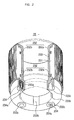
- the magnet 21 is located in the space between the outside and inside stators 22,23 and linearly reciprocates in an axial direction relative to the stators 22,23.
- the magnet 21 is connected to the piston 34 at an upper end thereof via a slide element 21 a, so that the piston linearly moves in the cylinder 32 when the magnet reciprocates.
- a resonant spring 24 similar to a kind of plate spring, is mounted to an upper end of the piston 34 to vibrate vertically. The resonant spring 24 enhances the linear moving action of the piston 34 in the cylinder 32.
- the thin metal plates 231 each have a plurality of locking embossments 232 at upper and lower portions thereof.
- the embossments 232 allow the thin metal plates 231 to be assembled with each other into a metal plate assembly.
- the embossments 232 maybe formed on each of the thin metal plates 231 through an appropriate machining process, such as a pressing process.
- Each of the embossments 232 thus has a protuberance 232a and a recess 232b on both sides of each of the thin metal plates 231.
- the protuberances 232a of a thin metal plate 231 is inserted into the recess 232b of a neighbouring thin metal plate 231 so that the overall metal plates 231 are assembled with each other into a metal sheet assembly.
- Each of the thin metal plates 231 have two locking notches 231a on each of the upper and lower edges thereof to lock the thin metal plates 231 to the holder 233 during an insert-molding process of forming the holder 233 using a resin material.
- the molten resin material fills the locking notches 231a formed at the upper and lower edges of the thin metal plates 231.
- the metal plates 231 are firmly held by the holder 233.
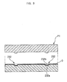
- the metal sheet O is subjected to a pressing process to form the embossments 232 by using a first press P1 which is an embossing press, as shown in Figure 3 .
- a first press P1 which is an embossing press
- each of the embossments 232 forms a protuberance 232a and a recess 232b on both sides of the metal sheet O.
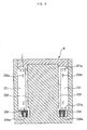
- the metal sheet O having the embossments 232 is, thereafter, cut into a plurality of pieces one by one to produce the thin metal plates 231, as shown in Figure 4 .
- the metal sheet O having the embossments 232 is fed to a second press P2 which is a cutting press to cut the metal sheet O into the pieces having a predetermined size.
- the thin metal plate 231 is layered on top of an uppermost thin metal plate of the metal plate assembly vertically placed at a position under the second press P2.
- each of the thin metal plates 231 is pushed downward by the second press P2 to be layered on top of the uppermost thin metal plate of the metal plate assembly, just after the thin metal plate 231 is cut from the metal sheet O by the second press P2.
- the thin metal plates 231 in the metal plate assembly are locked to each other by the embossments 232 thereof.
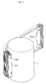
- the thin metal plates 231 which are arranged in the cylindrical arrangement are set in the mold M, and a molten resin material is injected into the cavity of the mold M having the thin metal plates 231, as shown in Figure 6 , thus forming the holder 233 which firmly holds the thin metal plates 231 in desired positions in the cylindrical arrangement.
- the inside stator 23 having the thin metal plates 231 is thus produced.
- the linear compressor of the present invention is produced and operated as follows.
- a molten resin material is injected into the cavity of the mold M and is hardened, thus forming the holder 233.
- the holder 233 covers the upper edges, inside edges and lower edges of the thin metal plates 231, thus firmly holding the thin metal plates 231 in desired positions in the cylindrical arrangement.
- the present invention provides a linear compressor and a method of producing the linear compressor.
- a linear compressor In an inside stator of a linear motor of the linear compressor, a plurality of thin metal plates which are arranged in a cylindrical arrangement are insert-molded to a holder that is made of a nonconductive resin material, so that the thin metal plates are prevented from being in electrical contact with each other. Therefore, the linear compressor does not generate eddy currents in the inside stator, and prevents an eddy current loss.
- the inside stator is fastened to a cylinder block by means of a fastening member, such as a setscrew, which passes through the cylinder block to be tightened to an internally-threaded hole of a locking member insert-molded to the holder. Therefore, work efficiency is improved during a process of producing the linear compressor.
- a fastening member such as a setscrew
Landscapes
- Engineering & Computer Science (AREA)
- Power Engineering (AREA)
- Manufacturing & Machinery (AREA)
- Compressor (AREA)
- Compressors, Vaccum Pumps And Other Relevant Systems (AREA)
- Iron Core Of Rotating Electric Machines (AREA)
- Reciprocating, Oscillating Or Vibrating Motors (AREA)
- Linear Motors (AREA)
- Manufacture Of Motors, Generators (AREA)
Claims (22)
- Stator für einen Linearkompressor, umfassend mehrere beabstandete Metallplatten (231), die in einem Kreis angeordnet sind, so dass jede Platte (231) in einer Ebene liegt, die eine Ebene jeder der anderen Platten (231) in einem gemeinsamen Punkt schneidet, gekennzeichnet durch einen sich in Umfangsrichtung erstreckenden Halter (233) der aus einem nicht leitenden Material gegossen ist, um die Platten (231) in Position zu halten, wobei der Halter (233) einen Basisteil (233a) aufweist und der Basisteil Mittel (234a) zum Anbauen des Halters (233) an einem Linearkompressor umfasst.
- Stator nach Anspruch 1, wobei sich der Halter (233) in Umfangsrichtung erstreckt.
- Stator nach Anspruch 1 oder Anspruch 2, wobei es sich bei dem nichtleitenden Material um ein Harz handelt.
- Stator nach einem der Ansprüche 1 bis 3, wobei der Halter (233) um die Platten (231) gegossen wird, nachdem die Platten (231) in der Position angeordnet worden sind.
- Stator nach einem der Ansprüche 1 bis 4, wobei jede Platte (231) einen oberen und einen unteren Rand aufweist, die von einem inneren Rand getrennt sind, wobei der obere, der untere und der innere Rand alle in dem Halter (233) aufgenommen sind.
- Stator nach einem der vorangehenden Ansprüche, umfassend eine Sperrkerbe (231a) an jeder Metallplatte (231), um sie an dem Halter (233) anzubringen.
- Stator nach einem der vorangehenden Ansprüche, wobei das Mittel zum Anbauen des Halters (233) an einem Linearkompressor ein Sperrelement (234) umfasst, das in dem Basisteil (233a) des Halters (233) angeordnet ist und an einem Ende desselben mit einem Innengewinde (234a) versehen ist.
- Stator nach Anspruch 7, wobei der Basisteil (233a) eine Ölnut (233b) umfasst, um Öl dadurch hindurch fließen zu lassen.
- Stator nach Anspruch 8, weiter umfassend einen Vorsprung (233c), der an dem Basisteil (233a) des Halters (233) vorgesehen ist, um den Halter (233) an einem Zylinderblock zu tragen, so dass ein Spalt zwischen dem Halter (233) und dem Zylinderblock definiert ist, wenn der Halter (233) daran angeordnet ist.
- Stator nach einem der vorangehenden Ansprüche, wobei jede Platte (231) eine Prägung (232) aufweist, die eine Erhebung (232a) auf einer Seite jeder Platte (231) und eine Vertiefung (232b) auf einer gegenüberliegenden Seite jeder Platte (231) bildet, so dass die Erhebung (232a) jeder Platte (231) in der Vertiefung (232b) einer benachbarten Platte (231) aufgenommen wird.
- Stator nach Anspruch 10, wobei jede Platte (231) mehrere Prägungen (232) umfasst, die entlang einer axialen Linie neben einem inneren Rand jeder Platte (231) gebildet sind, wenn die Platten (231) in Position angeordnet worden sind.
- Stator nach einem der vorangehenden Ansprüche, wobei jede beabstandete Platte (231) mit einem isolierenden Material bedeckt ist.
- Linearkompressor, umfassend einen Stator (23) nach einem der vorangehenden Ansprüche.
- Linearkompressor nach Anspruch 13, umfassend einen Zylinder (32), der eine Kammer mit einem gleitfähig darin aufgenommenen Kolben (34) und einen um den Zylinder (32) angeordneten Magneten (21) umfasst, wobei der Halter (233) an den Zylinder (32) angebaut ist.
- Linearkompressor nach Anspruch 14, wobei mindestens ein Abschnitt des Halters (233) von dem Zylinder (32) beabstandet ist.
- Verfahren zum Bilden eines Stators für einen Linearkompressor nach einem der Ansprüche 1 bis 12, umfassend die Schritte des Bildens einer Metallplattengruppe durch Nehmen mehrerer Metallplatten (231) und Verbinden derselben miteinander, bevor sie in eine kreisförmige Anordnung gebogen werden, so dass jede Platte (231) in einer Ebene liegt, die eine Ebene von jeder der anderen Platten (231) in einem gemeinsamen Punkt schneidet, gekennzeichnet durch Gießen eines nichtleitenden Materials um die Metallplattengruppe, um einen Halter zum Halten der Platten in der kreisförmigen Anordnung zu bilden, und Ausbilden des Halters (233) dazu, einen Basisteil (233a) mit Mitteln (234a) zum Anbauen des Halters (233) an einem Linearkompressor aufzuweisen.
- Verfahren nach Anspruch 16, weiter umfassend die Schritte des Bildens einer Prägung an jeder Metallplatte (231) mit einer Erhebung (232a) auf einer Seite jeder Platte (231) und eine Vertiefung (232b) auf einer gegenüberliegenden Seite und Verbinden der mehreren Platten miteinander, indem die Erhebung (232a) jeder Platte (231) in der Vertiefung (232b) einer benachbarten Platte (231) aufgenommen wird.
- Verfahren nach Anspruch 17, weiter umfassend den Schritt des Herstellens jeder Platte (231) durch Schneiden in einem Pressprozess, nachdem die Prägung daran gebildet wird.
- Verfahren nach Anspruch 18, weiter umfassend den Schritt des Schichtens der mehreren Platten (231) aufeinander, nachdem die Platten (231) geschnitten werden und vor dem Zusammenbau.
- Verfahren nach Anspruch 19, weiter umfassend den Schritt des Biegens der Platten zu einer kreisförmigen Anordnung unter Verwendung einer zylindrischen Hilfsvorrichtung, um die die Platten gebogen werden.
- Verfahren nach Anspruch 20, weiter umfassend den Schritt des Biegesperrens der Erhebung jeder Platte in der Vertiefung der daneben liegenden Platte.
- Verfahren nach Anspruch 16, weiter umfassend die Schritte des Anordnens der Metallplattengruppe in einem Formwerkzeug mit einer Höhlung und Einspritzen von geschmolzenem Harz in die Höhlung, um das nichtleitende Material um die Metallplattengruppe zu gießen.
Applications Claiming Priority (4)
| Application Number | Priority Date | Filing Date | Title |
|---|---|---|---|
| KR2003040275 | 2003-06-20 | ||
| KR20030040275 | 2003-06-20 | ||
| KR1020030046421A KR100919405B1 (ko) | 2003-06-20 | 2003-07-09 | 리니어 압축기 및 그 제조방법 |
| KR2003046421 | 2003-07-09 |
Publications (3)
| Publication Number | Publication Date |
|---|---|
| EP1489720A2 EP1489720A2 (de) | 2004-12-22 |
| EP1489720A3 EP1489720A3 (de) | 2006-11-08 |
| EP1489720B1 true EP1489720B1 (de) | 2013-10-23 |
Family
ID=33422299
Family Applications (1)
| Application Number | Title | Priority Date | Filing Date |
|---|---|---|---|
| EP04251770.6A Expired - Lifetime EP1489720B1 (de) | 2003-06-20 | 2004-03-26 | Linearkompressor |
Country Status (4)
| Country | Link |
|---|---|
| US (2) | US7413420B2 (de) |
| EP (1) | EP1489720B1 (de) |
| JP (1) | JP3970858B2 (de) |
| CN (1) | CN100595437C (de) |
Families Citing this family (14)
| Publication number | Priority date | Publication date | Assignee | Title |
|---|---|---|---|---|
| JP3579416B1 (ja) * | 2003-06-16 | 2004-10-20 | シャープ株式会社 | リニアモータ装置およびその製造方法、リニア圧縮機ならびにスターリング機関 |
| KR100520072B1 (ko) * | 2003-06-19 | 2005-10-11 | 삼성전자주식회사 | 리니어 압축기 |
| KR20050049269A (ko) * | 2003-11-21 | 2005-05-25 | 삼성광주전자 주식회사 | 리니어 압축기 |
| KR20050101484A (ko) * | 2004-04-19 | 2005-10-24 | 삼성광주전자 주식회사 | 리니어 압축기 |
| KR100624733B1 (ko) * | 2005-05-06 | 2006-09-15 | 엘지전자 주식회사 | 리니어 모터의 아우터 코어 조립구조 |
| JP5273084B2 (ja) | 2010-03-31 | 2013-08-28 | 株式会社豊田自動織機 | 電動圧縮機 |
| CN103790799A (zh) * | 2012-11-02 | 2014-05-14 | 海尔集团公司 | 线性压缩机 |
| EP2919366B1 (de) * | 2012-11-07 | 2020-10-28 | Qingdao Haier Smart Technology R&D Co., Ltd. | Stator für einen linearverdichter und fixierverfahren dafür, lineare elektrische maschine und linearverdichter |
| CN103835912B (zh) * | 2012-11-26 | 2016-12-21 | 青岛海尔智能技术研发有限公司 | 线性压缩机 |
| US9518572B2 (en) * | 2014-02-10 | 2016-12-13 | Haier Us Appliance Solutions, Inc. | Linear compressor |
| US9322401B2 (en) * | 2014-02-10 | 2016-04-26 | General Electric Company | Linear compressor |
| CN108453187B (zh) * | 2017-12-29 | 2024-09-10 | 瑞立集团瑞安汽车零部件有限公司 | 一种锥面定位快速自动翻铆成型干燥筒总成装配夹具 |
| CN111668946A (zh) * | 2020-05-11 | 2020-09-15 | 江苏铱莱德驱动系统有限公司 | 一种圆筒型直线电机的定子结构 |
| CN112555123B (zh) * | 2020-12-10 | 2023-06-02 | 武汉高芯科技有限公司 | 可维持活塞平衡位置不变的直线压缩机 |
Citations (2)
| Publication number | Priority date | Publication date | Assignee | Title |
|---|---|---|---|---|
| WO2001061831A1 (en) * | 2000-02-17 | 2001-08-23 | Lg Electronics Inc. | Reciprocating motor |
| US20030102763A1 (en) * | 2001-10-22 | 2003-06-05 | Kyeong-Bae Park | Stator for reciprocating motor and manufacturing method thereof |
Family Cites Families (11)
| Publication number | Priority date | Publication date | Assignee | Title |
|---|---|---|---|---|
| US2179057A (en) * | 1937-05-03 | 1939-11-07 | United States Gypsum Co | Heat insulation |
| US2193141A (en) * | 1937-08-23 | 1940-03-12 | Pacific Nat Bank Of Seattle | Heating system for supercharged cabins |
| US3883629A (en) * | 1968-12-31 | 1975-05-13 | Ici Ltd | Injection molding of laminar articles having a foam core and an integral skin |
| US3947155A (en) * | 1974-09-19 | 1976-03-30 | Tecumseh Products Company | Linear compressor |
| US4083221A (en) * | 1976-07-29 | 1978-04-11 | Duffy Tool & Stamping, Inc. | Parts forming apparatus and method |
| KR100206849B1 (ko) | 1996-12-31 | 1999-07-01 | 구자홍 | 리니어 압축기용 철심적층의 제조방법 |
| US6077054A (en) * | 1997-12-23 | 2000-06-20 | Samsung Electronics Co., Ltd. | Stator of linear compressor |
| JP3083518B2 (ja) * | 1998-07-03 | 2000-09-04 | 三星電子株式会社 | リニア圧縮機の内側コア及びシリンダブロックの構造並びに結合方法 |
| BR0106730A (pt) * | 2000-02-17 | 2002-05-14 | Lg Eletronics Inc | Estrutura para estator de motor com induzido oscilante |
| US6838789B2 (en) | 2001-10-26 | 2005-01-04 | Lg Electronics Inc. | Reciprocating motor |
| CN1159828C (zh) | 2001-12-21 | 2004-07-28 | 叶天启 | 叠铆式连接的电机铁芯 |
-
2004
- 2004-03-04 US US10/792,630 patent/US7413420B2/en not_active Expired - Lifetime
- 2004-03-12 CN CN200410039643A patent/CN100595437C/zh not_active Expired - Fee Related
- 2004-03-23 JP JP2004085315A patent/JP3970858B2/ja not_active Expired - Fee Related
- 2004-03-26 EP EP04251770.6A patent/EP1489720B1/de not_active Expired - Lifetime
-
2007
- 2007-08-13 US US11/889,402 patent/US7788804B2/en not_active Expired - Lifetime
Patent Citations (2)
| Publication number | Priority date | Publication date | Assignee | Title |
|---|---|---|---|---|
| WO2001061831A1 (en) * | 2000-02-17 | 2001-08-23 | Lg Electronics Inc. | Reciprocating motor |
| US20030102763A1 (en) * | 2001-10-22 | 2003-06-05 | Kyeong-Bae Park | Stator for reciprocating motor and manufacturing method thereof |
Also Published As
| Publication number | Publication date |
|---|---|
| US7413420B2 (en) | 2008-08-19 |
| US20080016687A1 (en) | 2008-01-24 |
| EP1489720A2 (de) | 2004-12-22 |
| CN100595437C (zh) | 2010-03-24 |
| US7788804B2 (en) | 2010-09-07 |
| CN1573094A (zh) | 2005-02-02 |
| US20040258543A1 (en) | 2004-12-23 |
| EP1489720A3 (de) | 2006-11-08 |
| JP3970858B2 (ja) | 2007-09-05 |
| JP2005009482A (ja) | 2005-01-13 |
Similar Documents
| Publication | Publication Date | Title |
|---|---|---|
| US7788804B2 (en) | Linear compressor and method of producing the same | |
| JP3802491B2 (ja) | 往復動式モータ | |
| KR100556800B1 (ko) | 왕복동식 압축기의 내측고정자 고정장치 | |
| JP4546476B2 (ja) | 往復動式圧縮機のモータ固定子固定装置及びその固定方法 | |
| US7385319B2 (en) | Motor fixing structure of reciprocating compressor | |
| EP1681756B1 (de) | Stator eines Hubkolbenkompressors | |
| US7294941B2 (en) | Winding coil assembly of reciprocating motor and manufacturing method thereof | |
| KR100355671B1 (ko) | 리니어 압축기의 내측코어와 실린더블록의 구조와 결합방법 | |
| CN1894840B (zh) | 往复式电机的定子及其制造方法 | |
| KR100414081B1 (ko) | 리니어압축기의모터고정자제조방법 | |
| KR100919405B1 (ko) | 리니어 압축기 및 그 제조방법 | |
| KR100520072B1 (ko) | 리니어 압축기 | |
| KR100615798B1 (ko) | 리니어 압축기의 이너스테이터 고정구조 | |
| KR100543327B1 (ko) | 리니어 압축기 | |
| KR100608695B1 (ko) | 왕복동식 압축기의 내측고정자 고정 구조 | |
| EP1676351A1 (de) | Ringförmiger stapel von laminationselementen | |
| EP1518312A1 (de) | Verfahren zur formung des stators eines linearmotors, ringförmiger stapel von blechpaket-elementen und stator für einen elektrischen motor | |
| KR100444952B1 (ko) | 리니어 압축기 및 리니어 압축기용 고정자의 제조방법 | |
| US20040223861A1 (en) | Linear compressor | |
| KR19980050606A (ko) | 리니어 압축기의 모터구조 | |
| KR19980059788A (ko) | 리니어 압축기용 철심적층의 제조방법 |
Legal Events
| Date | Code | Title | Description |
|---|---|---|---|
| PUAI | Public reference made under article 153(3) epc to a published international application that has entered the european phase |
Free format text: ORIGINAL CODE: 0009012 |
|
| AK | Designated contracting states |
Kind code of ref document: A2 Designated state(s): AT BE BG CH CY CZ DE DK EE ES FI FR GB GR HU IE IT LI LU MC NL PL PT RO SE SI SK TR |
|
| AX | Request for extension of the european patent |
Extension state: AL LT LV MK |
|
| PUAL | Search report despatched |
Free format text: ORIGINAL CODE: 0009013 |
|
| AK | Designated contracting states |
Kind code of ref document: A3 Designated state(s): AT BE BG CH CY CZ DE DK EE ES FI FR GB GR HU IE IT LI LU MC NL PL PT RO SE SI SK TR |
|
| AX | Request for extension of the european patent |
Extension state: AL LT LV MK |
|
| 17P | Request for examination filed |
Effective date: 20070327 |
|
| AKX | Designation fees paid |
Designated state(s): DE DK FR GB IT |
|
| 17Q | First examination report despatched |
Effective date: 20090807 |
|
| RAP1 | Party data changed (applicant data changed or rights of an application transferred) |
Owner name: SAMSUNG ELECTRONICS CO., LTD. |
|
| REG | Reference to a national code |
Ref country code: DE Ref legal event code: R079 Ref document number: 602004043623 Country of ref document: DE Free format text: PREVIOUS MAIN CLASS: H02K0001180000 Ipc: H02K0001140000 |
|
| RIC1 | Information provided on ipc code assigned before grant |
Ipc: H02K 15/02 20060101ALI20130301BHEP Ipc: H02K 1/18 20060101ALI20130301BHEP Ipc: H02K 33/16 20060101ALI20130301BHEP Ipc: H02K 1/14 20060101AFI20130301BHEP |
|
| GRAP | Despatch of communication of intention to grant a patent |
Free format text: ORIGINAL CODE: EPIDOSNIGR1 |
|
| INTG | Intention to grant announced |
Effective date: 20130527 |
|
| GRAS | Grant fee paid |
Free format text: ORIGINAL CODE: EPIDOSNIGR3 |
|
| GRAA | (expected) grant |
Free format text: ORIGINAL CODE: 0009210 |
|
| AK | Designated contracting states |
Kind code of ref document: B1 Designated state(s): DE DK FR GB IT |
|
| REG | Reference to a national code |
Ref country code: GB Ref legal event code: FG4D |
|
| REG | Reference to a national code |
Ref country code: DE Ref legal event code: R096 Ref document number: 602004043623 Country of ref document: DE Effective date: 20131219 |
|
| REG | Reference to a national code |
Ref country code: DE Ref legal event code: R097 Ref document number: 602004043623 Country of ref document: DE |
|
| PLBE | No opposition filed within time limit |
Free format text: ORIGINAL CODE: 0009261 |
|
| STAA | Information on the status of an ep patent application or granted ep patent |
Free format text: STATUS: NO OPPOSITION FILED WITHIN TIME LIMIT |
|
| PG25 | Lapsed in a contracting state [announced via postgrant information from national office to epo] |
Ref country code: DK Free format text: LAPSE BECAUSE OF FAILURE TO SUBMIT A TRANSLATION OF THE DESCRIPTION OR TO PAY THE FEE WITHIN THE PRESCRIBED TIME-LIMIT Effective date: 20131023 |
|
| 26N | No opposition filed |
Effective date: 20140724 |
|
| REG | Reference to a national code |
Ref country code: DE Ref legal event code: R119 Ref document number: 602004043623 Country of ref document: DE |
|
| REG | Reference to a national code |
Ref country code: DE Ref legal event code: R097 Ref document number: 602004043623 Country of ref document: DE Effective date: 20140724 |
|
| REG | Reference to a national code |
Ref country code: DE Ref legal event code: R119 Ref document number: 602004043623 Country of ref document: DE Effective date: 20141001 |
|
| PG25 | Lapsed in a contracting state [announced via postgrant information from national office to epo] |
Ref country code: DE Free format text: LAPSE BECAUSE OF NON-PAYMENT OF DUE FEES Effective date: 20141001 |
|
| REG | Reference to a national code |
Ref country code: FR Ref legal event code: PLFP Year of fee payment: 13 |
|
| REG | Reference to a national code |
Ref country code: FR Ref legal event code: PLFP Year of fee payment: 14 |
|
| REG | Reference to a national code |
Ref country code: FR Ref legal event code: PLFP Year of fee payment: 15 |
|
| PGFP | Annual fee paid to national office [announced via postgrant information from national office to epo] |
Ref country code: GB Payment date: 20180222 Year of fee payment: 15 |
|
| PGFP | Annual fee paid to national office [announced via postgrant information from national office to epo] |
Ref country code: FR Payment date: 20180222 Year of fee payment: 15 Ref country code: IT Payment date: 20180312 Year of fee payment: 15 |
|
| GBPC | Gb: european patent ceased through non-payment of renewal fee |
Effective date: 20190326 |
|
| PG25 | Lapsed in a contracting state [announced via postgrant information from national office to epo] |
Ref country code: GB Free format text: LAPSE BECAUSE OF NON-PAYMENT OF DUE FEES Effective date: 20190326 |
|
| PG25 | Lapsed in a contracting state [announced via postgrant information from national office to epo] |
Ref country code: IT Free format text: LAPSE BECAUSE OF NON-PAYMENT OF DUE FEES Effective date: 20190326 Ref country code: FR Free format text: LAPSE BECAUSE OF NON-PAYMENT OF DUE FEES Effective date: 20190331 |