EP1489486A2 - Automatic tab displaying and maximum tab storing user interface and a reprographic machine having same - Google Patents
Automatic tab displaying and maximum tab storing user interface and a reprographic machine having same Download PDFInfo
- Publication number
- EP1489486A2 EP1489486A2 EP04253598A EP04253598A EP1489486A2 EP 1489486 A2 EP1489486 A2 EP 1489486A2 EP 04253598 A EP04253598 A EP 04253598A EP 04253598 A EP04253598 A EP 04253598A EP 1489486 A2 EP1489486 A2 EP 1489486A2
- Authority
- EP
- European Patent Office
- Prior art keywords
- tab
- selection
- displaying
- tabs
- display area
- Prior art date
- Legal status (The legal status is an assumption and is not a legal conclusion. Google has not performed a legal analysis and makes no representation as to the accuracy of the status listed.)
- Withdrawn
Links
Images


Classifications
-
- G—PHYSICS
- G06—COMPUTING OR CALCULATING; COUNTING
- G06F—ELECTRIC DIGITAL DATA PROCESSING
- G06F3/00—Input arrangements for transferring data to be processed into a form capable of being handled by the computer; Output arrangements for transferring data from processing unit to output unit, e.g. interface arrangements
- G06F3/01—Input arrangements or combined input and output arrangements for interaction between user and computer
- G06F3/048—Interaction techniques based on graphical user interfaces [GUI]
- G06F3/0481—Interaction techniques based on graphical user interfaces [GUI] based on specific properties of the displayed interaction object or a metaphor-based environment, e.g. interaction with desktop elements like windows or icons, or assisted by a cursor's changing behaviour or appearance
- G06F3/0483—Interaction with page-structured environments, e.g. book metaphor
Definitions
- the at least second display area has (i) a second surface size less than a sum total of each of the first surface size of each of the selection tabs, (ii) a first display portion for displaying a first set of the selection tabs in an open mode showing fully a visible outline and identification markings of each tab in the first set, and (iii) at least a second display portion for displaying at least a second set of the selection tabs in a folded mode showing only part of the visible outline of each tab in the at least second set.
- the digital machine 100 includes a scanning device 102, a printing module 104, and the automatic tab displaying and maximum tab storing UI assembly 150 (to be described in detail below).
- the digital machine 100 may also include a finisher device 106 which may be a sorter, tower mailbox or stapler, and at least an electronic subsystem (ESS) controller 110 for controlling all the features and functions of the machine 100.
- the printing module 104 may include a plurality of paper trays 112 that store paper used in the printing process.
- the digital machine may include a high capacity feeder 116 which is capable of holding large amounts of paper stock to be used by the machine.
- the printing module 104 would retrieve the proper paper from one of the multiple paper trays 112 or the high capacity feeder 116, render the desired image on the retrieved paper, and output the printed image to the finishing device 106 for further operations.
- FIG. 2 An example of the basic architecture of the digital machine 100 is illustrated as a block diagram in detail in FIG. 2, and includes the scanner 102 which converts an original image into a set of digital signals that can be either stored or reproduced.
- the scanner 102 is connected to a central bus system 120 which may be either a single bus or a plurality of buses which provide interconnections and intercommunications between the various modules and stations on the digital machine.
- the automatic tab displaying and maximum tab storing UI assembly 150 includes a display screen 152 for displaying user dialog information 154. It also includes a series of machine process control and user interactive functional features shown generally as 156, for operator access, and for controlling operation of the machine 100. An associated controller such as the ESS 110 is connected to and forms part of the automatic tab displaying and maximum tab storing UI assembly 150.
- the at least second display area 250 also includes at least a second display portion 254 for displaying at least a second set T2 of the screen selection tabs 214, 224, 234 for example in a folded mode M2 showing only part of the markings 218, 228, 238 for example and part of the visible outline 216, 226, 236 for example of each tab in the at least second set T2.
- the at least second display area 250 further has at least a third display portion 256 for displaying, in full first surface size, at least one selection tab 214, 224, 234 for example of at least one screen 210, 220, 230 for example of the plural selectable screens, such that the at least one screen 210, 220, 230 for example is displayed in the first display area 240.
- each screen selection tab 214, 224, 234 for example is located relative to an edge, for example the top edge E1, of its selectable screen 210, 220, 230, and is movable from one end E2 towards the other end E3 of the screen along such edge E1.
- the automatic tab displaying and maximum tab storing UI assembly also includes a programmable controller assembly that is connected to the display device and includes a tab manipulator for automatically moving the selection tabs in the at least second display area in a first direction from the open mode towards the folded mode, and in a second direction from the folded mode towards the open mode; thereby enabling the at least second display area to contain and intuitively fully display more selection tabs than can ordinarily be fully displayed within the second display area.
Landscapes
- Engineering & Computer Science (AREA)
- General Engineering & Computer Science (AREA)
- Theoretical Computer Science (AREA)
- Human Computer Interaction (AREA)
- Physics & Mathematics (AREA)
- General Physics & Mathematics (AREA)
- User Interface Of Digital Computer (AREA)
- Facsimiles In General (AREA)
- Accessory Devices And Overall Control Thereof (AREA)
Abstract
Description
- The present invention is directed to user interfaces (UI's), and more specifically, to an automatic tab displaying and maximum tab storing user interface assembly as well as reprographic machine having same.
One example of a conventional reprographic machine is the office copier. Traditionally, the copier, in the office equipment context, refers to a light lens xerographic copier in which paper originals are in fact photographed. The images are focused on an area of a photoreceptor, which is subsequently developed with toner. The developed image on the photoreceptor is then transferred to a copy sheet that in turn is used to create a permanent copy of the original. - In recent years, however, there has been made available what is known as digital copiers or printing machines. In the most basic functions, a digital copier or printing machine performs the same functions as a light lens copier, except that it includes a programmable controller for controlling its functions, and the original image to be copied is not directly focused on a photoreceptor. Instead, with a digital copier or printer, the original image is received, for example, from a personal computer (PC) work station, or storage media, or is scanned by a device generally known as a raster input scanner (RIS) that is typically in the form of a linear array of small photosensors. The controller further enables a wide range of image manipulation and processing capabilities.
- The original image received as such is focused on the photosensors in the RIS. The photosensors convert the various light and dark areas of the original image to a set of digital signals. These digital signals are temporarily retained in a memory and then eventually are further processed, and manipulated/and or used as is, with the aid of a user interface (UI) assembly, to operate the digital printing machine or copier when it is desired to print copies of the original. The digital signals may also be sent directly to the digital printing machine or copier without being stored in a memory. Typically however, each such digital printing machine or copier includes a user interface (UI) having an array of features.
- User interfaces (UI's) on such digital printing machines or copiers typically utilize LCD's or full screen displays with graphics that include selectable objects in the form of buttons, icons, tabs, and file folders for example. With particular reference to the tabs, because tabs need to include text markings which require space for identification, only a limited number of tabs, say 4 to 6 on a half screen UI display, and 8-10 on a full screen display, can be shown across the screen display in a single row of such tabs. Unfortunately however, the proliferation and increasing number of new features on such imaging machines has created a need for more and more tabs which would mean a need for more than say 4 to 6 on a half screen UI display, and 8-10 on a full screen display. Conventional solutions have displayed multiple rows of tabs, but this reduces the available space on the screen; others use a "more tabs" button (perhaps with a "back" button) which displays a new set of tabs over the top of the original set, but this is cumbersome and unintuitive.
- In accordance with the present invention, there is provided an automatic tab displaying and maximum tab storing UI assembly for use on a digital imaging machine. The automatic tab displaying and maximum tab storing UI assembly includes a display device having (i) a plurality of selectable screens each having a different user interactive information set and a screen selection tab that has a visible outline, a first surface size, and tab identification markings; (ii) a first display area for displaying at least one screen of the plurality of selectable screens; and (iii) at least a second display area for containing all the selection tabs of the plurality of selectable screens. The at least second display area has (i) a second surface size less than a sum total of each of the first surface size of each of the selection tabs, (ii) a first display portion for displaying a first set of the selection tabs in an open mode showing fully a visible outline and identification markings of each tab in the first set, and (iii) at least a second display portion for displaying at least a second set of the selection tabs in a folded mode showing only part of the visible outline of each tab in the at least second set. The automatic tab displaying and maximum tab storing UI assembly also includes a programmable controller assembly that is connected to the display device and includes a tab manipulator for automatically moving the selection tabs in the at least second display area in a first direction from the open mode towards the folded mode, and in a second direction from the folded mode towards the open mode; thereby enabling the at least second display area to contain and intuitively fully display more selection tabs than can ordinarily be fully displayed within the second display area.
- The following is a brief description of the drawings used to describe the present invention, and thus, these drawings are being presented for illustrative purposes only and thus should not limit the scope of the present invention, wherein:
- FIG. 1 is an illustration of a reprographic machine including the automatic tab displaying and maximum tab storing UI assembly in accordance with the present invention;
- FIG. 2 is a block diagram illustration of the reprographic machine of FIG. 1;
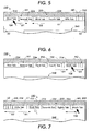
- FIG.3 is a first illustration of the automatic tab displaying and maximum tab storing UI assembly of the present invention showing the first tab selected and tabs in the rightmost area folded;
- FIG. 4 is a second illustration of the automatic tab displaying and maximum tab storing UI assembly of the present invention the sixth previously folded tab in the folded rightmost area about to be selected;
- FIG. 5 is a third illustration of the automatic tab displaying and maximum tab storing UI assembly of the present invention showing the sixth tab selected and tabs in the leftmost area folded;
- FIG. 6 is a fourth illustration of the automatic tab displaying and maximum tab storing UI assembly of the present invention showing fully displayed, partially displayed, and outline-only tabs to the right; and
- FIG. 7 is a fifth illustration of the automatic tab displaying and maximum tab storing UI assembly of the present invention showing fully displayed, partially displayed, and outline-only tabs to the left.
-
- Referring now to FIGS. 1-2, an overall construction, and a block diagram, of a digital
reprographic machine 100 including the automatic tab displaying and maximum tab storingUI assembly 150 of the present invention, are illustrated. As shown, thedigital machine 100 includes ascanning device 102, aprinting module 104, and the automatic tab displaying and maximum tab storing UI assembly 150 (to be described in detail below). Thedigital machine 100 may also include afinisher device 106 which may be a sorter, tower mailbox or stapler, and at least an electronic subsystem (ESS)controller 110 for controlling all the features and functions of themachine 100. Theprinting module 104 may include a plurality ofpaper trays 112 that store paper used in the printing process. Lastly, the digital machine may include a high capacity feeder 116 which is capable of holding large amounts of paper stock to be used by the machine. - In a typical scanning function, the operator would utilize the
scanning device 102 to scan in the images from the original documents. Thisscanning device 102 may be a platen type scanner or may include a constant velocity transport system which moves the original documents across a stationary scanning device. Moreover, thescanning device 102 may also include a document handling system which is capable of placing the original documents, automatically, on the glass platen for scanning. - With respect to the printing functions, the
printing module 104 would retrieve the proper paper from one of themultiple paper trays 112 or the high capacity feeder 116, render the desired image on the retrieved paper, and output the printed image to thefinishing device 106 for further operations. - An example of the basic architecture of the
digital machine 100 is illustrated as a block diagram in detail in FIG. 2, and includes thescanner 102 which converts an original image into a set of digital signals that can be either stored or reproduced. Thescanner 102 is connected to acentral bus system 120 which may be either a single bus or a plurality of buses which provide interconnections and intercommunications between the various modules and stations on the digital machine. - The
digital machine 100 also includes adigital printing device 122 of the printing module 104 (FIG. 2) which converts digital signals representing an image into a hardcopy of that image on a recording medium whether the recording medium be paper, transparency, or other type of markable medium. Afirst memory device 124 is provided for storing a variety of types of digital information such as machine fault information, machine history information, digital images to be processed at a later time, instruction sets for the machine or job instruction sets. A second memory device forming an electronicpre-collation memory section 126 may be provided for storing the digital representation of the image being presently rendered by thedigital printing device 122. In the electronicpre-collation memory 126, the digital image is already laid out in its page structure so that it can be readily rendered by thedigital printing device 122. - Since the
digital machine 100 may be connected to a network including a PC work station (not shown), it includes anetwork interface 128 and anadditional controller 130 which control the interrelationship between the various modules or stations on thedigital machine 100 and the network. - In cases where the
digital machine 100 is a multi-function machine, it would include, typically, a voice/data modem 132 and atelephone circuit board 134. Moreover, the digital machine may also include input/output drives 136 such as a floppy disc drive, a CD ROM drive, a tape drive, or other type of drive which can accept a portable memory device. - Referring now to FIGS. 1-7, the
digital machine 100, in accordance with the present invention, includes the automatic tab displaying and maximum tab storingUI assembly 150 for maximizing tabbed machine features and making tab selection and display intuitive. The automatic tab displaying and maximum tab storingUI assembly 150 with the aid of thecontroller 110, effectively enables the user to control, at the machine, a relatively larger array of machine features as well as various functions of the digital machine by storing and intuitively as well as automatically presenting a large number of tabbed informational screens to the user. - Referring in particular to FIGS. 6-7, the automatic tab displaying and maximum tab storing
UI assembly 150 includes adisplay screen 152 for displayinguser dialog information 154. It also includes a series of machine process control and user interactive functional features shown generally as 156, for operator access, and for controlling operation of themachine 100. An associated controller such as the ESS 110 is connected to and forms part of the automatic tab displaying and maximum tab storingUI assembly 150. - The
display screen 152 is any suitable display screen that may be controlled by a point and clickdevice 158, it can be a touch sensitive video screen. The point and clickdevice 158 for example is a mouse. The series of machine process control and user interactive functional features 156 as illustrated include frequently used and well known machine functional features such as (a) color mode (auto, color, black and white); (b) sides imaged (1 to 1; 1 to 2; 2 to 2; and 2 to 1); (c) paper supply (auto,tray 1,tray 2,tray 3,tray 4, tray 5); (d) reduce/enlarge (auto, 100%, 50%, 64%[17" to 11"], 78%[14" to 11"]; and (e) copy output (collated, stapled, uncollated). - Referring in particular to FIGS. 3-7, the automatic tab displaying and maximum tab storing
UI assembly 150 as illustrated includes adisplay device 152 having a plurality of selectable screens, 210 (shown), each having a different user interactive information set 154 for example (FIGS. 6-7), and ascreen selection tab visible outline tab identification markings display device 152 also has afirst display area 240 for displaying at least one screen 210 (shown) of the plurality of selectable screens, and at least asecond display area 250 for containing all thescreen selection tabs - The at least
second display area 250 has a second surface size S2 that is less than a sum total of each of the first surface size S1 of each of theselection tabs second display area 250 also has a first display portion 252 for displaying a first set T1 of theselection tabs second display area 250 also includes at least a second display portion 254 for displaying at least a second set T2 of thescreen selection tabs markings visible outline second display area 250 further has at least a third display portion 256 for displaying, in full first surface size, at least oneselection tab screen 210, 220, 230 for example of the plural selectable screens, such that the at least onescreen 210, 220, 230 for example is displayed in thefirst display area 240. - The automatic tab displaying and maximum tab storing
UI assembly 150 also includes theprogrammable controller assembly 110 connected to thedisplay device 200 and having tab manipulation means 114 (FIG. 2) for automatically moving thescreen selection tabs second display area 250 in a first direction D1 (FIGS. 5-7) from the open mode M1 towards the folded mode M2, and in a second direction D2 from the folded mode M2 towards the open mode M1, thereby enabling the at leastsecond display area 250 to contain and intuitively fully displaymore selection tabs - The
identification markings selection tab second display area 250 includes a transition or third portion 256 within which in going from the at least second portion 254 to the first portion 252,selection tabs more outline second display area 250, adjacent selection tabs move by sliding over and under each other respectively. The tab manipulation means 114 include tab selection means and apointing device 158. - Still referring to FIGS. 3-7, the at least
second display area 250 comprises a vertically narrow and horizontally elongate area. Theselection tabs adjacent selection tabs selection tabs visible outline selection tab screen selection tab selectable screen 210, 220, 230, and is movable from one end E2 towards the other end E3 of the screen along such edge E1. - All
selection tabs second display area 250 comprise a row. In the UI assembly of the present invention, after selection of at least oneselection tab selection tab other selection tabs second display area 250. - The use of the automatic tab displaying and maximum tab storing
UI assembly 150 of the present invention effectively enables and allows easy, intuitive access to a larger set of tabs than could ordinarily fit in the same space with present designs. This will allow for the fitting of more features on machines with space constrained UI's, and hence enable products with greater and greater feature richness. Notice that only about five tabs can be comfortably fitted in the single row of tabs displayed for the half screen display, and perhaps seven for the full screen display. Thefirst tab other tabs most tabs visible tabs - Should the user need to access
tabs text 238 for example is not visible, the user merely touches moves the pointer of a mouse for example (or clicks with the mouse or other pointer device, depending on the technology used) on the hot or folded area M1 on the overlapped tabs at the right most area. If a touch system is used, the first tab of the next set of tabs is placed in front for the half screen. When selected, the selectedtab tab screen 210, 220, 230 fully showing. - Immediately upon coming to the top and opening, the selected
tab tabs tab tabs tab right tab tab - To make one of the now partially occluded and folded tabs in the left most area a selected tab, the process as described above with respect to the right most area, is reversed. The user therefore starts by selecting such tab from the collapsed tabs in the left most area.
- This is better than the alternative multiple tab designs because it allows the user to have all the tabs accessible in a fully open mode M1, partially open mode M3, and outline-only or folded mode M2, in a single row on the UI screen. The
tabs UI assembly 150 as such makes theUI display screen 210, 220, 230 for example more appealing to the user and intuitively more functional, without taking up a huge amount of real estate space on the local, embedded and web user interfaces. - As can be seen, there has been provided an automatic tab displaying and maximum tab storing UI assembly for use on a digital imaging machine. The automatic tab displaying and maximum tab storing UI assembly includes a display device having (i) a plurality of selectable screens each having a different user interactive information set and a screen selection tab that has a visible outline, a first surface size, and tab identification markings; (ii) a first display area for displaying at least one screen of the plurality of selectable screens; and (iii) at least a second display area for containing all the selection tabs of the plurality of selectable screens. The at least second display area has (i) a second surface size less than a sum total of each of the first surface size of each of the selection tabs, (ii) a first display portion for displaying a first set of the selection tabs in an open mode showing fully a visible outline and identification markings of each tab in the first set, and (iii) at least a second display portion for displaying at least a second set of the selection tabs in a folded mode showing only part of the visible outline of each tab in the at least second set. The automatic tab displaying and maximum tab storing UI assembly also includes a programmable controller assembly that is connected to the display device and includes a tab manipulator for automatically moving the selection tabs in the at least second display area in a first direction from the open mode towards the folded mode, and in a second direction from the folded mode towards the open mode; thereby enabling the at least second display area to contain and intuitively fully display more selection tabs than can ordinarily be fully displayed within the second display area.
- The identification markings of each selection tab include descriptive text information. The at least second display area includes a transition portion within which in going from the at least second portion to the first portion, selection tabs show more and more of the first surface size thereof of each, and more and more outline of each selection tab therein.
Claims (10)
- An automatic tab displaying and maximum tab storing UI assembly comprising:(a) a display device including:(i) a plurality of selectable screens each having a different user interactive information set and a screen selection tab, each said screen selection tab having a visible outline, a first surface size, and tab identification markings;(ii) a first display area for displaying at least one screen of said plurality of selectable screens; and(iii) at least a second display area for containing all said selection tabs of said plurality of selectable screens, said at least second area having (x) a second surface size less than a sum total of each of said first surface size of each of said selection tabs, (y) a first display portion for displaying a first set of said selection tabs in an open mode showing fully a visible outline and identification markings of each tab in said first set, and (z) at least a second display portion for displaying at least a second set of said selection tabs in a folded mode showing only part of said visible outline of each tab in said at least second set; and(b) a programmable controller assembly connected to said display device and including tab manipulation means, said tab manipulation means being programmed for automatically moving said selection tabs in said at least second display area in a first direction from said open mode towards said folded mode, and in a second direction from said folded mode towards said open mode; thereby enabling said at least second display area to contain and intuitively fully display more selection tabs than can ordinarily be fully displayed therein.
- The UI assembly of claim 1, wherein said at least second display area has at least a third portion for displaying, in full first surface size, at least one selection tab of at least one screen of said plurality of selectable screens, said at least one screen being displayed in said first display area.
- The UI assembly of claim 2, wherein after selection of at least one selection tab of said at least one screen, said at least third portion overlays and partially hides a part of said first portion..
- The UI assembly of claim 2 or claim 3, wherein said at least one selection tab displayed in said at least third portion is ocludable by any other selection tabs being moved by said manipulation means within said at least second display area.
- The UI assembly of any of the preceding claims, wherein said at least second display area includes a transition portion within which in going from said at least second portion to said first portion, selection tabs show more and more of said first surface size thereof of each, and more and more outline of each selection tab therein.
- The UI assembly of any of the preceding claims, wherein in said at least second display area, adjacent selection tabs move by sliding over and under each other respectively.
- The UI assembly of any of the preceding claims, wherein selection tabs, located further and further away within said at least second portion from said first portion, are overlapped to a greater and greater degree by adjacent selection tabs than are selection tabs located towards said first portion.
- The UI assembly of any of the preceding claims, wherein said each screen selection tab is located relative to an edge of its selectable screen, and is movable from one end towards the other along said edge.
- A digital image printing machine for producing toner images on copy sheets, the electrostatographic reproduction machine comprising:(a) a moveable image bearing member having an image bearing surface;(b) means for forming a toner image on said image bearing surface and for transferring said toner image onto a copy sheet of paper; and(c) an automatic tab displaying and maximum tab storing UI assembly including(i) a display device having (i) a plurality of selectable screens each having a different user interactive information set and a screen selection tab, each said screen selection tab having a visible outline, a first surface size, and tab identification markings; (ii) a first display area for displaying at least one screen of said plurality of selectable screens; and (iii) at least a second display area for containing all said selection tabs of said plurality of selectable screens, said at least second area having (x) a second surface size less than a sum total of each of said first surface size of each of said selection tabs, (y) a first display portion for displaying a first set of said selection tabs in an open mode showing fully a visible outline and identification markings of each tab in said first set, and (z) at least a second display portion for displaying at least a second set of said selection tabs in a folded mode showing only part of said visible outline of each tab in said at least second set; and(ii) a programmable controller assembly connected to said display device and including tab manipulation means, said tab manipulation means being programmed for automatically moving said selection tabs in said at least second display area in a first direction from said open mode towards said folded mode, and in a second direction from said folded mode towards said open mode; thereby enabling said at least second display area to contain and intuitively fully display more selection tabs than can ordinarily be fully displayed therein.
- A machine according to claim 9, wherein the automatic tab displaying and maximum tab storing UI assembly is made according to any of claims 1 to 8.
Applications Claiming Priority (2)
| Application Number | Priority Date | Filing Date | Title |
|---|---|---|---|
| US601223 | 1996-02-14 | ||
| US10/601,223 US20040261035A1 (en) | 2003-06-20 | 2003-06-20 | Automatic tab displaying and maximum tab storing user interface and a reprographic machine having same |
Publications (2)
| Publication Number | Publication Date |
|---|---|
| EP1489486A2 true EP1489486A2 (en) | 2004-12-22 |
| EP1489486A3 EP1489486A3 (en) | 2006-06-07 |
Family
ID=33418584
Family Applications (1)
| Application Number | Title | Priority Date | Filing Date |
|---|---|---|---|
| EP04253598A Withdrawn EP1489486A3 (en) | 2003-06-20 | 2004-06-16 | Automatic tab displaying and maximum tab storing user interface and a reprographic machine having same |
Country Status (6)
| Country | Link |
|---|---|
| US (1) | US20040261035A1 (en) |
| EP (1) | EP1489486A3 (en) |
| JP (1) | JP2005007881A (en) |
| CN (1) | CN1573618A (en) |
| BR (1) | BRPI0401965A (en) |
| CA (1) | CA2470868A1 (en) |
Families Citing this family (18)
| Publication number | Priority date | Publication date | Assignee | Title |
|---|---|---|---|---|
| US20050172235A1 (en) * | 2004-02-02 | 2005-08-04 | International Business Machines Corporation | System and method for excluded elements mapping in a user interface |
| US7315988B2 (en) * | 2004-02-02 | 2008-01-01 | International Business Machines Corporation | System and method for using short captions to map user interfaces |
| US7516414B2 (en) * | 2004-02-02 | 2009-04-07 | International Business Machines Corporation | System and method for tab order mapping of user interfaces |
| US20060085759A1 (en) * | 2004-10-18 | 2006-04-20 | Claus Knapheide | User interface display system |
| KR100759666B1 (en) | 2006-01-27 | 2007-09-17 | 삼성에스디아이 주식회사 | Flat panel display and manufacturing method thereof |
| US20070198947A1 (en) * | 2006-02-22 | 2007-08-23 | International Business Machines Corporation | Sliding tabs |
| US20080077879A1 (en) * | 2006-09-25 | 2008-03-27 | Black Andre B | Interface with multiple rows of tabs having tabs at fixed relative positions |
| CN101464771A (en) * | 2007-12-21 | 2009-06-24 | Ge医疗系统环球技术有限公司 | Information processing apparatus and integration information system |
| US20110225545A1 (en) * | 2010-03-09 | 2011-09-15 | Horodezky Samuel J | System and method of displaying graphical user interface objects |
| US8881032B1 (en) * | 2011-12-07 | 2014-11-04 | Google Inc. | Grouped tab document interface |
| US9524272B2 (en) * | 2012-02-05 | 2016-12-20 | Apple Inc. | Navigating among content items in a browser using an array mode |
| US8745540B2 (en) * | 2012-04-13 | 2014-06-03 | Apollo Education Group, Inc. | Accordion style bread crumbing for mobile applications |
| CN103914466B (en) * | 2012-12-31 | 2017-08-08 | 阿里巴巴集团控股有限公司 | A kind of method and system of label button management |
| US20150220151A1 (en) * | 2013-03-14 | 2015-08-06 | Scott Ronald Violet | Dynamically change between input modes based on user input |
| US10156967B2 (en) * | 2014-05-31 | 2018-12-18 | Apple Inc. | Device, method, and graphical user interface for tabbed and private browsing |
| KR102116064B1 (en) * | 2018-01-29 | 2020-05-27 | (주)윈텍 | Plant diagnosis method using the same system |
| DK180317B1 (en) | 2019-04-15 | 2020-11-09 | Apple Inc | Systems, methods, and user interfaces for interacting with multiple application windows |
| US12579209B2 (en) | 2021-06-06 | 2026-03-17 | Apple Inc. | Devices, methods, and graphical user interfaces for interacting with a web-browser |
Family Cites Families (5)
| Publication number | Priority date | Publication date | Assignee | Title |
|---|---|---|---|---|
| US5604861A (en) * | 1992-12-28 | 1997-02-18 | International Business Machines Corporation | Method and apparatus for improved notebook control in a data procesing system |
| JP3941292B2 (en) * | 1999-07-26 | 2007-07-04 | 日本電気株式会社 | Page information display method and apparatus, and storage medium storing page information display program or data |
| US7079166B1 (en) * | 2000-01-07 | 2006-07-18 | Ricoh Company, Ltd. | Graphical user interface with enhanced operations when changing display screen |
| US7015910B2 (en) * | 2000-12-21 | 2006-03-21 | Xerox Corporation | Methods, systems, and computer program products for the display and operation of virtual three-dimensional books |
| US7017119B1 (en) * | 2001-03-15 | 2006-03-21 | Vaultus Mobile Technologies, Inc. | System and method for display notification in a tabbed window setting |
-
2003
- 2003-06-20 US US10/601,223 patent/US20040261035A1/en not_active Abandoned
-
2004
- 2004-06-10 CA CA002470868A patent/CA2470868A1/en not_active Abandoned
- 2004-06-16 JP JP2004178313A patent/JP2005007881A/en not_active Withdrawn
- 2004-06-16 EP EP04253598A patent/EP1489486A3/en not_active Withdrawn
- 2004-06-16 BR BR0401965-2A patent/BRPI0401965A/en not_active Application Discontinuation
- 2004-06-18 CN CN200410060005.XA patent/CN1573618A/en active Pending
Non-Patent Citations (1)
| Title |
|---|
| None * |
Also Published As
| Publication number | Publication date |
|---|---|
| US20040261035A1 (en) | 2004-12-23 |
| EP1489486A3 (en) | 2006-06-07 |
| BRPI0401965A (en) | 2005-05-17 |
| CA2470868A1 (en) | 2004-12-20 |
| JP2005007881A (en) | 2005-01-13 |
| CN1573618A (en) | 2005-02-02 |
Similar Documents
| Publication | Publication Date | Title |
|---|---|---|
| EP1251408B1 (en) | Multi-market optimized user interface assembly and a reprographic machine having same | |
| US20040261035A1 (en) | Automatic tab displaying and maximum tab storing user interface and a reprographic machine having same | |
| US7349644B2 (en) | Operation unit for formation of an image on a recording medium by an image forming unit in an image forming apparatus | |
| US8228343B2 (en) | Image processing apparatus, computer program product, and preview image displaying method | |
| CN102457642B (en) | image forming equipment | |
| US6226102B1 (en) | Image forming apparatus which forms an image based on stored image data | |
| CN101431584A (en) | Image forming apparatus | |
| CN101303564B (en) | Image process apparatus and image process method | |
| US5880727A (en) | Reprographic system for arranging presets locations in a multi-level user interface | |
| US20080218481A1 (en) | Apparatus having liquid crystal touch panel and operation keys | |
| JP3142070B2 (en) | Signature page scanning system | |
| JP3546003B2 (en) | Input display device and input display method | |
| US20060013610A1 (en) | Machine user interface including a pop up menu feature | |
| US20150022852A1 (en) | An image forming apparatus that displays a preview of a display image showing a state where an image is formed on a sheet of paper | |
| US20050210373A1 (en) | Method and system for displaying annotated information associated with a settable variable value feature | |
| JP4728850B2 (en) | Image forming apparatus and control method thereof | |
| US20160255236A1 (en) | System and method for setting output plex format using automatic page detection | |
| EP0873001A2 (en) | User interface for a reprographic system for indicating non-default status of programmable features | |
| US20060055665A1 (en) | User interface having button delineating control panel | |
| JP2004207819A (en) | Image processing apparatus and image forming apparatus | |
| JPH0758941A (en) | Image forming device | |
| US6999189B2 (en) | Work station having a reduction/enlargement fine tuning feature | |
| JP2020191495A (en) | Image processing device, control program and control method | |
| JP2007316225A (en) | Image forming apparatus | |
| JP2007182081A (en) | Imaging device |
Legal Events
| Date | Code | Title | Description |
|---|---|---|---|
| PUAI | Public reference made under article 153(3) epc to a published international application that has entered the european phase |
Free format text: ORIGINAL CODE: 0009012 |
|
| AK | Designated contracting states |
Kind code of ref document: A2 Designated state(s): AT BE BG CH CY CZ DE DK EE ES FI FR GB GR HU IE IT LI LU MC NL PL PT RO SE SI SK TR |
|
| AX | Request for extension of the european patent |
Extension state: AL HR LT LV MK |
|
| RIN1 | Information on inventor provided before grant (corrected) |
Inventor name: BREUER, KELLY J. Inventor name: WHITING, JOHN F. Inventor name: DAVIS, GARY M. Inventor name: WATSON, KEITH S. Inventor name: MISKA, JOSEPH E. Inventor name: TOTTEN, KAREN Inventor name: PERRY, THOMAS J. Inventor name: KNODT, RUEDIGER W. Inventor name: MARTIN, ANDREW T. Inventor name: EMERSON, WILLIAM C. |
|
| PUAL | Search report despatched |
Free format text: ORIGINAL CODE: 0009013 |
|
| AK | Designated contracting states |
Kind code of ref document: A3 Designated state(s): AT BE BG CH CY CZ DE DK EE ES FI FR GB GR HU IE IT LI LU MC NL PL PT RO SE SI SK TR |
|
| AX | Request for extension of the european patent |
Extension state: AL HR LT LV MK |
|
| 17P | Request for examination filed |
Effective date: 20061207 |
|
| 17Q | First examination report despatched |
Effective date: 20070116 |
|
| AKX | Designation fees paid |
Designated state(s): DE ES FR GB IT |
|
| STAA | Information on the status of an ep patent application or granted ep patent |
Free format text: STATUS: THE APPLICATION IS DEEMED TO BE WITHDRAWN |
|
| 18D | Application deemed to be withdrawn |
Effective date: 20070530 |