EP1489337A2 - Planetary gear drive - Google Patents
Planetary gear drive Download PDFInfo
- Publication number
- EP1489337A2 EP1489337A2 EP04012913A EP04012913A EP1489337A2 EP 1489337 A2 EP1489337 A2 EP 1489337A2 EP 04012913 A EP04012913 A EP 04012913A EP 04012913 A EP04012913 A EP 04012913A EP 1489337 A2 EP1489337 A2 EP 1489337A2
- Authority
- EP
- European Patent Office
- Prior art keywords
- output
- planetary gear
- gear
- carrier
- housing
- Prior art date
- Legal status (The legal status is an assumption and is not a legal conclusion. Google has not performed a legal analysis and makes no representation as to the accuracy of the status listed.)
- Granted
Links
Images


Classifications
-
- F—MECHANICAL ENGINEERING; LIGHTING; HEATING; WEAPONS; BLASTING
- F16—ENGINEERING ELEMENTS AND UNITS; GENERAL MEASURES FOR PRODUCING AND MAINTAINING EFFECTIVE FUNCTIONING OF MACHINES OR INSTALLATIONS; THERMAL INSULATION IN GENERAL
- F16H—GEARING
- F16H1/00—Toothed gearings for conveying rotary motion
- F16H1/28—Toothed gearings for conveying rotary motion with gears having orbital motion
-
- F—MECHANICAL ENGINEERING; LIGHTING; HEATING; WEAPONS; BLASTING
- F16—ENGINEERING ELEMENTS AND UNITS; GENERAL MEASURES FOR PRODUCING AND MAINTAINING EFFECTIVE FUNCTIONING OF MACHINES OR INSTALLATIONS; THERMAL INSULATION IN GENERAL
- F16H—GEARING
- F16H1/00—Toothed gearings for conveying rotary motion
- F16H1/28—Toothed gearings for conveying rotary motion with gears having orbital motion
- F16H1/2809—Toothed gearings for conveying rotary motion with gears having orbital motion with means for equalising the distribution of load on the planet gears
- F16H1/2818—Toothed gearings for conveying rotary motion with gears having orbital motion with means for equalising the distribution of load on the planet gears by allowing limited movement of the ring gear relative to the casing or shaft
-
- F—MECHANICAL ENGINEERING; LIGHTING; HEATING; WEAPONS; BLASTING
- F16—ENGINEERING ELEMENTS AND UNITS; GENERAL MEASURES FOR PRODUCING AND MAINTAINING EFFECTIVE FUNCTIONING OF MACHINES OR INSTALLATIONS; THERMAL INSULATION IN GENERAL
- F16H—GEARING
- F16H1/00—Toothed gearings for conveying rotary motion
- F16H1/28—Toothed gearings for conveying rotary motion with gears having orbital motion
- F16H1/2809—Toothed gearings for conveying rotary motion with gears having orbital motion with means for equalising the distribution of load on the planet gears
- F16H1/2845—Toothed gearings for conveying rotary motion with gears having orbital motion with means for equalising the distribution of load on the planet gears by allowing limited movement of the sun gear
-
- F—MECHANICAL ENGINEERING; LIGHTING; HEATING; WEAPONS; BLASTING
- F16—ENGINEERING ELEMENTS AND UNITS; GENERAL MEASURES FOR PRODUCING AND MAINTAINING EFFECTIVE FUNCTIONING OF MACHINES OR INSTALLATIONS; THERMAL INSULATION IN GENERAL
- F16H—GEARING
- F16H1/00—Toothed gearings for conveying rotary motion
- F16H1/28—Toothed gearings for conveying rotary motion with gears having orbital motion
- F16H1/2863—Arrangements for adjusting or for taking-up backlash
-
- F—MECHANICAL ENGINEERING; LIGHTING; HEATING; WEAPONS; BLASTING
- F16—ENGINEERING ELEMENTS AND UNITS; GENERAL MEASURES FOR PRODUCING AND MAINTAINING EFFECTIVE FUNCTIONING OF MACHINES OR INSTALLATIONS; THERMAL INSULATION IN GENERAL
- F16H—GEARING
- F16H1/00—Toothed gearings for conveying rotary motion
- F16H1/28—Toothed gearings for conveying rotary motion with gears having orbital motion
- F16H1/46—Systems consisting of a plurality of gear trains each with orbital gears, i.e. systems having three or more central gears
-
- Y—GENERAL TAGGING OF NEW TECHNOLOGICAL DEVELOPMENTS; GENERAL TAGGING OF CROSS-SECTIONAL TECHNOLOGIES SPANNING OVER SEVERAL SECTIONS OF THE IPC; TECHNICAL SUBJECTS COVERED BY FORMER USPC CROSS-REFERENCE ART COLLECTIONS [XRACs] AND DIGESTS
- Y10—TECHNICAL SUBJECTS COVERED BY FORMER USPC
- Y10T—TECHNICAL SUBJECTS COVERED BY FORMER US CLASSIFICATION
- Y10T74/00—Machine element or mechanism
- Y10T74/21—Elements
- Y10T74/2186—Gear casings
Definitions
- the present invention relates to a planetary gear drive for applications requiring low backlash and high moment capacity.
- Examples of low-backlash planetary gear drives include the one described in JP-A 2000-179629. That described a planetary gear drive provided with a thin, elastically resilient internal gear in which the backlash is reduced to 3 to 1 minutes without a backlash adjustment mechanism by means of the elastic deformation of the thin, resilient internal gear.
- An advantage of the planetary gear drive having the configuration described in the above disclosure is that it enables a compact drive configuration with low backlash and high torque capacity. However, it does not have a sufficient moment capacity for applications that require a high moment capacity.
- an object of the present invention is to provide a planetary gear drive that has low backlash and a high moment capacity.
- the present invention provides a planetary gear drive comprising an internal gear, a sun gear disposed concentrically within the internal gear, at least one planetary gear in meshed engagement with the internal gear and sun gear, a carrier that rotatably supports the planetary gear, a housing that houses the above gears and carrier, an input-side tapered roller bearing and an output-side tapered roller bearing attached to an inner peripheral surface of the housing, said tapered roller bearings being positioned along a driver axis at each end of the internal gear, the carrier having an output-side disc-shaped end plate portion, and a cylindrical portion extending to an input side from the output-side disc-shaped end plate portion, the disc-shaped end plate portion of the carrier being rotatably supported on an inner peripheral surface of the housing by means of the output-side tapered roller bearing, and the input-side portion of the cylindrical portion of the carrier being rotatably supported on an outer peripheral surface of the housing by means of the input-side tapered roller bearing, the sun gear being inserted concentrically into the cylindrical portion
- the internal gear is a thin, elastically resilient gear and the sun gear is incorporated in a floating state, so that any meshing error arising from gear assembly error can be cancelled by elastic deformation of the internal gear and radial movement of the sun gear, and it is possible to reduce uneven load distribution and rotational unevenness arising in cases in which backlash is reduced.
- the carrier is supported by tapered roller bearings on both the input side and the output side, which enables the moment capacity of the planetary gear drive to be increased. Thus, it is possible to realize a planetary gear drive having a high moment capacity and low backlash.
- the internal gear can be composed of an annular flange affixed to the housing, a thin, cylindrical portion extending from the flange to an output side, and internal teeth formed on an inner peripheral surface of the thin, cylindrical portion.
- an annular space can be formed between the outer peripheral surface of the cylindrical portion and the inner peripheral surface of the housing to permit outward radial elastic deformation of the cylindrical portion.
- the housing can be configured as an input-side cylindrical housing and an output-side cylindrical housing.
- the flange of the internal gear can be disposed between the input and output housings and the three members affixed concentrically together.
- the output-side of the planetary gear drive can be composed of an annular flange affixed concentrically on the output end of the housing, an output member connected concentrically to the output end of the disc-shaped end-plate portion of the carrier, and an oil seal disposed between the flange and the output member.
- the output member can be a round output shaft, a pinion or a disc-shaped flange.
- a seal can be included between the flange and the output-side member to prevent the intrusion of foreign matter from the outside.
- the first-stage planetary gear mechanism can be located in the input side of the cylindrical portion of the carrier.
- the first-stage planetary gear mechanism can be comprised of a first-stage internal gear formed on an inner peripheral surface of the cylindrical portion, a first-stage carrier attached to a shank extending concentrically from an input end of the sun gear, a first-stage planetary gear rotatably supported by the first-stage carrier, and a first-stage sun gear disposed concentrically on the input-side shank of the sun gear, with the first-stage sun gear able to float perpendicularly to the drive axis.
- Figure 1 is a longitudinal sectional view of a planetary gear drive according to a first embodiment of the invention, applied to a single reduction gear.
- the planetary gear drive 1 includes an internal gear 2, a sun gear 3 disposed concentrically inside the internal gear 2, a plurality of planetary gears 4 in meshing engagement with the internal gear 2 and the sun gear 3, a carrier 5 that rotatably supports the planetary gears 4, and a housing 6 that houses these parts.
- the carrier 5 is rotatably supported on the inner peripheral surface of the housing 6 via a tapered roller bearing 7 and a tapered roller bearing 8 attached to the inner peripheral surface of the housing 6.
- a coupling 9 located concentrically on the input side of the sun gear 3 connects the sun gear 3 to a rotation input shaft (not shown) such as a motor output shaft.
- a pinion 10 constituting an output member is affixed by a fixing bolt 11 concentrically to the output end of the carrier 5.
- the housing 6 comprises an input-side cylindrical housing 6a and an output-side cylindrical housing 6b, between which is the internal gear 2.
- the internal gear 2 is a thin, elastically resilient internal gear capable of being radially elastically deformed, comprising an annular flange 2a, a thin, cylindrical portion 2b extending from the output side of the flange 2a, and internal teeth 2c formed on the inner peripheral surface of the thin, cylindrical portion 2b.
- a plurality of bolts 12 is used to fix the housings 6a and 6b together with the flange 2a clamped therebetween.
- Formed on the outside peripheral surface of the output-side cylindrical housing 6b is an outward-projecting flange 6c. Screw-holes 6d are formed in the flange 6c for affixing the housing 6 to an affixing member (not shown).
- the thin, cylindrical portion 2b extends around the inner peripheral surface of the output-side cylindrical housing 6b.
- An annular space 6e is formed between the outer peripheral surface of the cylindrical portion 2b and the inner peripheral surface of the output-side cylindrical housing 6b to permit outward radial elastic deformation of the cylindrical portion 2b.
- the carrier 5 positioned concentrically within the housing 6 includes an output-side disc-shaped end plate portion 5a, and a cylindrical portion 5b that extends from the disc-shaped end plate portion 5a, concentrically with drive axis 1a, towards the input side.
- the disc-shaped end plate portion 5a is rotatably supported on the inner peripheral surface of the housing 6 via the output-side tapered roller bearing 8, and the input side of the cylindrical portion 5b is rotatably supported on the inner peripheral surface of the housing 6 via the input-side tapered roller bearing 7.
- the sun gear 3 is inserted concentrically into the input side of the cylindrical portion 5b.
- the sun gear 3 has an external teeth portion 3a, and a shank 3b that extends concentrically from the input end of the external teeth portion 3a.
- the shank 3b is connected to the coupling 9 provided concentrically on the input side of the shank 3b. Just one end of the sun gear 3 is supported by the coupling 9, so that the external teeth portion 3a floats perpendicularly to the drive axis 1a.
- the part of the cylindrical portion 5b facing the external teeth portion 3a has a space in which the planetary gears are mounted at fixed angular intervals in the peripheral direction.
- the planetary gears 4 are rotatably supported on a planetary shaft 4a suspended between the disc-shaped end plate portion 5a and the cylindrical portion 5b, with each of the planetary gears 4 in meshed engagement with the sun gear 3 and the internal gear 2.
- Bolts 14 are used to concentrically affix the output end of the cylindrical housing 6b to an annular flange 13.
- the shank 10a of a pinion 10 passes through the center hole 13a of the flange 13 and into the disc-shaped end plate portion 5a of the carrier 5, and is fixed in place by a bolt 11.
- An oil seal 15 is provided between the shank 10a and the flange 13.
- the sun gear 3 is affixed to the coupling 9 on the input side of the planetary gear drive 1.
- a rotational input shaft such as a motor output shaft, is affixed to the cylindrical input-side portion of the coupling 9.
- An annular flange 6f extends inwards from the inner peripheral surface of the cylindrical housing 6b.
- An oil seal 16 is provided between the inner peripheral surface of the flange 6f and the outer surface of the coupling 9.
- the internal gear 2 used by the planetary gear drive 1 has a thin, elastically resilient constitution and the sun gear 3 floats, so that any meshing error caused by assembly error that may arise in the assembly of the gears 2, 3 and 4 is cancelled by the elastic deformation of the internal gear 2 and radial movement of the sun gear 3, automatically forming a low-backlash meshing state.
- the carrier 5 is maintained by both input-side and output-side tapered roller bearings 7 and 8, which makes it possible to increase the moment capacity of the planetary gear drive 1.
- FIG. 2 (a) an annular flange 13A is affixed to the end of the cylindrical housing 6b, inside which a disc-shaped output-side flange 21 is rotatably positioned via an oil seal 15.
- the output-side flange 21 is fastened to the output end of the carrier 5 by bolts 22.
- Figure 3 is a longitudinal sectional view of a double reduction type planetary gear drive according to a second embodiment of the invention.
- the planetary gear drive 30 is a two-stage type comprising a first-stage planetary gear mechanism 40 and a second-stage planetary gear mechanism 50.
- the structure of the second-stage planetary gear mechanism 50 is substantially the same as that of the planetary gear drive 1 of Figure 1; the output member has the shank arrangement of Figure 2 (c).
- the first-stage planetary gear mechanism 40 is located inside the input side of the carrier cylindrical portion 5b, and includes a first-stage internal gear 41 formed on the inner peripheral surface of the cylindrical portion 5b, an annular first-stage carrier 42 set concentrically onto the outer peripheral surface of the input-side shank 3b of the sun gear 3, a plurality of first-stage planetary gears 43 rotatably supported by the first-stage carrier 42, and a first-stage sun gear 44 located concentrically on the input side of the shank 3b.
- the first-stage planetary gears 43 are in meshed engagement with the first-stage sun gear 44 and the first-stage internal gear 41.
- a coupling 9A is attached to the input-side shank 44a of the first-stage sun gear 44.
- the sun gear 3 and the first-stage sun gear 44 can both float perpendicularly to the drive axis.
- the internal gear 2 used in the second stage of the planetary gear drive 30 is a thin, elastically resilient gear, and the first-stage and second-stage sun gears 3 and 44 are maintained in a floating state that allows them to move radially. Therefore, any uneven meshing caused by error in the assembly or manufacture of the gears 2, 3, 4, 41, 43 and 44 can be adjusted by the elastic deformation of the internal gear 2 and the movement of the sun gears 3 and 44. This makes it possible to reduce backlash. Moreover, the use of two tapered roller bearings 7 and 8, gives the drive a high moment capacity.
- the planetary gear drive 30 can of course use the output member arrangements shown in Figure 1 and Figure 2 (a) and (b).
- the internal gear has a thin, elastically resilient constitution, and the sun gears are able to move perpendicularly to the drive axis, and the carrier is supported by a pair of tapered roller bearings.
Landscapes
- Engineering & Computer Science (AREA)
- General Engineering & Computer Science (AREA)
- Mechanical Engineering (AREA)
- Retarders (AREA)
Abstract
Description
- The present invention relates to a planetary gear drive for applications requiring low backlash and high moment capacity.
- Examples of low-backlash planetary gear drives include the one described in JP-A 2000-179629. That described a planetary gear drive provided with a thin, elastically resilient internal gear in which the backlash is reduced to 3 to 1 minutes without a backlash adjustment mechanism by means of the elastic deformation of the thin, resilient internal gear. An advantage of the planetary gear drive having the configuration described in the above disclosure is that it enables a compact drive configuration with low backlash and high torque capacity. However, it does not have a sufficient moment capacity for applications that require a high moment capacity.
- In view of the above drawbacks of the prior art, an object of the present invention is to provide a planetary gear drive that has low backlash and a high moment capacity.
- To attain this object, the present invention provides a planetary gear drive comprising an internal gear, a sun gear disposed concentrically within the internal gear, at least one planetary gear in meshed engagement with the internal gear and sun gear, a carrier that rotatably supports the planetary gear, a housing that houses the above gears and carrier, an input-side tapered roller bearing and an output-side tapered roller bearing attached to an inner peripheral surface of the housing, said tapered roller bearings being positioned along a driver axis at each end of the internal gear, the carrier having an output-side disc-shaped end plate portion, and a cylindrical portion extending to an input side from the output-side disc-shaped end plate portion, the disc-shaped end plate portion of the carrier being rotatably supported on an inner peripheral surface of the housing by means of the output-side tapered roller bearing, and the input-side portion of the cylindrical portion of the carrier being rotatably supported on an outer peripheral surface of the housing by means of the input-side tapered roller bearing, the sun gear being inserted concentrically into the cylindrical portion from the input side, the internal gear being a thin, elastically resilient internal gear capable of radial elastic deformation, the sun gear being incorporated in a floating state that enables it to move perpendicularly to the drive axis.
- In the planetary gear drive of this invention, the internal gear is a thin, elastically resilient gear and the sun gear is incorporated in a floating state, so that any meshing error arising from gear assembly error can be cancelled by elastic deformation of the internal gear and radial movement of the sun gear, and it is possible to reduce uneven load distribution and rotational unevenness arising in cases in which backlash is reduced. Moreover, the carrier is supported by tapered roller bearings on both the input side and the output side, which enables the moment capacity of the planetary gear drive to be increased. Thus, it is possible to realize a planetary gear drive having a high moment capacity and low backlash.
- The internal gear can be composed of an annular flange affixed to the housing, a thin, cylindrical portion extending from the flange to an output side, and internal teeth formed on an inner peripheral surface of the thin, cylindrical portion. In this case, an annular space can be formed between the outer peripheral surface of the cylindrical portion and the inner peripheral surface of the housing to permit outward radial elastic deformation of the cylindrical portion.
- The housing can be configured as an input-side cylindrical housing and an output-side cylindrical housing. In this case, the flange of the internal gear can be disposed between the input and output housings and the three members affixed concentrically together.
- The output-side of the planetary gear drive can be composed of an annular flange affixed concentrically on the output end of the housing, an output member connected concentrically to the output end of the disc-shaped end-plate portion of the carrier, and an oil seal disposed between the flange and the output member. The output member can be a round output shaft, a pinion or a disc-shaped flange. A seal can be included between the flange and the output-side member to prevent the intrusion of foreign matter from the outside.
- When the planetary gear drive is to be used as a two-stage planetary gear drive, the first-stage planetary gear mechanism can be located in the input side of the cylindrical portion of the carrier. The first-stage planetary gear mechanism can be comprised of a first-stage internal gear formed on an inner peripheral surface of the cylindrical portion, a first-stage carrier attached to a shank extending concentrically from an input end of the sun gear, a first-stage planetary gear rotatably supported by the first-stage carrier, and a first-stage sun gear disposed concentrically on the input-side shank of the sun gear, with the first-stage sun gear able to float perpendicularly to the drive axis.
- Further features of the invention, its nature and various advantages will be more apparent from the accompanying drawings and following detailed description of the invention.
-
- Figure 1 is a longitudinal sectional view of a planetary gear drive according to a first embodiment of the invention.
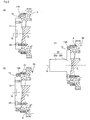
- Figure 2 shows longitudinal sectional views of examples of output-side arrangements in the planetary gear drive of Figure 1.
- Figure 3 is a longitudinal sectional view of a planetary gear drive according to a second embodiment of the invention.
-
- Figure 1 is a longitudinal sectional view of a planetary gear drive according to a first embodiment of the invention, applied to a single reduction gear. The
planetary gear drive 1 includes aninternal gear 2, asun gear 3 disposed concentrically inside theinternal gear 2, a plurality ofplanetary gears 4 in meshing engagement with theinternal gear 2 and thesun gear 3, acarrier 5 that rotatably supports theplanetary gears 4, and ahousing 6 that houses these parts. Thecarrier 5 is rotatably supported on the inner peripheral surface of thehousing 6 via a tapered roller bearing 7 and a tapered roller bearing 8 attached to the inner peripheral surface of thehousing 6. Acoupling 9 located concentrically on the input side of thesun gear 3 connects thesun gear 3 to a rotation input shaft (not shown) such as a motor output shaft. Apinion 10 constituting an output member is affixed by afixing bolt 11 concentrically to the output end of thecarrier 5. - Details of each part will now be explained. The
housing 6 comprises an input-sidecylindrical housing 6a and an output-sidecylindrical housing 6b, between which is theinternal gear 2. Theinternal gear 2 is a thin, elastically resilient internal gear capable of being radially elastically deformed, comprising anannular flange 2a, a thin,cylindrical portion 2b extending from the output side of theflange 2a, andinternal teeth 2c formed on the inner peripheral surface of the thin,cylindrical portion 2b. A plurality ofbolts 12 is used to fix thehousings flange 2a clamped therebetween. Formed on the outside peripheral surface of the output-sidecylindrical housing 6b is an outward-projectingflange 6c. Screw-holes 6d are formed in theflange 6c for affixing thehousing 6 to an affixing member (not shown). - The thin,
cylindrical portion 2b extends around the inner peripheral surface of the output-sidecylindrical housing 6b. Anannular space 6e is formed between the outer peripheral surface of thecylindrical portion 2b and the inner peripheral surface of the output-sidecylindrical housing 6b to permit outward radial elastic deformation of thecylindrical portion 2b. - The
carrier 5 positioned concentrically within thehousing 6 includes an output-side disc-shapedend plate portion 5a, and acylindrical portion 5b that extends from the disc-shapedend plate portion 5a, concentrically withdrive axis 1a, towards the input side. The disc-shapedend plate portion 5a is rotatably supported on the inner peripheral surface of thehousing 6 via the output-side tapered roller bearing 8, and the input side of thecylindrical portion 5b is rotatably supported on the inner peripheral surface of thehousing 6 via the input-side tapered roller bearing 7. - The
sun gear 3 is inserted concentrically into the input side of thecylindrical portion 5b. Thesun gear 3 has anexternal teeth portion 3a, and ashank 3b that extends concentrically from the input end of theexternal teeth portion 3a. Theshank 3b is connected to thecoupling 9 provided concentrically on the input side of theshank 3b. Just one end of thesun gear 3 is supported by thecoupling 9, so that theexternal teeth portion 3a floats perpendicularly to thedrive axis 1a. - The part of the
cylindrical portion 5b facing theexternal teeth portion 3a has a space in which the planetary gears are mounted at fixed angular intervals in the peripheral direction. Theplanetary gears 4 are rotatably supported on aplanetary shaft 4a suspended between the disc-shapedend plate portion 5a and thecylindrical portion 5b, with each of theplanetary gears 4 in meshed engagement with thesun gear 3 and theinternal gear 2. - The output-side configuration of the
planetary gear drive 1 will now be explained.Bolts 14 are used to concentrically affix the output end of thecylindrical housing 6b to anannular flange 13. Theshank 10a of apinion 10 passes through thecenter hole 13a of theflange 13 and into the disc-shapedend plate portion 5a of thecarrier 5, and is fixed in place by abolt 11. Anoil seal 15 is provided between theshank 10a and theflange 13. - As described above, the
sun gear 3 is affixed to thecoupling 9 on the input side of theplanetary gear drive 1. A rotational input shaft, such as a motor output shaft, is affixed to the cylindrical input-side portion of thecoupling 9. Anannular flange 6f extends inwards from the inner peripheral surface of thecylindrical housing 6b. Anoil seal 16 is provided between the inner peripheral surface of theflange 6f and the outer surface of thecoupling 9. - The
internal gear 2 used by theplanetary gear drive 1 has a thin, elastically resilient constitution and thesun gear 3 floats, so that any meshing error caused by assembly error that may arise in the assembly of thegears internal gear 2 and radial movement of thesun gear 3, automatically forming a low-backlash meshing state. Moreover, thecarrier 5 is maintained by both input-side and output-sidetapered roller bearings planetary gear drive 1. - Various output-side arrangements can be employed, as shown in Figure 2. In Figure 2 (a), an
annular flange 13A is affixed to the end of thecylindrical housing 6b, inside which a disc-shaped output-side flange 21 is rotatably positioned via anoil seal 15. The output-side flange 21 is fastened to the output end of thecarrier 5 bybolts 22. - In the arrangement of Figure 2 (b), output-side intrusion of external foreign matter is prevented by the provision of a
seal 23 on the output side of theoil seal 15 shown in Figure 2 (a). In the arrangement of Figure 2 (c), in place of the output-side flange 21, there is anoutput member 24 composed of anoutput shank 24b that extends concentrically from an output-side flange portion 24a. - Figure 3 is a longitudinal sectional view of a double reduction type planetary gear drive according to a second embodiment of the invention. The
planetary gear drive 30 is a two-stage type comprising a first-stageplanetary gear mechanism 40 and a second-stageplanetary gear mechanism 50. The structure of the second-stageplanetary gear mechanism 50 is substantially the same as that of theplanetary gear drive 1 of Figure 1; the output member has the shank arrangement of Figure 2 (c). - The first-stage
planetary gear mechanism 40 is located inside the input side of the carriercylindrical portion 5b, and includes a first-stageinternal gear 41 formed on the inner peripheral surface of thecylindrical portion 5b, an annular first-stage carrier 42 set concentrically onto the outer peripheral surface of the input-side shank 3b of thesun gear 3, a plurality of first-stageplanetary gears 43 rotatably supported by the first-stage carrier 42, and a first-stage sun gear 44 located concentrically on the input side of theshank 3b. The first-stageplanetary gears 43 are in meshed engagement with the first-stage sun gear 44 and the first-stageinternal gear 41. Acoupling 9A is attached to the input-side shank 44a of the first-stage sun gear 44. In this embodiment, thesun gear 3 and the first-stage sun gear 44 can both float perpendicularly to the drive axis. - As in the
planetary gear drive 1 of Figure 1, theinternal gear 2 used in the second stage of theplanetary gear drive 30 is a thin, elastically resilient gear, and the first-stage and second-stage sun gears 3 and 44 are maintained in a floating state that allows them to move radially. Therefore, any uneven meshing caused by error in the assembly or manufacture of thegears internal gear 2 and the movement of the sun gears 3 and 44. This makes it possible to reduce backlash. Moreover, the use of two taperedroller bearings - The
planetary gear drive 30 can of course use the output member arrangements shown in Figure 1 and Figure 2 (a) and (b). - As described in the foregoing, in the planetary gear drive according to this invention, the internal gear has a thin, elastically resilient constitution, and the sun gears are able to move perpendicularly to the drive axis, and the carrier is supported by a pair of tapered roller bearings. As a result, in accordance with this invention, it is possible to achieve a planetary gear drive that has low backlash and a high moment capacity.
Claims (7)
- A planetary gear drive, comprising:an internal gear,a sun gear disposed concentrically within the internal gear,at least one planetary gear in meshed engagement with the internal gear and sun gear,a carrier that rotatably supports the planetary gear,a housing that houses the above gears and carrier, andan input-side tapered roller bearing and an output-side tapered roller bearing attached to an inner peripheral surface of the housing, said tapered roller bearings being positioned along a drive axis at each end of the internal gear, whereinthe carrier has an output-side disc-shaped end plate portion and a cylindrical portion extending to an input side of the drive from the output-side disc-shaped end plate portion, the disc-shaped end plate portion of the carrier is rotatably supported on an inner peripheral surface of the housing by means of the output-side tapered roller bearing, an input-side portion of the cylindrical portion of the carrier is rotatably supported on the inner peripheral surface of the housing by means of the input-side tapered roller bearing, and the sun gear is inserted concentrically into the cylindrical portion from the input side, whereinthe internal gear is a thin, elastically resilient internal gear capable of radial elastic deformation, and whereinthe sun gear is incorporated in a floating state that enables it to move perpendicularly to the axis.
- A planetary gear drive according to claim 1, wherein the internal gear comprises an annular flange affixed to the housing, a thin, cylindrical portion extending from the flange to an output side of the drive, and internal teeth formed on an inner peripheral surface of the thin, cylindrical portion, and wherein
an annular space is formed between an outer peripheral surface of the cylindrical portion and the inner peripheral surface of the housing that allows outward radial elastic deformation of the thin, cylindrical portion. - A planetary gear drive according to claim 2, wherein the housing comprises an input-side cylindrical housing and an output-side cylindrical housing fixed concentrically together with the annular flange of the internal gear clamped therebetween.
- A planetary gear drive according to any of claims 1 to 3, further comprising an annular flange affixed concentrically on an output end of the housing, an output member connected concentrically to an output end of the disc-shaped end-plate portion of the carrier, and an oil seal disposed between the annular flange and the output member.
- A planetary gear drive according to claim 4, wherein the output member is a round output shaft, a pinion or a disc-shaped flange.
- A planetary gear drive according to claim 5, further comprising a seal provided between the flange and the output-side member to prevent intrusion of external foreign matter.
- A planetary gear drive according to any of claims 1 to 6, further comprising a first-stage planetary gear mechanism located inside an input side of the cylindrical portion of the carrier, wherein
the first-stage planetary gear mechanism comprises
a first-stage internal gear formed on an inner peripheral surface of the cylindrical portion,
a first-stage carrier set concentrically onto an outer peripheral surface of the input-side shank of the sun gear,
at least one first-stage planetary gear rotatably supported by the first-stage carrier, and
a first-stage sun gear located concentrically on an input side of the sun gear shank, and wherein
the first-stage sun gear is provided in a floating state that enables the first-stage sun gear to move perpendicularly to the drive axis.
Applications Claiming Priority (2)
| Application Number | Priority Date | Filing Date | Title |
|---|---|---|---|
| JP2003175940 | 2003-06-20 | ||
| JP2003175940A JP4353735B2 (en) | 2003-06-20 | 2003-06-20 | Planetary gear set |
Publications (3)
| Publication Number | Publication Date |
|---|---|
| EP1489337A2 true EP1489337A2 (en) | 2004-12-22 |
| EP1489337A3 EP1489337A3 (en) | 2010-03-24 |
| EP1489337B1 EP1489337B1 (en) | 2017-06-28 |
Family
ID=33411001
Family Applications (1)
| Application Number | Title | Priority Date | Filing Date |
|---|---|---|---|
| EP04012913.2A Expired - Lifetime EP1489337B1 (en) | 2003-06-20 | 2004-06-01 | Planetary gear drive |
Country Status (4)
| Country | Link |
|---|---|
| US (1) | US7059996B2 (en) |
| EP (1) | EP1489337B1 (en) |
| JP (1) | JP4353735B2 (en) |
| KR (1) | KR101015004B1 (en) |
Cited By (5)
| Publication number | Priority date | Publication date | Assignee | Title |
|---|---|---|---|---|
| CN102853036A (en) * | 2012-09-07 | 2013-01-02 | 王榕生 | Planetary gear driven floating load-balancing mechanism of sun gear |
| WO2013004484A1 (en) * | 2011-07-01 | 2013-01-10 | Robert Bosch Gmbh | Adjustment drive for a vehicle, in particular tailgate drive |
| WO2019120035A1 (en) * | 2017-12-22 | 2019-06-27 | 深圳新创技术研究有限公司 | Rolling cycloid planetary transmission mechanism |
| DE102010036063B4 (en) * | 2009-09-03 | 2020-12-17 | Sumitomo Heavy Industries, Ltd. | Planetary reduction gear |
| CN112855902A (en) * | 2021-02-25 | 2021-05-28 | 天地上海采掘装备科技有限公司 | Compact power system for internal power driven large speed ratio pump |
Families Citing this family (16)
| Publication number | Priority date | Publication date | Assignee | Title |
|---|---|---|---|---|
| JP5099746B2 (en) * | 2007-02-26 | 2012-12-19 | 小林クリエイト株式会社 | Rewrite recording medium and manufacturing method thereof |
| DE102007033806B4 (en) * | 2007-07-17 | 2011-03-17 | Nordex Energy Gmbh | Transmission for a wind turbine |
| JP2009133380A (en) * | 2007-11-29 | 2009-06-18 | Ogasawara Precision Engineering:Kk | Thin Mysterious Planetary Gear |
| DE102009042591B4 (en) * | 2008-12-15 | 2012-12-06 | Sew-Eurodrive Gmbh & Co. Kg | planetary gear |
| DE102009007105B4 (en) * | 2009-02-02 | 2011-06-01 | Neugart Gmbh | Planetary gear with a driven part supported by two rolling bearings |
| US8038570B2 (en) * | 2009-03-23 | 2011-10-18 | Bucyrus Mining Equipment, Inc. | Axial thrust control for gearing |
| KR101154846B1 (en) * | 2009-12-22 | 2012-06-18 | 한국항공우주연구원 | turbopump system using a planetary gear device |
| WO2014027383A1 (en) | 2012-08-17 | 2014-02-20 | 株式会社ハーモニック・ドライブ・システムズ | Rigid coupling |
| CN102927207B (en) * | 2012-11-05 | 2015-08-05 | 合肥波林新材料有限公司 | A kind of zero back clearance planetary transmission speed reducer |
| JP2016205603A (en) | 2015-04-28 | 2016-12-08 | 株式会社ハーモニック・ドライブ・システムズ | Planetary gear reduction gear |
| ES2935600T3 (en) * | 2015-09-04 | 2023-03-08 | Desch Antriebstechnik Gmbh & Co Kg | planetary gear |
| US20180062479A1 (en) * | 2016-08-24 | 2018-03-01 | Cts Corporation | Modular Vehicle Engine Component Actuator |
| KR20190008604A (en) | 2017-07-17 | 2019-01-25 | (주)한국미래기술 | Motor having angular contact ball bearing |
| JP6725594B2 (en) | 2018-06-28 | 2020-07-22 | ファナック株式会社 | Spindle device |
| US12297893B2 (en) | 2021-07-30 | 2025-05-13 | Minebea Mitsumi Inc. | Speed reducer |
| JP2023020421A (en) * | 2021-07-30 | 2023-02-09 | ミネベアミツミ株式会社 | Decelerator |
Citations (5)
| Publication number | Priority date | Publication date | Assignee | Title |
|---|---|---|---|---|
| DE20103091U1 (en) | 2001-02-21 | 2001-05-03 | Stöber Antriebstechnik GmbH & Co, 75177 Pforzheim | Planetary gear |
| US6290625B1 (en) | 1998-12-21 | 2001-09-18 | Harmonic Drive Systems, Inc. | Small backlash planetary gear assembly |
| WO2001092759A1 (en) | 2000-05-27 | 2001-12-06 | Alpha Getriebebau Gmbh | Planetary gear with little play |
| DE10123548A1 (en) | 2000-06-06 | 2001-12-20 | Sew Eurodrive Gmbh & Co | Planetary transmission has housing sections of austenite-bainite cast iron and transmission components of case-hardened steel in a compact and low-cost assembly |
| US20020091030A1 (en) | 2000-12-21 | 2002-07-11 | Takashi Haga | Support structure for planet gear in simple planetary gear mechanism and method for manufacturing the mechanism |
Family Cites Families (6)
| Publication number | Priority date | Publication date | Assignee | Title |
|---|---|---|---|---|
| JP3526631B2 (en) * | 1994-08-19 | 2004-05-17 | 株式会社ハーモニック・ドライブ・システムズ | Planetary gear set |
| JPH11505309A (en) * | 1995-05-09 | 1999-05-18 | アルファ ゲトリーベバウ ゲゼルシャフト ミット ベシュレンクテル ハフツング | Two-stage planetary gear set |
| WO1999025992A1 (en) * | 1996-05-21 | 1999-05-27 | Harmonic Drive Systems Inc. | Planetary gear device |
| DE19956789A1 (en) | 1999-11-25 | 2001-05-31 | Zahnradfabrik Friedrichshafen | Planetary gear for mounting on electric motor, has sealing element between sun wheel shaft, and housing arranged axially outside output shaft accommodation region in reduced diameter section |
| DE10144805A1 (en) * | 2001-09-12 | 2003-04-10 | Zahnradfabrik Friedrichshafen | planetary gear |
| DE10144803B4 (en) | 2001-09-12 | 2006-03-09 | Zf Friedrichshafen Ag | planetary gear |
-
2003
- 2003-06-20 JP JP2003175940A patent/JP4353735B2/en not_active Expired - Lifetime
-
2004
- 2004-06-01 EP EP04012913.2A patent/EP1489337B1/en not_active Expired - Lifetime
- 2004-06-18 KR KR1020040045636A patent/KR101015004B1/en not_active Expired - Lifetime
- 2004-06-18 US US10/870,153 patent/US7059996B2/en not_active Expired - Lifetime
Patent Citations (5)
| Publication number | Priority date | Publication date | Assignee | Title |
|---|---|---|---|---|
| US6290625B1 (en) | 1998-12-21 | 2001-09-18 | Harmonic Drive Systems, Inc. | Small backlash planetary gear assembly |
| WO2001092759A1 (en) | 2000-05-27 | 2001-12-06 | Alpha Getriebebau Gmbh | Planetary gear with little play |
| DE10123548A1 (en) | 2000-06-06 | 2001-12-20 | Sew Eurodrive Gmbh & Co | Planetary transmission has housing sections of austenite-bainite cast iron and transmission components of case-hardened steel in a compact and low-cost assembly |
| US20020091030A1 (en) | 2000-12-21 | 2002-07-11 | Takashi Haga | Support structure for planet gear in simple planetary gear mechanism and method for manufacturing the mechanism |
| DE20103091U1 (en) | 2001-02-21 | 2001-05-03 | Stöber Antriebstechnik GmbH & Co, 75177 Pforzheim | Planetary gear |
Non-Patent Citations (1)
| Title |
|---|
| "SUMITOMO CYCLO EUROPE KATALOG/CATALOGUE - F2C-A 75 G", SUMITOMO CYCLO EUROPE CATALOGUE/KATALOG, XX, XX, 1 May 1998 (1998-05-01), XX, XP002988378 |
Cited By (8)
| Publication number | Priority date | Publication date | Assignee | Title |
|---|---|---|---|---|
| DE102010036063B4 (en) * | 2009-09-03 | 2020-12-17 | Sumitomo Heavy Industries, Ltd. | Planetary reduction gear |
| WO2013004484A1 (en) * | 2011-07-01 | 2013-01-10 | Robert Bosch Gmbh | Adjustment drive for a vehicle, in particular tailgate drive |
| CN103620263A (en) * | 2011-07-01 | 2014-03-05 | 罗伯特·博世有限公司 | Adjustment drive for a vehicle, in particular tailgate drive |
| CN103620263B (en) * | 2011-07-01 | 2017-04-19 | 罗伯特·博世有限公司 | Adjustment drive for a vehicle, in particular tailgate drive |
| CN102853036A (en) * | 2012-09-07 | 2013-01-02 | 王榕生 | Planetary gear driven floating load-balancing mechanism of sun gear |
| CN102853036B (en) * | 2012-09-07 | 2015-06-10 | 王榕生 | Planetary gear driven floating load-balancing mechanism of sun gear |
| WO2019120035A1 (en) * | 2017-12-22 | 2019-06-27 | 深圳新创技术研究有限公司 | Rolling cycloid planetary transmission mechanism |
| CN112855902A (en) * | 2021-02-25 | 2021-05-28 | 天地上海采掘装备科技有限公司 | Compact power system for internal power driven large speed ratio pump |
Also Published As
| Publication number | Publication date |
|---|---|
| KR101015004B1 (en) | 2011-02-16 |
| EP1489337B1 (en) | 2017-06-28 |
| JP4353735B2 (en) | 2009-10-28 |
| EP1489337A3 (en) | 2010-03-24 |
| JP2005009614A (en) | 2005-01-13 |
| US7059996B2 (en) | 2006-06-13 |
| US20040259677A1 (en) | 2004-12-23 |
| KR20040111181A (en) | 2004-12-31 |
Similar Documents
| Publication | Publication Date | Title |
|---|---|---|
| US7059996B2 (en) | Planetary gear drive | |
| JP5023606B2 (en) | Electric drive | |
| JP4850129B2 (en) | Final reduction gear | |
| CN101779061B (en) | Output gear-equipped reduction device and method of assembling the same | |
| US20020017160A1 (en) | Gear drive unit | |
| JP2004522921A (en) | Pinion with double-sided fixed tapered roller bearing for differential gears. | |
| WO1999025992A1 (en) | Planetary gear device | |
| US11486468B2 (en) | Gear for a gear train | |
| CN102686913A (en) | Planetary gear pinion shaft support structure | |
| US20170366066A1 (en) | Mounting structure and gear motor comprising same | |
| EP0674123B1 (en) | Supporting structure of a ring gear supporting member in a planetary gear device | |
| EP1485272B1 (en) | Gear mechanism for use in controlling vehicle rear-view mirrors and measuring angular deflection of an articulated trailer relative to the tractor | |
| JP3573294B2 (en) | Small planetary gear reducer | |
| JP4576162B2 (en) | Reducer series | |
| US20240376966A1 (en) | Automobile Sunroof Adjustment Mechanism | |
| JP2896080B2 (en) | Transmissions used in geared motor series | |
| US5649456A (en) | Transmission gear support structure | |
| WO2002099311A2 (en) | Tandem axle pinion shaft subassembly | |
| JPH0849758A (en) | Gearing for terminal reduction gear | |
| JP3444974B2 (en) | Differential device | |
| JP2711154B2 (en) | Bearing mounting structure | |
| JP2007127165A (en) | Supporting structure of planetary rotator | |
| US12181023B1 (en) | Planetary gear reduction mechanism | |
| JP3997616B2 (en) | Shaft support device in differential device | |
| JPH0341239A (en) | Epicycle reduction gear |
Legal Events
| Date | Code | Title | Description |
|---|---|---|---|
| PUAI | Public reference made under article 153(3) epc to a published international application that has entered the european phase |
Free format text: ORIGINAL CODE: 0009012 |
|
| AK | Designated contracting states |
Kind code of ref document: A2 Designated state(s): AT BE BG CH CY CZ DE DK EE ES FI FR GB GR HU IE IT LI LU MC NL PL PT RO SE SI SK TR |
|
| AX | Request for extension of the european patent |
Extension state: AL HR LT LV MK |
|
| TPAC | Observations filed by third parties |
Free format text: ORIGINAL CODE: EPIDOSNTIPA |
|
| TPAB | Information related to observations by third parties deleted |
Free format text: ORIGINAL CODE: EPIDOSDTIPA |
|
| TPAC | Observations filed by third parties |
Free format text: ORIGINAL CODE: EPIDOSNTIPA |
|
| PUAL | Search report despatched |
Free format text: ORIGINAL CODE: 0009013 |
|
| AK | Designated contracting states |
Kind code of ref document: A3 Designated state(s): AT BE BG CH CY CZ DE DK EE ES FI FR GB GR HU IE IT LI LU MC NL PL PT RO SE SI SK TR |
|
| AX | Request for extension of the european patent |
Extension state: AL HR LT LV MK |
|
| RIC1 | Information provided on ipc code assigned before grant |
Ipc: F16H 57/12 20060101ALI20100218BHEP Ipc: F16H 1/28 20060101AFI20040930BHEP |
|
| 17P | Request for examination filed |
Effective date: 20100702 |
|
| AKX | Designation fees paid |
Designated state(s): CZ DE FR IT |
|
| 17Q | First examination report despatched |
Effective date: 20101203 |
|
| STAA | Information on the status of an ep patent application or granted ep patent |
Free format text: STATUS: EXAMINATION IS IN PROGRESS |
|
| GRAP | Despatch of communication of intention to grant a patent |
Free format text: ORIGINAL CODE: EPIDOSNIGR1 |
|
| STAA | Information on the status of an ep patent application or granted ep patent |
Free format text: STATUS: GRANT OF PATENT IS INTENDED |
|
| INTG | Intention to grant announced |
Effective date: 20170127 |
|
| RAP1 | Party data changed (applicant data changed or rights of an application transferred) |
Owner name: HARMONIC DRIVE SYSTEMS INC. |
|
| RIN1 | Information on inventor provided before grant (corrected) |
Inventor name: SHIROKOSHI, NORIO C/O HARMONIC DRIVE SYSTEMS INC., |
|
| GRAS | Grant fee paid |
Free format text: ORIGINAL CODE: EPIDOSNIGR3 |
|
| GRAA | (expected) grant |
Free format text: ORIGINAL CODE: 0009210 |
|
| STAA | Information on the status of an ep patent application or granted ep patent |
Free format text: STATUS: THE PATENT HAS BEEN GRANTED |
|
| AK | Designated contracting states |
Kind code of ref document: B1 Designated state(s): CZ DE FR IT |
|
| REG | Reference to a national code |
Ref country code: DE Ref legal event code: R096 Ref document number: 602004051450 Country of ref document: DE |
|
| REG | Reference to a national code |
Ref country code: DE Ref legal event code: R097 Ref document number: 602004051450 Country of ref document: DE |
|
| REG | Reference to a national code |
Ref country code: FR Ref legal event code: PLFP Year of fee payment: 15 |
|
| PLBE | No opposition filed within time limit |
Free format text: ORIGINAL CODE: 0009261 |
|
| STAA | Information on the status of an ep patent application or granted ep patent |
Free format text: STATUS: NO OPPOSITION FILED WITHIN TIME LIMIT |
|
| 26N | No opposition filed |
Effective date: 20180329 |
|
| PGFP | Annual fee paid to national office [announced via postgrant information from national office to epo] |
Ref country code: IT Payment date: 20230421 Year of fee payment: 20 Ref country code: FR Payment date: 20230420 Year of fee payment: 20 Ref country code: DE Payment date: 20230420 Year of fee payment: 20 Ref country code: CZ Payment date: 20230531 Year of fee payment: 20 |
|
| REG | Reference to a national code |
Ref country code: DE Ref legal event code: R071 Ref document number: 602004051450 Country of ref document: DE |
|
| PG25 | Lapsed in a contracting state [announced via postgrant information from national office to epo] |
Ref country code: CZ Free format text: LAPSE BECAUSE OF EXPIRATION OF PROTECTION Effective date: 20240601 |
|
| PG25 | Lapsed in a contracting state [announced via postgrant information from national office to epo] |
Ref country code: CZ Free format text: LAPSE BECAUSE OF EXPIRATION OF PROTECTION Effective date: 20240601 |