EP1488965A1 - Device for triggering a quickly movable component - Google Patents
Device for triggering a quickly movable component Download PDFInfo
- Publication number
- EP1488965A1 EP1488965A1 EP03013633A EP03013633A EP1488965A1 EP 1488965 A1 EP1488965 A1 EP 1488965A1 EP 03013633 A EP03013633 A EP 03013633A EP 03013633 A EP03013633 A EP 03013633A EP 1488965 A1 EP1488965 A1 EP 1488965A1
- Authority
- EP
- European Patent Office
- Prior art keywords
- lever
- holding position
- locking lever
- locking
- movement
- Prior art date
- Legal status (The legal status is an assumption and is not a legal conclusion. Google has not performed a legal analysis and makes no representation as to the accuracy of the status listed.)
- Granted
Links
Images


Classifications
-
- B—PERFORMING OPERATIONS; TRANSPORTING
- B60—VEHICLES IN GENERAL
- B60R—VEHICLES, VEHICLE FITTINGS, OR VEHICLE PARTS, NOT OTHERWISE PROVIDED FOR
- B60R21/00—Arrangements or fittings on vehicles for protecting or preventing injuries to occupants or pedestrians in case of accidents or other traffic risks
- B60R21/34—Protecting non-occupants of a vehicle, e.g. pedestrians
-
- B—PERFORMING OPERATIONS; TRANSPORTING
- B60—VEHICLES IN GENERAL
- B60R—VEHICLES, VEHICLE FITTINGS, OR VEHICLE PARTS, NOT OTHERWISE PROVIDED FOR
- B60R21/00—Arrangements or fittings on vehicles for protecting or preventing injuries to occupants or pedestrians in case of accidents or other traffic risks
- B60R21/02—Occupant safety arrangements or fittings, e.g. crash pads
- B60R21/13—Roll-over protection
- B60R2021/132—Roll bars for convertible vehicles
- B60R2021/134—Roll bars for convertible vehicles movable from a retracted to a protection position
- B60R2021/135—Roll bars for convertible vehicles movable from a retracted to a protection position automatically during an accident
-
- B—PERFORMING OPERATIONS; TRANSPORTING
- B60—VEHICLES IN GENERAL
- B60R—VEHICLES, VEHICLE FITTINGS, OR VEHICLE PARTS, NOT OTHERWISE PROVIDED FOR
- B60R21/00—Arrangements or fittings on vehicles for protecting or preventing injuries to occupants or pedestrians in case of accidents or other traffic risks
- B60R21/34—Protecting non-occupants of a vehicle, e.g. pedestrians
- B60R21/38—Protecting non-occupants of a vehicle, e.g. pedestrians using means for lifting bonnets
Definitions
- the invention relates to a device for triggering fast moving Components, in particular safety components, according to the preamble of the claim 1.
- DE 198 21 594 A1 shows a device for triggering a roll bar of a convertible vehicle in the event of a rollover. This includes three pivoting levers supported against each other in the holding position. It must be ensured be that an unwanted triggering, such as shocks when driving over potholes, is excluded, but on the other hand the required release force and the required release path for the device so is as small as possible in order to keep the triggering actuator small and light and to be able to set the release speed as high as possible.
- the invention has for its object to a device of the type mentioned improve.
- the invention solves this problem by a device with the features of Claim 1, by a device with the features of claim 14 and of claim 15 and claim 16, individually or in combination can be trained.
- a device with the features of claim 14 and of claim 15 and claim 16 individually or in combination can be trained.
- a torque further lever unloaded arrangement of the operating lever in the holding position ensures that the triggering actuator, such as an electromagnet, is not against one must work on such torque.
- the actuator can therefore be smaller and Easier training and short travel distance ensure a quick release.
- the locking lever is supported or an intermediate lever self-stabilizing, so that an unwanted Triggering is reliably excluded.
- the locking member is in the holding position indirectly via one or more Intermediate lever or supported directly on the actuating lever in such a way that a force oriented in the plane of its axis of rotation acts on it, a torque on the operating lever can be reliably avoided.
- the force is then applied to the center of the axis of rotation, so that none Total torque on this lever results.
- a very vibration and shock resistant training results when the locking member is formed by a pivot lever, which is in the holding position a pivotable intermediate lever blocking the movement of the locking member supported on the operating lever.
- the device is reversible from the release position into the holding position possible by mechanical pressure on the levers, which through this Pressure to be put back into the stop position so that the difference for explosion-triggered tripping, the cost of triggering an inventive Device are small.
- a modular design according to claim 14 ensures that the assembly costs can be kept low.
- the reliability of the device thereby increases that the position of the triggering lever and the spring-loaded Unit must not be adjusted against each other during installation, but the completely set up and adjusted module can be assembled in the Motor vehicle are used.
- the prestressed Module when installing the prestressed Module the risk of a false trigger compared to one only during installation reduced to exciting spring.
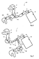
- the device 1 shown in FIG. 1 shows a partial area 2 of a when triggered fast moving unit, such as one that can be moved upwards in the event of a crash Bonnet, a roll bar that can be extended in a translatory or rotary manner, an active headrest, a seat or headrest adjustment, an active Bumper or similar component or assembly. From this one is here only one with a holding part 3, such as a pin, stub axle or the like, provided lever 4 shown.
- the lever 4 is by at least one strong spring 5, here a coil spring, or another drive biased in the sense of release, so that a large force 6 acts on the holding part 3 in the triggering direction.
- the holding part 3 is in the holding position shown in a mouth 7 of a locking member, here as a locking lever 8 which can be pivoted about an axis 9 is trained. Since the Haiteteilability 7 close to the axis of rotation 9 lies (lever arm 10), despite the great attacking force 6 that on the Locking lever 8 acting torque relatively low. The high power 6 the spring 5 is required for rapid movement of the assembly, such as one Roll bar to ensure in the event of a crash.
- the support takes place in such a way that from the intermediate lever 13 into the actuating lever 17 initiated force 18 in the direction of the axis of rotation 19 of the actuating lever 17 points and therefore does not exert a resulting torque on it.
- the force 18 of the intermediate lever 13 results from that exerted by the spring 5 Torque on the locking lever 8 by this as another Torque is transmitted to the intermediate lever 13.
- the direction of it resulting force 18 lies in one plane with the axis of rotation 19 of the actuating lever 17.
- the opposite the force application point with respect to the axis 19 located free end 20 of the operating lever 17 forms a lever arm 21, via which the actuator 16 pivots the actuating lever in the holding position 17 prevents and acts on this to trigger.
- the actuator 16 works against the friction torque that results from the force 18 and the lever arm between the Force application point of the force 18 and the axis of rotation 19 of the actuating lever 17 results against the frictional torque in the axis of rotation 19 and possibly against the restoring force a spring 31 (see e.g. Fig. 10).
- the spring 31 can usually Replace return spring (not shown) located in an actuator 16.
- the locking lever 8, the intermediate lever 13 and the operating lever 17 in the holding position, in which they at least non-positively in Connect, a gearbox that has a large acting in the sense of release Force 6 of the spring 5 on the assembly on the locking lever 8 in a small force geared down on the side of the actuating lever 17 to be held.
- the spring 31 instead of simply supporting the pivoting of the locking lever 8 by a spring 31 effective in the sense of release, the spring 31 alone can do that Trigger, thereby making it possible, as shown in Fig. 12, that the mouth 7 of the locking lever 8 to almost or directly above the axis of rotation 9 runs and the holding part 3 of the assembly without a lever arm 10 above the axis of rotation 9 is held. Then this will not result Torque exerted on the locking lever 8. So that the triggerable Holding force can be very large without increasing the force of the magnetic actuator 16 must what the vibration resistance and security against unwanted triggering further favored.
- the assembly can be reversed by hand by depressing the lever 4 against the spring force 5 possible until the holding part 3 on the receiving mouth of the Locking lever 8 engages.
- the holding part 3 presses on the then obliquely upward facing surface 29 of the receiving mouth 7 of the locking lever 8, so that this tensions the spring optionally assigned to it and due to the lateral offset of the point of attack 29 of the holding part 3 for
- the axis of rotation 9 pivots against the direction 28 into the vertical.
- the operating lever 17 released so that it is counter to the direction 26 again pivoted into its holding position and the intermediate lever 13 locked. Now the lever 4 can be released since it is in its position by the locking lever 8 locked position is held.
- Fig. 5 shows a version of the levers of a device 101, in which the locking lever 108 has two receiving mouths 7, 107 and thus when triggering Swiveling about its axis 109 two units at the same time or in time offset, depending on the geometry of the mouth 7, 107, can release.
- Intermediate lever 13 and operating lever 17 are in the same manner as in the first embodiment educated.
- the device 201 shown there comprises two separate locking levers 8, 208, which are supported on two jaws 12, 212 of an intermediate lever 213 are and when it is pivoted about its axis 214 at the same time or trigger at different times and thus pivot about their respective axes 9, 209, here too the geometry of the mouths 12, 212 the respective point in time determine the triggering.
- the operating lever 17 is in the same way as in first embodiment
- the device 301 according to FIG. 7 includes again two locking levers 8, 308 are provided, but here by two separate intermediate levers 13, 313 are supported. These are around their respective Axes 14, 314 pivotable urid are supported to maintain the stop position an actuating lever 317 in such a way that the forces introduced 18, 318 each point to the center of the axis of rotation 319 of the actuating lever 317, so that here too a resulting torque on the actuating lever 317 is avoided. Alternatively, a mutually canceling introduction of torque would be through the intermediate lever 13, 313 into the operating lever 317 possible.
- a device 401 is shown, which in addition to those in the first embodiment shown levers 8, 13, 17 shows a further locking lever 408, which is pivotable about the axis 409, directly on the end 20 of the actuating lever 17 supports and thus pivot when pivoting can.
- the locking levers 8, 408 can also be here simultaneously or Trigger with a time delay and release several units.
- the overall device 401 is shown schematically in FIG. 13, where there is a structural unit with a Coil spring 5, which is biased in the release direction, is located.
- FIG. 9 shows a combination 501 of the examples shown in FIGS. 5 to 8:
- both the locking lever provided with two receiving areas 7, 107 108 according to the device 101 as well as the second locking lever 208 and that with two receiving jaws 12, 212 according to the device 201 trained intermediate lever 213 available, as well as the other locking lever 308, which is supported on the intermediate lever 313, both locking Intermediate levers 213, 313 come together as in device 301 support the operating lever 317, of which additionally as in the device 401 the further locking lever 408 is immediately secured.
- the locking lever provided with two receiving areas 7, 107 108 according to the device 101 as well as the second locking lever 208 and that with two receiving jaws 12, 212 according to the device 201 trained intermediate lever 213 available, as well as the other locking lever 308, which is supported on the intermediate lever 313, both locking Intermediate levers 213, 313 come together as in device 301 support the operating lever 317, of which additionally as in the device 401 the further locking lever 408 is immediately secured.
- Overall, can with such
- levers need swivel levers be, but also exclusively or additionally translationally relocatable Lever can be used.
- Actuator 16 can also be used instead of the second End 20 of the operating lever 17 at the first end 23 of the operating lever 17 attack, and depending on the selected positioning to the operating lever 17 this by pulling or pushing.
- Fig. 14 the embedding of the device 1 in a module 32 is shown, which as closed box, such as sheet steel, can be formed.
- This module can be in the tensioned state of the spring 5 in the vehicle body are used so that the spring 5 is not tensioned during assembly must and thus the risk of slipping is avoided.
- the assembly security is increased, the assembly costs are reduced. moreover is the exact alignment of the levers 8, 13, 17 on the one hand and possibly that of the lever 4 of the unit, on the other hand, ensures that not only the assembly, but also operational safety also improved.
- the spring 5 can be in the module housing Support 32. When reversing the unit after a trip the spring 5 is simultaneously tensioned and the locking lever 8 is reset, which then resets the pawl 13.
- Such a modular design is also for other devices, for. B. according the described further exemplary embodiments 101, 201, 301, 401, 501, possible.
Abstract
Description
Die Erfindung betrifft eine Vorrichtung zur Auslösung von schnell beweglichen
Bauteilen, insbesondere von Sicherheitsbauteilen, nach dem Oberbegriff des Anspruchs
1.The invention relates to a device for triggering fast moving
Components, in particular safety components, according to the preamble of the
Die DE 198 21 594 A1 zeigt eine Vorrichtung, die zum Auslösen eines Überrollbügels eines Cabriolet-Fahrzeugs bei einem Überschlag dient. Diese umfasst drei sich in Haltestellung gegeneinander abstützende Schwenkhebel. Dabei muss sichergestellt sein, dass eine ungewollte Auslösung, etwa durch Erschütterungen bei Überfahren von Schlaglöchern, ausgeschlossen ist, andererseits jedoch die erforderliche Auslösekraft und der erforderliche Auslöseweg für die Vorrichtung so gering wie möglich ist, um den auslösenden Aktor klein und leicht halten zu können und die Auslösegeschwindigkeit so groß wie möglich einstellen zu können.DE 198 21 594 A1 shows a device for triggering a roll bar of a convertible vehicle in the event of a rollover. This includes three pivoting levers supported against each other in the holding position. It must be ensured be that an unwanted triggering, such as shocks when driving over potholes, is excluded, but on the other hand the required release force and the required release path for the device so is as small as possible in order to keep the triggering actuator small and light and to be able to set the release speed as high as possible.
Der Erfindung liegt die Aufgabe zugrunde, eine Vorrichtung der genannten Art zu verbessern.The invention has for its object to a device of the type mentioned improve.
Die Erfindung löst diese Aufgabe durch eine Vorrichtung mit den Merkmalen des
Anspruchs 1, durch eine Vorrichtung mit den Merkmalen des Anspruchs 14 und
des Anspruchs 15 sowie des Anspruchs 16, die einzeln oder in Kombination miteinander
ausgebildet sein können. Hinsichtlich vorteilhafter Ausgestaltungen wird
auf die abhängigen Ansprüche 2 bis 13 sowie 17 und 18 verwiesen. The invention solves this problem by a device with the features of
Erfindungsgemäß ist nach Anspruch 1 mit der von einem Drehmoment durch
weitere Hebel unbelasteten Anordnung des Betätigungshebels in Haltestellung
sichergestellt, dass der auslösende Aktor, etwa ein Elektromagnet, nicht gegen ein
solches Drehmoment anarbeiten muss. Der Aktor kann daher bei kleiner und
leichter Ausbildung und kurzem Hubweg eine schnelle Auslösung gewährleisten.
Zudem ist in Ermangelung eines Drehmoments die Abstützung des Verriegelungshebels
oder eines Zwischenhebels selbststabilisierend, so dass eine ungewollte
Auslösung zuverlässig ausgeschlossen ist.According to the invention is according to
Wenn sich das Verriegelungsglied in Haltestellung mittelbar über einen oder mehrere Zwischenhebel oder unmittelbar an dem Betätigungshebel derart abstützt, dass auf diesen eine in der Ebene seiner Drehachse orientierte Kraft einwirkt, kann ein Drehmoment auf den Betätigungshebel zuverlässig vermieden werden. Die Krafteinleitung verläuft dann auf das Zentrum der Drehachse zu, so dass kein Gesamtdrehmoment auf diesen Hebel resultiert.If the locking member is in the holding position indirectly via one or more Intermediate lever or supported directly on the actuating lever in such a way that a force oriented in the plane of its axis of rotation acts on it, a torque on the operating lever can be reliably avoided. The force is then applied to the center of the axis of rotation, so that none Total torque on this lever results.
Bei Ausbildung einer Kette nach Art eines Getriebes durch das Verriegelungsglied und den oder die weiteren Hebel in Haltestellung, wobei eine große im Auslösesinn wirkende Kraft des Bauteils am Verriegelungsglied in eine kleine Kraft an der zu haltenden Seite des Betätigungshebels übersetzt wird, kann die erforderliche Auslösekraft durch den Aktor sehr gering gehalten werden.When forming a chain in the manner of a transmission by the locking member and the one or more levers in the holding position, with a large one in the sense of release acting force of the component on the locking member into a small force on the to be held side of the operating lever is translated, the required Tripping force can be kept very low by the actuator.
Eine sehr vibrations- und schockfeste Ausbildung ergibt sich, wenn das Verriegelungsglied von einem Schwenkhebel gebildet ist, der sich in Haltestellung über einen schwenkbaren und die Bewegung des Verriegelungsglieds sperrenden Zwischenhebel an dem Betätigungshebel abstützt.A very vibration and shock resistant training results when the locking member is formed by a pivot lever, which is in the holding position a pivotable intermediate lever blocking the movement of the locking member supported on the operating lever.
Eine Reversibilität der Vorrichtung von der Auslösestellung in die Haltestellung ist etwa durch mechanischen Druck auf die Hebel möglich, welche durch diesen Druck wieder in die Haltestellung zurückgesetzt werden, so dass im Unterschied zu explosionsgetriebenen Auslösungen die Kosten für die Auslösung einer erfindungsgemäßen Vorrichtung gering sind.The device is reversible from the release position into the holding position possible by mechanical pressure on the levers, which through this Pressure to be put back into the stop position so that the difference for explosion-triggered tripping, the cost of triggering an inventive Device are small.
Dabei ist insbesondere in Verbindung mit der Reversibilität eine Ausweitung von schnell auslösenden Systemen auf mehrere Stellen im Kraftfahrzeug sinnvoll, etwa um durch eine sich bereichsweise anhebende Motorhaube eine Knautschzone für anprallende Fußgänger oder Zweiradfahrer schaffen zu können.In connection with reversibility, there is an expansion of quick-triggering systems make sense to several places in the motor vehicle, for example around a crumple zone due to a hood that lifts in certain areas for colliding pedestrians or two-wheelers.
Eine modulare Ausbildung gemäß Anspruch 14 stellt sicher, daß die Montagekosten
gering gehalten werden können. Zudem ist die Zuverlässigkeit der Vorrichtung
dadurch erhöht, daß die Lage der auslösenden Hebel und der federbelasteten
Baueinheit nicht beim Einbau gegeneinander justiert werden müssen, sondern
das fertig eingerichtete und justierte Modul kann insgesamt bei der Montage in das
Kraftfahrzeug eingesetzt werden. Zudem ist bei der Einsetzung des vorgespannten
Moduls die Gefahr einer Fehlauslösung gegenüber einer erst noch beim Einbau
zu spannenden Feder vermindert.A modular design according to
Weitere Vorteile und Merkmale der Erfindung ergeben sich aus in der Zeichnung dargestellten und nachfolgend beschriebenen Ausführungsbeispielen des Gegenstandes der Erfindung.Further advantages and features of the invention emerge from the drawing illustrated and described below embodiments of the subject the invention.
In der Zeichnung zeigt:
- Fig. 1
- eine Gesamtansicht einer erfindungsgemäßen Vorrichtung,
- Fig. 2
- eine schematische Ansicht der in der Vorrichtung wirksamen Hebel in Haltestellung gemäß einem ersten Ausführungsbeispiel,
- Fig. 3
- eine Detaildarstellung eines Verriegelungsglieds mit eingezeichneter Kraft durch die Federbeaufschlagung der Baueinheit und resultierendem Drehmoment im Auslösesinn,
- Fig. 4
- eine ähnliche Darstellung wie Fig. 3 mit einem zusätzlich eingezeichneten Zwischenhebel und dessen Nase zum Angreifen des Verriegelungsglieds beim Reversieren,
- Fig. 5
- eine ähnliche Ansicht wie Fig. 2 eines zweiten Ausführungsbeispiels mit einem Verriegelungsglied, das die gleichzeitige Entriegelung zweier Halterungen ermöglicht,
- Fig. 6
- eine ähnliche Ansicht wie Fig. 5 eines weiteren Ausführungsbeispiels mit zwei Verriegelungsgliedern, die an nur einem Zwischenhebel abgestützt sind,
- Fig. 7
- eine ähnlich Ansicht wie Fig. 6 eines weiteren Ausführungsbeispiels mit zwei Verriegelungsgliedern, die jeweils an einem Zwischenhebel abgestützt sind,
- Fig. 8
- eine ähnlich Ansicht wie Fig. 7 eines weiteren Ausführungsbeispiels mit zwei Verriegelungsgliedern,
- Fig. 9
- eine ähnlich Ansicht wie Fig. 8 eines weiteren Ausführungsbeispiels, das eine Kombination von mehreren der vorher dargestellten Lösungen bildet,
- Fig. 10
- eine Detaildarstellung eines von Federkraft im Haltesinn beaufschlagten Betätigungshebels,
- Fig. 11
- eine Darstellung des Gesamthebelsystems mit der Feder nach Fig. 10, die sich am Verriegelungshebel abstützt und diesen im Auslösesinn beaufschlagt,
- Fig. 12
- eine ähnliche Ansicht wie Fig. 11 mit einem Verriegelungshebel, der durch den Halteteil der Baueinheit kein im Auslösesinn wirksames Drehmoment erfährt,
- Fig. 13
- eine schematische Gesamtansicht einer Vorrichtung mit zwei Verriegelungsgliedern,
- Fig. 14
- eine schematische Gesamtansicht der Vorrichtung gemäß dem ersten Ausführungsbeispiel bei Einbettung in ein komplett montierbares Modul.
- Fig. 1
- an overall view of a device according to the invention,
- Fig. 2
- 2 shows a schematic view of the levers effective in the device in the holding position according to a first exemplary embodiment,
- Fig. 3
- 2 shows a detailed representation of a locking member with the force shown by the spring loading of the structural unit and the resulting torque in the sense of release,
- Fig. 4
- 3 shows a representation similar to FIG. 3 with an additional intermediate lever and its nose for engaging the locking member when reversing,
- Fig. 5
- 2 shows a view similar to FIG. 2 of a second exemplary embodiment with a locking member which enables two brackets to be unlocked at the same time,
- Fig. 6
- 5 shows a view similar to FIG. 5 of a further exemplary embodiment with two locking members which are supported on only one intermediate lever,
- Fig. 7
- 6 shows a view similar to FIG. 6 of a further exemplary embodiment with two locking members, each of which is supported on an intermediate lever,
- Fig. 8
- 7 shows a view similar to FIG. 7 of a further exemplary embodiment with two locking members,
- Fig. 9
- 8 shows a view similar to FIG. 8 of a further exemplary embodiment, which forms a combination of several of the solutions presented above,
- Fig. 10
- a detailed representation of an actuating lever acted upon by spring force in the holding direction,
- Fig. 11
- 10 shows the overall lever system with the spring according to FIG. 10, which is supported on the locking lever and acts on it in the release direction,
- Fig. 12
- 11 is a view similar to FIG. 11 with a locking lever which does not experience any torque effective in the sense of release due to the holding part of the structural unit,
- Fig. 13
- 1 shows a schematic overall view of a device with two locking members,
- Fig. 14
- a schematic overall view of the device according to the first embodiment when embedded in a completely mountable module.
Die in Fig. 1 dargestellte Vorrichtung 1 zeigt einen Teilbereich 2 einer bei Auslösung
schnell beweglichen Baueinheit, etwa einer im Crashfall aufwärts verlagerbaren
Motorhaube, eines translatorisch oder rotatorisch ausfahrbaren Überrollbügels,
einer aktiven Kopfstütze, einer Sitz- oder Kopfstützenverstellung, einer aktiven
Stoßstange oder eines ähnlichen Bauteils oder Baueinheit. Von dieser ist hier
nur ein mit einem Halteteil 3, etwa einem Zapfen, Achsstummel oder dergleichen,
versehener Hebel 4 dargestellt. Der Hebel 4 ist durch zumindest eine starke Feder
5, hier eine Spiralfeder, oder einen anderen Antrieb im Auslösesinn vorgespannt,
so dass auf den Halteteil 3 eine große Kraft 6 in auslösende Richtung wirkt.The
Der Halteteil 3 ist in der gezeigten Haltestellung in einem Maul 7 eines Verriegelungsglieds,
das hier als um eine Achse 9 schwenkbarer Verriegelungshebel 8
ausgebildet ist, aufgenommen. Da die Haiteteilaufnahme 7 nahe an der Drehachse
9 liegt (Hebelarm 10), ist trotz der großen angreifenden Kraft 6 das auf den
Verriegelungshebel 8 einwirkende Drehmoment relativ gering. Die hohe Kraft 6
der Feder 5 ist erforderlich, um eine schnelle Bewegung der Baueinheit, etwa eines
Überrollbügels, im Crashfall zu gewährleisten.The holding
Im hier gezeigten Ausführungsbeispiel ist an seinem lang erstreckten freien, dem
Aufnahmemaul 7 bezüglich der Drehachse 9 gegenüberliegenden Ende 11 der
Verriegelungshebel 8 in einem Aufnahmemaul 12 eines als Sperrklinke dienenden
Zwischenhebels 13 aufgenommen, um in Haltestellung ein Drehen des Verriegelungshebels
8 um die Achse 9 zu verhindern. Der Zwischenhebel 13 muss nicht
zwangsläufig vorhanden sein und ist hier seinerseits als weiterer Schwenkhebel
ausgebildet, der um die Achse 14 schwenkbar ist.In the embodiment shown here is on its long
Um in Haltestellung seine Lage zu sichern, stützt er sich mit seinem dem Aufnahmemaul
12 gegenüberliegenden, lang erstreckten freien Ende 15 an einem von
einem Aktor 16 beeinflußbaren Betätigungshebel 17 ab.In order to secure its position in the holding position, it supports itself with its
Die Abstützung erfolgt derart, dass die von dem Zwischenhebel 13 in den Betätigungshebel
17 eingeleitete Kraft 18 in Richtung der Drehachse 19 des Betätigungshebels
17 weist und daher kein resultierendes Drehmoment auf diesen ausübt.
Die Kraft 18 des Zwischenhebels 13 resultiert aus dem von der Feder 5 ausgeübten
Drehmoment auf den Verriegelungshebel 8, das von diesem als weiteres
Drehmoment auf den Zwischenhebel 13 übertragen wird. Die Richtung der daraus
resultierenden Kraft 18 liegt dabei in einer Ebene mit der Drehachse 19 des Betätigungshebels
17. Das dem Kraftangriffspunkt bezüglich der Achse 19 gegenüber
gelegene freie Ende 20 des Betätigungshebels 17 bildet einen Hebelarm 21 aus,
über den der Aktor 16 in Haltestellung das Verschwenken des Betätigungshebels
17 verhindert und zur Auslösung auf diesen einwirkt. Der Aktor 16 arbeitet gegen
das Reibmoment, das sich aus der Kraft 18 und dem Hebelarm zwischen dem
Kraftangriffspunkt der Kraft 18 und der Drehachse 19 des Betätigungshebels 17
ergibt, gegen das Reibmoment in der Drehachse 19 und ggf. gegen die Rückstellkraft
einer Feder 31 (siehe z.B. Fig. 10). Die Feder 31 kann dabei die üblicherweise
in einem Aktor 16 angeordnete (nicht gezeigt) Rückstellfeder ersetzen.The support takes place in such a way that from the
Insgesamt bilden der Verriegelungshebel 8, der Zwischenhebel 13 und der Betätigungshebel
17 in Haltestellung, in der sie zumindest kraftschlüssig miteinander in
Verbindung stehen, ein Getriebe aus, das eine große im Auslösesinn wirkende
Kraft 6 der Feder 5 auf die Baueinheit am Verriegelungshebel 8 in eine kleine Kraft
an der zu haltenden Seite des Betätigungshebels 17 untersetzt. Dieses resultiert
aus den unterschiedlichen Hebelarmlängen des Verriegelungshebels 8 bezüglich
seiner Drehachse 9, der entsprechenden Gestaltung des Zwischenhebels 13 und
dem Hebelarm 21 des Betätigungshebels 17 an seiner dem oder den Aktor(en) 16
zugewandten Seite 20.Overall, the locking
Im Falle einer Auslösung, beispielsweise bei einem Crash oder bei einem sich anbahnenden
Crash, wird oder werden der oder die Aktor(en) 16 von entsprechenden
Sensoren angesteuert, so dass sich jeweils beispielsweise der Stößel 24 des
Magnetankers in Richtung des Pfeils 25 bewegt, um somit ein Drehmoment auf
das Ende 20 des Betätigungshebels 17 auszuüben. Dieses Drehmoment kann
gegen die Feder 31 (Fig. 10,11) einwirken, die den Betätigungshebel 17 entgegen
der Auslöserichtung des Pfeils 25 vorspannt und somit die Haltestellung gegen ein
ungewolltes Auslösen stabilisiert.In the event of a trigger, for example in the event of a crash or an impending end
Crash, will or will the actuator (s) 16 of corresponding
Controlled sensors so that, for example, the
Durch das bei Auslösung ausgeübte Drehmoment auf den Betätigungshebel 17
schwenkt dieser in Richtung des Pfeils 26 um seine Achse 19 und gibt den als
Sperrklinke wirkenden Zwischenhebel 13 frei. Dieser kann, getrieben von dem
durch die Baueinheit im Auslösesinn vorgespannten Verriegelungshebel 8 und
ggf. einer weiteren, nicht eingezeichneten Feder, in Richtung des Pfeils 27 verschwenken,
so dass das freie Ende 11 des Verriegelungshebels 8 aus dem Maul
12 des Zwischenhebels 13 herausgleiten und in Richtung des Pfeils 28 aufschwenken
kann. Der Verriegelungshebel 8 kann dabei ebenfalls durch eine weitere
Feder - in den Figuren 11 und 12 eingezeichnet und dort mit dem Bezugszeichen
31 versehen - im Auslösesinn vorgespannt sein. Der Halteteil 3 gleitet beim
Verschwenken des Verriegelungshebels 8 aus dessen Aufnahmemaul 7 und kann
explosionsähnlich ausfahren.Due to the torque exerted on the
Anstelle der reinen Unterstützung des Aufschwenkens des Verriegelungshebels 8
durch eine im Auslösesinn wirksame Feder 31 kann auch die Feder 31 allein das
Auslösen bewirken, wodurch es möglich wird, wie in Fig. 12 dargestellt ist, dass
das Maul 7 des Verriegelungshebels 8 bis nahezu oder direkt oberhalb der Drehachse
9 verläuft und der Halteteil 3 der Baueinheit ohne einen Hebelarm 10 oberhalb
der Drehachse 9 gehalten wird. Dann wird durch diese kein resultierendes
Drehmoment auf den Verriegelungshebel 8 ausgeübt. Damit kann die auslösbare
Haltekraft sehr groß sein, ohne dass die Kraft des magnetischen Aktors 16 ansteigen
muss, was die Vibrationsfestigkeit und Sicherheit gegen ungewollte Auslösung
weiter begünstigt.Instead of simply supporting the pivoting of the locking
Durch die Auslösung wird zunächst der Betätigungshebel 17, danach der Zwischenhebel
13 und zuletzt der Verriegelungshebel 8 mechanisch freigegeben -
eventuell durch die Feder 31 zusätzlich beaufschlagt - und die Baueinheit in kürzester
Zeit von typisch weniger als 5 ms über die mit beispielsweise 500 N vorgespannte
Feder 5 ausgefahren.By triggering the operating
Ein Reversieren der Baueinheit ist von Hand durch Niederdrücken des Hebels 4
gegen die Federkraft 5 möglich, bis der Halteteil 3 an dem Aufnahmemaul des
Verriegelungshebels 8 einrastet. Beim Herunterbewegen drückt der Halteteil 3 auf
die dann schräg nach oben weisende Fläche 29 des Aufnahmemauls 7 des Verriegelungshebels
8, so dass dieses die ihm optional zugeordnete Feder spannt
und aufgrund des seitlichen Versatzes des Angriffspunktes 29 des Halteteils 3 zur
Drehachse 9 entgegen der Richtung 28 in die Senkrechte schwenkt. Dabei drückt
der Verriegelungshebel 8 gegen eine Nase 30 des Zwischenhebels 13, so dass
auch dieser wieder in seine Haltestellung geschwenkt wird. Ist diese erreicht, wird
der Betätigungshebel 17 freigegeben, so dass er entgegen der Richtung 26 wieder
in seine Haltestellung verschwenkt und den Zwischenhebel 13 verriegelt. Nun
kann der Hebel 4 losgelassen werden, da er von dem Verriegelungshebel 8 in seiner
verriegelten Position gehalten wird.The assembly can be reversed by hand by depressing the
In weiteren Ausführungsbeispielen sind bei prinzipieller Ähnlichkeit einige Variationen dargestellt:In other exemplary embodiments, there are some variations in principle similarity shown:
Fig. 5 zeigt eine Version der Hebel einer Vorrichtung 101, bei welcher der Verriegelungshebel
108 zwei Aufnahmemäuler 7, 107 aufweist und somit bei auslösendem
Verschwenken um seine Achse 109 zwei Baueinheiten zeitgleich oder zeitlich
versetzt, je nach Geometrie der Mäuler 7, 107, freigeben kann. Zwischenhebel 13
und Betätigungshebel 17 sind in gleicher Weise wie im ersten Ausführungsbeispiel
ausgebildet.Fig. 5 shows a version of the levers of a
Gemäß Fig. 6 umfasst die dort gezeigte Vorrichtung 201 zwei separate Verriegelungshebel
8, 208, die an zwei Mäulern 12, 212 eines Zwischenhebels 213 abgestützt
sind und bei dessen Verschwenken um seine Achse 214 zeitgleich oder
zeitlich versetzt auslösen und somit um ihre jeweiligen Achsen 9, 209 verschwenken,
wobei auch hier die Geometrie der Mäuler 12, 212 den jeweiligen Zeitpunkt
der Auslösung bestimmen. Der Betätigungshebel 17 ist in gleicher Weise wie im
ersten Ausführungsbeispiel ausgebildet6, the
Bei der Vorrichtung 301 nach Fig. 7 sind wie im Ausführungsbeispiel nach Fig. 6
wiederum zwei Verriegelungshebel 8, 308 vorgesehen, die jedoch hier von zwei
getrennten Zwischenhebeln 13, 313 abgestützt sind. Diese sind um ihre jeweiligen
Achsen 14, 314 schwenkbar urid stützen sich zur Wahrung der Haltestellung an
einem Betätigungshebel 317 derart ab, dass sich die eingeleiteten Kräfte 18, 318
jeweils auf das Zentrum der Drehachse 319 des Betätigungshebels 317 weisen,
so dass auch hier ein resultierendes Drehmoment auf den Betätigungshebel 317
vermieden ist. Alternativ wäre auch eine sich gegenseitig aufhebende Drehmomenteinleitung
durch die Zwischenhebel 13, 313 in den Betätigungshebel 317
möglich.As in the exemplary embodiment according to FIG. 6, the device 301 according to FIG. 7 includes
again two locking
In Fig. 8 ist eine Vorrichtung 401 gezeigt, die neben den im ersten Ausführungsbeispiel
gezeigten Hebeln 8, 13, 17 einen weiteren Verriegelungshebel 408 zeigt,
der um die Achse 409 schwenkbar ist, sich unmittelbar auf dem Ende 20 des Betätigungshebels
17 abstützt und bei dessen Verschwenken somit mit verschwenken
kann. Die Verriegelungshebel 8, 408 können damit auch hier zeitgleich oder
zeitversetzt auslösen und mehrere Baueinheiten freigeben. Die Gesamtvorrichtung
401 ist in Fig. 13 schematisch dargestellt, wobei dort eine Baueinheit mit einer
Schraubenfeder 5, die in Auslöserichtung vorgespannt ist, eingezeichnet ist.In Fig. 8 a device 401 is shown, which in addition to those in the first embodiment
shown
Fig. 9 zeigt eine Kombination 501 der in den Figuren 5 bis 8 gezeigten Beispiele:
Hier sind sowohl der mit zwei Aufnahmebereichen 7, 107 versehene Verriegelungshebel
108 gemäß der Vorrichtung 101 als auch der zweite Verriegelungshebel
208 und der mit zwei Aufnahmemäulern 12, 212 gemäß der Vorrichtung 201
ausgebildete Zwischenhebel 213 vorhanden, ebenso wie der weitere Verriegelungshebel
308, der sich an dem Zwischenhebel 313 abstützt, wobei beide sperrenden
Zwischenhebel 213, 313 sich gemeinsam wie in der Vorrichtung 301 an
dem Betätigungshebel 317 abstützen, von dem zusätzlich wie bei der Vorrichtung
401 der weitere Verriegelungshebel 408 unmittelbar gesichert ist. Insgesamt können
mit einer solchen Vorrichtung 501 fünf Baueinheiten gleichzeitig gehalten und
im Bedarfsfall ausgelöst werden.FIG. 9 shows a combination 501 of the examples shown in FIGS. 5 to 8:
Here are both the locking lever provided with two receiving
Weitere Kombinationen sind möglich. Auch müssen nicht alle Hebel Schwenkhebel
sein, sondern auch ausschließlich oder zusätzlich translatorisch verlagerbare
Hebel können Verwendung finden. Auch kann der Aktor 16 anstelle am zweiten
Ende 20 des Betätigungshebels 17 am ersten Ende 23 des Betätigungshebels 17
angreifen, und je nach gewählter Positionierung zum Betätigungshebel 17 diesen
durch eine Zug- oder Schubbewegung auslösen.Other combinations are possible. Also, not all levers need swivel levers
be, but also exclusively or additionally translationally relocatable
Lever can be used.
In Fig. 14 ist die Einbettung der Vorrichtung 1 in ein Modul 32 dargestellt, das als
geschlossener Kasten, etwa aus Stahlblech, ausgebildet sein kann.In Fig. 14 the embedding of the
Damit kann die auszulösende Baueinheit, z. B. ein Aufstellmechanismus für eine
Haube, ohne Federvorspannung montiert werden. Erst durch anschließende
Montage des die Vorrichtung 1 enthaltenden Moduls 32 wird der federgespannte
Hebel 4 mit der Baueinheit verbunden. Es besteht aber auch die Möglichkeit, den
Hebel 4 mit dem Halteteil 3 der auszulösenden Baueinheit zuzuordnen und das
Halteteil 3 bei der Montage des ggf. vorgespannten Moduls in dieses einzufahren.
Damit kann z. B. die aufzustellende Baueinheit für eine Motorhaube mit der Karosserie
lackiert werden; die Vorrichtung 1 in dem Modul 32 wird dann nach der
Lackierung montiert.So that the unit to be triggered, for. B. an installation mechanism for a
Can be mounted without spring preload. Only through subsequent
Assembly of the module 32 containing the
Dieses Modul kann im gespannten Zustand der Feder 5 in die Fahrzeugkarosserie
eingesetzt werden, so daß bei der Montage nicht erst die Feder 5 gespannt werden
muß und somit die dabei gegebene Gefahr eines Abrutschens vermieden ist.
Die Montagesicherheit ist dadurch erhöht, die Montagekosten sind gesenkt. Zudem
ist die exakte Ausrichtung der Hebel 8, 13, 17 einerseits und ggf. die des Hebels
4 der Baueinheit andererseits gewährleistet, was nicht nur die Montage, sondem
auch die Betriebssicherheit verbessert. Die Feder 5 kann sich dabei im Modulgehäuse
32 abstützen. Beim Reversieren der Baueinheit nach einer Auslösung
wird gleichzeitig die Feder 5 gespannt sowie der Verriegelungshebel 8 zurückgestellt,
der dann die Sperrklinke 13 zurücksetzt.This module can be in the tensioned state of the
Eine derartige modulare Ausbildung ist auch für weitere Vorrichtungen, z. B. gemäß
den beschriebenen weiteren Ausführungsbeispielen 101, 201, 301, 401, 501,
möglich. Such a modular design is also for other devices, for. B. according
the described further
- 1,101,201,301,401,5011,101,201,301,401,501
- Vorrichtung,Contraption,
- 22
- Teilbereich der auszulösenden Baueinheit,Part of the unit to be triggered,
- 33
- Halteteil,Holding part,
- 44
- Hebel,Lever,
- 55
- Feder,Feather,
- 66
- Kraftrichtung,Force direction,
- 7,1077,107
- Maul des Verriegelungshebels,Mouth of the locking lever,
- 8,108,208,308,4088,108,208,308,408
- Verriegelungshebel,Locking lever,
- 9,109,209,309,4099,109,209,309,409
- Achse des Verriegelungshebels,Axis of the locking lever,
- 1010
- Hebelarm,lever arm
- 1111
- freies Ende des Verriegelungshebels,free end of the locking lever,
- 12,212,31212,212,312
- Maul des Zwischenhebels,Mouth of the intermediate lever,
- 13,213,31313,213,313
- Zwischenhebel,Intermediate lever,
- 14,214,31414,214,314
- Achse des Zwischenhebels,Axis of the intermediate lever,
- 1515
- freies Ende des Zwischenhebels,free end of the intermediate lever,
- 1616
- Aktor,actuator,
- 17,31717.317
- Betätigungshebel,Actuating lever,
- 18,31818.318
- Kraft,Force,
- 19,31919.319
- Achse des Betätigungshebels,Axis of the operating lever,
- 2020
- zweites Ende des Betätigungshebels,second end of the operating lever,
- 2121
- Hebelarm,lever arm
- 2222
- Kraft,Force,
- 2323
- erstes Ende des Betätigungshebels,first end of the operating lever,
- 2424
- Stößel,ram,
- 2525
- Auslöserichtung des Stößels,Direction of release of the ram,
- 2626
- Schwenkrichtung des Betätigungshebels bei Auslösung,Swing direction of the operating lever when triggered,
- 2727
- Schwenkrichtung des Zwischenhebels bei Auslösung,Swivel direction of the intermediate lever when triggered,
- 2828
- Schwenkrichtung des Verriegelungshebels bei Auslösung,Swivel direction of the locking lever when triggered,
- 2929
- Fläche des Verriegelungshebels,Surface of the locking lever,
- 3030
- Nase des Zwischenhebels,Nose of the intermediate lever,
- 3131
- Feder,Feather,
- 3232
- Modul.Module.
Claims (18)
dadurch gekennzeichnet, dass der Betätigungshebel (17;317) ein Schwenkhebel ist, der in Haltestellung frei von einer resultierenden Drehmomentbeaufschlagung durch den oder die Verriegelungshebel (8;108;208;308;408) oder weitere zwischen dem Verriegelungshebel (8;108;208;308;408) und dem Betätigungshebel (17;317) liegende Hebel (13;213;313) gehalten ist.Device (1; 101; 201; 301; 401; 501) for triggering fast-moving structural units, in particular safety components, the device (1; 101; 201; 301; 401; 501) having at least one locking lever (8; 108; 208; 308; 408;), which blocks the movement of the assembly in the holding position, and wherein the device (1; 101; 201; 301; 401; 501) comprises at least one actuating lever (17; 317) which is in the holding position a movement of the locking lever (8; 108; 208; 308; 408) is directly or indirectly blocked and can be moved to release the holding position by applying force,
characterized in that the actuating lever (17; 317) is a pivoting lever which, in the holding position, is free from a resultant application of torque by the locking lever (s) (8; 108; 208; 308; 408) or further between the locking lever (8; 108; 208 ; 308; 408) and the actuating lever (17; 317) lying lever (13; 213; 313) is held.
dadurch gekennzeichnet, dass der Verriegelungshebel (8;108;208;308;408) in Haltestellung von der auszulösenden Baueinheit im Bewegungssinn der schnell bewegten Auslösung kraftbeaufschlagt (5) ist und sich zur Blockierung dieser Bewegung mittelbar oder unmittelbar an dem Betätigungshebel (17;317) derart abstützt, dass auf diesen eine in der Ebene seiner Drehachse (19;319) orientierte Kraft (18;318) einwirkt.Device according to claim 1,
characterized in that the locking lever (8; 108; 208; 308; 408) in the holding position is subjected to force (5) by the structural unit to be triggered in the direction of movement of the rapidly moving trigger and to block this movement directly or indirectly on the actuating lever (17; 317 ) is supported in such a way that a force (18; 318) oriented in the plane of its axis of rotation (19; 319) acts on it.
dadurch gekennzeichnet, dass der Verriegelungshebel (8;108;208;308;408) und der oder die weiteren Hebel (13;213;313;17;317) in Haltestellung ein Getriebe bilden, das eine große im Auslösesinn wirkende Kraft (6) der Baueinheit am Verriegelungsglied (8;108;208;308;408) in eine kleine Kraft an der zu haltenden Seite des Betätigungshebels (17;317) untersetzt.Device according to one of claims 1 or 2,
characterized in that the locking lever (8; 108; 208; 308; 408) and the further lever (s) (13; 213; 313; 17; 317) form a gear in the holding position, which has a large force (6) acting in the sense of release the assembly on the locking member (8; 108; 208; 308; 408) in a small force on the side of the actuating lever (17; 317) to be held.
dadurch gekennzeichnet, dass der Verriegelungshebel (8;108;208;308;408) von einem Schwenkhebel gebildet ist, der sich in Haltestellung über einen schwenkbaren Zwischenhebel (13;213) an dem Betätigungshebel (17;317) abstützt.Device according to one of claims 1 to 3,
characterized in that the locking lever (8; 108; 208; 308; 408) is formed by a swivel lever which is supported on the actuating lever (17; 317) via a pivotable intermediate lever (13; 213) in the holding position.
dadurch gekennzeichnet, dass der Verriegelungshebel (8;108;208;308;408) zumindest ein nahe (Hebelarm 10) seiner Schwenkachse (9;109;209;309;409) gelegenes Aufnahmemaul (7;107) für einen Achsstummel, Zapfen oder sonstiges Halteteil (3) der auszulösenden Baueinheit und entfernter zu seiner Schwenkachse (9;109;209;309;409) ein lang erstrecktes freies Ende (11) aufweist.Device according to claim 4,
characterized in that the locking lever (8; 108; 208; 308; 408) at least one (lever arm 10) its pivot axis (9; 109; 209; 309; 409) located receiving mouth (7; 107) for an axle stub, pin or other holding part (3) of the structural unit to be triggered and distant to its pivot axis (9; 109; 209; 309; 409) has an elongated free end (11).
dadurch gekennzeichnet, dass der Zwischenhebel (13;213;313) ein nahe seiner Schwenkachse (14;214;314) gelegenes Aufnahmemaul (12;212;312) für das freie Ende (11) des Verriegelungshebels (8;108;208;308) und entfernter zu seiner Schwenkachse (14;214;314;) ein lang erstrecktes freies Ende (15) aufweist.Device according to one of claims 4 or 5,
characterized in that the intermediate lever (13; 213; 313) has a receiving mouth (12; 212; 312) located near its pivot axis (14; 214; 314) for the free end (11) of the locking lever (8; 108; 208; 308 ) and more distant to its pivot axis (14; 214; 314;) has an elongated free end (15).
dadurch gekennzeichnet, dass der Betätigungshebel (17;317) zumindest als einarmiger Hebel, vorzugsweise als Hebel mit einem ersten (23) und einem zweiten (20) Ende ausgebildet ist, wobei das erste Ende (23) zur Abstützung des freien Endes des Zwischenhebels (13) und eines Aktors (16) dient der bei Verwendung eines doppelarmigen Hebels jenseits seiner Schwenkachse (19;319) am zweiten Ende (20) abstützbar ist.Device according to one of claims 1 to 6,
characterized in that the actuating lever (17; 317) is designed at least as a one-armed lever, preferably as a lever with a first (23) and a second (20) end, the first end (23) for supporting the free end of the intermediate lever ( 13) and an actuator (16) which, when a double-armed lever is used, can be supported beyond its pivot axis (19; 319) at the second end (20).
dadurch gekennzeichnet, dass diese durch elektromagnetische Beaufschlagung des Aktors (16) aus der Halte- in eine Auslösestellung überführbar ist, in der die Hebel (8;108;208;308;408;13;213;313;17;317) ihren Kontakt zueinander verlieren und der Verriegelungshebel (8;108;208;308;408) die schnell bewegliche Baueinheit freigibt.Device according to one of claims 1 to 7,
characterized in that it can be transferred from the holding position into a release position by electromagnetic actuation of the actuator (16), in which the lever (8; 108; 208; 308; 408; 13; 213; 313; 17; 317) makes contact lose each other and the locking lever (8; 108; 208; 308; 408) releases the fast moving assembly.
dadurch gekennzeichnet, dass diese durch mechanische Beaufschlagung aus der Auslöse- in die Haltestellung rückführbar ist.Device according to one of claims 1 to 8,
characterized in that it can be returned to the holding position by mechanical action from the release position.
dadurch gekennzeichnet, dass zumindest der Verriegelungshebel (8;108;208;308;408) im Auslösesinn vorgespannt ist. Device according to one of claims 1 to 9,
characterized in that at least the locking lever (8; 108; 208; 308; 408) is biased in the sense of release.
dadurch gekennzeichnet, dass die der Vorspannung dienende Feder (31) alleinig die Auslösekraft für den Verriegelungshebel (8;108;208;308;408) aufbringt.Device according to claim 10,
characterized in that the biasing spring (31) alone applies the triggering force for the locking lever (8; 108; 208; 308; 408).
dadurch gekennzeichnet, dass der Betätigungshebel (17;317) im Haltesinn vorgespannt ist.Device according to one of claims 1 to 11,
characterized in that the actuating lever (17; 317) is biased in the direction of holding.
dadurch gekennzeichnet, dass die der Vorspannung dienende Feder (31) die in dem den Betätigungshebel (17;317) antreibenden Aktor (16) üblicherweise vorgesehene Rückstellfeder ersetzt.Device according to claim 12,
characterized in that the spring (31) serving for the pretensioning replaces the return spring usually provided in the actuator (16) driving the actuating lever (17; 317).
dadurch gekennzeichnet, dass die Vorrichtung zur Auslösung eines Karosseriehaubenteils eines Kraftfahrzeugs im Crashfall dient. Device (1; 101; 201; 301; 401; 501) for triggering fast-moving structural units, in particular safety components, the device (1; 101; 201; 301; 401; 501) having at least one locking lever (8; 108; 208; 308; 408), which blocks the movement of the assembly in the holding position, and wherein the device (1; 101; 201; 301; 401; 501) comprises at least one actuating lever (17; 317) which in the holding position Movement of the locking lever (8; 108; 208; 308; 408) is blocked directly or indirectly and can be moved by releasing force in order to release the holding position, in particular according to one of claims 1 to 13,
characterized in that the device is used to trigger a hood part of a motor vehicle in the event of a crash.
dadurch gekennzeichnet, dass diese zur Auslösung eines Überrollbügels, einer Kopfstütze, einer Stoßstange, eines Gurtstraffers oder einer Sitzverstellung eines Kraftfahrzeugs im Crashfall dient.Device (1; 101; 201; 301; 401; 501) for triggering fast-moving structural units, in particular safety components, the device (1; 101; 201; 301; 401; 501) having at least one locking lever (8; 108; 208; 308; 408;), which blocks the movement of the assembly in the holding position, and wherein the device (1; 101; 201; 301; 401; 501) comprises at least one actuating lever (17; 317) which is in the holding position a movement of the locking lever (8; 108; 208; 308; 408) is blocked directly or indirectly and can be moved to release the holding position by applying force, in particular according to one of claims 1 to 13,
characterized in that this is used to trigger a roll bar, a headrest, a bumper, a belt tensioner or a seat adjustment of a motor vehicle in the event of a crash.
dadurch gekennzeichnet, dass die Vorrichtung (1;101;201;301;401;501) insgesamt zusammen mit zumindest einer Feder (5) in einem Modul (32) gehalten und als Modul (32) der schnell beweglichen Baueinheit wirkungsmäßig zuortenbar ist. Device (1; 101; 201; 301; 401; 501) for triggering fast-moving structural units, in particular safety components, the device (1; 101; 201; 301; 401; 501) having at least one locking lever (8; 108; 208; 308; 408;), which blocks the movement of the assembly in the holding position, and wherein the device (1; 101; 201; 301; 401; 501) comprises at least one actuating lever (17; 317) which is in the holding position a movement of the locking lever (8; 108; 208; 308; 408) is directly or indirectly blocked and can be moved to release the holding position by applying force, in particular according to one of claims 1 to 15,
characterized in that the device (1; 101; 201; 301; 401; 501) is held together with at least one spring (5) in a module (32) and can be effectively located as a module (32) of the rapidly moving structural unit.
dadurch gekennzeichnet, dass die Feder (5) vorspannbar ist.Device according to claim 16,
characterized in that the spring (5) can be preloaded.
dadurch gekennzeichnet, dass der Hebel (4) der auszulösenden Baueinheit von dem Modul (32) umfasst ist.Device according to claim 16 or 17,
characterized in that the lever (4) of the structural unit to be triggered is included in the module (32).
Priority Applications (4)
| Application Number | Priority Date | Filing Date | Title |
|---|---|---|---|
| ES03013633T ES2276998T3 (en) | 2003-06-16 | 2003-06-16 | DEVICE FOR DRIVING A CONSTRUCTION PIECE THAT MOVES WITH QUICKNESS. |
| AT03013633T ATE345243T1 (en) | 2003-06-16 | 2003-06-16 | DEVICE FOR TRIGGERING A QUICKLY MOVING COMPONENT |
| DE50305681T DE50305681D1 (en) | 2003-06-16 | 2003-06-16 | Device for triggering a fast moving component |
| EP03013633A EP1488965B1 (en) | 2003-06-16 | 2003-06-16 | Device for triggering a quickly movable component |
Applications Claiming Priority (1)
| Application Number | Priority Date | Filing Date | Title |
|---|---|---|---|
| EP03013633A EP1488965B1 (en) | 2003-06-16 | 2003-06-16 | Device for triggering a quickly movable component |
Publications (2)
| Publication Number | Publication Date |
|---|---|
| EP1488965A1 true EP1488965A1 (en) | 2004-12-22 |
| EP1488965B1 EP1488965B1 (en) | 2006-11-15 |
Family
ID=33395806
Family Applications (1)
| Application Number | Title | Priority Date | Filing Date |
|---|---|---|---|
| EP03013633A Expired - Lifetime EP1488965B1 (en) | 2003-06-16 | 2003-06-16 | Device for triggering a quickly movable component |
Country Status (4)
| Country | Link |
|---|---|
| EP (1) | EP1488965B1 (en) |
| AT (1) | ATE345243T1 (en) |
| DE (1) | DE50305681D1 (en) |
| ES (1) | ES2276998T3 (en) |
Cited By (4)
| Publication number | Priority date | Publication date | Assignee | Title |
|---|---|---|---|---|
| EP1522470A1 (en) * | 2003-10-07 | 2005-04-13 | ISE Innomotive Systems Europe GmbH | Rollover protection system for vehicles comprising a deployable arch combined with a headrest |
| DE102004062105A1 (en) * | 2004-12-23 | 2006-07-13 | Ise Innomotive Systems Europe Gmbh | Arrangement for lifting bonnet of vehicle in case of collision with pedestrian, comprising swivel mounted elements and lifting unit |
| WO2012010248A1 (en) * | 2010-07-21 | 2012-01-26 | Hydac Electronic Gmbh | Actuation device for safety-related components |
| CN107448064A (en) * | 2016-05-30 | 2017-12-08 | 成都飞机工业(集团)有限责任公司 | A kind of electromagnetic type tripper |
Citations (4)
| Publication number | Priority date | Publication date | Assignee | Title |
|---|---|---|---|---|
| EP0916552A1 (en) * | 1997-11-15 | 1999-05-19 | ISE Innomotive Systems Europe GmbH | Raisable roll bar for vehicles |
| DE19821594A1 (en) * | 1998-05-14 | 1999-11-18 | Thomas Magnete Gmbh | Catch device for uncoupling roll-over buckle in electromechanical roll-over protection system of vehicle |
| DE19830407A1 (en) * | 1998-07-08 | 2000-01-20 | Thomas Magnete Gmbh | Locking and unlocking unit of roll bar in electromechanical rollover protection system of vehicle has locking device with two latches one behind other, released by solenoid and permanent magnet element holds it unlocked |
| DE10034523A1 (en) * | 2000-07-15 | 2002-01-24 | Volkswagen Ag | Lifting system for lifting of a motor vehicle engine bonnet or hood handles a movable engine bonnet on a vehicle with a lifting spring and a lifting spring locking device with a catch mechanism rotating on bearings |
-
2003
- 2003-06-16 ES ES03013633T patent/ES2276998T3/en not_active Expired - Lifetime
- 2003-06-16 DE DE50305681T patent/DE50305681D1/en not_active Expired - Lifetime
- 2003-06-16 AT AT03013633T patent/ATE345243T1/en not_active IP Right Cessation
- 2003-06-16 EP EP03013633A patent/EP1488965B1/en not_active Expired - Lifetime
Patent Citations (4)
| Publication number | Priority date | Publication date | Assignee | Title |
|---|---|---|---|---|
| EP0916552A1 (en) * | 1997-11-15 | 1999-05-19 | ISE Innomotive Systems Europe GmbH | Raisable roll bar for vehicles |
| DE19821594A1 (en) * | 1998-05-14 | 1999-11-18 | Thomas Magnete Gmbh | Catch device for uncoupling roll-over buckle in electromechanical roll-over protection system of vehicle |
| DE19830407A1 (en) * | 1998-07-08 | 2000-01-20 | Thomas Magnete Gmbh | Locking and unlocking unit of roll bar in electromechanical rollover protection system of vehicle has locking device with two latches one behind other, released by solenoid and permanent magnet element holds it unlocked |
| DE10034523A1 (en) * | 2000-07-15 | 2002-01-24 | Volkswagen Ag | Lifting system for lifting of a motor vehicle engine bonnet or hood handles a movable engine bonnet on a vehicle with a lifting spring and a lifting spring locking device with a catch mechanism rotating on bearings |
Cited By (6)
| Publication number | Priority date | Publication date | Assignee | Title |
|---|---|---|---|---|
| EP1522470A1 (en) * | 2003-10-07 | 2005-04-13 | ISE Innomotive Systems Europe GmbH | Rollover protection system for vehicles comprising a deployable arch combined with a headrest |
| DE102004062105A1 (en) * | 2004-12-23 | 2006-07-13 | Ise Innomotive Systems Europe Gmbh | Arrangement for lifting bonnet of vehicle in case of collision with pedestrian, comprising swivel mounted elements and lifting unit |
| DE102004062105B4 (en) * | 2004-12-23 | 2009-08-20 | Ise Automotive Gmbh | Device for protecting persons in a frontal collision with a motor vehicle by actively setting up its front hood |
| WO2012010248A1 (en) * | 2010-07-21 | 2012-01-26 | Hydac Electronic Gmbh | Actuation device for safety-related components |
| CN107448064A (en) * | 2016-05-30 | 2017-12-08 | 成都飞机工业(集团)有限责任公司 | A kind of electromagnetic type tripper |
| CN107448064B (en) * | 2016-05-30 | 2024-01-12 | 成都飞机工业(集团)有限责任公司 | Electromagnetic unlocking device |
Also Published As
| Publication number | Publication date |
|---|---|
| DE50305681D1 (en) | 2006-12-28 |
| EP1488965B1 (en) | 2006-11-15 |
| ATE345243T1 (en) | 2006-12-15 |
| ES2276998T3 (en) | 2007-07-01 |
Similar Documents
| Publication | Publication Date | Title |
|---|---|---|
| DE10034523B4 (en) | lifting system | |
| DE10314180B4 (en) | Reversible pedestrian protection actuator | |
| DE19706657A1 (en) | Lock for a door of a vehicle | |
| DE10313800A1 (en) | Headrest arrangement for a motor vehicle seat | |
| DE10043931B4 (en) | hood hinge | |
| EP0235548A1 (en) | Roadway or gateway for vehicles | |
| DE102015225907A1 (en) | Steering column for a motor vehicle | |
| EP1951545B1 (en) | Unlocking device for a control device | |
| DE102007057051A1 (en) | Deformation device, particularly for motor vehicle for initializing pedestrian protection and vehicle with deformation device, has plastic deformable deformation element | |
| EP1541425B1 (en) | Securing device for a vehicle safety device | |
| EP3243980B1 (en) | Locking system | |
| DE60302244T2 (en) | PEDAL SAFETY SYSTEM | |
| EP0760314A1 (en) | Coupling for a vehicle safety element which is movable into a working position, in particular for a roll bar | |
| EP1488965B1 (en) | Device for triggering a quickly movable component | |
| DE102012020696A1 (en) | Device for mechanically preventing opening of motor car door during side collision, has opening preventing unit comprising force conducting element that conducts force acting in direction of functional position when barrier enters into door | |
| DE102015008357B4 (en) | Locking device for a vehicle door, vehicle door with such a locking device and vehicle with at least one such vehicle door | |
| EP0568858B1 (en) | Fluid pressure actuated locking device for a piston, in particular for operating a roll over bar in a vehicle | |
| DE102007006768A1 (en) | Rollover protection system for motor vehicles with a sensor-controlled actively deployable rollover body | |
| DE202004007727U1 (en) | Mechanism to raise a vehicle door on an impact collision with a pedestrian, and especially the motor hood cover, has a spring activated actuator to swing the lock mounting plate in a lock release action | |
| DE102004023729A1 (en) | Device for erecting of especially front bonnet of motor vehicle in accident situation has activatable element which following activation to erect bonnet displaces lock sub-assembly which pivots around rotational axis | |
| DE102007056691A1 (en) | Pedestrian protection device for motor vehicle, has front device indirectly connected with body in such manner that front flap makes relative motion against body within range during releasing of rear device and raising movement of flap | |
| EP3280609B1 (en) | Longitudinal adjustment mechanism for a vehicle seat | |
| DE19937150B4 (en) | Rollover protection device for a motor vehicle | |
| DE19930085C2 (en) | Motor vehicle headlights | |
| EP3901082B1 (en) | Car door arrangement for an elevator with a mechanical car door lock |
Legal Events
| Date | Code | Title | Description |
|---|---|---|---|
| PUAI | Public reference made under article 153(3) epc to a published international application that has entered the european phase |
Free format text: ORIGINAL CODE: 0009012 |
|
| AK | Designated contracting states |
Kind code of ref document: A1 Designated state(s): AT BE BG CH CY CZ DE DK EE ES FI FR GB GR HU IE IT LI LU MC NL PT RO SE SI SK TR |
|
| AX | Request for extension of the european patent |
Extension state: AL LT LV MK |
|
| 17P | Request for examination filed |
Effective date: 20050607 |
|
| AKX | Designation fees paid |
Designated state(s): AT BE BG CH CY CZ DE DK EE ES FI FR GB GR HU IE IT LI LU MC NL PT RO SE SI SK TR |
|
| GRAP | Despatch of communication of intention to grant a patent |
Free format text: ORIGINAL CODE: EPIDOSNIGR1 |
|
| GRAS | Grant fee paid |
Free format text: ORIGINAL CODE: EPIDOSNIGR3 |
|
| GRAA | (expected) grant |
Free format text: ORIGINAL CODE: 0009210 |
|
| AK | Designated contracting states |
Kind code of ref document: B1 Designated state(s): AT BE BG CH CY CZ DE DK EE ES FI FR GB GR HU IE IT LI LU MC NL PT RO SE SI SK TR |
|
| PG25 | Lapsed in a contracting state [announced via postgrant information from national office to epo] |
Ref country code: SK Free format text: LAPSE BECAUSE OF FAILURE TO SUBMIT A TRANSLATION OF THE DESCRIPTION OR TO PAY THE FEE WITHIN THE PRESCRIBED TIME-LIMIT Effective date: 20061115 Ref country code: RO Free format text: LAPSE BECAUSE OF FAILURE TO SUBMIT A TRANSLATION OF THE DESCRIPTION OR TO PAY THE FEE WITHIN THE PRESCRIBED TIME-LIMIT Effective date: 20061115 Ref country code: FI Free format text: LAPSE BECAUSE OF FAILURE TO SUBMIT A TRANSLATION OF THE DESCRIPTION OR TO PAY THE FEE WITHIN THE PRESCRIBED TIME-LIMIT Effective date: 20061115 Ref country code: SI Free format text: LAPSE BECAUSE OF FAILURE TO SUBMIT A TRANSLATION OF THE DESCRIPTION OR TO PAY THE FEE WITHIN THE PRESCRIBED TIME-LIMIT Effective date: 20061115 Ref country code: NL Free format text: LAPSE BECAUSE OF FAILURE TO SUBMIT A TRANSLATION OF THE DESCRIPTION OR TO PAY THE FEE WITHIN THE PRESCRIBED TIME-LIMIT Effective date: 20061115 Ref country code: IE Free format text: LAPSE BECAUSE OF FAILURE TO SUBMIT A TRANSLATION OF THE DESCRIPTION OR TO PAY THE FEE WITHIN THE PRESCRIBED TIME-LIMIT Effective date: 20061115 |
|
| REG | Reference to a national code |
Ref country code: GB Ref legal event code: FG4D Free format text: NOT ENGLISH |
|
| REG | Reference to a national code |
Ref country code: CH Ref legal event code: EP |
|
| REF | Corresponds to: |
Ref document number: 50305681 Country of ref document: DE Date of ref document: 20061228 Kind code of ref document: P |
|
| REG | Reference to a national code |
Ref country code: IE Ref legal event code: FG4D Free format text: LANGUAGE OF EP DOCUMENT: GERMAN |
|
| REG | Reference to a national code |
Ref country code: SE Ref legal event code: TRGR |
|
| PG25 | Lapsed in a contracting state [announced via postgrant information from national office to epo] |
Ref country code: BG Free format text: LAPSE BECAUSE OF FAILURE TO SUBMIT A TRANSLATION OF THE DESCRIPTION OR TO PAY THE FEE WITHIN THE PRESCRIBED TIME-LIMIT Effective date: 20070215 Ref country code: DK Free format text: LAPSE BECAUSE OF FAILURE TO SUBMIT A TRANSLATION OF THE DESCRIPTION OR TO PAY THE FEE WITHIN THE PRESCRIBED TIME-LIMIT Effective date: 20070215 |
|
| GBT | Gb: translation of ep patent filed (gb section 77(6)(a)/1977) |
Effective date: 20070219 |
|
| PG25 | Lapsed in a contracting state [announced via postgrant information from national office to epo] |
Ref country code: PT Free format text: LAPSE BECAUSE OF FAILURE TO SUBMIT A TRANSLATION OF THE DESCRIPTION OR TO PAY THE FEE WITHIN THE PRESCRIBED TIME-LIMIT Effective date: 20070416 |
|
| NLV1 | Nl: lapsed or annulled due to failure to fulfill the requirements of art. 29p and 29m of the patents act | ||
| ET | Fr: translation filed | ||
| REG | Reference to a national code |
Ref country code: IE Ref legal event code: FD4D |
|
| REG | Reference to a national code |
Ref country code: ES Ref legal event code: FG2A Ref document number: 2276998 Country of ref document: ES Kind code of ref document: T3 |
|
| PLBE | No opposition filed within time limit |
Free format text: ORIGINAL CODE: 0009261 |
|
| STAA | Information on the status of an ep patent application or granted ep patent |
Free format text: STATUS: NO OPPOSITION FILED WITHIN TIME LIMIT |
|
| 26N | No opposition filed |
Effective date: 20070817 |
|
| PG25 | Lapsed in a contracting state [announced via postgrant information from national office to epo] |
Ref country code: MC Free format text: LAPSE BECAUSE OF NON-PAYMENT OF DUE FEES Effective date: 20070630 |
|
| REG | Reference to a national code |
Ref country code: CH Ref legal event code: PL |
|
| PG25 | Lapsed in a contracting state [announced via postgrant information from national office to epo] |
Ref country code: GR Free format text: LAPSE BECAUSE OF FAILURE TO SUBMIT A TRANSLATION OF THE DESCRIPTION OR TO PAY THE FEE WITHIN THE PRESCRIBED TIME-LIMIT Effective date: 20070216 Ref country code: LI Free format text: LAPSE BECAUSE OF NON-PAYMENT OF DUE FEES Effective date: 20070630 Ref country code: CH Free format text: LAPSE BECAUSE OF NON-PAYMENT OF DUE FEES Effective date: 20070630 |
|
| PG25 | Lapsed in a contracting state [announced via postgrant information from national office to epo] |
Ref country code: AT Free format text: LAPSE BECAUSE OF NON-PAYMENT OF DUE FEES Effective date: 20070616 |
|
| PG25 | Lapsed in a contracting state [announced via postgrant information from national office to epo] |
Ref country code: EE Free format text: LAPSE BECAUSE OF FAILURE TO SUBMIT A TRANSLATION OF THE DESCRIPTION OR TO PAY THE FEE WITHIN THE PRESCRIBED TIME-LIMIT Effective date: 20061115 |
|
| PG25 | Lapsed in a contracting state [announced via postgrant information from national office to epo] |
Ref country code: CY Free format text: LAPSE BECAUSE OF FAILURE TO SUBMIT A TRANSLATION OF THE DESCRIPTION OR TO PAY THE FEE WITHIN THE PRESCRIBED TIME-LIMIT Effective date: 20061115 Ref country code: LU Free format text: LAPSE BECAUSE OF NON-PAYMENT OF DUE FEES Effective date: 20070616 |
|
| PG25 | Lapsed in a contracting state [announced via postgrant information from national office to epo] |
Ref country code: TR Free format text: LAPSE BECAUSE OF FAILURE TO SUBMIT A TRANSLATION OF THE DESCRIPTION OR TO PAY THE FEE WITHIN THE PRESCRIBED TIME-LIMIT Effective date: 20061115 Ref country code: HU Free format text: LAPSE BECAUSE OF FAILURE TO SUBMIT A TRANSLATION OF THE DESCRIPTION OR TO PAY THE FEE WITHIN THE PRESCRIBED TIME-LIMIT Effective date: 20070516 |
|
| PGFP | Annual fee paid to national office [announced via postgrant information from national office to epo] |
Ref country code: CZ Payment date: 20120607 Year of fee payment: 10 |
|
| PGFP | Annual fee paid to national office [announced via postgrant information from national office to epo] |
Ref country code: GB Payment date: 20120621 Year of fee payment: 10 Ref country code: FR Payment date: 20120705 Year of fee payment: 10 Ref country code: SE Payment date: 20120625 Year of fee payment: 10 |
|
| PGFP | Annual fee paid to national office [announced via postgrant information from national office to epo] |
Ref country code: IT Payment date: 20120623 Year of fee payment: 10 |
|
| PGFP | Annual fee paid to national office [announced via postgrant information from national office to epo] |
Ref country code: BE Payment date: 20120622 Year of fee payment: 10 |
|
| PGFP | Annual fee paid to national office [announced via postgrant information from national office to epo] |
Ref country code: ES Payment date: 20120628 Year of fee payment: 10 |
|
| BERE | Be: lapsed |
Owner name: THOMAS MAGNETE G.M.B.H. Effective date: 20130630 |
|
| PG25 | Lapsed in a contracting state [announced via postgrant information from national office to epo] |
Ref country code: SE Free format text: LAPSE BECAUSE OF NON-PAYMENT OF DUE FEES Effective date: 20130617 Ref country code: CZ Free format text: LAPSE BECAUSE OF NON-PAYMENT OF DUE FEES Effective date: 20130616 |
|
| REG | Reference to a national code |
Ref country code: SE Ref legal event code: EUG |
|
| GBPC | Gb: european patent ceased through non-payment of renewal fee |
Effective date: 20130616 |
|
| REG | Reference to a national code |
Ref country code: FR Ref legal event code: ST Effective date: 20140228 |
|
| PG25 | Lapsed in a contracting state [announced via postgrant information from national office to epo] |
Ref country code: BE Free format text: LAPSE BECAUSE OF NON-PAYMENT OF DUE FEES Effective date: 20130630 |
|
| PG25 | Lapsed in a contracting state [announced via postgrant information from national office to epo] |
Ref country code: GB Free format text: LAPSE BECAUSE OF NON-PAYMENT OF DUE FEES Effective date: 20130616 |
|
| PG25 | Lapsed in a contracting state [announced via postgrant information from national office to epo] |
Ref country code: IT Free format text: LAPSE BECAUSE OF NON-PAYMENT OF DUE FEES Effective date: 20130616 Ref country code: FR Free format text: LAPSE BECAUSE OF NON-PAYMENT OF DUE FEES Effective date: 20130701 |
|
| REG | Reference to a national code |
Ref country code: ES Ref legal event code: FD2A Effective date: 20140707 |
|
| PG25 | Lapsed in a contracting state [announced via postgrant information from national office to epo] |
Ref country code: ES Free format text: LAPSE BECAUSE OF NON-PAYMENT OF DUE FEES Effective date: 20130617 |
|
| PGFP | Annual fee paid to national office [announced via postgrant information from national office to epo] |
Ref country code: DE Payment date: 20180630 Year of fee payment: 16 |
|
| REG | Reference to a national code |
Ref country code: DE Ref legal event code: R119 Ref document number: 50305681 Country of ref document: DE |
|
| PG25 | Lapsed in a contracting state [announced via postgrant information from national office to epo] |
Ref country code: DE Free format text: LAPSE BECAUSE OF NON-PAYMENT OF DUE FEES Effective date: 20200101 |