EP1488718B1 - Sitzfläche - Google Patents
Sitzfläche Download PDFInfo
- Publication number
- EP1488718B1 EP1488718B1 EP20030253783 EP03253783A EP1488718B1 EP 1488718 B1 EP1488718 B1 EP 1488718B1 EP 20030253783 EP20030253783 EP 20030253783 EP 03253783 A EP03253783 A EP 03253783A EP 1488718 B1 EP1488718 B1 EP 1488718B1
- Authority
- EP
- European Patent Office
- Prior art keywords
- tension
- envelope
- panel
- zone
- resilient material
- Prior art date
- Legal status (The legal status is an assumption and is not a legal conclusion. Google has not performed a legal analysis and makes no representation as to the accuracy of the status listed.)
- Expired - Lifetime
Links
Images


Classifications
-
- A—HUMAN NECESSITIES
- A47—FURNITURE; DOMESTIC ARTICLES OR APPLIANCES; COFFEE MILLS; SPICE MILLS; SUCTION CLEANERS IN GENERAL
- A47C—CHAIRS; SOFAS; BEDS
- A47C7/00—Parts, details, or accessories of chairs or stools
- A47C7/02—Seat parts
- A47C7/28—Seat parts with tensioned springs, e.g. of flat type
- A47C7/282—Seat parts with tensioned springs, e.g. of flat type with mesh-like supports, e.g. elastomeric membranes
-
- A—HUMAN NECESSITIES
- A47—FURNITURE; DOMESTIC ARTICLES OR APPLIANCES; COFFEE MILLS; SPICE MILLS; SUCTION CLEANERS IN GENERAL
- A47C—CHAIRS; SOFAS; BEDS
- A47C31/00—Details or accessories for chairs, beds, or the like, not provided for in other groups of this subclass, e.g. upholstery fasteners, mattress protectors, stretching devices for mattress nets
- A47C31/02—Upholstery attaching means
- A47C31/023—Upholstery attaching means connecting upholstery to frames, e.g. by hooks, clips, snap fasteners, clamping means or the like
-
- A—HUMAN NECESSITIES
- A47—FURNITURE; DOMESTIC ARTICLES OR APPLIANCES; COFFEE MILLS; SPICE MILLS; SUCTION CLEANERS IN GENERAL
- A47C—CHAIRS; SOFAS; BEDS
- A47C5/00—Chairs of special materials
- A47C5/04—Metal chairs, e.g. tubular
- A47C5/06—Special adaptation of seat upholstery or fabric for attachment to tubular chairs
Definitions
- the present invention relates generally to panels. More particularly, the present invention relates to a fabric panel for use in items such as chairs, furniture, and luggage.
- Chairs, furniture and other articles typically include rigid panels which may serve various purposes.
- many chairs are constructed of seat and backrest panels which are formed or molded substrates onto which a padded composite structure is attached.
- the chair panels are designed to support the weight of an occupant of the chair with the foam padding being used to provide comfort to the occupant.
- such panels are often bulky and can significantly increase the chair's overall weight while decreasing the chair's stacking/storage density.
- Solid surface chair panels also provide very little breathability, which contributes negatively to the comfort of the occupant.
- Furniture such as dressers and so-called "entertainment centres” are usually constructed of wood panels having a laminated and/or varnished exterior finish. These wood panels add tremendous weight to the furniture. Additionally, wood finishes are notoriously susceptible to damage. Most wood furniture panels are not designed to be easily removed and replaced with a new and undamaged panel, so the furniture's wood finish must be maintained in order to keep an aesthetically pleasing appearance.
- US 4,062,589 describes a chair in which the seat includes a peripheral tubular frame.
- a pair of covers in the form of bags fit snugly over the frame, and are secured together.
- the present invention provides a panel comprising:
- the present invention eliminates the difficulties and disadvantages of the prior art by providing a panel which having an envelope fabricated from a resilient material.
- the envelope includes an opening with a fastener for closing the envelope.
- a substantially rigid envelope support frame formed in a closed loop is positioned inside the envelope and tensions the resilient material of the envelope in one or more tension zones.
- the fastener is closed to envelop the envelope support frame with the resilient material.
- the panel is be configured to include a plurality of tension zones where each tension zone represents a tension on the resilient material that is different than the tension represented by each immediately adjacent tension zone. Tensions applied in the tension zones may all be in a common direction. Use of multiple tension zones in this manner is particularly suitable for panels that carry significant loads, such as the seat panel of a chair or stool.
- the envelope includes a first layer of resilient material in opposed relation to a second layer of resilient material.
- the second layer of resilient material functions to provide overload support when loading on the first layer is sufficient to bring it into contact with the second layer.
- the panel When the panel is employed in a chair or other apparatus for receiving an occupant in a seated position, the panel is preferably attached to the chair. This may be accomplished by attaching a seat plate to the chair frame, attaching an envelope support frame plate to the envelope support frame, and attaching the support frame plate to the seat plate with a fastener such as a threaded bolt.
- FIG. 1 illustrates a chair 10 incorporating a seat panel 12 and a back rest panel 14 attached to a chair frame 16.
- the chair frame 16 is fabricated from tubular or rod steel with welds at points 18.
- the seat panel 12 and back rest panel 14 are fabricated from an envelope of resilient material that is stretchable with an internal sub-frame tensioning the material of the envelope in one or more tension zones of the panel, as more fully described below.
- a panel 12, 14 according to the invention may be employed in a variety of devices whose function is to receive an occupant in a seated position.
- a panel 12, 14 according to the invention may employed as the seating surface of a stool.
- a panel according to the invention is not limited to use in seating devices, but rather, may be employed in various items of furniture, such as dressers and entertainment centers, that require panels as well as numerous other items including luggage and area dividers/partitions.
- FIG. 2 illustrates various contiguous tension zones 20-34 representing different loadings or tensions on the resilient material of the panels 12, 14 when an occupant sits in the chair 10.
- maximum loading is normally experienced in zone 22, which includes the crown 36 of the seat panel 12, and also in zone 26 which includes that portion of the seat panel 12 that supports the occupant's ischial tuberosities.
- a medium amount of loading is normally experienced in zone 24 where the back of the occupant's thighs are normally supported.
- Minimal to no loading of the seat panel 12 by the occupant is typically experienced in zones 20 and 28.
- FIG. 3 A preferred embodiment of an envelope 40 used for fabrication of a seat panel 12 is shown in FIG. 3.
- the envelope 40 is preferably configured to account for the differential loading by an occupant in zones 20-34 of FIG. 2. This can be accomplished by fabricating the envelope 40 from a resilient material that is stretchable. While many such materials are readily available, a particularly suitable material in this regard is available from the Milliken Company under the trade name C-FlexTM, which is fabricated from monofiliment fibres having a 672 durometer D-scale value.
- the C-Flex material has a tensile strength in the warp direction of 1,075,630 kN/m 2 (156,000 psi) and a tensile strength in the filling direction of 1,337,630 kN/m 2 (194,000 psi).
- the C-Flex material has the added benefit of high breathability, which significantly enhances occupant comfort.
- the envelope 40 is shown in FIG. 3 in its relaxed state and includes an opening generally shown at 42 with a fastener 44, for closing the envelope 40.
- Fastener 44 can be a hook and loop, sliding track, adhesive, or any other fastener suitable for closing an envelope made from a resilient material.
- the envelope 40 has a width W at the opening 42 that tapers or narrows towards the distal end 46 along at least a portion of the length L of the envelope 40.
- the fastener 44 being essentially non-stretchable, is made to approximate the width W of an envelope support frame, or sub-frame 50 (FIGS. 4 and 5) that is positioned within the envelope 40.
- the relatively narrow body of the envelope 40 results in tension being placed on the envelope's resilient material when the sub-frame 50 is contained within the envelope 40.
- Tension placed on the envelope material when the sub-frame is positioned within the envelope 40 may be essentially constant across the length L of the envelope 40.
- the envelope 40 is configured so that the level of tension placed on the envelope material with the sub-frame 50 in place varies along the length L of the envelope 40 with each of the different tensions being applied in a common direction. This can be accomplished by varying the width of the relaxed envelope material so that the material is stretched to a greater extent in those portions of the envelope 40 where the width is narrower. For example, the width of the relaxed envelope material in high loading zones 22 and 26 is less than the width in loading zones 20, 24 and 28 where loading is normally less.
- fabric lines and art work that may be present on the envelope material be deformed commensurate with the contour of the relaxed envelope so that when the sub-frame 50 is positioned within the envelope 40, there is no deformation of the fabric lines or art work in the finished panel 12.
- the envelope of sub-frame 50 is preferably fabricated as a substantially rigid closed loop.
- the shape and contour of the sub-frame 50 will depend on the particular application.
- the sub-frame 50 of FIGS. 4 and 5 is for use in the seat panel 12 shown in FIGS. 1 and 2, so this particular sub-frame 50 is curved downward toward the front edge 52 of the seat panel 12 so that a crown 36 is formed.
- the sub-frame 50 may be fabricated from a substantially rigid material such as steel or titanium.
- Various methods may be employed to position the sub-frame 50 within the envelope 40.
- One such method can be described with reference to FIG. 6.
- the width of the sub-frame 50 can be reduced by an amount X so that the width of the sub-frame 50 under deformation becomes W - X.
- the deformed sub-frame 50 is then positioned in the envelope 40, the sub-frame 50 is released so that the envelope periphery urges against the sub-frame 50, and the fastener 44 (if using a sliding track fastener) is closed with slider 62 (FIG. 3) to envelop the sub-frame 50 within the envelope 40.
- the ends 64, 66 of the sliding track fastener 44 are then removed and sealed to inhibit inadvertent opening of the fastener 44.
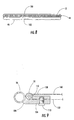
- An end view of an assembly panel 12 employing a sliding track fastener 44 is shown in FIG. 8. If desired, a cover may be positioned over the closed fastener 44 for aesthetics. Suitable methods for sealing the fastener ends 64, 66 include application of heat to fuse the fastener ends 64, 66 closed, application of an adhesive to adhesively close the fastener ends 64, 66, and use of a staple or any other suitable means for closing the fastener ends 64, 66.
- the sliding track fastener 44 may be fabricated from polyester or some other material that can be fused by application of heat along the entire length of the fastener 44 to further inhibit the ability of the fastener 44 to inadvertently open.
- FIG. 7 Another method for positioning the sub-frame 50 within the envelope 40 can be described with reference to FIG. 7.
- the width of the sub-frame 50 can be reduced by an amount Y so that the width of the sub-frame 50 becomes W - Y.
- the deformed sub-frame 50 is then slipped in the envelope 40, the sub-frame 50 is released so that the envelope periphery urges against the sub-frame 50, and the fastener 44 is closed to envelop the sub-frame within the envelope 40. If using a sliding track fastener 44, the ends 64, 66 of the fastener 44 are then removed and sealed in accordance with the immediately preceding description.
- the envelope 40 is stretched to allow insertion of the sub-frame 50.
- the deformed envelope 40 is then released so that the periphery of the envelope urges against the sub-frame 50, and the fastener is closed to envelop the sub-frame within the envelope 40. If using a sliding track fastener 44, the ends 64, 66 of the fastener 44 are then removed and sealed in accordance with the above description.
- each tension zone represents a tension on the resilient material of the envelope 40 that is different than the tension represented by each immediately adjacent tension zone.
- tension zone 20 of the assembled panel 12 will have a tension of about 10 pounds per inch (1751.27 N/m) or less
- tension zone 22 will have a tension of about 65 pounds (11383.26 N/m) per inch
- tension zone 24 will have a tension within the range of about 30-35 pounds per inch (5253.81 - 6129.45 N/m) or less
- tension zone 26 will have a tension of about 65 pounds per inch (11,383.26 N/m)
- tension zone 28 will have a tension of about 10 pounds per inch (1751.27 N/m) or less, with each of these tensions being applied in a common direction (i.e., for the envelope 40 of FIG. 3, in a direction substantially parallel with end 46).
- the use of multiple tension zones 20-28 in the panel 12 eliminates the need for additional support structure beneath or behind the high tension areas with little or no detrimental effect to the occupant's comfort.
- the assembled panel 12 includes a top layer 100 of resilient material in opposed relation to a bottom layer 102 of resilient material with the bottom layer 102 providing overload support in the event the top layer 100 receives sufficient loading to bring it into contact with the bottom layer 102.
- the two layers 100, 102 complement one another and provide a significant level of redundancy and integrity to the panel 12.
- the assembled panel 12 may be attached to the chair frame 16 in a number of ways.
- FIG. 9 illustrates how the panel 12 can be attached to the chair frame 16 in accordance with a preferred embodiment.
- the attachment assembly employs two plates - a chair plate 104 attached to the chair frame 16 by, for example, a weld 106 and a seat plate 108 attached to the sub-frame 50 by a weld 110.
- the two plates 104, 108 are attached so as to be in alignment with one another when the panel 12 is properly positioned with respect to the chair frame 16. In proper alignment, the two plates 104, 108 are then attached to each other with use of a fastener, such as a threaded bolt 112, weld, adhesive, or other suitable fastener.
- a total of four such plate assemblies are used to secure the panel 12 to the chair frame 16.
Landscapes
- Chair Legs, Seat Parts, And Backrests (AREA)
- Acyclic And Carbocyclic Compounds In Medicinal Compositions (AREA)
- Special Chairs (AREA)
Claims (22)
- Flächenelement (12; 14) umfassend:eine Hülle (40) aus elastischem Material, wobei die Hülle eine Öffnung (42) mit einem Verschluss (44) zum Verschließen der Hülle (40) hat; undeinen Hüllentragrahmen (50), welcher im Wesentlichen steif ist und in einer geschlossenen Schleife ausgebildet ist, wobei der Hüllentragrahmen (50) im Inneren der Hülle (40) angeordnet ist und das elastische Material der Hülle (40) in einer oder mehreren Spannungszonen (20, 22, 24, 26, 28; 30, 32, 34) unter Zugspannung setzt;wobei der Verschluss (44) geschlossen wird, um den Hüllentragrahmen (50) mit dem elastischen Material zu umhüllen;dadurch gekennzeichnet, dass:die eine oder mehreren Spannungszonen (20, 22, 24, 26; 30, 32, 34) eine Mehrzahl von aneinander angrenzenden Spannungszonen (20, 22, 24, 26; 30, 32, 34) umfassen, wobei jede Spannungszone (20, 22, 24, 26; 30, 32, 34) eine Spannung auf das elastische Material verkörpert, welche von der von jeder unmittelbar benachbarten Spannungszone (20, 22, 24, 26; 30, 32, 34) verkörperten Spannung verschieden ist.
- Flächenelement nach Anspruch 1, wobei eine durch jede der Spannungszonen (20, 22, 24, 26; 30, 32, 34) verkörperte Spannung in einer gemeinsamen Richtung auf das elastische Material ausgeübt wird.
- Flächenelement nach Anspruch 1 oder Anspruch 2, wobei die Spannung in einer ersten Spannungszone (22, 26) etwa 65 Pfund pro Zoll (11383,26 N/m) und die Spannung in einer zweiten Spannungszone (20, 28) etwa 10 Pfund pro Zoll (1751,27 N/m) oder weniger beträgt.
- Flächenelement nach Anspruch 1 oder Anspruch 2, wobei die Spannung in einer ersten Spannungszone (22, 26) etwa 65 Pfund pro Zoll (11383,26 N/m) und die Spannung in einer zweiten Spannungszone (24) etwa 35 Pfund pro Zoll (6129,45 N/m) oder weniger beträgt.
- Flächenelement nach einem der Ansprüche 1 bis 4, wobei sich die Breite (W) von jeder Spannungszone (20, 22, 24, 26; 30, 32, 34), wenn die Hülle (40) in ihrem entspannten Zustand ist, von der Breite (W) von jeder unmittelbar benachbarten Spannungszone (20, 22, 24, 26; 30, 32, 34) unterscheidet.
- Flächenelement nach einem der Ansprüche 1 bis 5, ferner umfassend einen Stuhlrahmen (16), welcher an dem Hüllentragrahmen (50) angebracht ist.
- Flächenelement nach Anspruch 1, wobei die Hülle umfasst:eine erste Lage (100) aus dem elastischen Material in gegensätzlicher Beziehung zu einer zweiten Lage (102) aus elastischem Material; undwobei der Hüllentragrahmen (50) jede Lage (100, 102) des elastischen Materials der Hülle (40) in einer oder mehreren Spannungszonen (20, 22, 24, 26) unter Zugspannung setzt;wobei die zweite Lage (102) aus elastischem Material eine Überlastungsabstützung bereitstellt, wenn eine Belastung der ersten Lage aus elastischem Material bewirkt, dass die erste Lage (100) aus elastischem Material die zweite Lage (102) aus elastischem Material berührt.
- Flächenelement nach Anspruch 7, wobei eine durch jede der Spannungszonen (20, 22, 24, 26) verkörperte Spannung in einer gemeinsamen Richtung auf das elastische Material ausgeübt wird.
- Flächenelement nach Anspruch 7 oder Anspruch 8 wobei die Spannung in einer ersten Spannungszone (22, 26) etwa 65 Pfund pro Zoll (11383,26 N/m) und die Spannung in einer zweiten Spannungszone (24) etwa 10 Pfund pro Zoll (1751,27 N/m) oder weniger beträgt.
- Flächenelement nach Anspruch 7 oder Anspruch 8, wobei die Spannung in einer ersten Spannungszone etwa 65 Pfund pro Zoll (11383,26 N/m) und die Spannung in einer zweiten Spannungszone etwa 35 Pfund pro Zoll (6129,45 N/m) oder weniger beträgt.
- Flächenelement nach einem der Ansprüche 7 bis 10, wobei sich die Breite (W) von jeder Spannungszone (20, 22, 24, 26), wenn die Hülle (40) in ihrem entspannten Zustand ist, von der Breite (W) von jeder unmittelbar benachbarten Spannungszone (20, 22, 24, 26) unterscheidet.
- Flächenelement nach einem der Ansprüche 7 bis 11, ferner umfassend einen Stuhlrahmen (16), welcher an dem Hüllentragrahmen (50) angebracht ist.
- Flächenelement (12, 14) nach Anspruch 1, wobei die Mehrzahl von Spannungszonen (20, 22, 24, 26, 28; 30, 32, 34) im wesentlichen parallel sind und wobei jede Spannungszone (20, 22, 24, 26, 28; 30, 32, 34) eine Spannung auf das elastische Material verkörpert, welche von der durch eine andere Spannungszone (20, 22, 24, 26, 28; 30, 32, 34) verkörperten Spannung verschieden ist.
- Flächenelement nach Anspruch 13, wobei die Spannung in einer ersten Spannungszone (20, 22, 24, 26, 28; 30, 32, 34) etwa 65 Pfund pro Zoll (11383,26 N/m) und die Spannung in einer zweiten Spannungszone (20, 22, 24, 26, 28; 30, 32, 34) etwa 10 Pfund pro Zoll (1751,27 N/m) oder weniger beträgt.
- Flächenelement nach Anspruch 13, wobei die Spannung in einer ersten Spannungszone (20, 22, 24, 26, 28; 30, 32, 34) etwa 65 Pfund pro Zoll (11383,26 N/m) und die Spannung in einer zweiten Spannungszone (20, 22, 24, 26, 28; 30, 32, 34) etwa 35 Pfund pro Zoll (6129,45 N/m) oder weniger beträgt.
- Flächenelement nach einem der Ansprüche 13 bis 15, wobei sich die Breite (W) von jeder Spannungszone (20, 22, 24, 26, 28; 30, 32, 34), wenn die Hülle (40) in ihrem entspannten Zustand ist, von der Breite (W) von jeder unmittelbar benachbarten Spannungszone (20, 22, 24, 26, 28; 30, 32, 34) unterscheidet.
- Vorrichtung zur Aufnahme eines Nutzers in einer sitzenden Position,
wobei die Vorrichtung umfasst:einen Sitzrahmen (16); undwenigstens ein Flächenelement (12) nach Anspruch 1, welches an dem Sitzrahmen zum Abstützen eines Nutzers der Vorrichtung angebracht ist. - Vorrichtung nach Anspruch 17, ferner umfassend:eine Sitzplatte (104), welche an dem Sitzrahmen (16) angebracht ist;eine Unterrahmenplatte (108), welche an dem Hüllenunterrahmen (50) angebracht ist; undein Befestigungsmittel (112), um die Unterrahmenplatte (108) an der Sitzplatte (104) anzubringen.
- Vorrichtung nach Anspruch 17, wobei eine durch jede der Spannungszonen (20, 22, 24, 26, 28) verkörperte Spannung in einer gemeinsamen Richtung auf das elastische Material ausgeübt wird.
- Vorrichtung nach Anspruch 17 oder Anspruch 18, wobei die Spannung in einer ersten Spannungszone etwa 65 Pfund pro Zoll (11383,26 N/m) und die Spannung in einer zweiten Spannungszone etwa 10 Pfund pro Zoll (1751,27 N/m) oder weniger beträgt.
- Vorrichtung nach Anspruch 18 oder Anspruch 19, wobei die Spannung in einer ersten Spannungszone etwa 65 Pfund pro Zoll (11383,26 N/m) und die Spannung in einer zweiten Spannungszone etwa 35 Pfund pro Zoll (6129,45 N/m) oder weniger beträgt.
- Vorrichtung nach einem der Ansprüche 17 bis 21, wobei sich die Breite (W) von jeder Spannungszone (20, 22, 24, 26), wenn die Hülle (40) in ihrem entspannten Zustand ist, von der Breite (W) von jeder unmittelbar benachbarten Spannungszone (20, 22, 24, 26) unterscheidet.
Priority Applications (5)
| Application Number | Priority Date | Filing Date | Title |
|---|---|---|---|
| ES03253783T ES2276012T3 (es) | 2003-06-16 | 2003-06-16 | Panel a siento. |
| AT03253783T ATE342680T1 (de) | 2003-06-16 | 2003-06-16 | Sitzfläche |
| DE2003609143 DE60309143T2 (de) | 2003-06-16 | 2003-06-16 | Sitzfläche |
| EP20030253783 EP1488718B1 (de) | 2003-06-16 | 2003-06-16 | Sitzfläche |
| BRPI0601121 BRPI0601121A (pt) | 2003-06-16 | 2006-03-20 | painel de tecido para cadeiras e móveis |
Applications Claiming Priority (2)
| Application Number | Priority Date | Filing Date | Title |
|---|---|---|---|
| EP20030253783 EP1488718B1 (de) | 2003-06-16 | 2003-06-16 | Sitzfläche |
| BRPI0601121 BRPI0601121A (pt) | 2003-06-16 | 2006-03-20 | painel de tecido para cadeiras e móveis |
Publications (2)
| Publication Number | Publication Date |
|---|---|
| EP1488718A1 EP1488718A1 (de) | 2004-12-22 |
| EP1488718B1 true EP1488718B1 (de) | 2006-10-18 |
Family
ID=41277612
Family Applications (1)
| Application Number | Title | Priority Date | Filing Date |
|---|---|---|---|
| EP20030253783 Expired - Lifetime EP1488718B1 (de) | 2003-06-16 | 2003-06-16 | Sitzfläche |
Country Status (5)
| Country | Link |
|---|---|
| EP (1) | EP1488718B1 (de) |
| AT (1) | ATE342680T1 (de) |
| BR (1) | BRPI0601121A (de) |
| DE (1) | DE60309143T2 (de) |
| ES (1) | ES2276012T3 (de) |
Family Cites Families (5)
| Publication number | Priority date | Publication date | Assignee | Title |
|---|---|---|---|---|
| US2108242A (en) * | 1936-11-14 | 1938-02-15 | Wallace Leta | Adjustable cushion |
| US3372406A (en) * | 1965-08-03 | 1968-03-12 | Heckethorn Mfg | Ventilated cushion structure |
| US3736022A (en) * | 1971-07-26 | 1973-05-29 | Oil Products Co | Molded seat cushion with cast skin and insert receiving recess |
| US4062589A (en) * | 1976-08-04 | 1977-12-13 | Klein Gerhart P | Chair with contoured seat |
| CA2342266A1 (en) * | 2000-05-16 | 2001-11-16 | Art Design International Inc. | Articulated seat |
-
2003
- 2003-06-16 ES ES03253783T patent/ES2276012T3/es not_active Expired - Lifetime
- 2003-06-16 EP EP20030253783 patent/EP1488718B1/de not_active Expired - Lifetime
- 2003-06-16 DE DE2003609143 patent/DE60309143T2/de not_active Expired - Lifetime
- 2003-06-16 AT AT03253783T patent/ATE342680T1/de not_active IP Right Cessation
-
2006
- 2006-03-20 BR BRPI0601121 patent/BRPI0601121A/pt not_active IP Right Cessation
Also Published As
| Publication number | Publication date |
|---|---|
| EP1488718A1 (de) | 2004-12-22 |
| BRPI0601121A (pt) | 2006-08-22 |
| ATE342680T1 (de) | 2006-11-15 |
| ES2276012T3 (es) | 2007-06-16 |
| DE60309143T2 (de) | 2007-08-23 |
| DE60309143D1 (de) | 2006-11-30 |
Similar Documents
| Publication | Publication Date | Title |
|---|---|---|
| US6886890B2 (en) | Panel | |
| US7871131B2 (en) | Panel | |
| US7406733B2 (en) | Elastomeric fabric load bearing surface | |
| US4826249A (en) | Thin inflatable elastomeric seat | |
| EP0342790B1 (de) | Elastisches Gewebe zur Sitzfederung | |
| US6820934B2 (en) | Chair having flexible back support | |
| US5855415A (en) | Portable seat cushion having pressure-reducing properties | |
| CA2542703C (en) | Seating structure having flexible support surface | |
| CA2484821C (en) | Multi-layer cushion and cover | |
| US4385783A (en) | Upholstered furniture element | |
| US3070402A (en) | Upholstered seating and furniture | |
| CN102843931A (zh) | 具有波状弹性靠背的座椅结构 | |
| CN100434304C (zh) | 车辆用座椅 | |
| US2231346A (en) | Seat construction | |
| US3501197A (en) | Seat support | |
| US9986839B2 (en) | Banquet chair with outer spring | |
| JP2008284163A (ja) | クッションカバー | |
| EP1488718A1 (de) | Sitzfläche | |
| US3088133A (en) | Foam base for furniture | |
| US3363271A (en) | Furniture base construction | |
| US7144084B2 (en) | Chair with rod frame back assembly | |
| GB2150021A (en) | Improvements in self- supporting moulded furniture frames for upholstered furniture | |
| JP3109026B2 (ja) | ソファ | |
| US3332092A (en) | Form fitting pew cushion | |
| JP2024173913A (ja) | 椅子 |
Legal Events
| Date | Code | Title | Description |
|---|---|---|---|
| PUAI | Public reference made under article 153(3) epc to a published international application that has entered the european phase |
Free format text: ORIGINAL CODE: 0009012 |
|
| 17P | Request for examination filed |
Effective date: 20040206 |
|
| AK | Designated contracting states |
Kind code of ref document: A1 Designated state(s): AT BE BG CH CY CZ DE DK EE ES FI FR GB GR HU IE IT LI LU MC NL PT RO SE SI SK TR |
|
| AX | Request for extension of the european patent |
Extension state: AL LT LV MK |
|
| AKX | Designation fees paid |
Designated state(s): AT BE BG CH CY CZ DE DK EE ES FI FR GB GR HU IE IT LI LU MC NL PT RO SE SI SK TR |
|
| GRAP | Despatch of communication of intention to grant a patent |
Free format text: ORIGINAL CODE: EPIDOSNIGR1 |
|
| GRAS | Grant fee paid |
Free format text: ORIGINAL CODE: EPIDOSNIGR3 |
|
| GRAA | (expected) grant |
Free format text: ORIGINAL CODE: 0009210 |
|
| AK | Designated contracting states |
Kind code of ref document: B1 Designated state(s): AT BE BG CH CY CZ DE DK EE ES FI FR GB GR HU IE IT LI LU MC NL PT RO SE SI SK TR |
|
| PG25 | Lapsed in a contracting state [announced via postgrant information from national office to epo] |
Ref country code: SI Free format text: LAPSE BECAUSE OF FAILURE TO SUBMIT A TRANSLATION OF THE DESCRIPTION OR TO PAY THE FEE WITHIN THE PRESCRIBED TIME-LIMIT Effective date: 20061018 Ref country code: SK Free format text: LAPSE BECAUSE OF FAILURE TO SUBMIT A TRANSLATION OF THE DESCRIPTION OR TO PAY THE FEE WITHIN THE PRESCRIBED TIME-LIMIT Effective date: 20061018 Ref country code: RO Free format text: LAPSE BECAUSE OF FAILURE TO SUBMIT A TRANSLATION OF THE DESCRIPTION OR TO PAY THE FEE WITHIN THE PRESCRIBED TIME-LIMIT Effective date: 20061018 Ref country code: CH Free format text: LAPSE BECAUSE OF FAILURE TO SUBMIT A TRANSLATION OF THE DESCRIPTION OR TO PAY THE FEE WITHIN THE PRESCRIBED TIME-LIMIT Effective date: 20061018 Ref country code: BE Free format text: LAPSE BECAUSE OF FAILURE TO SUBMIT A TRANSLATION OF THE DESCRIPTION OR TO PAY THE FEE WITHIN THE PRESCRIBED TIME-LIMIT Effective date: 20061018 Ref country code: AT Free format text: LAPSE BECAUSE OF FAILURE TO SUBMIT A TRANSLATION OF THE DESCRIPTION OR TO PAY THE FEE WITHIN THE PRESCRIBED TIME-LIMIT Effective date: 20061018 Ref country code: NL Free format text: LAPSE BECAUSE OF FAILURE TO SUBMIT A TRANSLATION OF THE DESCRIPTION OR TO PAY THE FEE WITHIN THE PRESCRIBED TIME-LIMIT Effective date: 20061018 Ref country code: FI Free format text: LAPSE BECAUSE OF FAILURE TO SUBMIT A TRANSLATION OF THE DESCRIPTION OR TO PAY THE FEE WITHIN THE PRESCRIBED TIME-LIMIT Effective date: 20061018 Ref country code: LI Free format text: LAPSE BECAUSE OF FAILURE TO SUBMIT A TRANSLATION OF THE DESCRIPTION OR TO PAY THE FEE WITHIN THE PRESCRIBED TIME-LIMIT Effective date: 20061018 |
|
| REG | Reference to a national code |
Ref country code: GB Ref legal event code: FG4D |
|
| REG | Reference to a national code |
Ref country code: CH Ref legal event code: EP Ref country code: IE Ref legal event code: FG4D |
|
| REF | Corresponds to: |
Ref document number: 60309143 Country of ref document: DE Date of ref document: 20061130 Kind code of ref document: P |
|
| PG25 | Lapsed in a contracting state [announced via postgrant information from national office to epo] |
Ref country code: SE Free format text: LAPSE BECAUSE OF FAILURE TO SUBMIT A TRANSLATION OF THE DESCRIPTION OR TO PAY THE FEE WITHIN THE PRESCRIBED TIME-LIMIT Effective date: 20070118 Ref country code: DK Free format text: LAPSE BECAUSE OF FAILURE TO SUBMIT A TRANSLATION OF THE DESCRIPTION OR TO PAY THE FEE WITHIN THE PRESCRIBED TIME-LIMIT Effective date: 20070118 Ref country code: BG Free format text: LAPSE BECAUSE OF FAILURE TO SUBMIT A TRANSLATION OF THE DESCRIPTION OR TO PAY THE FEE WITHIN THE PRESCRIBED TIME-LIMIT Effective date: 20070118 |
|
| PG25 | Lapsed in a contracting state [announced via postgrant information from national office to epo] |
Ref country code: PT Free format text: LAPSE BECAUSE OF FAILURE TO SUBMIT A TRANSLATION OF THE DESCRIPTION OR TO PAY THE FEE WITHIN THE PRESCRIBED TIME-LIMIT Effective date: 20070319 |
|
| NLV1 | Nl: lapsed or annulled due to failure to fulfill the requirements of art. 29p and 29m of the patents act | ||
| REG | Reference to a national code |
Ref country code: CH Ref legal event code: PL |
|
| ET | Fr: translation filed | ||
| REG | Reference to a national code |
Ref country code: ES Ref legal event code: FG2A Ref document number: 2276012 Country of ref document: ES Kind code of ref document: T3 |
|
| PLBE | No opposition filed within time limit |
Free format text: ORIGINAL CODE: 0009261 |
|
| STAA | Information on the status of an ep patent application or granted ep patent |
Free format text: STATUS: NO OPPOSITION FILED WITHIN TIME LIMIT |
|
| 26N | No opposition filed |
Effective date: 20070719 |
|
| PG25 | Lapsed in a contracting state [announced via postgrant information from national office to epo] |
Ref country code: MC Free format text: LAPSE BECAUSE OF NON-PAYMENT OF DUE FEES Effective date: 20070630 |
|
| PG25 | Lapsed in a contracting state [announced via postgrant information from national office to epo] |
Ref country code: GR Free format text: LAPSE BECAUSE OF FAILURE TO SUBMIT A TRANSLATION OF THE DESCRIPTION OR TO PAY THE FEE WITHIN THE PRESCRIBED TIME-LIMIT Effective date: 20070119 |
|
| PG25 | Lapsed in a contracting state [announced via postgrant information from national office to epo] |
Ref country code: IE Free format text: LAPSE BECAUSE OF NON-PAYMENT OF DUE FEES Effective date: 20070618 |
|
| PG25 | Lapsed in a contracting state [announced via postgrant information from national office to epo] |
Ref country code: EE Free format text: LAPSE BECAUSE OF FAILURE TO SUBMIT A TRANSLATION OF THE DESCRIPTION OR TO PAY THE FEE WITHIN THE PRESCRIBED TIME-LIMIT Effective date: 20061018 |
|
| PG25 | Lapsed in a contracting state [announced via postgrant information from national office to epo] |
Ref country code: LU Free format text: LAPSE BECAUSE OF NON-PAYMENT OF DUE FEES Effective date: 20070616 Ref country code: CY Free format text: LAPSE BECAUSE OF FAILURE TO SUBMIT A TRANSLATION OF THE DESCRIPTION OR TO PAY THE FEE WITHIN THE PRESCRIBED TIME-LIMIT Effective date: 20061018 |
|
| PG25 | Lapsed in a contracting state [announced via postgrant information from national office to epo] |
Ref country code: TR Free format text: LAPSE BECAUSE OF FAILURE TO SUBMIT A TRANSLATION OF THE DESCRIPTION OR TO PAY THE FEE WITHIN THE PRESCRIBED TIME-LIMIT Effective date: 20061018 Ref country code: HU Free format text: LAPSE BECAUSE OF FAILURE TO SUBMIT A TRANSLATION OF THE DESCRIPTION OR TO PAY THE FEE WITHIN THE PRESCRIBED TIME-LIMIT Effective date: 20070419 |
|
| PGFP | Annual fee paid to national office [announced via postgrant information from national office to epo] |
Ref country code: DE Payment date: 20100622 Year of fee payment: 8 Ref country code: GB Payment date: 20100624 Year of fee payment: 8 Ref country code: IT Payment date: 20100630 Year of fee payment: 8 |
|
| PGFP | Annual fee paid to national office [announced via postgrant information from national office to epo] |
Ref country code: CZ Payment date: 20111109 Year of fee payment: 9 Ref country code: ES Payment date: 20111104 Year of fee payment: 9 Ref country code: FR Payment date: 20120106 Year of fee payment: 9 |
|
| REG | Reference to a national code |
Ref country code: DE Ref legal event code: R082 Ref document number: 60309143 Country of ref document: DE Representative=s name: WEICKMANN & WEICKMANN, DE |
|
| REG | Reference to a national code |
Ref country code: DE Ref legal event code: R082 Ref document number: 60309143 Country of ref document: DE Representative=s name: WEICKMANN & WEICKMANN, DE |
|
| REG | Reference to a national code |
Ref country code: DE Ref legal event code: R082 Ref document number: 60309143 Country of ref document: DE Representative=s name: WEICKMANN & WEICKMANN, DE Effective date: 20120509 Ref country code: DE Ref legal event code: R081 Ref document number: 60309143 Country of ref document: DE Owner name: DLR DESIGN, LLC, US Free format text: FORMER OWNER: DAVID L. ROWLAND,ERWIN W. ROWLAND, , US Effective date: 20120507 Ref country code: DE Ref legal event code: R082 Ref document number: 60309143 Country of ref document: DE Representative=s name: WEICKMANN & WEICKMANN, DE Effective date: 20120507 Ref country code: DE Ref legal event code: R081 Ref document number: 60309143 Country of ref document: DE Owner name: DLR DESIGN, LLC, US Free format text: FORMER OWNER: ROWLAND, ERWIN W., MARION, US Effective date: 20120509 Ref country code: DE Ref legal event code: R081 Ref document number: 60309143 Country of ref document: DE Owner name: DLR DESIGN, LLC, MARION, US Free format text: FORMER OWNERS: ROWLAND, DAVID L., MARION, VIRGINIA, US; ROWLAND, ERWIN W., MARION, VIRGINIA, US Effective date: 20120507 Ref country code: DE Ref legal event code: R082 Ref document number: 60309143 Country of ref document: DE Representative=s name: WEICKMANN & WEICKMANN PATENTANWAELTE - RECHTSA, DE Effective date: 20120507 Ref country code: DE Ref legal event code: R081 Ref document number: 60309143 Country of ref document: DE Owner name: DLR DESIGN, LLC, MARION, US Free format text: FORMER OWNER: ROWLAND, ERWIN W., MARION, VIRGINIA, US Effective date: 20120509 Ref country code: DE Ref legal event code: R082 Ref document number: 60309143 Country of ref document: DE Representative=s name: WEICKMANN & WEICKMANN PATENTANWAELTE - RECHTSA, DE Effective date: 20120509 |
|
| PG25 | Lapsed in a contracting state [announced via postgrant information from national office to epo] |
Ref country code: CZ Free format text: LAPSE BECAUSE OF NON-PAYMENT OF DUE FEES Effective date: 20120616 |
|
| GBPC | Gb: european patent ceased through non-payment of renewal fee |
Effective date: 20120616 |
|
| PG25 | Lapsed in a contracting state [announced via postgrant information from national office to epo] |
Ref country code: IT Free format text: LAPSE BECAUSE OF NON-PAYMENT OF DUE FEES Effective date: 20120616 |
|
| REG | Reference to a national code |
Ref country code: FR Ref legal event code: ST Effective date: 20130228 |
|
| PG25 | Lapsed in a contracting state [announced via postgrant information from national office to epo] |
Ref country code: GB Free format text: LAPSE BECAUSE OF NON-PAYMENT OF DUE FEES Effective date: 20120616 Ref country code: DE Free format text: LAPSE BECAUSE OF NON-PAYMENT OF DUE FEES Effective date: 20130101 Ref country code: FR Free format text: LAPSE BECAUSE OF NON-PAYMENT OF DUE FEES Effective date: 20120702 |
|
| REG | Reference to a national code |
Ref country code: DE Ref legal event code: R119 Ref document number: 60309143 Country of ref document: DE Effective date: 20130101 |
|
| REG | Reference to a national code |
Ref country code: ES Ref legal event code: FD2A Effective date: 20131021 |
|
| PG25 | Lapsed in a contracting state [announced via postgrant information from national office to epo] |
Ref country code: ES Free format text: LAPSE BECAUSE OF NON-PAYMENT OF DUE FEES Effective date: 20120617 |