EP1488024B1 - Process and device for forming ceramic coatings on metals and alloys - Google Patents
Process and device for forming ceramic coatings on metals and alloys Download PDFInfo
- Publication number
- EP1488024B1 EP1488024B1 EP02765036.5A EP02765036A EP1488024B1 EP 1488024 B1 EP1488024 B1 EP 1488024B1 EP 02765036 A EP02765036 A EP 02765036A EP 1488024 B1 EP1488024 B1 EP 1488024B1
- Authority
- EP
- European Patent Office
- Prior art keywords
- electrolyte
- current
- process according
- frequency
- acoustic
- Prior art date
- Legal status (The legal status is an assumption and is not a legal conclusion. Google has not performed a legal analysis and makes no representation as to the accuracy of the status listed.)
- Expired - Lifetime
Links
Images

Classifications
-
- C—CHEMISTRY; METALLURGY
- C25—ELECTROLYTIC OR ELECTROPHORETIC PROCESSES; APPARATUS THEREFOR
- C25D—PROCESSES FOR THE ELECTROLYTIC OR ELECTROPHORETIC PRODUCTION OF COATINGS; ELECTROFORMING; APPARATUS THEREFOR
- C25D5/00—Electroplating characterised by the process; Pretreatment or after-treatment of workpieces
- C25D5/60—Electroplating characterised by the structure or texture of the layers
- C25D5/615—Microstructure of the layers, e.g. mixed structure
- C25D5/617—Crystalline layers
-
- C—CHEMISTRY; METALLURGY
- C25—ELECTROLYTIC OR ELECTROPHORETIC PROCESSES; APPARATUS THEREFOR
- C25D—PROCESSES FOR THE ELECTROLYTIC OR ELECTROPHORETIC PRODUCTION OF COATINGS; ELECTROFORMING; APPARATUS THEREFOR
- C25D5/00—Electroplating characterised by the process; Pretreatment or after-treatment of workpieces
- C25D5/18—Electroplating using modulated, pulsed or reversing current
-
- C—CHEMISTRY; METALLURGY
- C25—ELECTROLYTIC OR ELECTROPHORETIC PROCESSES; APPARATUS THEREFOR
- C25D—PROCESSES FOR THE ELECTROLYTIC OR ELECTROPHORETIC PRODUCTION OF COATINGS; ELECTROFORMING; APPARATUS THEREFOR
- C25D11/00—Electrolytic coating by surface reaction, i.e. forming conversion layers
- C25D11/005—Apparatus specially adapted for electrolytic conversion coating
-
- C—CHEMISTRY; METALLURGY
- C25—ELECTROLYTIC OR ELECTROPHORETIC PROCESSES; APPARATUS THEREFOR
- C25D—PROCESSES FOR THE ELECTROLYTIC OR ELECTROPHORETIC PRODUCTION OF COATINGS; ELECTROFORMING; APPARATUS THEREFOR
- C25D11/00—Electrolytic coating by surface reaction, i.e. forming conversion layers
- C25D11/02—Anodisation
- C25D11/024—Anodisation under pulsed or modulated current or potential
-
- C—CHEMISTRY; METALLURGY
- C25—ELECTROLYTIC OR ELECTROPHORETIC PROCESSES; APPARATUS THEREFOR
- C25D—PROCESSES FOR THE ELECTROLYTIC OR ELECTROPHORETIC PRODUCTION OF COATINGS; ELECTROFORMING; APPARATUS THEREFOR
- C25D11/00—Electrolytic coating by surface reaction, i.e. forming conversion layers
- C25D11/02—Anodisation
- C25D11/026—Anodisation with spark discharge
-
- C—CHEMISTRY; METALLURGY
- C25—ELECTROLYTIC OR ELECTROPHORETIC PROCESSES; APPARATUS THEREFOR
- C25D—PROCESSES FOR THE ELECTROLYTIC OR ELECTROPHORETIC PRODUCTION OF COATINGS; ELECTROFORMING; APPARATUS THEREFOR
- C25D5/00—Electroplating characterised by the process; Pretreatment or after-treatment of workpieces
- C25D5/20—Electroplating using ultrasonic waves
-
- C—CHEMISTRY; METALLURGY
- C25—ELECTROLYTIC OR ELECTROPHORETIC PROCESSES; APPARATUS THEREFOR
- C25D—PROCESSES FOR THE ELECTROLYTIC OR ELECTROPHORETIC PRODUCTION OF COATINGS; ELECTROFORMING; APPARATUS THEREFOR
- C25D5/00—Electroplating characterised by the process; Pretreatment or after-treatment of workpieces
- C25D5/60—Electroplating characterised by the structure or texture of the layers
- C25D5/605—Surface topography of the layers, e.g. rough, dendritic or nodular layers
- C25D5/611—Smooth layers
-
- C—CHEMISTRY; METALLURGY
- C25—ELECTROLYTIC OR ELECTROPHORETIC PROCESSES; APPARATUS THEREFOR
- C25D—PROCESSES FOR THE ELECTROLYTIC OR ELECTROPHORETIC PRODUCTION OF COATINGS; ELECTROFORMING; APPARATUS THEREFOR
- C25D5/00—Electroplating characterised by the process; Pretreatment or after-treatment of workpieces
- C25D5/627—Electroplating characterised by the visual appearance of the layers, e.g. colour, brightness or mat appearance
Definitions
- the invention relates to the field of applying protective coatings, and in particular to plasma-electrolytic oxidation coating of articles made of metals and alloys. This process makes it possible rapidly and efficiently to form wear-resistant, corrosion-resistant, heat-resistant, dielectric uniformly-coloured ceramic coatings on the surfaces of these articles.
- the coatings are characterised by a high degree of uniformity of thickness, low surface roughness and the virtual absence of an external porous layer, the removal of which usually involves considerable expense in conventional coating processes.
- the process for producing the coatings and the device for implementing the process, described in this application can be used in engineering, the aircraft and motor vehicle industries, the petrochemical and textiles industries, electronics, medicine and the production of household goods.
- a process for producing a ceramic coating using industrial-frequency 50-60Hz current is known from WO 99/31303 .
- the process enables hard coatings of thickness up to 200 ⁇ m, well-bonded to the substrate, to be formed on the surface of articles made from aluminium alloys.
- the main problem with this process is the formation of a considerable external porous layer of low microhardness and with numerous micro- and macro-defects (pores, micro-cracks, flaky patches).
- the thickness of the defective layer amounts to 25-55% of the total thickness of the ceramic coating, depending on the chemical composition of the alloy being processed and on the electrolysis regimes.
- Expensive precision equipment is used to remove the porous layer. If the article is of complex shape, with surfaces that are difficult for abrasive and diamond tools to reach, the problem of removing the defective layer becomes difficult to solve. This limits the range of application of the process.
- a process for forming ceramic coatings where the current has a modified sine wave form is known from US 5,616,229 .
- This form of current reduces heat stresses in forming the ceramic layer and enables coatings of thickness up to 300 ⁇ m to be applied.
- industrial frequency current is used in this process, which leads to the formation of a relatively thick external porous layer with high surface roughness and relatively high energy costs.
- RU 2077612 for oxidising valve metals and alloys in a pulsed anode-cathode regime, in which positive and negative pulses of a special complex form alternate.
- the duration of the pulses and of the pause between a positive pulse and a negative one is 100-130 ⁇ sec, and the succession frequency is 50Hz.
- the current reaches its maximum (up to 800A/dm 2 ), after which it remains constant for 25-50 ⁇ sec.
- the shorter pulses and far greater pulse powers enable the discharge ignition time to be reduced considerably, and the main reasons for the formation of the defective outer layers are eliminated.
- the pairs of powerful pulses alternate with unjustifiably long pauses, which leads to a low coating formation rate.
- the closest prior art to the proposed invention is the process described in RU 2070942 for oxidation using alternating positive and negative pulses of voltage, amplitude 100-500V and duration 1-10 ⁇ sec, during which, at each of the anode half-periods, high-voltage positive pulses, amplitude 600-1000V and duration 0.1-1 ⁇ sec, are also applied.
- the pulses When the pulses are applied, the total current at that moment rises, which creates favourable conditions for discharges.
- the problem with this process is the use of very short high-voltage positive pulses, which does not make it possible to create discharges of sufficient power. This leads to low productivity of the process, and it is also extremely difficult to implement the proposed process technically for industrial purposes.
- WO 01/81658 discloses a method for obtaining a ceramic coating at the surface of a metal, having semiconductor properties, such as aluminium, titanium, magnesium, hafnium, zirconium and their alloys, by physico-chemical reaction transforming the treated metal.
- Said method consists in immersing the metallic piece to be coated in an electrolytic solution consisting of an aqueous solution of alkali metal hydroxide, such as potassium or sodium, and an alkali metal oxyacid salt, the metallic piece forming one of the electrodes, and in applying to the electrodes a signal generally triangular in shape, that is having at least a front slope and a rear slope, with variable shape factor during the process, generating a current controlled in intensity, its shape and its ratio between positive intensity and negative intensity.
- an electrolytic solution consisting of an aqueous solution of alkali metal hydroxide, such as potassium or sodium, and an alkali metal oxyacid salt
- Ceramic coatings formed by the process of the first aspect of the present invention may, without any post-processing, have an external porous layer comprising not more than 14% of a total coating thickness.
- Ceramic coatings formed by the process of the first aspect of the present invention may, without any post-processing, have a surface with a low roughness (Ra) of 0.6 to 2.1 ⁇ m.
- the bipolar current pulses may be alternating pulses, or may be supplied as packets of pulses, for example comprising two of one polarity followed by another of opposed polarity.
- Embodiments of the present invention seek to improve the useful properties of ceramic coatings such as resistance to wear, corrosion and heat, and dielectric strength, by improving the physico-mechanical characteristics of the coatings. Embodiments of the invention also solve the technical problem of producing hard microcrystalline ceramic coatings with good adhesion to a substrate.
- Embodiments of the invention also seek to improve the technical sophistication of the process of forming ceramic coatings by significantly reducing the time it takes to apply the coating itself, and the time spent in the finishing treatment thereof. Not only is the productivity of the oxidation process raised, but specific power costs are also significantly reduced.
- Embodiments of the invention additionally provide for the targeted formation of coatings with set properties by introducing refractory inorganic compounds into the electrolyte.
- Embodiments of the invention may also raise the stability of the electrolyte and increase its useful life.
- Embodiments of the apparatus of the present invention seek to provide improved reliability, versatility and ease of building into automated production lines.
- an article to be coated is connected to an electrode and placed in an electrolytic bath which has another electrode and which is filled with an alkaline electrolyte.
- the electrodes are supplied with pulsed current so as to form a coating of a required thickness in a plasma-electrolytic oxidation regime.
- Pulsed current is created in the bath with a pulse succession frequency of 500Hz or more, preferably 1000 to 10,000Hz, with a preferred pulse duration of 20 to 1,000 ⁇ sec.
- Each current pulse advantageously has a steep front, so that the maximum amplitude is reached in not more than 10% of the total pulse duration, and the current then falls sharply, after which it gradually decreases to 50% or less of the maximum.
- the current density is preferably 3 to 200 A/dm 2 , even more preferably 10 to 60A/dm 2 .
- the acoustic vibrations may be generated in the electrolyte by an aerohydrodynamic generator, the generator creating acoustic vibrations in the bath in a sonic frequency range that overlaps with a current pulse frequency range.
- Ultra-disperse powders of oxides, borides, carbides, nitrides, silicides and sulphides of metals of particle size not more than 0.5 ⁇ m may be added to the electrolyte, and a stable hydrosol may be formed with the aid of the acoustic vibrations.
- the relatively brief current pulses reduce the discharge spark time, which makes it possible to carry out oxidation at higher current densities of 3 to 200A/dm 2 .
- the properties of the plasma discharges themselves in high-frequency pulse regimes differ from those of the discharges obtained for oxidation at conventional industrial frequency (50 or 60Hz).
- An increase in the brightness and decrease in the size of the sparks can be observed visually. Instead of sparks moving over the surface being oxidised, numerous sparks are seen to be discharging simultaneously over the entire surface.
- the preferred form of the current pulses ( Figure 1 ) facilitates the uniform initiation and maintenance of plasma discharges over the entire surface of the article.
- the plasma discharge processes do not require a constant high current value to be maintained.
- the steep front of the pulse and its rapid build-up to a maximum make possible a radical reduction in discharge initiation time.
- the current reduced to 50% or less of the maximum, enables the discharge process to be maintained efficiently.
- the steep front of the positive and negative pulses makes it possible rapidly to charge and discharge the capacitive load created both by the electrode system (bath-electrolyte-article), and by the double electric layer on the surface of the article being oxidised (electrolyte-oxide-metal).
- EP 1 042 178 for anodising non-ferrous alloys, in which vibratory agitation of the electrolyte is carried out by a vibro-motor and rotating blades, the electrodes being vibrated and rocked and a supply of compressed air being fed through a porous ceramic tube with pore size 10-400 ⁇ m.
- This enables the anodising process to be conducted at a relatively high current density of 10 to 15A/dm 2 , considerably reducing the anodising time.
- this process is not efficient enough for plasma oxidation, since the rate at which relatively large air bubbles form in the electrolyte, and the frequency of the vibrations in the electrolyte, are low.
- the agitation of the electrolyte and the supply and removal of reagents in the electrode regions take place at the macro level. Furthermore, the technical implementation of this process is difficult from the design point of view.
- WO 96/38603 describes a process for spark oxidation with ultrasonic vibrations acting on the electrolyte. These vibrations facilitate the intensive renewal of the electrolyte in the discharge zone.
- ultrasonic vibrations in a liquid cause degassing and the coalescence of gas bubbles, which float to the surface. Up to 60% of the dissolved gas is separated out from the liquid in the first minute.
- the high power of the ultrasonic vibrations leads to cavitational surface erosion and destroys the ceramic surface, increasing the number of micro-cracks and pores due to hydraulic shocks as the cavitation bubbles burst.
- embodiments of the present invention relate to the formation of ceramic coatings in an alkaline electrolyte in a field of acoustic vibrations within a sonic (i.e. not ultrasonic) frequency range, the intensity of the vibrations preferably not exceeding 1W/cm 2 .
- the acoustic vibrations may be generated by at least one aerohydrodynamic generator, which is an instrument that converts kinetic energy of a jet of liquid and air into acoustic vibration energy.
- aerohydrodynamic generator which is an instrument that converts kinetic energy of a jet of liquid and air into acoustic vibration energy.
- Such generators are distinguished by their simplicity, reliability and economy, and comprise a fluid inlet and a resonance chamber. Acoustic vibrations are induced in the resonance chamber of the generator as the electrolyte passes through it from the fluid inlet, followed by discharge of the electrolyte, as a result of which air from atmosphere is drawn into the generator via a special channel, mixed with the electrolyte and dispersed.
- the efficient removal of the heat created by the plasma discharges eliminates local overheating and ensures the formation of a good-quality ceramic coating of uniform thickness.
- the input of new portions of electrolyte with higher oxygen content intensifies the plasma-chemical reactions in the discharge zone and speeds up the coating formation process.
- the aqueous alkaline electrolytes used for plasma oxidation consist of colloid solutions, i.e. hydrosols. Like any colloid solutions, the electrolytes are liable to coagulation, flocculation and sedimentation. When the electrolyte has reached a certain level of coagulation, flocculation and sedimentation, it becomes ineffective and the quality of the coating deteriorates sharply. Thus, the effectiveness of the electrolyte may be determined by controlling the number and size of the colloid particles.
- Embodiments of the present invention enable the electrolyte to remain stable and efficient for a long time, due to the continuous breaking up of large particles that may form therein.
- the rate of displacement of the colloid particles increases and the number of active collisions of particles with each other, with the walls of the bath and with the surface of the article being oxidised rises, leading to dispersal of the particles.
- ultra-disperse insoluble powders preferably with particle size not more than 0.5 ⁇ m, in some embodiments not more than 0.3 ⁇ m, and a preferred concentration of 0.1 to 5 grams per litre, may be added to the electrolyte.
- This invention proposes the use of nanopowders, preferably with particle size up to 0.5 ⁇ m, in some embodiments up to 0.3 ⁇ m, a developed specific surface (not less than 10m 2 per gram) and which are distinguished by their high-energy state.
- the electrolyte, with the powders introduced into it with the aid of the acoustic vibrations, is brought to a state of a high-disperse stable hydrosol.
- the ultra-dispersed particles themselves are more resistant to coagulation and sedimentation.
- the use of acoustic vibrations causes further dispersion of the particles in the electrolyte and distributes them uniformly within the volume of the electrolyte.
- the acoustic effect intensifies the mixing of the particles and imparts to them an additional quantity of energy. Due to the additional charge carried by the microparticles (they are charged by the ions of the electrolyte), a plasma-chemical reaction is activated in the discharge zone. The ultra-disperse particles entering the plasma discharge zone are partly sublimated and partly completely melted in with the growing oxide layer, forming a dense ceramic coating. The process of forming the coating is also accelerated and may reach 2-10 ⁇ m per minute, depending on the material of the substrate.
- the coatings produced are characterised by high structural stability and uniformity of thickness.
- oxides Al 2 O 3 , ZrO 2 , CeO 2 , CrO 3 , MgO, SiO 2 , TiO 2 , Fe 2 O 3 , Y 2 O 3 , and also mixtures thereof, compound oxides and spinels
- borides ZrB 2 , TiB 2 , CrB 2 , LaB 2
- nitrides Si 3 N 4 , TiN, AlN, BN
- carbides B 4 C, SlC, Cr 3 C 2 , TlC, ZrC, TaC, VC, WC
- sulphides MoS 2 , WS 2 , ZnS, CoS
- silicides WSi 2 , MoSi 2
- others oxides (Al 2 O 3 , ZrO 2 , CeO 2 , CrO 3 , MgO, SiO 2 , TiO 2 , Fe 2 O 3 , Y 2 O 3 , and also mixtures thereof, compound oxides and spinels)
- borides
- nanopowders makes it possible to achieve high quality coatings at relatively low concentrations of 0.1 to 5 grams per litre, preferably 0.5-3g/l. No noticeable effect is produced by the use of higher concentrations or of powders with particle size greater than 0.5 ⁇ m.
- One feature of this invention is a considerable acceleration of the formation of a good quality ceramic coating if the oxidation process is combined with the use of high-frequency electrical pulses and the generation in the electrolyte of acoustic vibrations in the sonic frequency range.
- the acoustic vibration range must overlap with the current pulse frequency range. This increase in the rate of formation of the coating takes place without a significant increase in electricity consumption.
- the device of the present invention for forming ceramic coatings on metals and alloys includes a supply source and an electrolytic bath ( Figure 2 ).
- the supply source produces and supplies to the electrodes electrical pulses of alternating polarity. Positive and negative pulses of current can be sent alternately, one after the other or in alternating packs of pulses.
- the order and frequency of succession of the pulses, their duration and the current and voltage amplitudes may be regulated by a microprocessor, which controls the electrolysis process.
- the electrolytic bath in turn may consist of the bath itself, made for example of stainless steel and serving as one electrode, a second electrode to which the article being oxide-coated is connected, a cooling system for the electrolyte and a system for generating acoustic vibrations.
- the bath may be filled with an alkaline electrolyte of pH 8.5 to 13.5.
- the electrolyte cooling system may consist of a pump to pump the electrolyte, a coarse cleaning filter to trap particles of size more than 10 ⁇ m, and a cooler.
- the temperature of the electrolyte is preferably kept within the limits 15 to 55°C during oxidation.
- the system for generating acoustic vibrations in the electrolyte may consist of an aerohydrodynamic generator (or several of them) fitted in the bath, a pressure gauge and valves regulating the intensity of a supply of the electrolyte and air to the generator.
- the parameters of the acoustic field in the electrolyte are regulated by altering the pressure of the flow of the electrolyte at the input of the aerohydrodynamic generator.
- the generator requires virtually no additional energy and is operated by the pressure of the jet of electrolyte driven by the pump, which may provide pressure from three to seven bars.
- a considerable advantage of the process of embodiments of the present invention is the fact that it makes it possible to produce dense microcrystalline ceramic coatings of thickness up to 150 ⁇ m, preferably from 2 to 150 ⁇ m, and microhardness 500 to 2100HV on metals in a relatively short time (from a few minutes to one hour).
- the coatings have low roughness, Ra 0.6 to 2.1 ⁇ m, and a very thin external porous layer, comprising not more than 14% of the total thickness of the coating. This eliminates, or significantly reduces, the need for subsequent laborious finishing of the surface ( Figure 3 ).
- the coatings are characterised by high uniformity of thickness, even on articles of complex shape.
- the highly dispersed polycrystalline ceramic coatings consist of melted globules, up to several microns in size, firmly bonded to each other.
- This structure produces high physico-mechanical properties in the coatings, such as resistance to wear and corrosion, and dielectric strength.
- the addition to the electrolyte of solid nanopowders of a specific chemical composition provides for targeted changes in the structure, microhardness, strength and colour of the coatings, optimising the properties of the coatings for specific application conditions.
- Embodiments of the present invention enable a ceramic coating to be formed at a rate of 2 to 10 ⁇ m/min, which considerably exceeds the rate of formation of hard ceramic coatings by known prior art processes.
- Figure 1 shows a preferred form of the time dependence of the form of the current pulses (positive and negative) passing in the circuit between the supply source and the electrolytic bath.
- Each current pulse has a steep front, so that the maximum amplitude is reached in not more than 10% of the total pulse duration, and the current then falls sharply, after which it gradually decreases to 50% or less of the maximum.
- the device consists of two parts: an electrolytic bath (1) and a supply source (12), connected to each other by electrical busbars (15, 16).
- the electrolytic bath (1) in turn, consists of a bath (2) of stainless steel, containing an alkaline electrolyte (3) and at least one article (4) immersed in the electrolyte.
- the bath is supplied with a transfer pump (5) and a filter (6) for coarse cleaning of the electrolyte.
- An aerohydrodynamic generator (7) is fitted in the lower part of the bath (2).
- a valve (8) is provided to regulate the pressure of the electrolyte (3), and thus the frequency of the acoustic vibrations.
- a regulating valve (8) and a pressure gauge (9) are fitted at an input to the generator (7).
- a valve (10) is provided to regulate the flow rate of the air going to the generator (7).
- the electrolyte circulating system includes a heat exchanger or cooler (11) to maintain the required temperature of the electrolyte (3) in the course of oxidation.
- the supply source (12) consists of a three-phase pulse generator (13) fitted with a microprocessor (14) controlling the electrical parameters of the oxidation process.
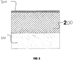
- Figure 3 shows a cross section of a ceramic coating formed on a metal substrate (100).
- the ceramic coating consists of a hard functional layer (200) and a thin (less than 14% of the total coating thickness) external porous layer (300).
- the surface of the ceramic coating has low roughness (Ra 0.6 to 2.1 ⁇ m).
- the invention is clarified by examples of the implementation of the process.
- the specimens to be coated were in the form of a disc 40mm in diameter and 6mm thick.
- the specimens were degreased before oxidation. After oxidation, the specimens were washed in de-ionised water and dried at 100°C for 20 minutes.
- the electrical parameters of the process were registered by an oscilloscope.
- the quality parameters of the coating were measured from transverse micro-sections.
- a specimen of aluminium alloy 2014 was oxidised for 35 minutes in phosphate-silicate electrolyte, pH 11, at temperature 40°C. Bipolar alternating electrical pulses of frequency 2500Hz were supplied to the bath. The current density was 35A/dm 2 , and the final voltage (amplitude) was: anode 900V, cathode 400V. Acoustic vibrations were generated in the bath by an aerohydrodynamic generator. The pressure of the electrolyte at the input into the generator was 4.5 bars. A dense coating of a dark grey colour, overall thickness 130 ⁇ 3 ⁇ m, including an external porous layer 14 ⁇ m thick, was obtained. The roughness of the oxide-coated surface was Ra 2.1 ⁇ m, its microhardness was 1900HV, and the porosity of the hard functional layer (not the external porous layer) was 4%.
- a specimen of magnesium alloy AZ91 was oxidised for two minutes in a phosphate-aluminate electrolyte to which 2g/l of ultra-disperse Al 2 O 3 powder with particle size 0.2 ⁇ m was added.
- the temperature of the electrolyte was 25°C, pH 12.5.
- Bipolar alternating electrical pulses of frequency 10,000Hz were supplied to the bath in turn.
- the current density was 10A/dm 2 and the final voltage (amplitude) was: anode 520V, cathode 240V.
- Acoustic vibrations were generated in the bath using an aerohydrodynamic generator.
- the pressure of the electrolyte at the input to the generator was 4.8 bars.
- the coating obtained was dense, of a white colour, overall thickness 20 ⁇ 1 ⁇ m, including an external porous layer of thickness 2 ⁇ m.
- the roughness of the oxidised surface was Ra 0.8 ⁇ m
- the microhardness of the coating was 600HV
- the porosity of the functional layer was 6%.
- a specimen of titanium alloy Ti Al6 V4 was oxidised for seven minutes in a phosphate-borate electrolyte to which 2g/l of ultra-disperse Al 2 O 3 with particle size 0.2 ⁇ m was added.
- the temperature of the electrolyte was 20°C, pH 9.
- Bipolar alternating electrical pulses of frequency 1,000Hz were supplied to the bath.
- the current density was 60A/dm 2 and the final voltage (amplitude) was: anode 500V, cathode 180V.
- Acoustic vibrations were generated in the bath using an aerohydrodynamic generator.
- the pressure of the electrolyte at the input to the generator was 4.0 bars.
- the coating obtained was dense, of a bluish-grey colour, overall thickness 15 ⁇ 1 ⁇ m, including an external porous layer of thickness 2 ⁇ m.
- the roughness of the oxidised surface was Ra 0.7 ⁇ m
- the microhardness of the coating was 750HV
- the porosity of the functional layer was 2%.
- the coating obtained was dense, of a light grey colour, overall thickness 65 ⁇ 2 ⁇ m, including an external porous layer of thickness 8 ⁇ m.
- the roughness of the oxidised surface was Ra 1.2 ⁇ m
- the microhardness of the coating was 900HV
- the porosity of the functional layer was 5%.
- the coating obtained was dense, of a dark grey colour, overall thickness 25 ⁇ 1 ⁇ m, including an external porous layer of thickness 2.5 ⁇ m.
- the roughness of the oxidised surface was Ra 1.0 ⁇ m
- the microhardness of the coating was 850HV
- the porosity of the functional layer was 5%.
- Bipolar electrical pulses one positive and two negative
- the current density was 50A/dm 2 and the final voltage (amplitude) was: anode 630V, cathode 260V.
- Acoustic vibrations were generated in the bath using an aerohydrodynamic generator.
- the pressure of the electrolyte at the input to the generator was 6.8 bars.
- the coating obtained was dense, white in colour, overall thickness 30 ⁇ 1 ⁇ m, including an external porous layer of thickness 3 ⁇ m.
- the roughness of the oxidised surface was Ra 0.9 ⁇ m
- the microhardness of the coating was 700HV
- the porosity of the functional layer was 3%.
- Table 1 also includes data from a known process of oxidising with industrial-frequency currents.
Landscapes
- Chemical & Material Sciences (AREA)
- Engineering & Computer Science (AREA)
- Chemical Kinetics & Catalysis (AREA)
- Electrochemistry (AREA)
- Materials Engineering (AREA)
- Metallurgy (AREA)
- Organic Chemistry (AREA)
- Crystallography & Structural Chemistry (AREA)
- Other Surface Treatments For Metallic Materials (AREA)
- Electroplating Methods And Accessories (AREA)
Description
- The invention relates to the field of applying protective coatings, and in particular to plasma-electrolytic oxidation coating of articles made of metals and alloys. This process makes it possible rapidly and efficiently to form wear-resistant, corrosion-resistant, heat-resistant, dielectric uniformly-coloured ceramic coatings on the surfaces of these articles.
- The coatings are characterised by a high degree of uniformity of thickness, low surface roughness and the virtual absence of an external porous layer, the removal of which usually involves considerable expense in conventional coating processes.
- The process for producing the coatings and the device for implementing the process, described in this application, can be used in engineering, the aircraft and motor vehicle industries, the petrochemical and textiles industries, electronics, medicine and the production of household goods.
- A process for producing a ceramic coating using industrial-frequency 50-60Hz current is known from
WO 99/31303 - The main problem with this process is the formation of a considerable external porous layer of low microhardness and with numerous micro- and macro-defects (pores, micro-cracks, flaky patches). The thickness of the defective layer amounts to 25-55% of the total thickness of the ceramic coating, depending on the chemical composition of the alloy being processed and on the electrolysis regimes.
- Expensive precision equipment is used to remove the porous layer. If the article is of complex shape, with surfaces that are difficult for abrasive and diamond tools to reach, the problem of removing the defective layer becomes difficult to solve. This limits the range of application of the process.
- Other problems with the known process are the relatively low rate at which the coating forms and the high energy consumption. It is not possible to increase the productivity of the oxidation process simply by raising the current density to higher than 20A/dm2, since the process then becomes an arc process rather than a spark one; and due to the appearance of strong local burn-through discharges, the whole coating becomes very porous and flaky and adhesion to the substrate deteriorates.
- With the aim of intensifying the oxidation process and improving the characteristics of the ceramic coatings, many researchers have tried to improve the electrolysis pulse regimes, proposing different forms and durations of current or voltage pulses.
- A process for forming ceramic coatings where the current has a modified sine wave form is known from
US 5,616,229 . This form of current reduces heat stresses in forming the ceramic layer and enables coatings of thickness up to 300µm to be applied. However, industrial frequency current is used in this process, which leads to the formation of a relatively thick external porous layer with high surface roughness and relatively high energy costs. - There is another known process,
RU 2077612 - There is also a known process,
SU 1767043 - The closest prior art to the proposed invention is the process described in
RU 2070942 -
WO 01/81658 - According to a first aspect of the present invention, there is provided a process for forming ceramic coatings on metals and alloys in an electrolytic bath as defined in claim 1 of the appended claims.
- According to a second aspect of the present invention, there is provided an apparatus for forming a ceramic coating on metals and alloys as defined in
claim 13 of the appended claims. - Ceramic coatings formed by the process of the first aspect of the present invention may, without any post-processing, have an external porous layer comprising not more than 14% of a total coating thickness.
- Ceramic coatings formed by the process of the first aspect of the present invention may, without any post-processing, have a surface with a low roughness (Ra) of 0.6 to 2.1µm.
- The bipolar current pulses may be alternating pulses, or may be supplied as packets of pulses, for example comprising two of one polarity followed by another of opposed polarity.
- Embodiments of the present invention seek to improve the useful properties of ceramic coatings such as resistance to wear, corrosion and heat, and dielectric strength, by improving the physico-mechanical characteristics of the coatings. Embodiments of the invention also solve the technical problem of producing hard microcrystalline ceramic coatings with good adhesion to a substrate.
- Embodiments of the invention also seek to improve the technical sophistication of the process of forming ceramic coatings by significantly reducing the time it takes to apply the coating itself, and the time spent in the finishing treatment thereof. Not only is the productivity of the oxidation process raised, but specific power costs are also significantly reduced.
- Embodiments of the invention additionally provide for the targeted formation of coatings with set properties by introducing refractory inorganic compounds into the electrolyte.
- Embodiments of the invention may also raise the stability of the electrolyte and increase its useful life.
- Embodiments of the apparatus of the present invention seek to provide improved reliability, versatility and ease of building into automated production lines.
- Advantageously, an article to be coated is connected to an electrode and placed in an electrolytic bath which has another electrode and which is filled with an alkaline electrolyte. The electrodes are supplied with pulsed current so as to form a coating of a required thickness in a plasma-electrolytic oxidation regime. Pulsed current is created in the bath with a pulse succession frequency of 500Hz or more, preferably 1000 to 10,000Hz, with a preferred pulse duration of 20 to 1,000µsec. Each current pulse advantageously has a steep front, so that the maximum amplitude is reached in not more than 10% of the total pulse duration, and the current then falls sharply, after which it gradually decreases to 50% or less of the maximum. The current density is preferably 3 to 200 A/dm2, even more preferably 10 to 60A/dm2.
- The acoustic vibrations may be generated in the electrolyte by an aerohydrodynamic generator, the generator creating acoustic vibrations in the bath in a sonic frequency range that overlaps with a current pulse frequency range.
- Ultra-disperse powders (nanopowders) of oxides, borides, carbides, nitrides, silicides and sulphides of metals of particle size not more than 0.5µm may be added to the electrolyte, and a stable hydrosol may be formed with the aid of the acoustic vibrations.
- The relatively brief current pulses reduce the discharge spark time, which makes it possible to carry out oxidation at higher current densities of 3 to 200A/dm2.
- Brief pulses with high current values make it possible to create sparks in plasma discharge channels formed in the coating which are considerably higher in power than for low-frequency regimes. The higher temperatures in the plasma discharge channels, along with the more rapid cooling and solidifying of the molten substrate due to decreased micro-volumes, leads to the formation of dense microcrystalline ceramic coatings with a high content of solid high-temperature oxide phases. The microhardness of the coatings may reach 500 to 2100HV, and the thickness of the external porous layer preferably does not exceed 14% of the total thickness of the coating.
- The use of current pulses with a succession frequency of more than 500Hz and of duration less than 1,000µsec helps to limit the development of arc discharges which make the coating flaky and porous, and at the same time helps to reduce the specific energy costs for forming the coating. However, as the pulse frequency increases, though the specific energy costs are reduced, losses due to surface and capacitive effects begin to rise. These losses start to become significant at a pulse frequency of more than 10,000Hz. Furthermore, the use of current pulses with frequency more than 10,000Hz and duration less than 20µsec requires very high power in the pulse to produce good quality coatings, which it is extremely complicated and expensive to implement technically for industrial purposes.
- The properties of the plasma discharges themselves in high-frequency pulse regimes differ from those of the discharges obtained for oxidation at conventional industrial frequency (50 or 60Hz). An increase in the brightness and decrease in the size of the sparks can be observed visually. Instead of sparks moving over the surface being oxidised, numerous sparks are seen to be discharging simultaneously over the entire surface.
- The preferred form of the current pulses (
Figure 1 ) facilitates the uniform initiation and maintenance of plasma discharges over the entire surface of the article. The plasma discharge processes do not require a constant high current value to be maintained. The steep front of the pulse and its rapid build-up to a maximum make possible a radical reduction in discharge initiation time. The current, reduced to 50% or less of the maximum, enables the discharge process to be maintained efficiently. - Furthermore, the steep front of the positive and negative pulses makes it possible rapidly to charge and discharge the capacitive load created both by the electrode system (bath-electrolyte-article), and by the double electric layer on the surface of the article being oxidised (electrolyte-oxide-metal).
- In practice, during oxidation, mechanical mixers and aerators may be used to agitate the electrolyte, the aerators doing so by bubbling air or oxygen through the electrolyte. These machines create directed flows of liquid, which level out the concentration and temperature of the electrolyte at the macro level. In this sort of mixing, it is difficult to eliminate dead zones and zones of intensive flow round the surface of the article. Modern systems with mixing nozzles ejecting the electrolyte mix it more effectively, ensuring high flow turbulence. Vibratory and pulsating agitation of the electrolyte may also be used.
- There is a known process,
EP 1 042 178 , for anodising non-ferrous alloys, in which vibratory agitation of the electrolyte is carried out by a vibro-motor and rotating blades, the electrodes being vibrated and rocked and a supply of compressed air being fed through a porous ceramic tube with pore size 10-400µm. This enables the anodising process to be conducted at a relatively high current density of 10 to 15A/dm2, considerably reducing the anodising time. However, this process is not efficient enough for plasma oxidation, since the rate at which relatively large air bubbles form in the electrolyte, and the frequency of the vibrations in the electrolyte, are low. The agitation of the electrolyte and the supply and removal of reagents in the electrode regions take place at the macro level. Furthermore, the technical implementation of this process is difficult from the design point of view. - For such a high energy consumption process as plasma electrolytic oxidation, the most significant role is played by the rates of heat and mass transfer and the conditions of the flow of the agitated liquid at the micro level in the direct vicinity of the surface being treated. Acting acoustically on the electrolyte helps to produce this type of agitation.
-
WO 96/38603 - In contrast, embodiments of the present invention relate to the formation of ceramic coatings in an alkaline electrolyte in a field of acoustic vibrations within a sonic (i.e. not ultrasonic) frequency range, the intensity of the vibrations preferably not exceeding 1W/cm2.
- The acoustic vibrations may be generated by at least one aerohydrodynamic generator, which is an instrument that converts kinetic energy of a jet of liquid and air into acoustic vibration energy. Such generators are distinguished by their simplicity, reliability and economy, and comprise a fluid inlet and a resonance chamber. Acoustic vibrations are induced in the resonance chamber of the generator as the electrolyte passes through it from the fluid inlet, followed by discharge of the electrolyte, as a result of which air from atmosphere is drawn into the generator via a special channel, mixed with the electrolyte and dispersed.
- Many micro-bubbles of air are caught up in the flow, filling the entire volume of the bath. The air dissolves intensively in the electrolyte and saturates it with oxygen. The gas saturation of the electrolyte increases by 20-30%.
- The air bubbles, vibrating at the frequency of the acoustic vibrations, create micro-scale flows in the electrolyte, which significantly speeds up the process of agitating the electrolyte, preventing it from becoming depleted close to the surface being oxidised. The efficient removal of the heat created by the plasma discharges eliminates local overheating and ensures the formation of a good-quality ceramic coating of uniform thickness. The input of new portions of electrolyte with higher oxygen content intensifies the plasma-chemical reactions in the discharge zone and speeds up the coating formation process.
- The aqueous alkaline electrolytes used for plasma oxidation consist of colloid solutions, i.e. hydrosols. Like any colloid solutions, the electrolytes are liable to coagulation, flocculation and sedimentation. When the electrolyte has reached a certain level of coagulation, flocculation and sedimentation, it becomes ineffective and the quality of the coating deteriorates sharply. Thus, the effectiveness of the electrolyte may be determined by controlling the number and size of the colloid particles.
- Embodiments of the present invention enable the electrolyte to remain stable and efficient for a long time, due to the continuous breaking up of large particles that may form therein. Under the influence of the acoustic field created by the acoustic vibration generator, the rate of displacement of the colloid particles increases and the number of active collisions of particles with each other, with the walls of the bath and with the surface of the article being oxidised rises, leading to dispersal of the particles.
- To produce ceramic coatings with predetermined functional properties (resistance to wear, light, corrosion and heat, dielectric, uniform colour throughout the thickness), ultra-disperse insoluble powders (nanopowders), preferably with particle size not more than 0.5µm, in some embodiments not more than 0.3µm, and a preferred concentration of 0.1 to 5 grams per litre, may be added to the electrolyte.
- There are known processes for using solid disperse powders in electrolytic spark oxidation (
GB 2237030 WO 97/03231 US 5,616,229 ;RU 2038428 RU 2077612 - This invention proposes the use of nanopowders, preferably with particle size up to 0.5µm, in some embodiments up to 0.3µm, a developed specific surface (not less than 10m2 per gram) and which are distinguished by their high-energy state. The electrolyte, with the powders introduced into it with the aid of the acoustic vibrations, is brought to a state of a high-disperse stable hydrosol.
- The ultra-dispersed particles themselves are more resistant to coagulation and sedimentation. However, the use of acoustic vibrations causes further dispersion of the particles in the electrolyte and distributes them uniformly within the volume of the electrolyte.
- The acoustic effect intensifies the mixing of the particles and imparts to them an additional quantity of energy. Due to the additional charge carried by the microparticles (they are charged by the ions of the electrolyte), a plasma-chemical reaction is activated in the discharge zone. The ultra-disperse particles entering the plasma discharge zone are partly sublimated and partly completely melted in with the growing oxide layer, forming a dense ceramic coating. The process of forming the coating is also accelerated and may reach 2-10µm per minute, depending on the material of the substrate. The coatings produced are characterised by high structural stability and uniformity of thickness.
- The following can be used as ultra-dispersed powders (nanopowders) added to the electrolyte: oxides (Al2O3, ZrO2, CeO2, CrO3, MgO, SiO2, TiO2, Fe2O3, Y2O3, and also mixtures thereof, compound oxides and spinels), borides (ZrB2, TiB2, CrB2, LaB2), nitrides (Si3N4, TiN, AlN, BN), carbides (B4C, SlC, Cr3C2, TlC, ZrC, TaC, VC, WC), sulphides (MoS2, WS2, ZnS, CoS), silicides (WSi2, MoSi2) and others. The addition to the electrolyte of such refractory particles of different chemical compositions makes it possible radically to alter physico-mechanical properties of the coatings such as structure, microhardness, porosity, strength and colour. It is thus possible to produce coatings with optimum properties for a specific application.
- The use of nanopowders makes it possible to achieve high quality coatings at relatively low concentrations of 0.1 to 5 grams per litre, preferably 0.5-3g/l. No noticeable effect is produced by the use of higher concentrations or of powders with particle size greater than 0.5µm.
- One feature of this invention, discovered by the present applicant, is a considerable acceleration of the formation of a good quality ceramic coating if the oxidation process is combined with the use of high-frequency electrical pulses and the generation in the electrolyte of acoustic vibrations in the sonic frequency range. The acoustic vibration range must overlap with the current pulse frequency range. This increase in the rate of formation of the coating takes place without a significant increase in electricity consumption.
- Each of the listed effects, such as raising the frequency of pulses of a specific form without an acoustic field in the electrolyte, and the generation in the electrolyte of acoustic vibrations using industrial frequency pulses, in itself leads to a rise in the productivity of the oxidation process. However, if both effects are used simultaneously, the resultant effect noticeably exceeds the simple sum of the two.
- It appears that in this case there is an additional concentration of energy on the boundary of the division between the electrolyte and the surface being oxidised, and thus an acceleration of the diffusion, thermal and plasma-chemical processes during oxidation.
- The device of the present invention for forming ceramic coatings on metals and alloys includes a supply source and an electrolytic bath (
Figure 2 ). - The supply source produces and supplies to the electrodes electrical pulses of alternating polarity. Positive and negative pulses of current can be sent alternately, one after the other or in alternating packs of pulses. The order and frequency of succession of the pulses, their duration and the current and voltage amplitudes may be regulated by a microprocessor, which controls the electrolysis process.
- The electrolytic bath in turn may consist of the bath itself, made for example of stainless steel and serving as one electrode, a second electrode to which the article being oxide-coated is connected, a cooling system for the electrolyte and a system for generating acoustic vibrations. The bath may be filled with an alkaline electrolyte of pH 8.5 to 13.5.
- The electrolyte cooling system may consist of a pump to pump the electrolyte, a coarse cleaning filter to trap particles of size more than 10µm, and a cooler. The temperature of the electrolyte is preferably kept within the
limits 15 to 55°C during oxidation. - The system for generating acoustic vibrations in the electrolyte may consist of an aerohydrodynamic generator (or several of them) fitted in the bath, a pressure gauge and valves regulating the intensity of a supply of the electrolyte and air to the generator. The parameters of the acoustic field in the electrolyte are regulated by altering the pressure of the flow of the electrolyte at the input of the aerohydrodynamic generator. The generator requires virtually no additional energy and is operated by the pressure of the jet of electrolyte driven by the pump, which may provide pressure from three to seven bars.
- A considerable advantage of the process of embodiments of the present invention is the fact that it makes it possible to produce dense microcrystalline ceramic coatings of thickness up to 150µm, preferably from 2 to 150µm, and microhardness 500 to 2100HV on metals in a relatively short time (from a few minutes to one hour).
- The coatings have low roughness, Ra 0.6 to 2.1µm, and a very thin external porous layer, comprising not more than 14% of the total thickness of the coating. This eliminates, or significantly reduces, the need for subsequent laborious finishing of the surface (
Figure 3 ). - The coatings are characterised by high uniformity of thickness, even on articles of complex shape.
- The highly dispersed polycrystalline ceramic coatings consist of melted globules, up to several microns in size, firmly bonded to each other. This structure produces high physico-mechanical properties in the coatings, such as resistance to wear and corrosion, and dielectric strength. Furthermore, the addition to the electrolyte of solid nanopowders of a specific chemical composition provides for targeted changes in the structure, microhardness, strength and colour of the coatings, optimising the properties of the coatings for specific application conditions.
- Embodiments of the present invention enable a ceramic coating to be formed at a rate of 2 to 10µm/min, which considerably exceeds the rate of formation of hard ceramic coatings by known prior art processes.
- For a better understanding of the present invention and to show how it may be carried into effect, reference shall now be made by way of example to the accompanying drawings, in which:
-
FIGURE 1 shows a preferred form of the time dependence of the form of the current pulses (positive and negative) passing in the circuit between the supply source and the electrolytic bath; -
FIGURE 2 shows an embodiment of the apparatus of the present invention; and -
FIGURE 3 shows a cross section through a ceramic coating formed in accordance with a process of the present invention. -
Figure 1 shows a preferred form of the time dependence of the form of the current pulses (positive and negative) passing in the circuit between the supply source and the electrolytic bath. Each current pulse has a steep front, so that the maximum amplitude is reached in not more than 10% of the total pulse duration, and the current then falls sharply, after which it gradually decreases to 50% or less of the maximum. - As can be seen from
Figure 2 , the device consists of two parts: an electrolytic bath (1) and a supply source (12), connected to each other by electrical busbars (15, 16). - The electrolytic bath (1), in turn, consists of a bath (2) of stainless steel, containing an alkaline electrolyte (3) and at least one article (4) immersed in the electrolyte. The bath is supplied with a transfer pump (5) and a filter (6) for coarse cleaning of the electrolyte.
- An aerohydrodynamic generator (7) is fitted in the lower part of the bath (2). A valve (8) is provided to regulate the pressure of the electrolyte (3), and thus the frequency of the acoustic vibrations. A regulating valve (8) and a pressure gauge (9) are fitted at an input to the generator (7). A valve (10) is provided to regulate the flow rate of the air going to the generator (7). The electrolyte circulating system includes a heat exchanger or cooler (11) to maintain the required temperature of the electrolyte (3) in the course of oxidation.
- The supply source (12) consists of a three-phase pulse generator (13) fitted with a microprocessor (14) controlling the electrical parameters of the oxidation process.
-
Figure 3 shows a cross section of a ceramic coating formed on a metal substrate (100). The ceramic coating consists of a hard functional layer (200) and a thin (less than 14% of the total coating thickness) external porous layer (300). The surface of the ceramic coating has low roughness (Ra 0.6 to 2.1µm). - The invention is clarified by examples of the implementation of the process. In all the examples, the specimens to be coated were in the form of a disc 40mm in diameter and 6mm thick. The specimens were degreased before oxidation. After oxidation, the specimens were washed in de-ionised water and dried at 100°C for 20 minutes. The electrical parameters of the process were registered by an oscilloscope. The quality parameters of the coating (thickness, microhardness and porosity) were measured from transverse micro-sections.
- A specimen of aluminium alloy 2014 was oxidised for 35 minutes in phosphate-silicate electrolyte,
pH 11, at temperature 40°C. Bipolar alternating electrical pulses of frequency 2500Hz were supplied to the bath. The current density was 35A/dm2, and the final voltage (amplitude) was: anode 900V, cathode 400V. Acoustic vibrations were generated in the bath by an aerohydrodynamic generator. The pressure of the electrolyte at the input into the generator was 4.5 bars. A dense coating of a dark grey colour, overall thickness 130±3µm, including an external porous layer 14µm thick, was obtained. The roughness of the oxide-coated surface was Ra 2.1µm, its microhardness was 1900HV, and the porosity of the hard functional layer (not the external porous layer) was 4%. - A specimen of magnesium alloy AZ91 was oxidised for two minutes in a phosphate-aluminate electrolyte to which 2g/l of ultra-disperse Al2O3 powder with particle size 0.2µm was added. The temperature of the electrolyte was 25°C, pH 12.5. Bipolar alternating electrical pulses of frequency 10,000Hz were supplied to the bath in turn. The current density was 10A/dm2 and the final voltage (amplitude) was: anode 520V, cathode 240V. Acoustic vibrations were generated in the bath using an aerohydrodynamic generator. The pressure of the electrolyte at the input to the generator was 4.8 bars. The coating obtained was dense, of a white colour, overall thickness 20±1µm, including an external porous layer of thickness 2µm. The roughness of the oxidised surface was Ra 0.8µm, the microhardness of the coating was 600HV, and the porosity of the functional layer was 6%.
- A specimen of titanium alloy Ti Al6 V4 was oxidised for seven minutes in a phosphate-borate electrolyte to which 2g/l of ultra-disperse Al2O3 with particle size 0.2µm was added. The temperature of the electrolyte was 20°C,
pH 9. Bipolar alternating electrical pulses of frequency 1,000Hz were supplied to the bath. The current density was 60A/dm2 and the final voltage (amplitude) was: anode 500V, cathode 180V. Acoustic vibrations were generated in the bath using an aerohydrodynamic generator. The pressure of the electrolyte at the input to the generator was 4.0 bars. The coating obtained was dense, of a bluish-grey colour,overall thickness 15±1µm, including an external porous layer of thickness 2µm. The roughness of the oxidised surface was Ra 0.7µm, the microhardness of the coating was 750HV, and the porosity of the functional layer was 2%. - A specimen of AlBemet alloy, containing 38% aluminium and 62% beryllium, was oxidised for 20 minutes in a phosphate-silicate electrolyte,
pH 9, at temperature 30°C. Bipolar electrical pulses of frequency 3,000Hz were supplied to the bath. The current density was 35A/dm2 and the final voltage (amplitude) was: anode 850V, cathode 350V. Acoustic vibrations were generated in the bath using an aerohydrodynamic generator. The pressure of the electrolyte at the input to the generator was 4.5 bars. The coating obtained was dense, of a light grey colour, overall thickness 65±2µm, including an external porous layer of thickness 8µm. The roughness of the oxidised surface was Ra 1.2µm, the microhardness of the coating was 900HV, and the porosity of the functional layer was 5%. - A specimen of intermetallide alloy, containing 50% titanium and 50% aluminium, was oxidised for 10 minutes in a phosphate-silicate electrolyte,
pH 10, at temperature 20°C. Bipolar electrical pulses (one positive and two negative) of frequency 2,000Hz were supplied to the bath. The current density was 40A/dm2 and the final voltage (amplitude) was: anode 650V, cathode 300V. Acoustic vibrations were generated in the bath using an aerohydrodynamic generator. The pressure of the electrolyte at the input to the generator was 4.0 bars. The coating obtained was dense, of a dark grey colour, overall thickness 25±1µm, including an external porous layer of thickness 2.5µm. The roughness of the oxidised surface was Ra 1.0µm, the microhardness of the coating was 850HV, and the porosity of the functional layer was 5%. - A specimen of intermetallide alloy, containing 95% Ni3Al, was oxidised for 10 minutes in a phosphate-borate electrolyte, pH 9.5, at temperature 25°C. Bipolar electrical pulses (one positive and two negative) of frequency 1,500Hz were supplied to the bath. The current density was 50A/dm2 and the final voltage (amplitude) was: anode 630V, cathode 260V. Acoustic vibrations were generated in the bath using an aerohydrodynamic generator. The pressure of the electrolyte at the input to the generator was 6.8 bars. The coating obtained was dense, white in colour, overall thickness 30±1µm, including an external porous layer of thickness 3µm. The roughness of the oxidised surface was Ra 0.9µm, the microhardness of the coating was 700HV, and the porosity of the functional layer was 3%.
- The results of the tests described in the examples are given in Table 1. For comparison, Table 1 also includes data from a known process of oxidising with industrial-frequency currents.
- The preferred features of the invention are applicable to all aspects of the invention and may be used in any possible combination.
- Throughout the description and claims of this specification, the words "comprise" and "contain" and variations of the words, for example "comprising" and "comprises", mean "including but not limited to", and are not intended to (and do not) exclude other components, integers, moieties, additives or steps.
Table 1 Electrolysis regime and coating characteristics Known process WO 99/31303 Process proposed by the invention 1 Material being coated Aluminium alloy 2014 Aluminium alloy 2014 Magnesium alloy AZ91 Titanium alloy Ti AI6 V4 Albemet Al 38%, Be 62% Intermetallide TiAl Ti 50%, Al 50% Intermetallide NiAl Ni3Al 95% 2 Characteristics of electrolyte Composition Phosphate-silicate Phosphate-silicate Phosphate-aluminate + γAl2O3 (0.2 µm) - 2 g/l Phosphate-borate + γAl2O3 (0.2 µm) - 2 g/l Phosphate-silicate Phosphate-silicate Phosphate-borate Temperature 40°C 40°C 25°C 20°C 30° 20°C 25° C 3 Coating formation regimes Electrical pulse succession frequency, Hz 50 2500 10,000 1,000 3,000 2,000 1,500 Current density, A/ dm 210 35 10 60 35 40 50 Final anode voltage amplitude, V 700 900 520 500 850 650 630 Final cathode voltage amplitude, V 320 400 240 180 350 300 260 Acoustic vibrations no yes yes yes yes yes yes Oxidation time, min. 135 35 2 7 20 10 10 4 Coating characteristics Ceramic coating thickness, µm 130 130 20 15 65 25 30 External porous layer thickness, µm 39 14 2 2 8 2.5 3 Roughness Ra microns 4.8 2.1 0.8 0.7 1.2 1.0 0.9 Microhardness, HV 1600 1900 800 750 900 850 700 Porosity, % 10 4 6 2 5 5 3
Claims (16)
- A process for forming a ceramic coating (200, 300) on an article (4) made of metal or alloy (100) in an electrolytic bath (1) fitted with a first electrode and filled with aqueous alkaline electrolyte (3), in which is immersed the article (100), connected to another electrode, wherein a pulsed current is supplied across the electrodes so as to enable the process to be conducted in a plasma-electrolytic oxidation regime, the process comprising the steps of:i) supplying the electrodes with high-frequency bipolar pulses of current at a regulated pulse succession frequency or frequencies of at least 500Hz; andii) applying acoustic vibrations to the electrolyte (3) so as to generate an acoustic field extending over a predetermined sonic frequency range, the frequency range of the acoustic field including the regulated pulse succession frequency or frequencies of the current pulses.
- A process according to claim 1, wherein the coating (200, 300) is formed on the metals Mg, Al, Ti, Nb, Ta, Zr, Hf and alloys thereof, and also on the compounds and composites Al-Be, Ti-Al, Ni-Ti, Ni-Al, Ti-Nb, Al-Zr, Al-Al2O3, Mg-Al2O3.
- A process according to claim 1 or 2, wherein each current pulse has a form comprising an initial steep increase of current to a maximum over a time that is not more than 10% of the total duration of the pulse, followed by an initially rapid and then more gradual decrease in the current to 50% or less of its maximum.
- A process according to any preceding claim, wherein the acoustic vibrations cause aerohydrodynamic saturation of the electrolyte (3) with oxygen.
- A process according to claim 4, wherein the electrolyte (3) is supplied with oxygen or air.
- A process according to any preceding claim, further comprising the step of introducing ultra-disperse solid particles into the electrolyte (3) and creating a stable hydrosol by way of the acoustic vibrations.
- A process according to claim 6, wherein the solid particles are not more than 0.5µm in size.
- A process according to claim 6 or 7, wherein the solid particles comprise compounds in the form of oxides, borides, carbides, nitrides, silicides and sulphides of metals.
- A process according to any preceding claim, wherein the ceramic coating (200, 300) is formed at a rate of 2 to 10µm/min.
- A process according to any preceding claim, wherein the current applied to the article (4) has a current density of 3 to 200A/dm2.
- A process according to claim 10, wherein the current applied to the article (4) has a current density of 10 to 60A/dm2.
- A process according to any preceding claim, wherein the pulse succession frequency is in a range of 1,000 to 10,000Hz.
- An apparatus for forming a ceramic coating (200, 300) on an article (4) made of metal or alloy (100) by way of a plasma-electrolytic oxidation regime, the apparatus including an electrolytic bath (1) with electrodes, a supply source (12) for sending pulsed current to the electrodes, and at least one acoustic vibration generator (7), wherein:i) the supply source (12) is adapted to supply the electrodes with high-frequency bipolar pulses of current at a regulated pulse succession frequency or frequencies of at least 500Hz; andii) the at least one acoustic vibration generator (7) is adapted to apply acoustic vibrations to an electrolyte (3) when contained in the bath (1), so as to generate an acoustic field extending over a predetermined sonic frequency range, the frequency range of the acoustic field including the regulated pulse succession frequency or frequencies of the current pulses.
- An apparatus as claimed in claim 13, the supply source (12) being adapted such that each current pulse has a form comprising an initial steep increase of current to a maximum over a time that is not more than 10% of the total duration of the pulse, followed by an initially rapid and then more gradual decrease in the current to 50% or less of its maximum.
- An apparatus as claimed in claim 13 or 14, wherein the at least one acoustic generator (7) is an aerohydrodynamic resonator having at least one input for a flow of electrolyte (3).
- An apparatus as claimed in claim 15, wherein acoustic vibrations generated by the at least one aerohydrodynamic resonator (7) are controlled by altering a pressure of the flow of electrolyte at the input of the aerohydrodynamic resonator (7).
Applications Claiming Priority (5)
| Application Number | Priority Date | Filing Date | Title |
|---|---|---|---|
| GB0207193A GB2386907B (en) | 2002-03-27 | 2002-03-27 | Process and device for forming ceramic coatings on metals and alloys, and coatings produced by this process |
| GB0207193 | 2002-03-27 | ||
| US123010 | 2002-04-15 | ||
| US10/123,010 US6896785B2 (en) | 2002-03-27 | 2002-04-15 | Process and device for forming ceramic coatings on metals and alloys, and coatings produced by this process |
| PCT/GB2002/004305 WO2003083181A2 (en) | 2002-03-27 | 2002-09-23 | Process and device for forming ceramic coatings on metals and alloys, and coatings produced by this process |
Publications (2)
| Publication Number | Publication Date |
|---|---|
| EP1488024A2 EP1488024A2 (en) | 2004-12-22 |
| EP1488024B1 true EP1488024B1 (en) | 2017-05-03 |
Family
ID=28676486
Family Applications (1)
| Application Number | Title | Priority Date | Filing Date |
|---|---|---|---|
| EP02765036.5A Expired - Lifetime EP1488024B1 (en) | 2002-03-27 | 2002-09-23 | Process and device for forming ceramic coatings on metals and alloys |
Country Status (6)
| Country | Link |
|---|---|
| EP (1) | EP1488024B1 (en) |
| JP (2) | JP4182002B2 (en) |
| CN (1) | CN100503899C (en) |
| AU (1) | AU2002329410A1 (en) |
| NO (1) | NO20034936L (en) |
| WO (1) | WO2003083181A2 (en) |
Cited By (2)
| Publication number | Priority date | Publication date | Assignee | Title |
|---|---|---|---|---|
| KR20200144792A (en) | 2019-06-19 | 2020-12-30 | 오엠피주식회사 | Process for Forming an Oxidization layer on a Inner surface of Metal Products |
| KR20200144789A (en) | 2019-06-19 | 2020-12-30 | 오엠피주식회사 | Apparaus for Forming an Oxidization layer on a Inner surface of Metal Products |
Families Citing this family (53)
| Publication number | Priority date | Publication date | Assignee | Title |
|---|---|---|---|---|
| EP1488024B1 (en) * | 2002-03-27 | 2017-05-03 | Keronite International Limited | Process and device for forming ceramic coatings on metals and alloys |
| US7196459B2 (en) * | 2003-12-05 | 2007-03-27 | International Resistive Co. Of Texas, L.P. | Light emitting assembly with heat dissipating support |
| CN100348780C (en) * | 2004-03-16 | 2007-11-14 | 天津大学 | Method of pulse plating nickel based nano composite plating layer and equipment |
| GB2422249A (en) | 2005-01-15 | 2006-07-19 | Robert John Morse | Power substrate |
| CN100420775C (en) * | 2005-05-23 | 2008-09-24 | 狄士春 | Micro-arc Oxidation Treatment Method for Iron and Steel Surface |
| CN100396823C (en) * | 2005-09-29 | 2008-06-25 | 陕西科技大学 | A method and device for preparing coating or thin film by ultrasonic hydrothermal electrodeposition |
| CN100469946C (en) * | 2005-12-19 | 2009-03-18 | 广东工业大学 | A kind of preparation method of TiC ceramic coating |
| JP4125765B2 (en) * | 2006-09-28 | 2008-07-30 | 日本パーカライジング株式会社 | Method of coating ceramic film of metal, electrolytic solution used therefor, ceramic film and metal material |
| US20080086195A1 (en) * | 2006-10-05 | 2008-04-10 | Boston Scientific Scimed, Inc. | Polymer-Free Coatings For Medical Devices Formed By Plasma Electrolytic Deposition |
| JP5254811B2 (en) | 2007-02-15 | 2013-08-07 | 環境エンジニアリング株式会社 | Method for producing conductive fine particles |
| EP1967615A1 (en) * | 2007-03-07 | 2008-09-10 | Siemens Aktiengesellschaft | Method for applying a heat insulation coating and turbine components with a heat insulation coating |
| EA200901050A1 (en) * | 2007-04-02 | 2009-12-30 | Владимир Никандрович Кокарев | METHOD OF FORMATION ON THE SURFACE OF METAL PRODUCTS OF PROTECTIVE CERAMIC COATINGS |
| EP2187988B1 (en) | 2007-07-19 | 2013-08-21 | Boston Scientific Limited | Endoprosthesis having a non-fouling surface |
| EP2185103B1 (en) | 2007-08-03 | 2014-02-12 | Boston Scientific Scimed, Inc. | Coating for medical device having increased surface area |
| GB0720982D0 (en) | 2007-10-25 | 2007-12-05 | Plasma Coatings Ltd | Method of forming a bioactive coating |
| EP2271380B1 (en) | 2008-04-22 | 2013-03-20 | Boston Scientific Scimed, Inc. | Medical devices having a coating of inorganic material |
| US8932346B2 (en) | 2008-04-24 | 2015-01-13 | Boston Scientific Scimed, Inc. | Medical devices having inorganic particle layers |
| CN101333673B (en) * | 2008-07-29 | 2011-11-23 | 浙江工业大学 | Electrolyte and treatment method for preparing nano-ceramic coating by micro-arc oxidation |
| JP5394021B2 (en) * | 2008-08-06 | 2014-01-22 | アイシン精機株式会社 | Aluminum alloy piston member and manufacturing method thereof |
| US8337936B2 (en) | 2008-10-06 | 2012-12-25 | Biotronik Vi Patent Ag | Implant and method for manufacturing same |
| AT506583B9 (en) * | 2008-10-23 | 2009-12-15 | Happy Plating Gmbh | ELECTROCHEMICAL COATING PROCESS |
| DE102008043970A1 (en) * | 2008-11-21 | 2010-05-27 | Biotronik Vi Patent Ag | A method for producing a corrosion-inhibiting coating on an implant of a biocorrodible magnesium alloy and implant produced by the method |
| DE102009012945A1 (en) * | 2009-03-12 | 2010-09-16 | Mtu Aero Engines Gmbh | Method for producing an abrasive coating and component for a turbomachine |
| GB2469115B (en) | 2009-04-03 | 2013-08-21 | Keronite Internat Ltd | Process for the enhanced corrosion protection of valve metals |
| CN101892507B (en) * | 2010-07-29 | 2012-02-22 | 南昌航空大学 | A method of increasing the growth rate of micro-arc oxidation film on titanium alloy |
| EA201390824A1 (en) | 2011-02-08 | 2014-02-28 | Кембридж Нанотерм Лимитед | ISOLATED METAL SUBSTRATE |
| KR101349076B1 (en) * | 2011-07-20 | 2014-01-14 | 현대자동차주식회사 | Apparatus and method for forming oxidation layer of manifold block for fuel cell stack |
| WO2014078258A1 (en) * | 2012-11-16 | 2014-05-22 | Merck Sharp & Dohme Corp. | Process for making agglomerates using acoustic mixing technology |
| KR101476235B1 (en) * | 2012-12-11 | 2014-12-24 | 한국기계연구원 | Method for surface treatment of magnesium material using plasma electrolytic oxidation, anodic films formed on magnesium thereby and solution for surface treatment of magnesium material used for plasma electrolytic oxidation |
| KR101572849B1 (en) * | 2013-04-23 | 2015-12-01 | 인제대학교 산학협력단 | Manufacturing method of nano structures by electrochemical deposition, and nano structures made by the same |
| WO2014175653A1 (en) * | 2013-04-23 | 2014-10-30 | 인제대학교 산학협력단 | Method for preparing nanostructure by electrochemical deposition, and nanostructure prepared thereby |
| GB2513575B (en) | 2013-04-29 | 2017-05-31 | Keronite Int Ltd | Corrosion and erosion-resistant mixed oxide coatings for the protection of chemical and plasma process chamber components |
| KR101419273B1 (en) * | 2013-08-27 | 2014-07-15 | (주)엠에스티테크놀로지 | Method for forming transparent layer on metal surface by plasma electrolytic oxidation |
| CN103567405A (en) * | 2013-11-04 | 2014-02-12 | 虞雪君 | Composite coating material used for crystallizer of metallurgical continuous caster |
| CN103567404A (en) * | 2013-11-04 | 2014-02-12 | 虞雪君 | Composite coating material used for crystallizer and preparation method |
| CH708829A1 (en) | 2013-11-11 | 2015-05-15 | Panerai Ag Off | An aluminum-lithium alloy component comprising a ceramic coating and a method for forming the coating. |
| CN103695985B (en) * | 2013-12-16 | 2016-02-10 | 电子科技大学 | The method of titania coating is prepared on a kind of nickel metal hydride battery nickel electrode surface |
| CN104562130B (en) * | 2014-08-22 | 2017-06-16 | 东莞市武华新材料有限公司 | The manufacture method of light metal or the titania based ceramic film of its alloy surface |
| US9506161B2 (en) * | 2014-12-12 | 2016-11-29 | Metal Industries Research & Development Centre | Surface treatment of a magnesium alloy |
| JP2016156036A (en) * | 2015-02-23 | 2016-09-01 | 株式会社栗本鐵工所 | Coating formation method |
| KR101701268B1 (en) * | 2015-04-09 | 2017-02-13 | 현대성우메탈 주식회사 | Electrolyte solution for PEO on magnesium alloy and PEO method using the same |
| WO2017102511A1 (en) | 2015-12-16 | 2017-06-22 | Henkel Ag & Co. Kgaa | Method for deposition of titanium-based protective coatings on aluminum |
| CN109385654A (en) * | 2017-08-11 | 2019-02-26 | 昆山汉鼎精密金属有限公司 | Automatic differential arc oxidation system and method |
| CN110257878B (en) * | 2019-07-16 | 2021-06-08 | 广西大学 | Method for preparing micro-arc oxidation film of aluminum-titanium composite plate |
| RU2736943C1 (en) * | 2020-04-24 | 2020-11-23 | Акционерное общество «МАНЭЛ» | Coating method for articles from valve metal or its alloy |
| CN113943964A (en) * | 2020-07-15 | 2022-01-18 | 中国科学院上海硅酸盐研究所 | Thermal control wear-resistant coating on titanium alloy surface and preparation method thereof |
| CN111945204A (en) * | 2020-09-07 | 2020-11-17 | 北京杜尔考特科技有限公司 | A light metal nano-ceramic production device |
| CN112708917A (en) * | 2020-12-23 | 2021-04-27 | 西安工业大学 | Preparation method of micro-arc oxidation layer on surface of titanium alloy turbine blade |
| CN113774459A (en) * | 2021-09-29 | 2021-12-10 | 上海交通大学 | Preparation method of compact high-corrosion-resistance micro-arc oxidation film layer on surface of zirconium alloy |
| GB2613562A (en) | 2021-12-03 | 2023-06-14 | Keronite International Ltd | Use of chelating agents in plasma electrolytic oxidation processes |
| CH720539A1 (en) | 2023-02-24 | 2024-08-30 | Officine Panerai Ag | Titanium alloy component comprising a ceramic coating on the surface and method for obtaining the component |
| US20250109518A1 (en) | 2023-09-29 | 2025-04-03 | Metal Improvement Company, Llc | High density and adhesion coating process and coatings formed thereby |
| CN118685832B (en) * | 2024-08-22 | 2026-01-02 | 南方科技大学嘉兴研究院 | Polishing system and method for porous materials, and low-temperature deoxidation method for metal powder. |
Citations (2)
| Publication number | Priority date | Publication date | Assignee | Title |
|---|---|---|---|---|
| US5385662A (en) * | 1991-11-27 | 1995-01-31 | Electro Chemical Engineering Gmbh | Method of producing oxide ceramic layers on barrier layer-forming metals and articles produced by the method |
| WO2001081658A1 (en) * | 2000-04-26 | 2001-11-01 | Jacques Beauvir | Oxidising electrolytic method for obtaining a ceramic coating at the surface of a metal |
Family Cites Families (11)
| Publication number | Priority date | Publication date | Assignee | Title |
|---|---|---|---|---|
| DD151330A1 (en) * | 1980-06-03 | 1981-10-14 | Peter Kurze | METHOD FOR PRODUCING DIFFUSION LAYERS IN METALS |
| RU2077612C1 (en) * | 1993-09-14 | 1997-04-20 | Мамаев Анатолий Иванович | Method for applying coatings onto semiconductive metals and alloys thereof |
| IL109857A (en) * | 1994-06-01 | 1998-06-15 | Almag Al | Electrolytic process and apparatus for coating metals |
| DE19546826C1 (en) * | 1995-12-15 | 1997-04-03 | Fraunhofer Ges Forschung | Substrate surface treatment prior to vacuum coating |
| TR199902214T2 (en) * | 1997-03-11 | 2000-04-21 | Almag Al | The process of coating metals and the necessary device. |
| ATE242345T1 (en) * | 1997-12-17 | 2003-06-15 | Isle Coat Ltd | METHOD FOR PRODUCING HARD PROTECTIVE COATINGS ON ITEMS MADE OF ALUMINUM ALLOYS |
| CN1081093C (en) * | 1998-02-24 | 2002-03-20 | 北京航空航天大学 | Method for high energy pulse electric depositing of ceramic coating |
| CN1262344A (en) * | 1999-02-04 | 2000-08-09 | 哈尔滨三利亚实业发展有限公司 | Plasma intensified electrochemical surface-porcelainizing process and its products |
| JP2002121699A (en) * | 2000-05-25 | 2002-04-26 | Nippon Techno Kk | Electroplating method using combination of vibrational flow of plating bath and pulsed plating current |
| CN2441817Y (en) * | 2000-08-31 | 2001-08-08 | 湖南省郴州市山河电子设备有限公司 | Supersonic plating device |
| EP1488024B1 (en) * | 2002-03-27 | 2017-05-03 | Keronite International Limited | Process and device for forming ceramic coatings on metals and alloys |
-
2002
- 2002-09-23 EP EP02765036.5A patent/EP1488024B1/en not_active Expired - Lifetime
- 2002-09-23 WO PCT/GB2002/004305 patent/WO2003083181A2/en not_active Ceased
- 2002-09-23 JP JP2003580609A patent/JP4182002B2/en not_active Expired - Lifetime
- 2002-09-23 AU AU2002329410A patent/AU2002329410A1/en not_active Abandoned
- 2002-09-23 CN CNB028285212A patent/CN100503899C/en not_active Expired - Fee Related
-
2003
- 2003-11-06 NO NO20034936A patent/NO20034936L/en not_active Application Discontinuation
-
2007
- 2007-09-20 JP JP2007243844A patent/JP4722102B2/en not_active Expired - Lifetime
Patent Citations (2)
| Publication number | Priority date | Publication date | Assignee | Title |
|---|---|---|---|---|
| US5385662A (en) * | 1991-11-27 | 1995-01-31 | Electro Chemical Engineering Gmbh | Method of producing oxide ceramic layers on barrier layer-forming metals and articles produced by the method |
| WO2001081658A1 (en) * | 2000-04-26 | 2001-11-01 | Jacques Beauvir | Oxidising electrolytic method for obtaining a ceramic coating at the surface of a metal |
Cited By (2)
| Publication number | Priority date | Publication date | Assignee | Title |
|---|---|---|---|---|
| KR20200144792A (en) | 2019-06-19 | 2020-12-30 | 오엠피주식회사 | Process for Forming an Oxidization layer on a Inner surface of Metal Products |
| KR20200144789A (en) | 2019-06-19 | 2020-12-30 | 오엠피주식회사 | Apparaus for Forming an Oxidization layer on a Inner surface of Metal Products |
Also Published As
| Publication number | Publication date |
|---|---|
| AU2002329410A1 (en) | 2003-10-13 |
| JP4722102B2 (en) | 2011-07-13 |
| AU2002329410A8 (en) | 2003-10-13 |
| NO20034936D0 (en) | 2003-11-06 |
| CN100503899C (en) | 2009-06-24 |
| NO20034936L (en) | 2004-01-09 |
| WO2003083181A2 (en) | 2003-10-09 |
| EP1488024A2 (en) | 2004-12-22 |
| JP2005521794A (en) | 2005-07-21 |
| JP2008038256A (en) | 2008-02-21 |
| HK1059804A1 (en) | 2004-07-16 |
| JP4182002B2 (en) | 2008-11-19 |
| CN1623013A (en) | 2005-06-01 |
| WO2003083181A3 (en) | 2004-09-10 |
Similar Documents
| Publication | Publication Date | Title |
|---|---|---|
| EP1488024B1 (en) | Process and device for forming ceramic coatings on metals and alloys | |
| US6896785B2 (en) | Process and device for forming ceramic coatings on metals and alloys, and coatings produced by this process | |
| TWI564437B (en) | Non-metal coating and production method thereof | |
| Wang et al. | Effect of discharge pulsating on microarc oxidation coatings formed on Ti6Al4V alloy | |
| Hussein et al. | Production of anti-corrosion coatings on light alloys (Al, Mg, Ti) by plasma-electrolytic oxidation (PEO) | |
| JP3342697B2 (en) | Electroplating method for metal coating on particles at high coating speed using high current density | |
| Jiang et al. | Micro-arc oxidation (MAO) to improve the corrosion resistance of magnesium (Mg) alloys | |
| EA012825B1 (en) | Method of forming a protective ceramic coating on the surface of metal products | |
| EP2077343A1 (en) | Ceramic coated metal material and production method thereof | |
| CN109183115A (en) | A kind of surface is covered with the preparation method of the aluminium alloy of superhard ceramic coating formed by micro-arc oxidation | |
| JPH09217200A (en) | Anodic oxidation treating device for aluminum or aluminum alloy | |
| CN108774742A (en) | A method of control aluminum alloy differential arc oxidation ceramic composite membrane compound quantity | |
| CN115917052B (en) | Method for applying a coating to an article made of valve metal and its alloys | |
| Kalaman et al. | Powder mixed electrical discharge machining and biocompatibility: a state of the art review | |
| CN113787196A (en) | High-performance aluminum alloy treatment method | |
| CN106947991A (en) | A kind of preparation method of aluminum alloy surface wear-and corrosion-resistant anti-thermal shock coating | |
| KR101191957B1 (en) | Plasma electrolytic oxidation coating method | |
| CN113755918B (en) | A corrosion-resistant aluminum alloy | |
| RU2851841C1 (en) | Method for micro-arc oxidation of three-dimensional products | |
| Kalra et al. | Experimental study on developed electrochemical micro machining of hybrid MMC | |
| US20060207884A1 (en) | Method of producing corundum layer on metal parts | |
| RU2725516C1 (en) | Method of electrolytic-plasma treatment of part | |
| RU2039133C1 (en) | Method of aluminium and its alloys anodizing | |
| CN115584544A (en) | A kind of micro-arc oxidation method and equipment | |
| RU2263728C2 (en) | Method for providing of protective coatings on metal or alloy surface |
Legal Events
| Date | Code | Title | Description |
|---|---|---|---|
| PUAI | Public reference made under article 153(3) epc to a published international application that has entered the european phase |
Free format text: ORIGINAL CODE: 0009012 |
|
| 17P | Request for examination filed |
Effective date: 20040818 |
|
| AK | Designated contracting states |
Kind code of ref document: A2 Designated state(s): AT BE BG CH CY CZ DE DK EE ES FI FR GB GR IE IT LI LU MC NL PT SE SK TR |
|
| AX | Request for extension of the european patent |
Extension state: AL LT LV MK RO SI |
|
| RIN1 | Information on inventor provided before grant (corrected) |
Inventor name: SAMSONOV, VICTOR IOSIFOVICH Inventor name: SHATROV, ALEXANDER SERGEEVICH |
|
| RIN1 | Information on inventor provided before grant (corrected) |
Inventor name: SAMSONOV, VICTOR IOSIFOVICH Inventor name: SHATROV, ALEXANDER SERGEEVICH |
|
| RAP1 | Party data changed (applicant data changed or rights of an application transferred) |
Owner name: KERONITE INTERNATIONAL LIMITED |
|
| 17Q | First examination report despatched |
Effective date: 20141014 |
|
| REG | Reference to a national code |
Ref country code: DE Ref legal event code: R079 Ref document number: 60248855 Country of ref document: DE Free format text: PREVIOUS MAIN CLASS: C25D0001000000 Ipc: C25D0005180000 |
|
| GRAP | Despatch of communication of intention to grant a patent |
Free format text: ORIGINAL CODE: EPIDOSNIGR1 |
|
| RIC1 | Information provided on ipc code assigned before grant |
Ipc: C25D 5/20 20060101ALI20161109BHEP Ipc: C25D 11/00 20060101ALI20161109BHEP Ipc: C25D 5/18 20060101AFI20161109BHEP Ipc: C25D 11/02 20060101ALI20161109BHEP |
|
| INTG | Intention to grant announced |
Effective date: 20161125 |
|
| GRAS | Grant fee paid |
Free format text: ORIGINAL CODE: EPIDOSNIGR3 |
|
| GRAA | (expected) grant |
Free format text: ORIGINAL CODE: 0009210 |
|
| AK | Designated contracting states |
Kind code of ref document: B1 Designated state(s): AT BE BG CH CY CZ DE DK EE ES FI FR GB GR IE IT LI LU MC NL PT SE SK TR |
|
| REG | Reference to a national code |
Ref country code: GB Ref legal event code: FG4D |
|
| REG | Reference to a national code |
Ref country code: AT Ref legal event code: REF Ref document number: 890094 Country of ref document: AT Kind code of ref document: T Effective date: 20170515 Ref country code: CH Ref legal event code: EP |
|
| REG | Reference to a national code |
Ref country code: IE Ref legal event code: FG4D |
|
| REG | Reference to a national code |
Ref country code: DE Ref legal event code: R096 Ref document number: 60248855 Country of ref document: DE |
|
| REG | Reference to a national code |
Ref country code: NL Ref legal event code: MP Effective date: 20170503 |
|
| REG | Reference to a national code |
Ref country code: AT Ref legal event code: MK05 Ref document number: 890094 Country of ref document: AT Kind code of ref document: T Effective date: 20170503 |
|
| PG25 | Lapsed in a contracting state [announced via postgrant information from national office to epo] |
Ref country code: FI Free format text: LAPSE BECAUSE OF FAILURE TO SUBMIT A TRANSLATION OF THE DESCRIPTION OR TO PAY THE FEE WITHIN THE PRESCRIBED TIME-LIMIT Effective date: 20170503 Ref country code: ES Free format text: LAPSE BECAUSE OF FAILURE TO SUBMIT A TRANSLATION OF THE DESCRIPTION OR TO PAY THE FEE WITHIN THE PRESCRIBED TIME-LIMIT Effective date: 20170503 Ref country code: GR Free format text: LAPSE BECAUSE OF FAILURE TO SUBMIT A TRANSLATION OF THE DESCRIPTION OR TO PAY THE FEE WITHIN THE PRESCRIBED TIME-LIMIT Effective date: 20170804 Ref country code: AT Free format text: LAPSE BECAUSE OF FAILURE TO SUBMIT A TRANSLATION OF THE DESCRIPTION OR TO PAY THE FEE WITHIN THE PRESCRIBED TIME-LIMIT Effective date: 20170503 |
|
| PG25 | Lapsed in a contracting state [announced via postgrant information from national office to epo] |
Ref country code: NL Free format text: LAPSE BECAUSE OF FAILURE TO SUBMIT A TRANSLATION OF THE DESCRIPTION OR TO PAY THE FEE WITHIN THE PRESCRIBED TIME-LIMIT Effective date: 20170503 Ref country code: BG Free format text: LAPSE BECAUSE OF FAILURE TO SUBMIT A TRANSLATION OF THE DESCRIPTION OR TO PAY THE FEE WITHIN THE PRESCRIBED TIME-LIMIT Effective date: 20170803 Ref country code: SE Free format text: LAPSE BECAUSE OF FAILURE TO SUBMIT A TRANSLATION OF THE DESCRIPTION OR TO PAY THE FEE WITHIN THE PRESCRIBED TIME-LIMIT Effective date: 20170503 |
|
| PG25 | Lapsed in a contracting state [announced via postgrant information from national office to epo] |
Ref country code: CZ Free format text: LAPSE BECAUSE OF FAILURE TO SUBMIT A TRANSLATION OF THE DESCRIPTION OR TO PAY THE FEE WITHIN THE PRESCRIBED TIME-LIMIT Effective date: 20170503 Ref country code: DK Free format text: LAPSE BECAUSE OF FAILURE TO SUBMIT A TRANSLATION OF THE DESCRIPTION OR TO PAY THE FEE WITHIN THE PRESCRIBED TIME-LIMIT Effective date: 20170503 Ref country code: EE Free format text: LAPSE BECAUSE OF FAILURE TO SUBMIT A TRANSLATION OF THE DESCRIPTION OR TO PAY THE FEE WITHIN THE PRESCRIBED TIME-LIMIT Effective date: 20170503 Ref country code: SK Free format text: LAPSE BECAUSE OF FAILURE TO SUBMIT A TRANSLATION OF THE DESCRIPTION OR TO PAY THE FEE WITHIN THE PRESCRIBED TIME-LIMIT Effective date: 20170503 |
|
| REG | Reference to a national code |
Ref country code: DE Ref legal event code: R097 Ref document number: 60248855 Country of ref document: DE |
|
| PG25 | Lapsed in a contracting state [announced via postgrant information from national office to epo] |
Ref country code: IT Free format text: LAPSE BECAUSE OF FAILURE TO SUBMIT A TRANSLATION OF THE DESCRIPTION OR TO PAY THE FEE WITHIN THE PRESCRIBED TIME-LIMIT Effective date: 20170503 |
|
| PLBE | No opposition filed within time limit |
Free format text: ORIGINAL CODE: 0009261 |
|
| STAA | Information on the status of an ep patent application or granted ep patent |
Free format text: STATUS: NO OPPOSITION FILED WITHIN TIME LIMIT |
|
| 26N | No opposition filed |
Effective date: 20180206 |
|
| REG | Reference to a national code |
Ref country code: CH Ref legal event code: PL |
|
| GBPC | Gb: european patent ceased through non-payment of renewal fee |
Effective date: 20170923 |
|
| PG25 | Lapsed in a contracting state [announced via postgrant information from national office to epo] |
Ref country code: MC Free format text: LAPSE BECAUSE OF FAILURE TO SUBMIT A TRANSLATION OF THE DESCRIPTION OR TO PAY THE FEE WITHIN THE PRESCRIBED TIME-LIMIT Effective date: 20170503 |
|
| REG | Reference to a national code |
Ref country code: IE Ref legal event code: MM4A |
|
| REG | Reference to a national code |
Ref country code: BE Ref legal event code: MM Effective date: 20170930 |
|
| PG25 | Lapsed in a contracting state [announced via postgrant information from national office to epo] |
Ref country code: LU Free format text: LAPSE BECAUSE OF NON-PAYMENT OF DUE FEES Effective date: 20170923 |
|
| REG | Reference to a national code |
Ref country code: FR Ref legal event code: ST Effective date: 20180531 |
|
| PG25 | Lapsed in a contracting state [announced via postgrant information from national office to epo] |
Ref country code: GB Free format text: LAPSE BECAUSE OF NON-PAYMENT OF DUE FEES Effective date: 20170923 Ref country code: IE Free format text: LAPSE BECAUSE OF NON-PAYMENT OF DUE FEES Effective date: 20170923 Ref country code: LI Free format text: LAPSE BECAUSE OF NON-PAYMENT OF DUE FEES Effective date: 20170930 Ref country code: CH Free format text: LAPSE BECAUSE OF NON-PAYMENT OF DUE FEES Effective date: 20170930 |
|
| PG25 | Lapsed in a contracting state [announced via postgrant information from national office to epo] |
Ref country code: FR Free format text: LAPSE BECAUSE OF NON-PAYMENT OF DUE FEES Effective date: 20171002 Ref country code: BE Free format text: LAPSE BECAUSE OF NON-PAYMENT OF DUE FEES Effective date: 20170930 |
|
| PG25 | Lapsed in a contracting state [announced via postgrant information from national office to epo] |
Ref country code: CY Free format text: LAPSE BECAUSE OF NON-PAYMENT OF DUE FEES Effective date: 20170503 |
|
| PG25 | Lapsed in a contracting state [announced via postgrant information from national office to epo] |
Ref country code: TR Free format text: LAPSE BECAUSE OF FAILURE TO SUBMIT A TRANSLATION OF THE DESCRIPTION OR TO PAY THE FEE WITHIN THE PRESCRIBED TIME-LIMIT Effective date: 20170503 |
|
| PG25 | Lapsed in a contracting state [announced via postgrant information from national office to epo] |
Ref country code: PT Free format text: LAPSE BECAUSE OF FAILURE TO SUBMIT A TRANSLATION OF THE DESCRIPTION OR TO PAY THE FEE WITHIN THE PRESCRIBED TIME-LIMIT Effective date: 20170503 |
|
| PGFP | Annual fee paid to national office [announced via postgrant information from national office to epo] |
Ref country code: DE Payment date: 20210924 Year of fee payment: 20 |
|
| REG | Reference to a national code |
Ref country code: DE Ref legal event code: R071 Ref document number: 60248855 Country of ref document: DE |