EP1487249B2 - A soil tillage device - Google Patents
A soil tillage device Download PDFInfo
- Publication number
- EP1487249B2 EP1487249B2 EP03745494.9A EP03745494A EP1487249B2 EP 1487249 B2 EP1487249 B2 EP 1487249B2 EP 03745494 A EP03745494 A EP 03745494A EP 1487249 B2 EP1487249 B2 EP 1487249B2
- Authority
- EP
- European Patent Office
- Prior art keywords
- soil tillage
- figures
- soil
- slits
- fastening
- Prior art date
- Legal status (The legal status is an assumption and is not a legal conclusion. Google has not performed a legal analysis and makes no representation as to the accuracy of the status listed.)
- Expired - Lifetime
Links
- 239000002689 soil Substances 0.000 title claims abstract description 48
- 238000003971 tillage Methods 0.000 title claims abstract description 41
- 239000008187 granular material Substances 0.000 claims abstract description 3
- 238000010008 shearing Methods 0.000 description 25
- 241000446313 Lamella Species 0.000 description 6
- 239000003337 fertilizer Substances 0.000 description 3
- IJGRMHOSHXDMSA-UHFFFAOYSA-N Atomic nitrogen Chemical compound N#N IJGRMHOSHXDMSA-UHFFFAOYSA-N 0.000 description 2
- 240000004658 Medicago sativa Species 0.000 description 2
- 238000009331 sowing Methods 0.000 description 2
- 230000032258 transport Effects 0.000 description 2
- 229910000639 Spring steel Inorganic materials 0.000 description 1
- 241000219793 Trifolium Species 0.000 description 1
- 235000013339 cereals Nutrition 0.000 description 1
- 239000004927 clay Substances 0.000 description 1
- 230000035784 germination Effects 0.000 description 1
- 230000003993 interaction Effects 0.000 description 1
- 238000002386 leaching Methods 0.000 description 1
- 239000000463 material Substances 0.000 description 1
- 229910052757 nitrogen Inorganic materials 0.000 description 1
- 210000000056 organ Anatomy 0.000 description 1
Images


Classifications
-
- A—HUMAN NECESSITIES
- A01—AGRICULTURE; FORESTRY; ANIMAL HUSBANDRY; HUNTING; TRAPPING; FISHING
- A01C—PLANTING; SOWING; FERTILISING
- A01C5/00—Making or covering furrows or holes for sowing, planting or manuring
- A01C5/06—Machines for making or covering drills or furrows for sowing or planting
- A01C5/062—Devices for making drills or furrows
-
- A—HUMAN NECESSITIES
- A01—AGRICULTURE; FORESTRY; ANIMAL HUSBANDRY; HUNTING; TRAPPING; FISHING
- A01B—SOIL WORKING IN AGRICULTURE OR FORESTRY; PARTS, DETAILS, OR ACCESSORIES OF AGRICULTURAL MACHINES OR IMPLEMENTS, IN GENERAL
- A01B35/00—Other machines for working soil not specially adapted for working soil on which crops are growing
- A01B35/20—Tools; Details
- A01B35/22—Non-rotating tools; Resilient or flexible mounting of rigid tools
- A01B35/225—Non-rotating tools; Resilient or flexible mounting of rigid tools the tools being adapted to allow the chisel point to be easily fitted or removed from the shank
-
- A—HUMAN NECESSITIES
- A01—AGRICULTURE; FORESTRY; ANIMAL HUSBANDRY; HUNTING; TRAPPING; FISHING
- A01B—SOIL WORKING IN AGRICULTURE OR FORESTRY; PARTS, DETAILS, OR ACCESSORIES OF AGRICULTURAL MACHINES OR IMPLEMENTS, IN GENERAL
- A01B35/00—Other machines for working soil not specially adapted for working soil on which crops are growing
- A01B35/20—Tools; Details
- A01B35/22—Non-rotating tools; Resilient or flexible mounting of rigid tools
- A01B35/24—Spring tools
-
- A—HUMAN NECESSITIES
- A01—AGRICULTURE; FORESTRY; ANIMAL HUSBANDRY; HUNTING; TRAPPING; FISHING
- A01B—SOIL WORKING IN AGRICULTURE OR FORESTRY; PARTS, DETAILS, OR ACCESSORIES OF AGRICULTURAL MACHINES OR IMPLEMENTS, IN GENERAL
- A01B35/00—Other machines for working soil not specially adapted for working soil on which crops are growing
- A01B35/20—Tools; Details
- A01B35/28—Rotating tools; Mounting rotating tools
Definitions
- the present invention relates to a soil tillage device, comprising a soil tillage portion.
- the present invention also refers to an agricultural machine with a similar soil tillage portion.
- SE-C-510 727 describes a type of soil tillage device in the form of a levelling device, which has the task of levelling and tilling arable soil and which goes under the name levelling board, which is usually mounted on a tractor-drawn agricultural machine.
- This levelling device is very effective when the soil is relatively easily cultivated, regardless of whether the soil is wet or dry, since the soil turned by the plough - the so-called furrow - can be levelled out with the levelling device. Difficulties can however arise if the soil has a high clay content, since this also means that the furrows become hard.
- pan breaking knife or other suitable tool to carefully break up the pan without damaging the seedlings.
- grass leys green fodder
- This practice is called undersowing and also occurs when leaching to lakes has to be prevented with a catch crop, e.g. grass or clover, through these taking up the soil nitrogen.
- the seed is usually placed on top of the soil surface so as not to damage the already sown crop with a tool.
- GB-A-2176083 discloses a soil tillage device according to the introductory portion of claim 1.
- GB-A-2 333 220 discloses an agricultural machine having seed coulters provided with harrow tines
- the object of the present invention is to reduce the workload of the farmer in tool changes.
- An elongated portion is included, which during use is angled away from the direction of tillage, wherein the soil tillage portion during its use extends across the direction of tillage.
- a levelling of the soil is obtained.
- a curved portion and a connecting portion are suitably included, adapted to be fastened to an agricultural machine, wherein the curved portion extends between the elongated portion and the connecting portion. Furthermore, the connecting portion extends essentially in an opposing direction to that of the elongated portion.
- flexibility properties are achieved in the device.
- the soil tillage portion forms a separate entity, which is detachably connected to the elongated portion by means of a fastening device.
- a replaceable wearing part is achieved.
- the fastening device comprises a pair of parallel slits for receiving a U-shaped fastening element.
- the tool has a connecting portion for receiving a fastening element and it is adapted to be fastened to a soil tillage device.
- the connecting portion preferably comprises at least one opening for receiving at least one fastening element. More particularly, the openings comprise a pair of parallel slits for receiving a U-shaped fastening element
- the length of the slits is 45-50 mm, while the width of each slit is 7-11 mm and the distance between the slits is 9-13 mm.
- the length of the slits is 47 mm, while the width of each slit is 9 mm and the distance between the slits is 11 mm.
- the fastening device is advantageously arranged at the soil tillage portion.
- the tool adapted to be fastened to the soil tillage portion can be a elongated pan breaking member.
- the tool can be a disc-shaped pan breaking member.
- the tool can be a coulter entity, with at least one coulter and a tube for the supply of seed or fertilizer to the soil.
- a coulter that scores a groove in the soil, e.g. in connection with undersowing, the germination rate of the seed is increased drastically. As a result of this, the amount of seed can be reduced and considerable cost savings made.
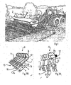
- Figure 1a shows an agricultural machine 2 in the form of a seed drill drawn by a tractor 4.
- a seed drill drawn by a tractor 4.
- levelling devices 6 comprising a plurality of lamellae 7.
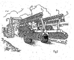
- Figure 2 shows another agricultural machine 2 in the form of a ring roller, which is folded up for road transport. At the top can be seen two rows of levelling devices 6, which in tillage form a single levelling device 6 at the extreme front in the direction of travel.
- FIG 3a shows a portion of the levelling device 6 with lamellae 7.
- Each of the lamellae 7 is manufactured from a flexible material, such as spring steel, and forms a curve 8.
- the lamella 7 is connected by means of screws 11 or similar to a bar 12 running across the direction of travel.
- the lamella 7 is formed into an elongated portion 13 and a soil tillage portion 14.
- the soil tillage portion 14 is according to this embodiment an angled, replaceable shearing plate, with one part of a fastening device 15 in the form of two parallel slits 16.
- Figure 3b shows lamellae 7, each of which has a soil tillage portion 14 in the form of an straight, replaceable shearing plate with parallel slits 16.
- Figures 4a and 4b show the angled shearing plate according to Figure 3a , with slits 16.
- the length of the slits is 45-50 mm, while the width of each slit is 7-11 mm and the distance between the slits is 9-13 mm. In a particular embodiment, the length of the slits is 47 mm, while the width of each slit is 9 mm and the distance between the slits is 11 mm.
- the shearing plate is also provided with a part of a fastening device in the form of holes 17 for connecting to the lamella 7.
- the fastening device also comprises a suitable fastening organ, such as a screw, arranged to penetrate the holes 17.
- Figures 5a and 5b show a further part of the said fastening device 15 in the form of a U-shaped fastening element 20 with shanks 22a, 22b adapted in size, shape and internal spacing to the openings 16 in Figures 3a-3c , and 4a and 4b , so that together they can form parts of the fastening device 15.
- the width of the shanks 22a, 22b is 43-48 mm, while their thickness is 5-9 mm and the distance between them is 9-13 mm.
- the width of the shanks is 45 mm, while their thickness is 7 mm and the distance between them is 11 mm.
- the shanks are conjoined by a portion 22c, the extension of which along the shanks is 65 mm, to provide a counterstay against the shearing plate 14.
- FIGS 5a-5b are shown as vertical (during use), parallel slits but could equally well be horizontal or have any conceivable orientation. They can be converging or diverging instead of parallel. They can be fewer or more than two and can have any conceivable shape, e.g. circular.
- the fastening element 20 is also provided with a third part of the fastening device 15 in the form of a pair of corresponding openings 22d for receiving a fourth part of the said fastening device in the form of a locking member 23 (see for example Figure 6b ).
- FIGS 6a and 6b show a tool 24 in the form of a pan breaking knife 26 fastened to the shearing plate 14 by means of the fastening element 20 and the locking member 23.
- the pan breaking knife 26 can be adjusted heightwise thanks to three openings 28, which can for example compensate for wear.
- the number of openings 28 can be fewer or more than three.
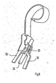
- FIGs 7a and 7b show an alternative pan breaking knife 26 with two shanks 30 mounted on the shearing plate on the lamella 7 to cultivate an existing soil pan at closer spacing.
- Figure 8 shows a further alternative pan breaking knife 26 with three shanks 30 mounted on the shearing plate on the lamella 7.
- Figures 9a and 9b show a further alternative pan breaking knife 26 with two flexible prongs 32.
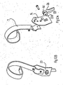
- Figures 10a and 10b show a further alternative pan breaking knife 26 with two rotatable discs 34, each provided with a rim 36.
- Figures 11a and 11b show a tool 24 in the form of a coulter entity 38 comprising a pair of seed or fertilizer coulters 40, with thereto arranged conduit 42, which are united in a tube 44, which transports granular material in the form of seed or fertilizer to the coulter entity 38.
- the coulter entity 38 is connected to the shearing plate 14 by means of the fastening element 20.
- the fastening device 15 i.e. the slits 16, the fastening element 20, the openings 22 and the pin 23, the tool 24 can be attached or detached rapidly. After detachment of the tool 24, the levelling device 6 is restored to its actual function without any subsequent attachment of lamellae or shearing plates being necessary.
- Figure 12a shows a tool 24 in the form of a pan breaking knife with welded on fastening element 20 in the form of parallel fastening members 46 with corresponding holes 22.
- Figure 12b shows how the pan breaking knife 26 has been connected to the shearing plate by the fastening member 46 being introduced into the slits 16 and by a pin 23 being introduced into the holes 22.
- any of the tools shown in Figures 7a-11b can be provided with fastening members 46 instead of using the separate fastening element 20 shown in Figures 5a-5b .
- Figures 13 a and 13 b show a shearing plate 14 with integral fastening member 50, which replaces the fastening element 20 shown in Figures 5a-5b .
- the locking member 23 has been described as a pin above, but may of course be any kind of fastening member.
- the tool has only been shown in combination with the shearing plate 14 (see Figure 3a ).
- the tool is also intended to be arranged together with the shearing plate 14 according to Figure 3b or the lamella according to Figure 3c .
- the soil tillage device has only been shown in the figures as a levelling device.
- the soil tillage device can instead be a harrow tine with integral or separate harrow tip, or a cultivator tine with integral or separate cultivator tip.
Abstract
Description
- The present invention relates to a soil tillage device, comprising a soil tillage portion. The present invention also refers to an agricultural machine with a similar soil tillage portion.
-
SE-C-510 727 - This levelling device is very effective when the soil is relatively easily cultivated, regardless of whether the soil is wet or dry, since the soil turned by the plough - the so-called furrow - can be levelled out with the levelling device. Difficulties can however arise if the soil has a high clay content, since this also means that the furrows become hard.
- If it rains heavily after sowing and the weather thereafter changes from wet to dry, which can mean that the surface dries rapidly, it happens on certain soil types, particularly those of a so-called silty nature, that a hard pan forms and the seed cannot force its way through this and therefore dies. To counteract this, one can use so-called pan breaking knife or other suitable tool to carefully break up the pan without damaging the seedlings.
- It happens that e.g. grass leys (green fodder) have to be harvested in the year after cereal has been harvested, whereby the ley is sown into the already sown crop. This practice is called undersowing and also occurs when leaching to lakes has to be prevented with a catch crop, e.g. grass or clover, through these taking up the soil nitrogen. In undersowing, the seed is usually placed on top of the soil surface so as not to damage the already sown crop with a tool.
-
GB-A-2176083 -
GB-A-2 333 220 - Other prior art soil tillage devices are disclosed by
DE-A-1 782 008 andFR-A-2 658 979 - The object of the present invention is to reduce the workload of the farmer in tool changes.
- This has been achieved by means of a soil tillage device according to Claim 1.
- It has also been achieved by an agricultural machine according to Claim 10.
- Hereby, the flexibility of the soil tillage device is increased, through the soil tillage device not having to be detached in order to attach the tool. This in turn means a time saving for the farmer.
- An elongated portion is included, which during use is angled away from the direction of tillage, wherein the soil tillage portion during its use extends across the direction of tillage. Hereby, a levelling of the soil is obtained.
- A curved portion and a connecting portion are suitably included, adapted to be fastened to an agricultural machine, wherein the curved portion extends between the elongated portion and the connecting portion. Furthermore, the connecting portion extends essentially in an opposing direction to that of the elongated portion. Hereby, flexibility properties are achieved in the device.
- The soil tillage portion forms a separate entity, which is detachably connected to the elongated portion by means of a fastening device. Hereby, a replaceable wearing part is achieved.
- The fastening device comprises a pair of parallel slits for receiving a U-shaped fastening element. Hereby, a stable connection for the tool is achieved.
- In a corresponding way, the tool has a connecting portion for receiving a fastening element and it is adapted to be fastened to a soil tillage device.
- The connecting portion preferably comprises at least one opening for receiving at least one fastening element. More particularly, the openings comprise a pair of parallel slits for receiving a U-shaped fastening element
- The length of the slits is 45-50 mm, while the width of each slit is 7-11 mm and the distance between the slits is 9-13 mm. Primarily, the length of the slits is 47 mm, while the width of each slit is 9 mm and the distance between the slits is 11 mm.
- The fastening device is advantageously arranged at the soil tillage portion.
- The tool adapted to be fastened to the soil tillage portion can be a elongated pan breaking member. Alternatively, the tool can be a disc-shaped pan breaking member.
- Alternatively, the tool can be a coulter entity, with at least one coulter and a tube for the supply of seed or fertilizer to the soil. By sowing with a coulter that scores a groove in the soil, e.g. in connection with undersowing, the germination rate of the seed is increased drastically. As a result of this, the amount of seed can be reduced and considerable cost savings made.
- In the following, the invention is described in more detail with reference to the attached drawings in which:
-
Figure 1 illustrates a tractor-drawn agricultural machine with a plurality of levelling devices; -
Figure 2 illustrates another agricultural machine with one levelling device; -
Figure 3a illustrates a levelling device with a plurality of lamellae arranged at an angled, replaceable shearing plate, with openings for receiving a fastening member; -
Figure 3b illustrates a levelling device with a plurality of lamellae arranged at a straight, replaceable shearing plate, with openings for receiving a fastening member; -
Figures 4a and 4b illustrate the shearing plate shown inFigure 3 a; -
Figures 5a and 5b illustrate a fastening member for interaction with the openings according toFigures 3a, 3b and4a and 4b ; -
Figures 6a and 6b show a pan breaking knife arranged at the shearing plate according toFigures 3a ,4a and 4b by means of the fastening member according toFigures 5a and 5b ; -
Figures 7a and 7b illustrate an alternative pan breaking knife arranged at the shearing plate according toFigures 3a ,4a and 4b by means of the fastening member according toFigures 5a and 5b ; -
Figure 8 illustrates an alternative pan breaking knife arranged at the shearing plate according toFigures 3a ,4a and 4b by means of the fastening member according toFigures 5a and 5b ; -
Figures 9a and 9b illustrate an alternative pan breaking knife arranged at the shearing plate according toFigures 3a ,4a and 4b by means of the fastening member according toFigures 5a and 5b ; -
Figures 10a and 10b illustrate an alternative pan breaking knife arranged at the shearing plate according toFigures 3a ,4a and 4b by means of the fastening member according toFigures 5a and 5b ; -
Figures 11a and 11b show a seed coulter arranged at the shearing plate according toFigures 3a ,4a and 4b by means of the fastening member according toFigures 5a and 5b ; -
Figures 12a and 12b illustrate a pan breaking knife with integral fastening member and arranged at the shearing plate according toFigures 3a ,4a and 4b : and -
Figures 13a and 13b illustrate a shearing plate with integral fastening member. -
Figure 1a shows an agricultural machine 2 in the form of a seed drill drawn by a tractor 4. In the front part of the seed drill are arranged - viewed in the direction of travel - one or morelevelling devices 6, comprising a plurality oflamellae 7. -
Figure 2 shows another agricultural machine 2 in the form of a ring roller, which is folded up for road transport. At the top can be seen two rows oflevelling devices 6, which in tillage form asingle levelling device 6 at the extreme front in the direction of travel. -
Figure 3a shows a portion of thelevelling device 6 withlamellae 7. Each of thelamellae 7 is manufactured from a flexible material, such as spring steel, and forms a curve 8. At the extremity of the curve 10, thelamella 7 is connected by means ofscrews 11 or similar to abar 12 running across the direction of travel. At the opposite extremity thelamella 7 is formed into anelongated portion 13 and asoil tillage portion 14. Thesoil tillage portion 14 is according to this embodiment an angled, replaceable shearing plate, with one part of afastening device 15 in the form of twoparallel slits 16. -
Figure 3b showslamellae 7, each of which has asoil tillage portion 14 in the form of an straight, replaceable shearing plate withparallel slits 16. -
Figures 4a and 4b show the angled shearing plate according toFigure 3a , withslits 16. The length of the slits is 45-50 mm, while the width of each slit is 7-11 mm and the distance between the slits is 9-13 mm. In a particular embodiment, the length of the slits is 47 mm, while the width of each slit is 9 mm and the distance between the slits is 11 mm. The shearing plate is also provided with a part of a fastening device in the form ofholes 17 for connecting to thelamella 7. The fastening device also comprises a suitable fastening organ, such as a screw, arranged to penetrate theholes 17. -
Figures 5a and 5b show a further part of the saidfastening device 15 in the form of aU-shaped fastening element 20 withshanks openings 16 inFigures 3a-3c , and4a and 4b , so that together they can form parts of thefastening device 15. In accordance with the dimensions of theslits 16 given above, the width of theshanks portion 22c, the extension of which along the shanks is 65 mm, to provide a counterstay against the shearingplate 14. - The openings in
Figures 5a-5b are shown as vertical (during use), parallel slits but could equally well be horizontal or have any conceivable orientation. They can be converging or diverging instead of parallel. They can be fewer or more than two and can have any conceivable shape, e.g. circular. - The
fastening element 20 is also provided with a third part of thefastening device 15 in the form of a pair of correspondingopenings 22d for receiving a fourth part of the said fastening device in the form of a locking member 23 (see for exampleFigure 6b ). -
Figures 6a and 6b show atool 24 in the form of apan breaking knife 26 fastened to theshearing plate 14 by means of thefastening element 20 and the lockingmember 23. Thepan breaking knife 26 can be adjusted heightwise thanks to threeopenings 28, which can for example compensate for wear. Of course, the number ofopenings 28 can be fewer or more than three. -
Figures 7a and 7b show an alternativepan breaking knife 26 with twoshanks 30 mounted on the shearing plate on thelamella 7 to cultivate an existing soil pan at closer spacing. -
Figure 8 shows a further alternativepan breaking knife 26 with threeshanks 30 mounted on the shearing plate on thelamella 7. -
Figures 9a and 9b show a further alternativepan breaking knife 26 with two flexible prongs 32. -
Figures 10a and 10b show a further alternativepan breaking knife 26 with tworotatable discs 34, each provided with arim 36. -
Figures 11a and 11b show atool 24 in the form of acoulter entity 38 comprising a pair of seed orfertilizer coulters 40, with thereto arrangedconduit 42, which are united in atube 44, which transports granular material in the form of seed or fertilizer to thecoulter entity 38. Thecoulter entity 38 is connected to theshearing plate 14 by means of thefastening element 20. - Thanks to the design of the
fastening device 15, i.e. theslits 16, thefastening element 20, the openings 22 and thepin 23, thetool 24 can be attached or detached rapidly. After detachment of thetool 24, thelevelling device 6 is restored to its actual function without any subsequent attachment of lamellae or shearing plates being necessary. -
Figure 12a shows atool 24 in the form of a pan breaking knife with welded onfastening element 20 in the form ofparallel fastening members 46 with corresponding holes 22. -
Figure 12b shows how thepan breaking knife 26 has been connected to the shearing plate by thefastening member 46 being introduced into theslits 16 and by apin 23 being introduced into the holes 22. - Of course any of the tools shown in
Figures 7a-11b can be provided withfastening members 46 instead of using theseparate fastening element 20 shown inFigures 5a-5b . -
Figures 13 a and 13 b show ashearing plate 14 withintegral fastening member 50, which replaces thefastening element 20 shown inFigures 5a-5b . - The locking
member 23 has been described as a pin above, but may of course be any kind of fastening member. - The tool has only been shown in combination with the shearing plate 14 (see
Figure 3a ). Of course, the tool is also intended to be arranged together with theshearing plate 14 according toFigure 3b or the lamella according toFigure 3c . - The soil tillage device has only been shown in the figures as a levelling device. Of course, the soil tillage device can instead be a harrow tine with integral or separate harrow tip, or a cultivator tine with integral or separate cultivator tip.
Claims (7)
- A soil tillage device, comprising at least one lamellae (7) having a soil tillage portion (14) in the end thereof, the soil tillage portion (14) of each lamellae (7) forms a separate entity, which is detachably connected to an elongated portion (13) of the lamellae by means of a connecting device (17), the soil tillage portion (14) is provided with a fastening device (15) for a tool (24) for soil tillage and/or spreading of granular material, characterised in that the fastening device (15) comprises a pair of parallel slits for receiving a U-shaped fastening element (20).
- A soil tillage device according to Claim 1, wherein said elongated portion (13), during use is angled away from the direction of tillage, wherein the soil tillage portion (14) during its use extends across the direction of tillage.
- A soil tillage device according to Claim 2, wherein each lamellae has a curved portion (8) and a connecting portion (10) adapted to be fastened to an agricultural machine, wherein the curved portion extends between the elongated portion (13) and the connecting portion (10).
- A soil tillage device according to Claim 3, wherein the connecting portion (10) extends essentially in an opposing direction to that of the elongated portion (13).
- A soil tillage device according to any one of claims 1-4, wherein the length of the slits is 45-50 mm, wherein the width of each slit is 7-11 mm and wherein the distance between the slits is 9-13 mm.
- A soil tillage device according to Claim 5, wherein the length of the slits is 47 mm and wherein the width of each slit is 9 mm and wherein the distance between the slits is 11 mm.
- An agricultural machine comprising a soil tillage device according to any of claims 1-6.
Applications Claiming Priority (3)
| Application Number | Priority Date | Filing Date | Title |
|---|---|---|---|
| SE0200984 | 2002-03-28 | ||
| SE0200984A SE521754C2 (en) | 2002-03-28 | 2002-03-28 | An tillage device and tools therefor and agricultural implements including an tillage device |
| PCT/SE2003/000430 WO2003081980A1 (en) | 2002-03-28 | 2003-03-14 | A soil tillage device |
Publications (3)
| Publication Number | Publication Date |
|---|---|
| EP1487249A1 EP1487249A1 (en) | 2004-12-22 |
| EP1487249B1 EP1487249B1 (en) | 2008-12-31 |
| EP1487249B2 true EP1487249B2 (en) | 2013-10-23 |
Family
ID=20287452
Family Applications (1)
| Application Number | Title | Priority Date | Filing Date |
|---|---|---|---|
| EP03745494.9A Expired - Lifetime EP1487249B2 (en) | 2002-03-28 | 2003-03-14 | A soil tillage device |
Country Status (6)
| Country | Link |
|---|---|
| EP (1) | EP1487249B2 (en) |
| AT (1) | ATE418852T1 (en) |
| AU (1) | AU2003216001A1 (en) |
| DE (1) | DE60325563D1 (en) |
| SE (1) | SE521754C2 (en) |
| WO (1) | WO2003081980A1 (en) |
Families Citing this family (8)
| Publication number | Priority date | Publication date | Assignee | Title |
|---|---|---|---|---|
| DE202007015639U1 (en) | 2007-11-09 | 2009-03-26 | Alois Pöttinger Maschinenfabrik Gmbh | agricultural machinery |
| DE202008004736U1 (en) | 2008-04-07 | 2009-08-20 | Alois Pöttinger Maschinenfabrik Gmbh | Harrow tine mold and / or storage |
| DE102010037032A1 (en) * | 2010-08-18 | 2012-02-23 | Amazonen-Werke H. Dreyer Gmbh & Co. Kg | Harrow device for tillage and / or sawing equipment |
| SE1250335A1 (en) * | 2012-04-03 | 2013-10-04 | Vaederstad Verken Ab | Agricultural implements, soil tillage procedures and additional tools for agricultural implements |
| DE202015105952U1 (en) * | 2015-11-06 | 2016-01-26 | Klaus Wallner | Attachment for harrow |
| DE102016118564A1 (en) * | 2016-09-30 | 2018-04-05 | Amazonen-Werke H. Dreyer Gmbh & Co. Kg | Agricultural machine |
| DE102017109371A1 (en) * | 2017-05-02 | 2018-11-08 | Klaus Wallner | Attachment for tines |
| CN110050547B (en) * | 2019-04-30 | 2021-04-13 | 徐州盛斗士生物科技有限公司 | Mango wrapped type shearing and screening front-entering type fertilization moving vehicle |
Citations (2)
| Publication number | Priority date | Publication date | Assignee | Title |
|---|---|---|---|---|
| GB2307389A (en) † | 1995-10-18 | 1997-05-28 | Vaederstad Verken Ab | Clod crusher |
| DE19836627A1 (en) † | 1998-08-13 | 2000-02-17 | Konrad Hendlmeier | Wing-shaped plough-share with detachable and adjustable extensions for more precise distribution of soil after ploughing |
Family Cites Families (7)
| Publication number | Priority date | Publication date | Assignee | Title |
|---|---|---|---|---|
| NL6710759A (en) * | 1967-08-04 | 1969-02-06 | ||
| DE8219144U1 (en) * | 1982-07-03 | 1982-10-07 | Schmotzer Agrartechnic GmbH, 8532 Bad Windsheim | TOW-EXTENDABLE PICK-UP ARRANGEMENTS |
| US4759301A (en) * | 1984-07-04 | 1988-07-26 | John David Thomas | Seed drill |
| FI852119L (en) * | 1985-05-28 | 1986-11-29 | Suomen Sokeri Oy | GOEDSLINGSBILL FOER EN SAODDGOEDSLINGSMASKIN. |
| FR2658979B1 (en) * | 1990-03-02 | 1992-08-07 | Sulky Burel Sa | TRACING DEVICE FOR AGRICULTURAL MACHINE. |
| FR2702627B1 (en) * | 1993-03-15 | 1995-05-05 | Terrenoire Manufacture Ressort | Flexible tine with interchangeable elements for tillage equipment. |
| GB2333220B (en) * | 1998-01-17 | 2002-06-05 | Jonathan Peter Rowe | Agricultural cultivator |
-
2002
- 2002-03-28 SE SE0200984A patent/SE521754C2/en not_active IP Right Cessation
-
2003
- 2003-03-14 AU AU2003216001A patent/AU2003216001A1/en not_active Abandoned
- 2003-03-14 WO PCT/SE2003/000430 patent/WO2003081980A1/en not_active Application Discontinuation
- 2003-03-14 AT AT03745494T patent/ATE418852T1/en not_active IP Right Cessation
- 2003-03-14 DE DE60325563T patent/DE60325563D1/en not_active Expired - Lifetime
- 2003-03-14 EP EP03745494.9A patent/EP1487249B2/en not_active Expired - Lifetime
Patent Citations (2)
| Publication number | Priority date | Publication date | Assignee | Title |
|---|---|---|---|---|
| GB2307389A (en) † | 1995-10-18 | 1997-05-28 | Vaederstad Verken Ab | Clod crusher |
| DE19836627A1 (en) † | 1998-08-13 | 2000-02-17 | Konrad Hendlmeier | Wing-shaped plough-share with detachable and adjustable extensions for more precise distribution of soil after ploughing |
Also Published As
| Publication number | Publication date |
|---|---|
| SE0200984L (en) | 2003-09-29 |
| EP1487249A1 (en) | 2004-12-22 |
| ATE418852T1 (en) | 2009-01-15 |
| SE521754C2 (en) | 2003-12-02 |
| AU2003216001A1 (en) | 2003-10-13 |
| WO2003081980A1 (en) | 2003-10-09 |
| SE0200984D0 (en) | 2002-03-28 |
| DE60325563D1 (en) | 2009-02-12 |
| EP1487249B1 (en) | 2008-12-31 |
Similar Documents
| Publication | Publication Date | Title |
|---|---|---|
| AU745874B2 (en) | Minimum till seeding knife | |
| US6178900B1 (en) | Combination chisel plow and fertilizer placement apparatus | |
| US10405473B2 (en) | Seed bed preparation and tillage apparatus | |
| US20180184569A1 (en) | A radial finger tillage disc applied to chain | |
| US6357368B1 (en) | Ground working paired row furrow opener | |
| AU2020102414B4 (en) | A seeding tool | |
| US10368474B2 (en) | Double rolling basket linkage | |
| US10681852B2 (en) | Hybrid tillage implement for vertical tillage and aeration of soil | |
| EP1487249B2 (en) | A soil tillage device | |
| US5862764A (en) | Method and apparatus for a floating frame field harrow | |
| US6345671B1 (en) | Flexible ground-driven residue management wheel | |
| Siemens et al. | Development and evaluation of a residue management wheel for hoe-type no-till drills | |
| CA2705616C (en) | Soil shaping agricultural implement | |
| US6293353B1 (en) | High mobility agricultural implement | |
| US10375874B2 (en) | Dual rate sweep load on field cultivator shank assembly | |
| US11558988B2 (en) | Rotary ground engaging tool with double loop barbed links | |
| US4142588A (en) | Lister stabilizer | |
| Nokes et al. | Stand, yield, weed biomass, and surface residue cover comparisons between three cropping/tillage systems on a well-drained silt loam soil in Ohio, USA | |
| US5005497A (en) | Deep banding knife with rod attachment | |
| US2739519A (en) | Tiller blade and standard | |
| US20130000931A1 (en) | Dual Blade Parallel Garden Hoe | |
| CZ27213U1 (en) | Inter-row cultivator working unit | |
| US11832539B2 (en) | Agricultural implement with open-ended rolling baskets | |
| CN2431704Y (en) | Universal cultivator for seeding | |
| CN208425151U (en) | A kind of new test field wheat rape cultivator |
Legal Events
| Date | Code | Title | Description |
|---|---|---|---|
| PUAI | Public reference made under article 153(3) epc to a published international application that has entered the european phase |
Free format text: ORIGINAL CODE: 0009012 |
|
| 17P | Request for examination filed |
Effective date: 20040914 |
|
| AK | Designated contracting states |
Kind code of ref document: A1 Designated state(s): AT BE BG CH CY CZ DE DK EE ES FI FR GB GR HU IE IT LI LU MC NL PT RO SE SI SK TR |
|
| AX | Request for extension of the european patent |
Extension state: AL LT LV MK |
|
| 17Q | First examination report despatched |
Effective date: 20060529 |
|
| GRAP | Despatch of communication of intention to grant a patent |
Free format text: ORIGINAL CODE: EPIDOSNIGR1 |
|
| RIC1 | Information provided on ipc code assigned before grant |
Ipc: A01B 25/00 20060101AFI20080620BHEP Ipc: A01B 49/06 20060101ALI20080620BHEP Ipc: A01C 5/06 20060101ALI20080620BHEP Ipc: A01B 23/02 20060101ALI20080620BHEP |
|
| GRAS | Grant fee paid |
Free format text: ORIGINAL CODE: EPIDOSNIGR3 |
|
| GRAA | (expected) grant |
Free format text: ORIGINAL CODE: 0009210 |
|
| AK | Designated contracting states |
Kind code of ref document: B1 Designated state(s): AT BE BG CH CY CZ DE DK EE ES FI FR GB GR HU IE IT LI LU MC NL PT RO SE SI SK TR |
|
| REG | Reference to a national code |
Ref country code: CH Ref legal event code: EP Ref country code: GB Ref legal event code: FG4D |
|
| REF | Corresponds to: |
Ref document number: 60325563 Country of ref document: DE Date of ref document: 20090212 Kind code of ref document: P |
|
| REG | Reference to a national code |
Ref country code: IE Ref legal event code: FG4D |
|
| PG25 | Lapsed in a contracting state [announced via postgrant information from national office to epo] |
Ref country code: FI Free format text: LAPSE BECAUSE OF FAILURE TO SUBMIT A TRANSLATION OF THE DESCRIPTION OR TO PAY THE FEE WITHIN THE PRESCRIBED TIME-LIMIT Effective date: 20081231 Ref country code: NL Free format text: LAPSE BECAUSE OF FAILURE TO SUBMIT A TRANSLATION OF THE DESCRIPTION OR TO PAY THE FEE WITHIN THE PRESCRIBED TIME-LIMIT Effective date: 20081231 Ref country code: SI Free format text: LAPSE BECAUSE OF FAILURE TO SUBMIT A TRANSLATION OF THE DESCRIPTION OR TO PAY THE FEE WITHIN THE PRESCRIBED TIME-LIMIT Effective date: 20081231 |
|
| NLV1 | Nl: lapsed or annulled due to failure to fulfill the requirements of art. 29p and 29m of the patents act | ||
| PG25 | Lapsed in a contracting state [announced via postgrant information from national office to epo] |
Ref country code: RO Free format text: LAPSE BECAUSE OF FAILURE TO SUBMIT A TRANSLATION OF THE DESCRIPTION OR TO PAY THE FEE WITHIN THE PRESCRIBED TIME-LIMIT Effective date: 20081231 Ref country code: ES Free format text: LAPSE BECAUSE OF FAILURE TO SUBMIT A TRANSLATION OF THE DESCRIPTION OR TO PAY THE FEE WITHIN THE PRESCRIBED TIME-LIMIT Effective date: 20090411 Ref country code: EE Free format text: LAPSE BECAUSE OF FAILURE TO SUBMIT A TRANSLATION OF THE DESCRIPTION OR TO PAY THE FEE WITHIN THE PRESCRIBED TIME-LIMIT Effective date: 20081231 Ref country code: BE Free format text: LAPSE BECAUSE OF FAILURE TO SUBMIT A TRANSLATION OF THE DESCRIPTION OR TO PAY THE FEE WITHIN THE PRESCRIBED TIME-LIMIT Effective date: 20081231 |
|
| PG25 | Lapsed in a contracting state [announced via postgrant information from national office to epo] |
Ref country code: PT Free format text: LAPSE BECAUSE OF FAILURE TO SUBMIT A TRANSLATION OF THE DESCRIPTION OR TO PAY THE FEE WITHIN THE PRESCRIBED TIME-LIMIT Effective date: 20090601 Ref country code: CZ Free format text: LAPSE BECAUSE OF FAILURE TO SUBMIT A TRANSLATION OF THE DESCRIPTION OR TO PAY THE FEE WITHIN THE PRESCRIBED TIME-LIMIT Effective date: 20081231 Ref country code: AT Free format text: LAPSE BECAUSE OF FAILURE TO SUBMIT A TRANSLATION OF THE DESCRIPTION OR TO PAY THE FEE WITHIN THE PRESCRIBED TIME-LIMIT Effective date: 20081231 Ref country code: SE Free format text: LAPSE BECAUSE OF FAILURE TO SUBMIT A TRANSLATION OF THE DESCRIPTION OR TO PAY THE FEE WITHIN THE PRESCRIBED TIME-LIMIT Effective date: 20090331 |
|
| PLBI | Opposition filed |
Free format text: ORIGINAL CODE: 0009260 |
|
| PG25 | Lapsed in a contracting state [announced via postgrant information from national office to epo] |
Ref country code: SK Free format text: LAPSE BECAUSE OF FAILURE TO SUBMIT A TRANSLATION OF THE DESCRIPTION OR TO PAY THE FEE WITHIN THE PRESCRIBED TIME-LIMIT Effective date: 20081231 |
|
| 26 | Opposition filed |
Opponent name: AMAZONEN-WERKE H. DREYER GMBH & CO. KG Effective date: 20090911 |
|
| PG25 | Lapsed in a contracting state [announced via postgrant information from national office to epo] |
Ref country code: DK Free format text: LAPSE BECAUSE OF FAILURE TO SUBMIT A TRANSLATION OF THE DESCRIPTION OR TO PAY THE FEE WITHIN THE PRESCRIBED TIME-LIMIT Effective date: 20081231 Ref country code: MC Free format text: LAPSE BECAUSE OF NON-PAYMENT OF DUE FEES Effective date: 20090331 |
|
| REG | Reference to a national code |
Ref country code: CH Ref legal event code: PL |
|
| PLAX | Notice of opposition and request to file observation + time limit sent |
Free format text: ORIGINAL CODE: EPIDOSNOBS2 |
|
| REG | Reference to a national code |
Ref country code: IE Ref legal event code: MM4A |
|
| PG25 | Lapsed in a contracting state [announced via postgrant information from national office to epo] |
Ref country code: IE Free format text: LAPSE BECAUSE OF NON-PAYMENT OF DUE FEES Effective date: 20090314 Ref country code: BG Free format text: LAPSE BECAUSE OF FAILURE TO SUBMIT A TRANSLATION OF THE DESCRIPTION OR TO PAY THE FEE WITHIN THE PRESCRIBED TIME-LIMIT Effective date: 20090331 Ref country code: CH Free format text: LAPSE BECAUSE OF NON-PAYMENT OF DUE FEES Effective date: 20090331 Ref country code: LI Free format text: LAPSE BECAUSE OF NON-PAYMENT OF DUE FEES Effective date: 20090331 |
|
| PLAF | Information modified related to communication of a notice of opposition and request to file observations + time limit |
Free format text: ORIGINAL CODE: EPIDOSCOBS2 |
|
| PLBB | Reply of patent proprietor to notice(s) of opposition received |
Free format text: ORIGINAL CODE: EPIDOSNOBS3 |
|
| PG25 | Lapsed in a contracting state [announced via postgrant information from national office to epo] |
Ref country code: GR Free format text: LAPSE BECAUSE OF FAILURE TO SUBMIT A TRANSLATION OF THE DESCRIPTION OR TO PAY THE FEE WITHIN THE PRESCRIBED TIME-LIMIT Effective date: 20090401 |
|
| PG25 | Lapsed in a contracting state [announced via postgrant information from national office to epo] |
Ref country code: IT Free format text: LAPSE BECAUSE OF FAILURE TO SUBMIT A TRANSLATION OF THE DESCRIPTION OR TO PAY THE FEE WITHIN THE PRESCRIBED TIME-LIMIT Effective date: 20081231 |
|
| PG25 | Lapsed in a contracting state [announced via postgrant information from national office to epo] |
Ref country code: LU Free format text: LAPSE BECAUSE OF NON-PAYMENT OF DUE FEES Effective date: 20090314 |
|
| PG25 | Lapsed in a contracting state [announced via postgrant information from national office to epo] |
Ref country code: HU Free format text: LAPSE BECAUSE OF FAILURE TO SUBMIT A TRANSLATION OF THE DESCRIPTION OR TO PAY THE FEE WITHIN THE PRESCRIBED TIME-LIMIT Effective date: 20090701 |
|
| PG25 | Lapsed in a contracting state [announced via postgrant information from national office to epo] |
Ref country code: TR Free format text: LAPSE BECAUSE OF FAILURE TO SUBMIT A TRANSLATION OF THE DESCRIPTION OR TO PAY THE FEE WITHIN THE PRESCRIBED TIME-LIMIT Effective date: 20081231 |
|
| PG25 | Lapsed in a contracting state [announced via postgrant information from national office to epo] |
Ref country code: CY Free format text: LAPSE BECAUSE OF FAILURE TO SUBMIT A TRANSLATION OF THE DESCRIPTION OR TO PAY THE FEE WITHIN THE PRESCRIBED TIME-LIMIT Effective date: 20081231 |
|
| PLAY | Examination report in opposition despatched + time limit |
Free format text: ORIGINAL CODE: EPIDOSNORE2 |
|
| PLAH | Information related to despatch of examination report in opposition + time limit modified |
Free format text: ORIGINAL CODE: EPIDOSCORE2 |
|
| PLAT | Information related to reply to examination report in opposition deleted |
Free format text: ORIGINAL CODE: EPIDOSDORE3 |
|
| PLBC | Reply to examination report in opposition received |
Free format text: ORIGINAL CODE: EPIDOSNORE3 |
|
| PLBC | Reply to examination report in opposition received |
Free format text: ORIGINAL CODE: EPIDOSNORE3 |
|
| PUAH | Patent maintained in amended form |
Free format text: ORIGINAL CODE: 0009272 |
|
| STAA | Information on the status of an ep patent application or granted ep patent |
Free format text: STATUS: PATENT MAINTAINED AS AMENDED |
|
| 27A | Patent maintained in amended form |
Effective date: 20131023 |
|
| AK | Designated contracting states |
Kind code of ref document: B2 Designated state(s): AT BE BG CH CY CZ DE DK EE ES FI FR GB GR HU IE IT LI LU MC NL PT RO SE SI SK TR |
|
| REG | Reference to a national code |
Ref country code: DE Ref legal event code: R102 Ref document number: 60325563 Country of ref document: DE Effective date: 20131023 |
|
| REG | Reference to a national code |
Ref country code: FR Ref legal event code: PLFP Year of fee payment: 13 |
|
| REG | Reference to a national code |
Ref country code: DE Ref legal event code: R081 Ref document number: 60325563 Country of ref document: DE Owner name: VAEDERSTAD HOLDING AB, SE Free format text: FORMER OWNER: VAEDERSTAD-VERKEN AB, VAEDERSTAD, SE |
|
| REG | Reference to a national code |
Ref country code: FR Ref legal event code: PLFP Year of fee payment: 14 |
|
| REG | Reference to a national code |
Ref country code: FR Ref legal event code: CA Effective date: 20160107 Ref country code: FR Ref legal event code: CD Owner name: VADERSTAD HOLDING AB, SE Effective date: 20160107 |
|
| REG | Reference to a national code |
Ref country code: FR Ref legal event code: PLFP Year of fee payment: 15 |
|
| REG | Reference to a national code |
Ref country code: FR Ref legal event code: PLFP Year of fee payment: 16 |
|
| PGFP | Annual fee paid to national office [announced via postgrant information from national office to epo] |
Ref country code: GB Payment date: 20180314 Year of fee payment: 16 Ref country code: DE Payment date: 20180227 Year of fee payment: 16 |
|
| PGFP | Annual fee paid to national office [announced via postgrant information from national office to epo] |
Ref country code: FR Payment date: 20180226 Year of fee payment: 16 |
|
| REG | Reference to a national code |
Ref country code: DE Ref legal event code: R119 Ref document number: 60325563 Country of ref document: DE |
|
| GBPC | Gb: european patent ceased through non-payment of renewal fee |
Effective date: 20190314 |
|
| PG25 | Lapsed in a contracting state [announced via postgrant information from national office to epo] |
Ref country code: DE Free format text: LAPSE BECAUSE OF NON-PAYMENT OF DUE FEES Effective date: 20191001 Ref country code: GB Free format text: LAPSE BECAUSE OF NON-PAYMENT OF DUE FEES Effective date: 20190314 |
|
| PG25 | Lapsed in a contracting state [announced via postgrant information from national office to epo] |
Ref country code: FR Free format text: LAPSE BECAUSE OF NON-PAYMENT OF DUE FEES Effective date: 20190331 |