DE102016118564A1 - Agricultural machine - Google Patents
Agricultural machine Download PDFInfo
- Publication number
- DE102016118564A1 DE102016118564A1 DE102016118564.7A DE102016118564A DE102016118564A1 DE 102016118564 A1 DE102016118564 A1 DE 102016118564A1 DE 102016118564 A DE102016118564 A DE 102016118564A DE 102016118564 A1 DE102016118564 A1 DE 102016118564A1
- Authority
- DE
- Germany
- Prior art keywords
- harrow
- tines
- ground
- harrow tines
- agricultural machine
- Prior art date
- Legal status (The legal status is an assumption and is not a legal conclusion. Google has not performed a legal analysis and makes no representation as to the accuracy of the status listed.)
- Withdrawn
Links
Images

Classifications
-
- A—HUMAN NECESSITIES
- A01—AGRICULTURE; FORESTRY; ANIMAL HUSBANDRY; HUNTING; TRAPPING; FISHING
- A01B—SOIL WORKING IN AGRICULTURE OR FORESTRY; PARTS, DETAILS, OR ACCESSORIES OF AGRICULTURAL MACHINES OR IMPLEMENTS, IN GENERAL
- A01B23/00—Elements, tools, or details of harrows
- A01B23/02—Teeth; Fixing the teeth
-
- A—HUMAN NECESSITIES
- A01—AGRICULTURE; FORESTRY; ANIMAL HUSBANDRY; HUNTING; TRAPPING; FISHING
- A01B—SOIL WORKING IN AGRICULTURE OR FORESTRY; PARTS, DETAILS, OR ACCESSORIES OF AGRICULTURAL MACHINES OR IMPLEMENTS, IN GENERAL
- A01B35/00—Other machines for working soil not specially adapted for working soil on which crops are growing
- A01B35/02—Other machines for working soil not specially adapted for working soil on which crops are growing with non-rotating tools
- A01B35/04—Other machines for working soil not specially adapted for working soil on which crops are growing with non-rotating tools drawn by animal or tractor or man-power
- A01B35/06—Other machines for working soil not specially adapted for working soil on which crops are growing with non-rotating tools drawn by animal or tractor or man-power with spring tools or with resiliently- or flexibly-attached rigid tools
-
- A—HUMAN NECESSITIES
- A01—AGRICULTURE; FORESTRY; ANIMAL HUSBANDRY; HUNTING; TRAPPING; FISHING
- A01C—PLANTING; SOWING; FERTILISING
- A01C5/00—Making or covering furrows or holes for sowing, planting or manuring
- A01C5/06—Machines for making or covering drills or furrows for sowing or planting
- A01C5/066—Devices for covering drills or furrows
Abstract
Landwirtschaftliche Maschine, insbesondere Sämaschine oder dergleichen, mit zumindest einem Scharstriegel, der mehrere beabstandet nebeneinander angeordnete Striegelemente (10.1, 10.2), die jeweils zumindest zwei über den Boden führbares und/oder in den Boden eingreifende und zueinander beabstandete Striegelzinken (10.3, 10.4) aufweisen, wobei das jeweilige Striegelement (10.1, 10.2) von einem sich von seiner Befestigungsstelle am Schar (1) oder einem sich quer zur Fahrtrichtung erstreckenden Querbalken gehalten ist, wobei die Striegelzinken auf der der Befestigungsstelle benachbarten Bereich durch zumindest einen Quersteg miteinander verbunden sind. Um ein vereinfachtes und verbessert ausgestaltetes Striegelelement (10.2), insbesondere für den Randbereich landwirtschaftlicher Maschinen, insbesondere Sämaschinen zu schaffen, ist vorgesehen, dass zumindest ein Striegelelement (10.2) drei beabstandet zueinander angeordnete Striegelzinken (10.3, 10.4) aufweist.Agricultural machine, in particular seed drill or the like, with at least one coulter harrow having a plurality of spaced next to each other Striegelemente (10.1, 10.2), each having at least two traversable over the ground and / or engaging in the ground and spaced harrow tines (10.3, 10.4) , wherein the respective Striegelement (10.1, 10.2) is held by a from its attachment point on the coulter (1) or extending transversely to the direction transverse bar, wherein the harrow tines are connected to each other on the attachment point by at least one crosspiece. In order to provide a simplified and improved harrow element (10.2), in particular for the edge region of agricultural machines, in particular seed drills, it is provided that at least one harrow element (10.2) has three harrow tines (10.3, 10.4) arranged at a distance from one another.
Description
Die Erfindung betrifft eine landwirtschaftliche Maschine gemäß des Oberbegriffes des Patentanspruches 1. The invention relates to an agricultural machine according to the preamble of claim 1.
Eine derartige landwirtschaftliche Maschine ist in
Auch sind landwirtschaftliche Maschinen bekannt, bei denen im Randbereich nur ein einzinkiges Striegelelement angeordnet ist. Hierfür muss dann jeweils auch für das einzinkige Striegelelement eine eigene Halterung zur Befestigung vorgesehen werden. Dieses aufwändig und teuer. Also agricultural machines are known in which only a one-armed harrow element is arranged in the edge region. For this purpose, a separate holder for mounting must then be provided in each case for the one-armed Striegelelement. This elaborate and expensive.
Der Erfindung liegt die Aufgabe zu Grunde, ein vereinfachtes und verbessert ausgestaltetes Striegelelement, insbesondere für den Randbereich landwirtschaftlicher Maschinen, insbesondere Sämaschinen zu schaffen. The object of the invention is to provide a simplified and improved harrow element, in particular for the edge region of agricultural machines, in particular seed drills.
Diese Aufgabe wird erfindungsgemäß dadurch gelöst, dass zumindest ein Striegelelement drei beabstandet zueinander angeordnete Striegelzinken aufweist. This object is achieved in that at least one harrow element has three spaced apart harrow tines.
Infolge dieser Maßnahme ergibt sich in einfacher Weise eine erhebliche Kosten- und Gewichtsreduzierung für die im Randbereich angeordneten Striegelelemente. Es werden hier im Hinblick auf bekannte Lösungen mit nebeneinander angeordneten einzinkigen und zweizinkingen Striegelelement ein erfindungsgemäßes dreizinkiges Striegelement geschaffen, welches drei Striegelzinken aufweist, es ergibt sich bildlich gesprochen ein „Dreizack“, As a result of this measure results in a simple manner, a significant cost and weight reduction for arranged in the edge region harrow elements. Here, with regard to known solutions with juxtaposed one-armed and two-pointed harrow element, an inventive three-pronged harrow element is created, which has three harrow tines, there is figuratively a "trident",
Eine einfache und kostengünstige sowie gewichtsoptimierte Ausgestaltung eines drei Striegelzinken aufweisenden Striegelelementes lässt sich in einfacher Weise dadurch schaffen, dass das Striegelelement mit drei beabstandet zueinander angeordneten Striegelzinken ein U-förmiges Grundstriegelelement mit zwei beabstandet angeordneten und mit ihren freien Enden in Richtung des Bodens weisenden Striegelzinken aufweist, dass zwischen diesen beiden beabstandet zueinander angeordneten Striegelzinken des Grundstriegelelementes zumindest annähernd mittig ein weiterer Striegelzinken als dritter Striegelzinken des Striegelelementes mittels Schraub- und/oder Klemmelementen angeordnet ist. A simple and inexpensive and weight-optimized design of a three harrow tines having harrow element can be created in a simple manner that the harrow element has three spaced apart harrow tines a U-shaped ground harrow element with two spaced arranged and pointing with their free ends in the direction of the ground harrow tines in that, between these two spaced-apart harrow tines of the ground harrow element, at least approximately in the middle, another harrow tines are arranged as third harrow tines of the harrow element by means of screwing and / or clamping elements.
Eine einfache Anordnung des zusätzlichen Striegelzinkens an einem zweizinkigen Striegelelement kann dadurch erreicht werden, dass der weitere Striegelzinken an seinem oberen Ende ein rechtwinklig abgebogenes winkelförmiges Befestigungselement aufweist, dass über das rechtwinklig abgebogene winkelförmige Befestigungselement mittels der Schraub- und/oder Klemmelementen der weitere Striegelzinken an dem Grundstriegelelement angeordnet ist. A simple arrangement of the additional harrow tine on a two-pronged harrow element can be achieved in that the further harrow tines at its upper end a right angle bent angle fastener that on the right angle bent angle fastener by means of screw and / or clamping elements of the harrow tines on the Basic harrow element is arranged.
Eine vorteilhafte Anordnung des Striegelelementes wird dadurch erreicht, dass an dem Querbalken des Scharstriegel oder dem jeweils äußeren und/oder im jeweils äußeren Bereich angeordneten Säschar jeweils als äußeres Striegelelement ein drei Striegelzinken aufweisendes Striegelelement angeordnet ist. An advantageous arrangement of the harrow element is achieved in that on the crossbar of the coulter harrow or the respective outer and / or arranged in the respective outer coulter in each case as an outer Harrow element a three harrow tines exhibiting harrow element is arranged.
Weitere Einzelheiten der Erfindung sind der Beispielsbeschreibung und den Zeichnungen zu entnehmen. Die Zeichnungen zeigen Further details of the invention can be taken from the example description and the drawings. The drawings show
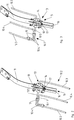
Das Säschar
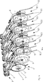
Die Striegelelemente
Die Striegelemente
Im Ausführungsbeispiel sind die als Randzinken ausgebildeten Striegelelemente
Das sogenannte Randstriegelelement
Der weitere Striegelzinken
In nicht dargestellter Weise können die Striegelelemente des Scharstriegels auch an einem am Rahmen der Maschine befestigten Querbalken angeordnet sein. In a manner not shown, the harrow elements of the coulter can also be arranged on a transom attached to the frame of the machine.
ZITATE ENTHALTEN IN DER BESCHREIBUNG QUOTES INCLUDE IN THE DESCRIPTION
Diese Liste der vom Anmelder aufgeführten Dokumente wurde automatisiert erzeugt und ist ausschließlich zur besseren Information des Lesers aufgenommen. Die Liste ist nicht Bestandteil der deutschen Patent- bzw. Gebrauchsmusteranmeldung. Das DPMA übernimmt keinerlei Haftung für etwaige Fehler oder Auslassungen.This list of the documents listed by the applicant has been generated automatically and is included solely for the better information of the reader. The list is not part of the German patent or utility model application. The DPMA assumes no liability for any errors or omissions.
Zitierte PatentliteraturCited patent literature
- DE 102008045635 A1 [0002] DE 102008045635 A1 [0002]
Claims (4)
Priority Applications (2)
| Application Number | Priority Date | Filing Date | Title |
|---|---|---|---|
| DE102016118564.7A DE102016118564A1 (en) | 2016-09-30 | 2016-09-30 | Agricultural machine |
| EP17401091.8A EP3300554A1 (en) | 2016-09-30 | 2017-08-24 | Agricultural machine |
Applications Claiming Priority (1)
| Application Number | Priority Date | Filing Date | Title |
|---|---|---|---|
| DE102016118564.7A DE102016118564A1 (en) | 2016-09-30 | 2016-09-30 | Agricultural machine |
Publications (1)
| Publication Number | Publication Date |
|---|---|
| DE102016118564A1 true DE102016118564A1 (en) | 2018-04-05 |
Family
ID=59859016
Family Applications (1)
| Application Number | Title | Priority Date | Filing Date |
|---|---|---|---|
| DE102016118564.7A Withdrawn DE102016118564A1 (en) | 2016-09-30 | 2016-09-30 | Agricultural machine |
Country Status (2)
| Country | Link |
|---|---|
| EP (1) | EP3300554A1 (en) |
| DE (1) | DE102016118564A1 (en) |
Citations (3)
| Publication number | Priority date | Publication date | Assignee | Title |
|---|---|---|---|---|
| DE102008045635A1 (en) | 2007-11-09 | 2009-05-28 | Alois Pöttinger Maschinenfabrik Gmbh | Agricultural machine e.g. sowing machine, for leveling ground for good seeds coverage, has shovel finger weeder retainer including angle adjusting device for adjusting inclination angle of tooth-shaped finger weeder element |
| AT506648B1 (en) * | 2008-04-07 | 2011-04-15 | Poettinger Ohg Alois | LOCKING DEVICE FOR GROUND AND FIELD PROCESSING EQUIPMENT |
| DE202010011146U1 (en) * | 2010-08-06 | 2011-11-23 | Paul Treffler | Harrow |
Family Cites Families (2)
| Publication number | Priority date | Publication date | Assignee | Title |
|---|---|---|---|---|
| AUPM761994A0 (en) * | 1994-08-23 | 1994-09-15 | Aurisch, Ellis John | Improved seeding implement assembly |
| SE521754C2 (en) * | 2002-03-28 | 2003-12-02 | Vaederstad Verken Ab | An tillage device and tools therefor and agricultural implements including an tillage device |
-
2016
- 2016-09-30 DE DE102016118564.7A patent/DE102016118564A1/en not_active Withdrawn
-
2017
- 2017-08-24 EP EP17401091.8A patent/EP3300554A1/en not_active Withdrawn
Patent Citations (3)
| Publication number | Priority date | Publication date | Assignee | Title |
|---|---|---|---|---|
| DE102008045635A1 (en) | 2007-11-09 | 2009-05-28 | Alois Pöttinger Maschinenfabrik Gmbh | Agricultural machine e.g. sowing machine, for leveling ground for good seeds coverage, has shovel finger weeder retainer including angle adjusting device for adjusting inclination angle of tooth-shaped finger weeder element |
| AT506648B1 (en) * | 2008-04-07 | 2011-04-15 | Poettinger Ohg Alois | LOCKING DEVICE FOR GROUND AND FIELD PROCESSING EQUIPMENT |
| DE202010011146U1 (en) * | 2010-08-06 | 2011-11-23 | Paul Treffler | Harrow |
Also Published As
| Publication number | Publication date |
|---|---|
| EP3300554A1 (en) | 2018-04-04 |
Similar Documents
| Publication | Publication Date | Title |
|---|---|---|
| EP2656708B1 (en) | Harrow | |
| DE102016106353A1 (en) | Device for fastening a tool to a frame | |
| EP3036982A1 (en) | Packer roller | |
| DE102014115209A1 (en) | Tillage tool | |
| EP3014965B1 (en) | Soil working tool | |
| EP2965603B1 (en) | Agricultural device | |
| DE102012111138A1 (en) | Tine e.g. grubber, for arrangement at frame of soil tilling machine, has fastening device for fastening wing blades at blade carrier and comprising screw, slot-shaped recess, hook-shaped projection, recesses and projections | |
| DE102012005027A1 (en) | Soil tilling machine e.g. coulter cultivator mounted on agricultural machine, has intermediate element that is arranged between other end region of S-shaped resilient spring tine and support frame element | |
| DE102008059144A1 (en) | Straw comb for being attached to three-point hitch of tractor for cultivation of soil, has shaft disks arranged parallel to each other and freely rotatable around axis that runs transverse to driving direction | |
| DE102016118564A1 (en) | Agricultural machine | |
| EP2420119B1 (en) | Spring tine furrow closer for soil-working and/or sowing device | |
| EP3172951B1 (en) | Soil working tool | |
| DE102008044520A1 (en) | Sowing device for use with agricultural tractor, has seeding coulter assigned to rotatably mounted deep guide wheel that is arranged adjacent to seed pressing roller such that outlines of roller and wheel partially intersect with each other | |
| EP2589282B1 (en) | Soil cultivation device with wing blade grubber tooth | |
| EP3085216A1 (en) | Agricultural machine | |
| DE202009000859U1 (en) | agricultural machinery | |
| DE1142248B (en) | Mouldboard of a plow | |
| AT525059B1 (en) | Harrows with spring-loaded tines for agriculture | |
| EP3398415A1 (en) | Attachment for tines | |
| EP2415336A1 (en) | Soil cultivation device | |
| DE102020117677B3 (en) | System for agricultural implements for tillage | |
| EP2572563A1 (en) | Spring-tooth harrow | |
| DE10307234B4 (en) | Device for tillage | |
| DE202010005461U1 (en) | Leaf spring element for soil tillage machines | |
| DE202017107892U1 (en) | Cultivator module for a tillage device |
Legal Events
| Date | Code | Title | Description |
|---|---|---|---|
| R079 | Amendment of ipc main class |
Free format text: PREVIOUS MAIN CLASS: A01C0005060000 Ipc: A01B0023020000 |
|
| R163 | Identified publications notified | ||
| R119 | Application deemed withdrawn, or ip right lapsed, due to non-payment of renewal fee |