EP1487186A1 - Redundanten Betrieb eines Endgerätes an zumindest zwei Kommunikationsknoten - Google Patents
Redundanten Betrieb eines Endgerätes an zumindest zwei Kommunikationsknoten Download PDFInfo
- Publication number
- EP1487186A1 EP1487186A1 EP03013173A EP03013173A EP1487186A1 EP 1487186 A1 EP1487186 A1 EP 1487186A1 EP 03013173 A EP03013173 A EP 03013173A EP 03013173 A EP03013173 A EP 03013173A EP 1487186 A1 EP1487186 A1 EP 1487186A1
- Authority
- EP
- European Patent Office
- Prior art keywords
- terminal
- communication
- communication node
- address
- node
- Prior art date
- Legal status (The legal status is an assumption and is not a legal conclusion. Google has not performed a legal analysis and makes no representation as to the accuracy of the status listed.)
- Granted
Links
- 238000004891 communication Methods 0.000 title claims abstract description 460
- 238000000034 method Methods 0.000 claims abstract description 27
- 230000005540 biological transmission Effects 0.000 claims description 8
- 238000012544 monitoring process Methods 0.000 claims description 5
- 238000012806 monitoring device Methods 0.000 claims description 3
- 230000006978 adaptation Effects 0.000 claims description 2
- 230000001419 dependent effect Effects 0.000 claims description 2
- 230000004044 response Effects 0.000 claims description 2
- 230000008859 change Effects 0.000 description 14
- 230000006870 function Effects 0.000 description 8
- 238000012546 transfer Methods 0.000 description 5
- 101100048435 Caenorhabditis elegans unc-18 gene Proteins 0.000 description 3
- 230000000712 assembly Effects 0.000 description 3
- 238000000429 assembly Methods 0.000 description 3
- 238000013475 authorization Methods 0.000 description 3
- 230000000977 initiatory effect Effects 0.000 description 2
- 230000007257 malfunction Effects 0.000 description 2
- 230000015556 catabolic process Effects 0.000 description 1
- 238000006243 chemical reaction Methods 0.000 description 1
- 238000012790 confirmation Methods 0.000 description 1
- 125000004122 cyclic group Chemical class 0.000 description 1
- 230000007423 decrease Effects 0.000 description 1
- 238000006731 degradation reaction Methods 0.000 description 1
- 238000005516 engineering process Methods 0.000 description 1
- 230000008569 process Effects 0.000 description 1
- 230000009467 reduction Effects 0.000 description 1
- 230000011664 signaling Effects 0.000 description 1
- 238000012360 testing method Methods 0.000 description 1
Images

Classifications
-
- H—ELECTRICITY
- H04—ELECTRIC COMMUNICATION TECHNIQUE
- H04M—TELEPHONIC COMMUNICATION
- H04M7/00—Arrangements for interconnection between switching centres
- H04M7/006—Networks other than PSTN/ISDN providing telephone service, e.g. Voice over Internet Protocol (VoIP), including next generation networks with a packet-switched transport layer
-
- H—ELECTRICITY
- H04—ELECTRIC COMMUNICATION TECHNIQUE
- H04M—TELEPHONIC COMMUNICATION
- H04M3/00—Automatic or semi-automatic exchanges
- H04M3/42—Systems providing special services or facilities to subscribers
- H04M3/42314—Systems providing special services or facilities to subscribers in private branch exchanges
- H04M3/42323—PBX's with CTI arrangements
Definitions
- the invention relates to a method for alternating operation a terminal to at least two communication nodes and a communication arrangement for carrying out the method.
- each terminal In communication networks are usually a variety of Terminals and multiple communication nodes arranged.
- circuit-switched communication arrangements for example in ISDN systems, each terminal is in each case at one Communication node (switching device) permanently logged and thus assigned to this. This assignment is thereby given by the wiring, so that a terminal, For example, a telephone or a fax machine, exactly is notified of that switching device with which This terminal is also physically connected.
- voice data networks are one of the communication nodes in the respective Speech data network permanently assigned and logged in to this.
- H.323 ITU-T-H.323
- SIP Session Initiation Protocol
- a voice data network can - unlike the circuit-switched Communication networks - in principle any network component, So each terminal and each communication node, with every other network component directly data (in particular Exchange voice data).
- a fixed assignment of the network components to each other, as in the circuit-switched Communication networks given due to the wiring is not mandatory or desirable in voice data networks.
- the terminals in voice data networks are often referred to as “Clients", because these devices are significant different from circuit-switched terminals. So can For example, as a phone with network connection or also as a computer with a communication software installed on it be designed.
- the communication nodes in the voice data networks are often called “gatekeepers” (H.323) or “Proxy” or “SIP Proxy” (SIP protocol), since the function of these communication nodes next the connection initiation between the clients also the access control to transmission facilities to other networks, the so-called gateways.
- the following is for simplicity for gatekeeper and (SIP) proxy uniform the Term "gatekeeper" used.
- the communication nodes of the voice data networks are configuration data stored on those terminals that are on logged in to this communication node. That's for example Information about the permissions of each Clients or the user of the respective client, affiliations to call pickup groups, the phone number of Clients etc ..
- the communication node (gatekeeper) to which A client logged in is also called a “home node” or Called “Home Gatekeeper”. Should this client be on a other communication nodes are operated, the corresponding Terminal (client) logged off at the home node and at another communication node, with only a temporary one Change also called “adoptive gatekeeper", registered.
- the terminal can be transferred to the adoptive gatekeeper operated in the same way as at its home node. If this "move” to the adoptive gatekeeper not only temporarily (temporarily), but permanently, will the adoptive gatekeeper now to the new home node for the terminal.
- the object of the invention is to propose a method with the change of terminals between two communication nodes with little or no manual effort feasible, and propose a communication arrangement, in the change of terminals between communication nodes with as little manual effort as possible.
- the object is for the method by the features of the claim 1 and for the arrangement by the features of Patent claim 15 solved.
- the solution provides for the procedure that the reachability the first communication node is monitored that in the case of unavailability of the first communication node a Status information about unavailability is generated and that, due to the status information, a logical connection between the terminal and the second communication node is established and the operation of the terminal automatically at the second communication node, which is a second address is assigned takes place. This will ensure that in the case of unavailability of the home communication node of the Terminal this device in the shortest possible time again is operational without requiring manual input are.
- the solution provides for the communication arrangement that in the communication network arranged a management server is that in the management server a copy of the necessary Configuration data is stored in the communication network a monitoring device is present, monitoring the accessibility of the first communication node, that means are provided for transmitting the copy the necessary configuration data to a second communication node in case of unavailability of the first Communication node, so that the operation of the terminal at Inaccessibility of the first communication node on the second communication node takes place.
- the method is characterized by the characterizing features of the dependent Claims 2 to 13 advantageously designed.
- the advantages described for the method apply mutatis mutandis, for the arrangement.
- That from the first communication node to the second communication node changed terminal can with its full Functionality continues to operate when in the first Communication node terminal concerning the operation of the Terminal necessary configuration data are stored, and if the necessary configuration data for the operation of the Terminal at a second communication node to the second Communication nodes are transferred out.
- the necessary configuration data for the operation of the Terminal at a second communication node to the second Communication nodes are transferred out.
- Transmitter-specific configuration data transmitted can also be called "comfort features" of the affected terminal continue to be used.
- the configuration data for a terminal also goes to one Total failure of the first communication node is not lost if stored in the terminal a copy of the configuration data will, and if after the login of the terminal at the second communication node, the copy of the configuration data from the terminal to the second communication node is transmitted and from the second communication node to Operation of the terminal is used. In this storage the configuration data in the terminal itself is unnecessary.
- the operation of a central database for configuration data in the communication network With omission a central database can also be linked to a (central) Management server be waived.
- the terminal can in the case of unavailability of the first communication node without further inquiry at another instance and thus without delay to a second communication node change by storing the second address in the terminal and the terminal turns itself off when unreachable of the first communication node based on the stored second address at the second communication node logs.
- a communication network with many communication nodes increases the probability of successful login at an adoptive communication node
- further communication nodes with one each own address are arranged, wherein in the terminal a sorted list of the addresses of the communication nodes is stored, and wherein unavailability of the first communication node the list of communication nodes worked as long by sign-on attempts of the terminal until an application is made to one of the communication nodes is done.
- the list will be optimized for performance the communication node is sorted in the way that a login attempt at a very powerful first Communication node takes place in case of unavailability this second communication node at the expense of Performance degradation logging in with less powerful To try communication nodes.
- the storage of configuration data or their copy in The terminal can be avoided by entering the management server a copy of the configuration data is stored and after upon log-on of the terminal at the second communication node the copy of the configuration data from the Transfer management server to the second communication node and from the second communication node to the operation of the terminal is used.
- the configuration of a new communication node address in the terminal can at the change of the communication node be avoided if in the communication network, a management server is operated, in which a copy of the configuration data and the first address is stored, where from the management server, the reachability of the first communication node is monitored, and where by the management server in the case of unavailability of the first communication node the copy of the configuration data and the stored ones transmit first address to the second communication node becomes.
- the second communication node assigned the first address, and from the second communication node is based on the received copy of the configuration data for the terminal by assigning the first address the function of the first communication node exercised.
- the programming of the terminal is in this procedure not affected by the change of the communication node.
- communication nodes can be different Type used to operate the terminal.
- a change of the communication node without influence on the Terminal is particularly easy to accomplish when as the communication nodes each communication modules of a modular communication system can be used if as a management server, a control board of the modular communication system is used, and if after commissioning of the communication modules respectively the transmission of the configuration data and the respective Address from the control board to the respective one Communication module takes place.
- the original state of the communication network is automatically restored by the operation of the terminal at the second communication node the unavailability the first communication node is monitored, and by the terminal is logged off at the second communication node and logged back in to the first communication node becomes after the first communication node again is reachable.
- a separate monitoring entity in the communication network can be omitted if monitoring by the second Communication node or by the terminal itself.
- Fig. 1 is a first embodiment, a communication network shown, which consists of a data line LAN1, two communication nodes GK1, GK2 and a terminal EG1 consists.
- the communication network shown are still more Arranged communication nodes and terminals; in the Figure 1, however, are only to illustrate the embodiment required network components shown.
- Both Communication nodes GK1, GK2 are gatekeepers in a VoIP communication arrangement, and at the terminal EG1 is a voice data terminal, ie one VoIP client.
- the communication nodes GK1, GK2 and the Terminal EG1 exchange data, in particular voice data the data line LAN1 together.
- the data line LAN1 is part of a packet-switched network in which the data be exchanged according to the internet protocol.
- the communication node GK1 is a first Address
- the communication node GK2 a second address
- the terminal EG1 assigned a terminal address.
- the terminal EG1 is operated at the communication node GK1, It is thus logged on to the communication node GK1.
- configuration data are stored, which concern the terminal EG1.
- To this configuration data include, for example, information about the authorization the terminal EG1 to make external telephone calls, Information about group affiliations and other information.
- These configuration data are in the communication node GK1 summarized to a configuration data set, from which a current copy is made at regular intervals which copy is in each case to the terminal EG1 is transmitted. In a separate memory area of the Terminal EG1 will save this copy. If a newly created copy not from the previously created and transferred Copy is different, the retransmission is omitted the configuration data to the terminal.
- Also stored in the terminal EG1 is a list of all Communication node GK1, GK2 of the communication network, which can be used by the terminal EG1.
- These List is prioritized, that is, in the first place of the list the communication node GK1, which acts as a home node, ranked second in the best-suited Replacement communication node provided communication node GK2 and at the other parts of the list others, in the figure 1 not shown communication node of the communication network.
- the configuration data can be between necessary configuration data and complete configuration data become.
- Necessary configuration data are those Configuration data that is mandatory for doing so a terminal at a communication node with a basic functionality, So to exercise a pure telephony function, can be operated.
- Complete configuration data also include such settings and information, that for the realization of so-called comfort features are required, for example for the Configuration of call pickup groups, personal phone directories etc.
- the complete configuration data as a copy in the Terminal EG1 stored.
- the terminal EG1 checks at regular intervals, whether the communication node GK1 is reachable. That's it Terminal EG1 equipped with a monitoring device. If in the communication node GK1 or in the connection between the terminal EG1 and the communication node GK1 If an error occurs, the terminal EG1 makes the error "Unavailability" fixed. In the terminal EG1 is a the Error case generates corresponding status information, and the Login function of the terminal EG1 attempts as a result of this Status information, located at another communication node of the communication network. This calls that Terminal EG1 stored in it list of available communication nodes and reads the network address from this list the prioritized replacement system, namely the communication node GK2, out.
- the terminal EG1 now transmits the communication node GK2 a notification message.
- the communication node GK2 notes that he has sufficient Has spare capacity and that the terminal EG2 is entitled to do so is to log in to the communication node GK2.
- the communication node GK2 sends a confirmation message to the terminal EG1, which in response to the stored as a copy configuration data to the communication node GK2 shipped.
- To this transmission of the configuration data includes the terminal EG1 as a transmission means a program with appropriately trained communication subroutines.
- the communication node GK2 configured based on the received configuration data related to the terminal EG1 in the same way as before the communication node GK1 was configured.
- the communication node GK2 now checks in turn in regular Time intervals, whether the communication node GK1, whose terminal EG1 he manages as a "guest", again operational is, or whether the connection to this communication node GK1 exists again. Once this is the case, withdraws the communication node GK2 the terminal EG1 authorization to use the communication node GK2, what the logout of the terminal EG1 at the communication node GK2 equivalent. As a result, the terminal EG1 is due the regular checks, whether the communication node used GK2 is reachable, again the error case of the Inaccessibility and starts again based on the stored, sorted (prioritized) list, a usable one To find communication nodes. Because the list entry with the highest priority, the entry of the communication node GK1 is, in turn, a registration of the terminal EG1 at the communication node GK1, whereby the original Condition is restored.
- the terminal EG1 itself in regular Check intervals whether the communication node GK1 or restored the connection to this communication node GK1 is, and after the restoration of the replacement Log off used communication node GK2 and log in to the communication node GK1 again.
- the original state can be the components of the communication network also be programmed so that a change of Terminal EG1 from the communication node GK2 back to the Communication node GK1 is no longer done, but that the Communication node GK2 now the home communication node of the terminal EG1 and the original Home communication node GK1 now to a corresponding prioritized replacement communication node.
- FIG 2 is as a second embodiment, a communication network shown which the communication network from Figure 1 is similar and which also with a data line LAN2 is equipped. Via the data line LAN2 are the terminal EG2, the communication nodes GK3, GK4 and the management server VS connected to each other. Analogous to the embodiment of Figure 1 are the components of shown here communication network respectively network addresses assigned.
- the terminal EG2 is operated at the communication node GK3.
- the communication node GK4 is intended by the terminal EG2 be used in such cases where the communication node GK3 is not reachable due to a fault.
- In the terminal EG2 is the network address of the management server VS saved.
- the communication node GK4 is a so-called "passive system" arranged in the communication network. It means that in the case of trouble the communication node GK4 of none Terminal of the communication network is used, but this is kept only as a replacement system.
- the communication network can be next to the active communication node GK3 a larger number of other active communication nodes and also other passive communication nodes be arranged; the set of all passive communication nodes is also referred to as a "backup pool".
- the management server located in the communication network VS includes a database containing the configuration data all active communication node GK3 of the communication network are stored in a copy. This takes place in regular Time intervals a data comparison between the active Communication node and the management server VS instead.
- the management server VS now checks whether the communication node GK3 actually unreachable is, and if so, determines a replacement communication node, in the present embodiment, the communication node GK4.
- the management server VS now transfers to the Communication node GK4 stored in its database Configuration data of communication node GK3. Based This configuration data configures the configuration node GK4 in the same way as before the communication node GK3 was configured, and will be following to an active communication node.
- By sending a Test message to the communication node GK4 provides the management server VS firm readiness and transmitted to the terminal EG2 the network address of the communication node GK4.
- the terminal EG2 now registers the communication node GK4 as its assigned home communication node and logs in to this communication node GK4 on.
- the communication node GK4 If the communication node GK4 identical or even a better performance than the communication node GK3 offers, the communication node GK4 also stays behind Restoration of the accessibility of the communication node GK3 active communication node while the now restored Communication node GK3 to a passive, So it becomes a replacement communication node. If the However, communication node GK4 has a lower performance when the communication node GK3 has, is with the Change of the terminal EG2 from the communication node GK3 to the communication node GK4 down a function reduction occurred.
- the management server initiates VS after restoration of the reachability of the communication node GK3 that the stored in the management server VS Configuration data of communication node GK3 turn to this recovered communication node GK3 and this is its original function resumes.
- the management server VS this configuration data also to another replacement communication node with the corresponding scope of the Communicate communication network to the functionality of the terminal EG2 again to ensure full extent.
- the management server VS further comprises an adaptation unit, convert the configuration data in their format can. This is necessary because different in communication nodes Type the configuration data also in different Way are stored. If now in copy stored configuration data with a communication node is to be used by another type Management server VS a corresponding reconfiguration of the Configuration data made.
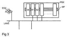
- FIG 3 is a third embodiment, a communication network shown with a data line LAN3 at the the terminal EG3 and the communication system PBX connected are.
- the PBX communication system is a modular communication system in which different Assemblies SB, B1, B2 via a base plate BP (Backplane) connected to an electrical data bus are.
- BP Backplane
- the communication modules B1, B2 are used as a communication node for the terminal EG3 and others Terminals (not shown here) in the communication network.
- the communication modules B1, B2 are each on the data line LAN3 connected.
- voice data communication modules B1, B2 are in the communication PBX even more, not shown here Assemblies for connecting circuit-switched terminals and those for access to circuit-switched communication networks, So gateway modules, plugged.
- the terminal EG3 is, together with others, not shown here Terminals logged on the communication board B1. For registration and for ongoing operation is in the terminal EG3, the network address of the communication module B1 saved.
- the communication module B2 is located is in passive operation and is in the communication system PBX as a replacement module for the active communication module B1 and other active communication modules not shown here maintained.
- the control module SB controls the communication modules B1, B2.
- When one of the communication boards B1, B2 starts (“booted") will be from the control board SB to the respective communication module B1, B2 first transmit the required operating software. With This operating software becomes the communication modules B1, B2 started.
- the control board transfers to the respective communication module B1, B2 the Configuration data representing the terminals, each by the Communication module B1, B2 are concerned relate.
- the respective communication module B1, B2 from the control board SB by assignment of the respective Network address of the communication module B1, B2 activated. The just described procedure is also called "loading" the Module called.
- Communication network will initially only the Communication module B1 with operating software, configuration data and a network address.
- the communication module B2 initially remains passive (inactive). Because in the terminal EG3 assigned to the communication board B1 Network address is stored, the terminal EG3 log in to this communication board B1. With the Registration and the establishment of the terminal EG3 are in the communication module B1 configuration data created or changed at regular intervals in copy in be saved to a memory of the control board.
- the control module SB monitors at regular intervals the communication board B1 and asks to regularly from this communication module B1 a status message from.
- the communication module B1 in turn checks regularly, whether their connection to the LAN3 and data line to the terminals registered with her, in this case the exemplarily considered terminal EG3 exists.
- control board Now still a connection to the communication module B1, it switches the communication board B1 in the Operating state "inactive". If no connection to the Communication board B1 is the control board goes anyway from an inactive operating state of the communication module B1 off. In both cases, the control module generates an internal status information about the Inaccessibility or malfunction and now loads the communication module B2 with operating software and the configuration data, originally from the communications board B1 were saved as a copy. Finally, the control assembly points SB of the communication module B2 that Network address too, originally from the communications board B1 was used, thereby switching the communication module B2 in the active operating state. The terminal EG3 now uses, without him in another network address for the communication module to be used had to be stored, the communication module B2. No change in the scope of services has occurred.
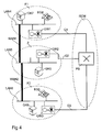
- the fourth exemplary embodiment is a distributed example Communication network with a central location Z and two branch sites F1, F2 shown, as it is, for example for banks or insurance companies with a central office and several branches.
- branch locations F1, F2 the data networks LAN4, LAN6 operated, and in the central location Z is the data network LAN5 operated.
- the branch site F1 are at the Data network LAN4, the terminal EG4, the communication node GK7, which is designed as a gatekeeper, and the gateway GW1 connected.
- Via gateway GW1 is the branch location F1 to the public switched communication network ISDN connected.
- the terminal EG5 the communication node GK6 (also trained as gatekeeper) and the gateway GW3 is connected, the latter via the communication line Q3 with the communication network ISDN connected is.
- the central location Z is with equipped the data network LAN5, wherein on the data network LAN5 the communication node GK5 and the gateway GW2 connected are, the gateway GW2 via the communication line Q2 connected to the public communication network ISDN is.
- the data networks LAN4 and LAN5 are over the Wide area data line WAN1 interconnected, and the Data network LAN6 is connected to the data network LAN5 via the long-distance data line WAN2 connected.
- the public communication network has at least one network node PS ("public switch"), with which the communication lines Q1, Q2, Q3 and (not shown here) external subscriber lines can be linked.
- the gateways GW1, GW2, GW3 are each the link of the data network LAN4, LAN5, LAN6 to the public Communication network ISDN. These gateways are controlled GW1, GW2, GW3 from the respective communication node (Gatekeeper) GK7, GK5, GK6 in the respective data network LAN4, LAN5, LAN6.
- GK7, GK5, GK6 in the respective data network LAN4, LAN5, LAN6 In normal (trouble-free) operation of the represented communication network are all communication links between the locations F1, F2, Z under Use of the WAN1 and WAN2 long-distance data transmission lines. Connections with external participants, ie with participants, who use the public communications network ISDN, are exclusively via the communication line Q2 and the gateway GW2.
- the terminals EG4, EG5 are at the communication node GK5 logged, in which also these terminals EG4, EG5 assigned Configuration data are stored. So if from the terminal EG4 or the terminal EG5 with an external Participant is communicated, then this call connection in the case of the terminal EG4 via the data network LAN4, then over the wide-area data line WAN1, then over the Data network LAN5 and finally via the gateway GW2 and the Communication line Q2 to the subscriber of the communication network ISDN guided.
- Analog will be discussions between the terminal EG5 and an external subscriber using of the data network LAN6, the long-distance data transmission line WAN2 the data network LAN5, the gateway GW2, the communication line Q2 and finally on the - not shown here - Calling centers of the public Communication network ISDN.
- the gateway GW1 and the used for controlling the gateway GW1 communication node GK7 neither for external connections nor for the connections used to the central location Z.
- the network components Gateway GW3 and communication node GK6 in trouble-free operation of the network is not used.
- the terminals EG4, EG5 associated configuration data are, as already mentioned, stored in the communication node GK5.
- a copy the configuration data concerning the terminal EG4 are stored in the communication node GK7.
- the communication node GK7 is so preprogrammed that the terminal EG4 instead of at the communication node GK5 at the Communication node GK7 can be operated.
- the communication node GK7 as an emergency system with a lower performance and with a lower performance than the communication node GK5 is its configuration regarding of the terminal EG4 of course limited.
- the network address of the communication node GK5 stored.
- the network address of Communication node GK7 stored.
- One in the terminal EG4 installed monitoring function checks in regular Time intervals, whether the communication node GK5 achievable is. If this accessibility no longer exists is, for example, due to a failure of the long-distance data line WAN1 or due to a failure of the communication node GK5, in the terminal EG4 a corresponding Status information generated and it logs in to the communication node GK7 on.
- the communication node GK7 is such programmed that all connections of the terminal EG4, the so far over the wide-area data line WAN1 and the Communication node GK5 were now under use of the gateway GW1 and the communication line Q1 via the public communication network ISDN be performed. This is despite the unavailability of the communication node GK5 the terminal EG4 continues to be used. In analog Way is also the terminal EG5 for replacement use of the communication node GK6 and the gateway GW3 instead the wide area data line WAN3 and the central communication node GK5 programmed.
- the now used substitute communication node GK7 checks at regular intervals whether the communication node GK5 is accessible again. As soon as that happens is, the communication node GK7 deprives the terminal EG4 the authorization to use it. As a result, that starts Terminal EG4 a renewed logon attempt, again in the Order that first log in to the communication node GK5 and only then a login attempt at the communication node GK7 is started. But there the communication node GK5 is reachable again, the first logon attempt lead to success, leaving the original configuration the communication network is restored.
- the terminal EG4 itself in regular Check intervals whether the communication node GK5 again is achievable, and - if so - of the used Log off communication node GK7 and at the communication node Login GK5 again.
- Upcoming communication connections (calls) for the terminal EG4 from a participant of the public communication network ISDN are from the public network node PS via the communication line Q1 to the gateway GW1.
- the gateway GW "translates" the call under control the communication node GK7 as a gatekeeper in the data network LAN4.
- the conversation is made via the long-distance data line WAN1 to the data network LAN5 and thus into the "responsibility" of the communication node GK5.
- the terminal EG4 logged in, so the Talk now at this terminal EG4, again via the data networks LAN5, LAN4 and the wide area data line WAN1, is signaled.
Landscapes
- Engineering & Computer Science (AREA)
- Signal Processing (AREA)
- Computer Networks & Wireless Communication (AREA)
- Data Exchanges In Wide-Area Networks (AREA)
- Small-Scale Networks (AREA)
Abstract
Description
- Figur 1
- ein Kommunikationsnetzwerk mit einer Datenleitung, einem Endgerät und zwei Kommunikationsknoten,
- Figur 2
- ein Datennetz mit einer Datenleitung, einem Endgerät, zwei Kommunikationsknoten und einem Verwaltungs-Server,
- Figur 3
- ein Kommunikationsnetzwerk mit einer Datenleitung, einem Endgerät und einer modular aufgebauten Kommunikationsanlage mit zwei Kommunikationsbaugruppen und einer Steuerungsbaugruppe, und
- Figur 4
- ein verteiltes Kommunikationsnetzwerk mit einer Zentrale, zwei Filialen, einem Datennetz, einem leitungsvermittelten Netzwerk, zwei Endgeräten und drei Kommunikationsknoten.
Claims (16)
- Verfahren zum wechselweisen Betrieb eines Endgerätes (EG1; EG2; EG3; EG4) an zumindest zwei Kommunikationsknoten (GK1, GK2; GK3, GK4; B1, B2; GK5, GK6),
wobei die Kommunikationsknoten und das Endgerät (EG1; EG2; EG3; EG4) in einem Kommunikationsnetzwerk angeordnet sind,
wobei zum Betrieb des Endgerätes (EG1; EG2; EG3; EG4) an einem ersten der Kommunikationsknoten (GK1; GK3; B1; GK5) mit einer ersten Adresse zwischen dem Endgerät (EG1; EG2; EG3; EG4) und diesem ersten Kommunikationsknoten (GK1; GK3; B1; GK5) angemeldet wird,
wobei nach der Anmeldung eine logische Verbindung zwischen dem Endgerät (EG1; EG2; EG3; EG4) und dem ersten Kommunikationsknoten (GK1; GK3; B1; GK5) besteht, und
wobei die erste Adresse in dem Endgerät (EG1; EG2; EG3; EG4) zur Anmeldung gespeichert ist,
dadurch gekennzeichnet, dass die Erreichbarkeit des ersten Kommunikationsknotens (GK1; GK3; B1; GK5) überwacht wird,
dass bei Nichterreichbarkeit des ersten Kommunikationsknotens (GK1; GK3; B1; GK5) eine Statusinformation über die Nichterreichbarkeit erzeugt wird,
dass aufgrund der Statusinformation eine logische Verbindung zwischen dem Endgerät (EG1; EG2; EG3; EG4) und dem zweiten Kommunikationsknoten (GK2; GK4; B2; GK7) aufgebaut wird und der Betrieb des Endgerätes (EG1; EG2; EG3; EG4) automatisch an dem zweiten Kommunikationsknoten (GK2; GK4; B2; GK7), dem eine zweite Adresse zugeordnet ist, erfolgt. - Verfahren nach Patentanspruch 1,
dadurch gekennzeichnet, dass als das Kommunikationsnetzwerk ein Sprachdatennetz verwendet wird,
dass als das Endgerät (EG1; EG2; EG3; EG4) ein Sprachdaten-Endgerät verwendet wird, und
dass als die Kommunikationsknoten (GK1, GK2; GK3, GK4; B1, B2; GK5, GK7) Gatekeeper verwendet werden. - Verfahren nach Patentanspruch 1 oder 2,
dadurch gekennzeichnet, dass in dem ersten Kommunikationsknoten (GK1; GK3; B1; GK5) das Endgerät (EG1; EG2; EG3; EG4) betreffende zum Betrieb des Endgerätes (EG1; EG2; EG3; EG4) notwendige Konfigurationsdaten gespeichert sind, und dass
die notwendigen Konfigurationsdaten zum Betrieb des Endgerätes (EG1; EG2; EG3; EG4) an dem zweiten Kommunikationsknoten (GK2; GK4; B2; GK7)) zu dem zweiten Kommunikationsknoten (GK2; GK4; B2; GK7) übertragen werden. - Verfahren nach Patentanspruch 3,
dadurch gekennzeichnet, dass in dem Endgerät (EG1) eine Kopie der Konfigurationsdaten gespeichert wird, und
dass nach der Anmeldung des Endgerätes (EG1) bei dem zweiten Kommunikationsknoten (GK2) die Kopie der Konfigurationsdaten von dem Endgerät (EG1) zu dem zweiten Kommunikationsknoten (GK2) übertragen wird und von dem zweiten Kommunikationsknoten (GK2) zum Betrieb des Endgerätes (EG1) verwendet wird. - Verfahren nach einem der vorhergehenden Patentansprüche,
dadurch gekennzeichnet, dass in dem Endgerät (EG1) die zweite Adresse gespeichert wird, und
dass das Endgerät (EG1) sich bei Nichterreichbarkeit des ersten Kommunikationsknotens (GK1) anhand der gespeicherten zweiten Adresse bei dem zweiten Kommunikationsknoten (Gk2) anmeldet. - Verfahren nach Patentanspruch 5,
dadurch gekennzeichnet, dass in dem Kommunikationsnetzwerk weitere Kommunikationsknoten (GK1, GK2) mit jeweils einer Adresse angeordnet sind, dass in dem Endgerät (EG1) eine sortierte Liste mit den Adressen der Kommunikationsknoten (GK1, GK2) gespeichert wird, und
dass bei Nichterreichbarkeit des ersten Kommunikationsknotens (GK1) die Liste der Kommunikationsknoten (Gk1, GK2) solange durch Anmeldeversuche des Endgerätes (EG1) abgearbeitet wird, bis eine Anmeldung bei einem der Kommunikationsknoten (GK1, GK2) erfolgt ist. - Verfahren nach einem der Patentansprüche 1 bis 3,
dadurch gekennzeichnet, dass in dem Kommunikationsnetzwerk ein Verwaltungsserver (VS; SB) mit einer Adresse betrieben wird, in dem die zweite Adresse gespeichert ist,
dass in dem Endgerät (EG2; EG3) die Adresse des Verwaltungsservers (VS; SB) gespeichert wird,
dass bei Nichterreichbarkeit des ersten Kommunikationsknotens (GK3; B1) von dem Endgerät (EG2; EG3) eine Abfragenachricht zu dem Verwaltungsserver (VS; SB) gesendet wird,
dass von dem Verwaltungsserver (VS; SB) zu dem Endgerät (EG2; EG3) in einer Antwortnachricht die zweite Adresse übermittelt wird, und
dass sich das Endgerät (EG2; EG3) anhand der übermittelten zweiten Adresse bei dem zweiten Kommunikationsknoten (GK4; B2) anmeldet. - Verfahren nach Patentanspruch 7, soweit rückbezogen auf Patentanspruch 3,
dadurch gekennzeichnet, dass in dem Verwaltungsserver (VS; SB) eine Kopie der Konfigurationsdaten gespeichert wird, und
dass nach Anmeldung des Endgerätes (EG2; EG3) bei dem zweiten Kommunikationsknoten (GK4; B2) die Kopie der Konfigurationsdaten von dem Verwaltungsserver (VS; SB) zu dem zweiten Kommunikationsknoten (GK4; B2) übertragen wird und von dem zweiten Kommunikationsknoten (GK4; B2) zum Betrieb des Endgerätes (EG2; EG3) verwendet wird. - Verfahren nach Patentanspruch 3,
dadurch gekennzeichnet, dass in dem Kommunikationsnetzwerk ein Verwaltungsserver (SB) betrieben wird, in dem eine Kopie der Konfigurationsdaten und die erste Adresse gespeichert wird,
dass von dem Verwaltungsserver (SB) die Erreichbarkeit des ersten Kommunikationsknotens (B1) überwacht wird, und
dass von dem Verwaltungsserver (SB) bei Nichterreichbarkeit des ersten Kommunikationsknotens (B1) die Kopie der Konfigurationsdaten und die gespeicherte erste Adresse zu dem zweiten Kommunikationsknoten (B2) übertragen wird,
wobei dem zweiten Kommunikationsknoten (B2) die erste Adresse zugewiesen wird und
wobei von dem zweiten Kommunikationsknoten (B2) anhand der empfangenen Kopie der Konfigurationsdaten für das Endgerät (EG3) und durch Zuweisung der ersten Adresse die Funktion des ersten Kommunikationsknotens (B1) ausgeübt wird. - Verfahren nach Patentanspruch 8 oder 9,
dadurch gekennzeichnet, dass die Konfigurationsdaten in dem ersten Kommunikationsknoten (GK3; B1) in einem ersten Format und in dem zweiten Kommunikationsknoten (GK4; B2) in einem zweiten Format verwendet werden, und
dass die zu dem zweiten Kommunikationsdaten (GK4; B2) übertragenen Konfigurationsdaten vor der Übertragung von dem ersten Format in das zweite Format umgewandelt werden. - Verfahren nach Patentanspruch 9 oder 10,
dadurch gekennzeichnet, dass als die Kommunikationsknoten (B1, B2) jeweils eine Kommunikationsbaugruppe (B1, B2) einer modular aufgebauten Kommunikationsanlage (PBX) verwendet wird,
dass als Verwaltungsserver (SB) eine Steuerungsbaugruppe der modular aufgebauten Kommunikationsanlage (PBX) verwendet wird, und
dass nach der Inbetriebnahme der Kommunikationsbaugruppen jeweils die Übertragung der Konfigurationsdaten und der jeweiligen Adresse von der Steuerungsbaugruppe zu der jeweiligen Kommunikationsbaugruppe erfolgt. - Verfahren nach einem der vorhergehenden Patentansprüche,
dadurch gekennzeichnet, dass bei Betrieb des Endgerätes (EG1; EG2; EG3; EG4) an dem zweiten Kommunikationsknoten (GK2; GK4; B2; GK7) die Nichterreichbarkeit des ersten Kommunikationsknotens (GK1; GK3; B1; GK5) überwacht wird, und
dass das Endgerät (EG1; EG2; EG3; EG4) bei dem zweiten Kommunikationsknoten (GK2; GK4; B2; GK7) abgemeldet und wieder bei dem ersten Kommunikationsknoten (GK1; GK3; B1; GK5) angemeldet wird, nachdem der erste Kommunikationsknoten (GK1; GK3; B1; GK5) wieder erreichbar ist. - Verfahren nach Patentanspruch 12,
dadurch gekennzeichnet, dass die Überwachung durch den zweiten Kommunikationsknoten (GK2; GK4; B2; GK7) erfolgt. - Verfahren nach einem der Patentansprüche 1 bis 11,
dadurch gekennzeichnet, dass beim Betrieb des Endgerätes (EG1; EG2; EG3; EG4) an dem zweiten Kommunikationsknoten (GK2; GK4; B2; GK7) der erste Kommunikationsknoten (GK1; GK3; B1; GK5) durch den zweiten Kommunikationsknoten (GK2; GK4; B2; GK7) ersetzt wird. - Kommunikationsanordnung mit
einem Endgerät (EG1; EG2; EG3; EG4) zum wechselweisen Betrieb an zumindest zwei Kommunikationsknoten (GK1, GK2; GK3, GK4; B1, B2; GK5, GK7), und
mit einem Kommunikationsnetzwerk, in dem das Endgerät (EG1; EG2; EG3; EG4) und die Kommunikationsknoten (GK1, GK2; GK3, GK4; B1, B2; GK5, GK7) angeordnet sind,
wobei zum Betrieb des Endgerätes (EG1; EG2; EG3; EG4) an einem ersten der Kommunikationsknoten (GK1; GK3; B1; GK5) mit einer ersten Adresse das Endgerät (EG1; EG2; EG3; EG4)an diesem ersten Kommunikationsknoten (GK1; GK3; B1; GK5)angemeldet ist,
wobei die erste Adresse in dem Endgerät (EG1; EG2; EG3; EG4) zur Anmeldung gespeichert ist, und
wobei in dem ersten Kommunikationsknoten (GK1; GK3; B1; GK5) das Endgerät (EG1; EG2; EG3; EG4) betreffende zum Betrieb des Endgerätes (EG1; EG2; EG3; EG4) notwendige Konfigurationsdaten gespeichert sind,
dadurch gekennzeichnet, dass in dem Kommunikationsnetzwerk ein Verwaltungsserver (VS, SB) angeordnet ist,
dass in dem Verwaltungsserver (VS, SB) eine Kopie der notwendigen Konfigurationsdaten gespeichert ist,
dass in dem Kommunikationsnetzwerk eine Überwachungsvorrichtung vorhanden ist, die die Erreichbarkeit des ersten Kommunikationsknotens (GK1; GK3; B1; GK5) überwacht,
dass Mittel vorgesehen sind zur Übertragung der Kopie der notwendigen Konfigurationsdaten zu einem zweiten Kommunikationsknoten (GK2; GK4; B2; GK7) im Falle der Nichterreichbarkeit des ersten Kommunikationsknotens (GK1; GK3; B1; GK5), so dass der Betrieb des Endgerätes bei Nichterreichbarkeit des ersten Kommunikationsknotens (GK1; GK3; B1; GK5) an dem zweiten Kommunikationsknoten (GK2; GK4; B2; GK7) erfolgt. - Kommunikationsanordnung nach Patentanspruch 15,
dadurch gekennzeichnet, dass die Konfigurationsdaten in dem ersten Kommunikationsknoten (GK3; B1) in einem ersten Format und in dem zweiten Kommunikationsknoten (GK4; B2) in einem zweiten Format gespeichert sind, und
dass der Verwaltungsserver (VS) mit einer Anpassungseinheit ausgestattet ist, die die Konfigurationsdaten vor der Übertragung zu dem zweiten Kommunikationsdaten (GK4; B2) von dem ersten Format in das zweite Format umwandelt.
Priority Applications (3)
| Application Number | Priority Date | Filing Date | Title |
|---|---|---|---|
| EP03013173.4A EP1487186B8 (de) | 2003-06-11 | 2003-06-11 | Verfahren und Kommunikationsanordnung zum wechselweisen Betrieb eines Endgerätes an zumindest zwei Kommunikationsknoten |
| US10/860,566 US7630294B2 (en) | 2003-06-11 | 2004-06-03 | Method and communication arrangement for alternately operating a terminal at at least two communication nodes |
| CN200410049049A CN100592810C (zh) | 2003-06-11 | 2004-06-11 | 在至少两个通信节点上交替地运行终端的方法和通信装置 |
Applications Claiming Priority (1)
| Application Number | Priority Date | Filing Date | Title |
|---|---|---|---|
| EP03013173.4A EP1487186B8 (de) | 2003-06-11 | 2003-06-11 | Verfahren und Kommunikationsanordnung zum wechselweisen Betrieb eines Endgerätes an zumindest zwei Kommunikationsknoten |
Publications (3)
| Publication Number | Publication Date |
|---|---|
| EP1487186A1 true EP1487186A1 (de) | 2004-12-15 |
| EP1487186B1 EP1487186B1 (de) | 2017-03-15 |
| EP1487186B8 EP1487186B8 (de) | 2017-05-17 |
Family
ID=33185873
Family Applications (1)
| Application Number | Title | Priority Date | Filing Date |
|---|---|---|---|
| EP03013173.4A Expired - Lifetime EP1487186B8 (de) | 2003-06-11 | 2003-06-11 | Verfahren und Kommunikationsanordnung zum wechselweisen Betrieb eines Endgerätes an zumindest zwei Kommunikationsknoten |
Country Status (3)
| Country | Link |
|---|---|
| US (1) | US7630294B2 (de) |
| EP (1) | EP1487186B8 (de) |
| CN (1) | CN100592810C (de) |
Cited By (6)
| Publication number | Priority date | Publication date | Assignee | Title |
|---|---|---|---|---|
| DE102005009107B3 (de) * | 2005-02-28 | 2006-07-13 | Siemens Ag | Bereitstellung von redundanten SIP Proxy Ressourcen |
| WO2007072204A2 (en) | 2005-12-21 | 2007-06-28 | Nortel Networks Limited | Geographic redundancy in communication networks |
| EP1953994A1 (de) | 2007-01-31 | 2008-08-06 | Avaya Technology Llc | Verkehrslastenausgleich |
| US7844274B2 (en) | 2006-08-09 | 2010-11-30 | Avaya Inc. | Porting user profiles between communication devices in an enterprise |
| CN103037118A (zh) * | 2011-09-29 | 2013-04-10 | 中兴通讯股份有限公司 | 一种软交换设备实现海量节点功能的方法和系统 |
| EP2985988A1 (de) * | 2014-08-15 | 2016-02-17 | RIEDEL Communications International GmbH | Intercom-netzwerk und sprechstelle |
Families Citing this family (10)
| Publication number | Priority date | Publication date | Assignee | Title |
|---|---|---|---|---|
| DE10329084A1 (de) * | 2003-06-27 | 2005-01-20 | Siemens Ag | Verfahren und Anordnung zum Zugriff auf ein erstes Endgerät eines ersten Kommunikationsnetzwerkes durch einen Kommunikationsknoten in einem zweiten Kommunikationsnetzwerk |
| CN100589488C (zh) * | 2006-01-11 | 2010-02-10 | 华为技术有限公司 | 会话初始协议应用系统的网络级备份方法、设备 |
| JP4910585B2 (ja) * | 2006-09-14 | 2012-04-04 | 富士ゼロックス株式会社 | アプリケーション共用システム、装置およびプログラム |
| JP5264161B2 (ja) * | 2007-12-21 | 2013-08-14 | キヤノン株式会社 | 情報処理装置、デバイス、情報処理装置の制御方法、及びコンピュータプログラム |
| GB0804164D0 (en) * | 2008-03-06 | 2009-01-07 | Software Hothouse Ltd | Enhancements to unified communications and messaging systems |
| CN101321087B (zh) * | 2008-07-01 | 2010-12-15 | 杭州华三通信技术有限公司 | 备份网络切换方法、系统及装置 |
| US9563889B2 (en) * | 2009-02-25 | 2017-02-07 | General Electric Company | Method and apparatus for secure wireless point of sale transactions |
| CN101997673B (zh) * | 2009-08-17 | 2012-11-21 | 成都市华为赛门铁克科技有限公司 | 网络代理实现方法及装置 |
| JP5598429B2 (ja) * | 2011-06-22 | 2014-10-01 | 株式会社オートネットワーク技術研究所 | 電源制御システム、電源制御装置及び電源制御方法 |
| EP3725040B1 (de) * | 2017-12-12 | 2021-10-06 | Telefonaktiebolaget LM Ericsson (publ) | Hybridzugriff auf kundenseitige ausrüstung unter verwendung von sowohl festnetz- als auch funkkommunikationen |
Citations (3)
| Publication number | Priority date | Publication date | Assignee | Title |
|---|---|---|---|---|
| EP1056254A2 (de) * | 1999-05-26 | 2000-11-29 | Siemens Information and Communication Networks, Inc. | System und Verfahren zur direkten Benutzer-Signalisierung in H.323 Kommunikationsnetzen |
| US6374302B1 (en) * | 1998-03-31 | 2002-04-16 | At&T Corp. | Method and system to provide an action control point master gatekeeper |
| US20030012178A1 (en) * | 2001-04-06 | 2003-01-16 | Mussman Harry Edward | Alternate routing of voice communication in a packet-based network |
Family Cites Families (5)
| Publication number | Priority date | Publication date | Assignee | Title |
|---|---|---|---|---|
| US6108300A (en) * | 1997-05-02 | 2000-08-22 | Cisco Technology, Inc | Method and apparatus for transparently providing a failover network device |
| US6889338B2 (en) * | 2001-08-15 | 2005-05-03 | Nortel Networks Limited | Electing a master server using election periodic timer in fault-tolerant distributed dynamic network systems |
| US7224689B2 (en) * | 2001-08-17 | 2007-05-29 | Sun Microsystems, Inc. | Method and apparatus for routing of messages in a cycle-based system |
| JP3883452B2 (ja) * | 2002-03-04 | 2007-02-21 | 富士通株式会社 | 通信システム |
| US6865655B1 (en) * | 2002-07-30 | 2005-03-08 | Sun Microsystems, Inc. | Methods and apparatus for backing up and restoring data portions stored in client computer systems |
-
2003
- 2003-06-11 EP EP03013173.4A patent/EP1487186B8/de not_active Expired - Lifetime
-
2004
- 2004-06-03 US US10/860,566 patent/US7630294B2/en active Active
- 2004-06-11 CN CN200410049049A patent/CN100592810C/zh not_active Expired - Fee Related
Patent Citations (3)
| Publication number | Priority date | Publication date | Assignee | Title |
|---|---|---|---|---|
| US6374302B1 (en) * | 1998-03-31 | 2002-04-16 | At&T Corp. | Method and system to provide an action control point master gatekeeper |
| EP1056254A2 (de) * | 1999-05-26 | 2000-11-29 | Siemens Information and Communication Networks, Inc. | System und Verfahren zur direkten Benutzer-Signalisierung in H.323 Kommunikationsnetzen |
| US20030012178A1 (en) * | 2001-04-06 | 2003-01-16 | Mussman Harry Edward | Alternate routing of voice communication in a packet-based network |
Cited By (10)
| Publication number | Priority date | Publication date | Assignee | Title |
|---|---|---|---|---|
| DE102005009107B3 (de) * | 2005-02-28 | 2006-07-13 | Siemens Ag | Bereitstellung von redundanten SIP Proxy Ressourcen |
| WO2007072204A2 (en) | 2005-12-21 | 2007-06-28 | Nortel Networks Limited | Geographic redundancy in communication networks |
| EP1966979A4 (de) * | 2005-12-21 | 2013-10-02 | Nortel Networks Ltd | Geografische redundanz in kommunikationsnetzen |
| US7844274B2 (en) | 2006-08-09 | 2010-11-30 | Avaya Inc. | Porting user profiles between communication devices in an enterprise |
| US8060071B2 (en) | 2006-08-09 | 2011-11-15 | Avaya Inc. | Enterprise mobility user |
| EP1953994A1 (de) | 2007-01-31 | 2008-08-06 | Avaya Technology Llc | Verkehrslastenausgleich |
| US8228891B2 (en) | 2007-01-31 | 2012-07-24 | Avaya Inc. | Traffic load balancing |
| CN103037118A (zh) * | 2011-09-29 | 2013-04-10 | 中兴通讯股份有限公司 | 一种软交换设备实现海量节点功能的方法和系统 |
| CN103037118B (zh) * | 2011-09-29 | 2016-01-20 | 中兴通讯股份有限公司 | 一种软交换设备实现海量节点功能的方法和系统 |
| EP2985988A1 (de) * | 2014-08-15 | 2016-02-17 | RIEDEL Communications International GmbH | Intercom-netzwerk und sprechstelle |
Also Published As
| Publication number | Publication date |
|---|---|
| US7630294B2 (en) | 2009-12-08 |
| EP1487186B1 (de) | 2017-03-15 |
| US20050207397A1 (en) | 2005-09-22 |
| EP1487186B8 (de) | 2017-05-17 |
| CN100592810C (zh) | 2010-02-24 |
| CN1574979A (zh) | 2005-02-02 |
Similar Documents
| Publication | Publication Date | Title |
|---|---|---|
| DE60014234T2 (de) | System und Verfahren zum Ermöglichen von Fehlertolerante Systeme | |
| EP1487186B1 (de) | Redundanten Betrieb eines Endgerätes an zumindest zwei Kommunikationsknoten | |
| DE602005002710T2 (de) | Verfahren und Gerät zum Zusammenführen von Anrufen-Bestandteilen während Anruf-Rekonstruktion | |
| EP1250818B1 (de) | Verfahren zur anbindung von einheiten mit genormten schnittstellen an einrichtungen eines vermittlungssystems | |
| DE60014492T2 (de) | System und Verfahren zur direkten Benutzer-Signalisierung in H.323 Kommunikationsnetzen | |
| EP1211878B1 (de) | Verfahren und Vorrichtung zur Anrufumleitung mittels eines Stellvertreter in einem Kommunikationssystem | |
| EP1492300A1 (de) | Verfahren und Anordnung zum Zugriff auf ein erstes Endgerät eines ersten Kommunikationsnetzwerkes durch einen Kommunikationsknoten in einem zweiten Kommunikationsnetzwerk | |
| DE19921589C2 (de) | Verfahren zum Betrieb eines Datenübertragungssystems | |
| EP2040447B1 (de) | Verfahren zum Herstellen einer Kommunikationsverbindung und Telekommunikationsanlage zur Durchführung des Verfahrens | |
| DE10316236A1 (de) | Verfahren und Anordnung zur Konfiguration einer Einrichtung in einem Datennetz | |
| EP1658719B1 (de) | Verfahren zur Steuerung eines Media Gateways | |
| EP1536610A2 (de) | Verfahren zur Übermittlung von Kommunikationsdaten in einem Kommunikationssystem | |
| EP2782313B1 (de) | Verfahren zur automatischen übertragung einer information zur inbetriebnahme eines für die sprachkommunikation eingerichteten kommunikationsendgerätes an ein für die textkommunikation eingerichtetes kommunikationsendgerät | |
| EP1482745A2 (de) | Verfahren und Anordnung zur Anmeldung eines Endgerätes an einem Kommunikationsknoten | |
| WO2002051195A1 (de) | Verfahren zum paketbasierten anschluss von klassischen isdn/pstn-teilnehmern an ein vermittlungssystem | |
| EP1929748B1 (de) | Abwesenheitsassistenzsystem für multimediafähige kommunikationssysteme | |
| EP1269767B1 (de) | Verarbeitung von signalisierungsdaten und verbindungssteuerung von teilnehmern eines paketvermittelnden kommunikationsnetzes | |
| EP2469822B1 (de) | Computer-Telephonie-Integration mit Anbindung der Computer über einen Presence-Server | |
| WO2006034938A1 (de) | Verfahren und endgerät zum steuern von multimediaverbindungen | |
| WO2004006530A1 (de) | Netzwerk mit in kommunikationskomponenten integrierten suchfunktionen | |
| DE102004012503A1 (de) | Kommunikationsserver und Verfahren zur Steuerung und Überwachung von Endgeräten, und Kombination aus einem Kommunikationsserver, einer Mehrzahl von Kommunikationsknoten und Endgeräten | |
| EP1703399A1 (de) | Verfahren und System zum Betrieb redundanter Netzelemente in einem Kommunikationsnetz | |
| WO2005020553A1 (de) | Kommunikationsendgerät mit zwei schnittstellenstrukturen | |
| EP1185035A1 (de) | System zur Entdeckung von H.323 Gatekeepers in Datennetzen | |
| EP1744529A1 (de) | Verfahren zur Steigerung der Verfügbarkeit von Diensten in einem Peer-to-Peer-Kommunikationsnetz |
Legal Events
| Date | Code | Title | Description |
|---|---|---|---|
| PUAI | Public reference made under article 153(3) epc to a published international application that has entered the european phase |
Free format text: ORIGINAL CODE: 0009012 |
|
| 17P | Request for examination filed |
Effective date: 20040405 |
|
| AK | Designated contracting states |
Kind code of ref document: A1 Designated state(s): AT BE BG CH CY CZ DE DK EE ES FI FR GB GR HU IE IT LI LU MC NL PT RO SE SI SK TR |
|
| AX | Request for extension of the european patent |
Extension state: AL LT LV MK |
|
| AKX | Designation fees paid |
Designated state(s): AT BE BG CH CY CZ DE DK EE ES FI FR GB GR HU IE IT LI LU MC NL PT RO SE SI SK TR |
|
| 17Q | First examination report despatched |
Effective date: 20110323 |
|
| RAP1 | Party data changed (applicant data changed or rights of an application transferred) |
Owner name: SIEMENS ENTERPRISE COMMUNICATIONS GMBH & CO. KG |
|
| RAP1 | Party data changed (applicant data changed or rights of an application transferred) |
Owner name: UNIFY GMBH & CO. KG |
|
| GRAP | Despatch of communication of intention to grant a patent |
Free format text: ORIGINAL CODE: EPIDOSNIGR1 |
|
| RAP1 | Party data changed (applicant data changed or rights of an application transferred) |
Owner name: UNIFY GMBH & CO. KG |
|
| INTG | Intention to grant announced |
Effective date: 20161006 |
|
| GRAS | Grant fee paid |
Free format text: ORIGINAL CODE: EPIDOSNIGR3 |
|
| GRAA | (expected) grant |
Free format text: ORIGINAL CODE: 0009210 |
|
| GRAT | Correction requested after decision to grant or after decision to maintain patent in amended form |
Free format text: ORIGINAL CODE: EPIDOSNCDEC |
|
| AK | Designated contracting states |
Kind code of ref document: B1 Designated state(s): AT BE BG CH CY CZ DE DK EE ES FI FR GB GR HU IE IT LI LU MC NL PT RO SE SI SK TR |
|
| REG | Reference to a national code |
Ref country code: CH Ref legal event code: EP Ref country code: GB Ref legal event code: FG4D Free format text: NOT ENGLISH |
|
| REG | Reference to a national code |
Ref country code: IE Ref legal event code: FG4D Free format text: LANGUAGE OF EP DOCUMENT: GERMAN |
|
| REG | Reference to a national code |
Ref country code: DE Ref legal event code: R082 Ref document number: 50315632 Country of ref document: DE Representative=s name: FRITZSCHE PATENTANWAELTE, DE |
|
| REG | Reference to a national code |
Ref country code: AT Ref legal event code: REF Ref document number: 876632 Country of ref document: AT Kind code of ref document: T Effective date: 20170415 |
|
| REG | Reference to a national code |
Ref country code: DE Ref legal event code: R096 Ref document number: 50315632 Country of ref document: DE |
|
| REG | Reference to a national code |
Ref country code: FR Ref legal event code: PLFP Year of fee payment: 15 |
|
| REG | Reference to a national code |
Ref country code: NL Ref legal event code: MP Effective date: 20170315 |
|
| PG25 | Lapsed in a contracting state [announced via postgrant information from national office to epo] |
Ref country code: FI Free format text: LAPSE BECAUSE OF FAILURE TO SUBMIT A TRANSLATION OF THE DESCRIPTION OR TO PAY THE FEE WITHIN THE PRESCRIBED TIME-LIMIT Effective date: 20170315 Ref country code: GR Free format text: LAPSE BECAUSE OF FAILURE TO SUBMIT A TRANSLATION OF THE DESCRIPTION OR TO PAY THE FEE WITHIN THE PRESCRIBED TIME-LIMIT Effective date: 20170616 |
|
| PG25 | Lapsed in a contracting state [announced via postgrant information from national office to epo] |
Ref country code: BG Free format text: LAPSE BECAUSE OF FAILURE TO SUBMIT A TRANSLATION OF THE DESCRIPTION OR TO PAY THE FEE WITHIN THE PRESCRIBED TIME-LIMIT Effective date: 20170615 Ref country code: SE Free format text: LAPSE BECAUSE OF FAILURE TO SUBMIT A TRANSLATION OF THE DESCRIPTION OR TO PAY THE FEE WITHIN THE PRESCRIBED TIME-LIMIT Effective date: 20170315 |
|
| PG25 | Lapsed in a contracting state [announced via postgrant information from national office to epo] |
Ref country code: NL Free format text: LAPSE BECAUSE OF FAILURE TO SUBMIT A TRANSLATION OF THE DESCRIPTION OR TO PAY THE FEE WITHIN THE PRESCRIBED TIME-LIMIT Effective date: 20170315 |
|
| PG25 | Lapsed in a contracting state [announced via postgrant information from national office to epo] |
Ref country code: IT Free format text: LAPSE BECAUSE OF FAILURE TO SUBMIT A TRANSLATION OF THE DESCRIPTION OR TO PAY THE FEE WITHIN THE PRESCRIBED TIME-LIMIT Effective date: 20170315 Ref country code: SK Free format text: LAPSE BECAUSE OF FAILURE TO SUBMIT A TRANSLATION OF THE DESCRIPTION OR TO PAY THE FEE WITHIN THE PRESCRIBED TIME-LIMIT Effective date: 20170315 Ref country code: EE Free format text: LAPSE BECAUSE OF FAILURE TO SUBMIT A TRANSLATION OF THE DESCRIPTION OR TO PAY THE FEE WITHIN THE PRESCRIBED TIME-LIMIT Effective date: 20170315 Ref country code: RO Free format text: LAPSE BECAUSE OF FAILURE TO SUBMIT A TRANSLATION OF THE DESCRIPTION OR TO PAY THE FEE WITHIN THE PRESCRIBED TIME-LIMIT Effective date: 20170315 Ref country code: CZ Free format text: LAPSE BECAUSE OF FAILURE TO SUBMIT A TRANSLATION OF THE DESCRIPTION OR TO PAY THE FEE WITHIN THE PRESCRIBED TIME-LIMIT Effective date: 20170315 Ref country code: ES Free format text: LAPSE BECAUSE OF FAILURE TO SUBMIT A TRANSLATION OF THE DESCRIPTION OR TO PAY THE FEE WITHIN THE PRESCRIBED TIME-LIMIT Effective date: 20170315 |
|
| PG25 | Lapsed in a contracting state [announced via postgrant information from national office to epo] |
Ref country code: PT Free format text: LAPSE BECAUSE OF FAILURE TO SUBMIT A TRANSLATION OF THE DESCRIPTION OR TO PAY THE FEE WITHIN THE PRESCRIBED TIME-LIMIT Effective date: 20170717 |
|
| REG | Reference to a national code |
Ref country code: DE Ref legal event code: R097 Ref document number: 50315632 Country of ref document: DE |
|
| PLBE | No opposition filed within time limit |
Free format text: ORIGINAL CODE: 0009261 |
|
| STAA | Information on the status of an ep patent application or granted ep patent |
Free format text: STATUS: NO OPPOSITION FILED WITHIN TIME LIMIT |
|
| PG25 | Lapsed in a contracting state [announced via postgrant information from national office to epo] |
Ref country code: DK Free format text: LAPSE BECAUSE OF FAILURE TO SUBMIT A TRANSLATION OF THE DESCRIPTION OR TO PAY THE FEE WITHIN THE PRESCRIBED TIME-LIMIT Effective date: 20170315 Ref country code: MC Free format text: LAPSE BECAUSE OF FAILURE TO SUBMIT A TRANSLATION OF THE DESCRIPTION OR TO PAY THE FEE WITHIN THE PRESCRIBED TIME-LIMIT Effective date: 20170315 |
|
| REG | Reference to a national code |
Ref country code: CH Ref legal event code: PL |
|
| 26N | No opposition filed |
Effective date: 20171218 |
|
| PG25 | Lapsed in a contracting state [announced via postgrant information from national office to epo] |
Ref country code: SI Free format text: LAPSE BECAUSE OF FAILURE TO SUBMIT A TRANSLATION OF THE DESCRIPTION OR TO PAY THE FEE WITHIN THE PRESCRIBED TIME-LIMIT Effective date: 20170315 |
|
| REG | Reference to a national code |
Ref country code: IE Ref legal event code: MM4A |
|
| PG25 | Lapsed in a contracting state [announced via postgrant information from national office to epo] |
Ref country code: LU Free format text: LAPSE BECAUSE OF NON-PAYMENT OF DUE FEES Effective date: 20170611 Ref country code: LI Free format text: LAPSE BECAUSE OF NON-PAYMENT OF DUE FEES Effective date: 20170630 Ref country code: IE Free format text: LAPSE BECAUSE OF NON-PAYMENT OF DUE FEES Effective date: 20170611 Ref country code: CH Free format text: LAPSE BECAUSE OF NON-PAYMENT OF DUE FEES Effective date: 20170630 |
|
| REG | Reference to a national code |
Ref country code: BE Ref legal event code: MM Effective date: 20170630 |
|
| REG | Reference to a national code |
Ref country code: FR Ref legal event code: PLFP Year of fee payment: 16 |
|
| PGFP | Annual fee paid to national office [announced via postgrant information from national office to epo] |
Ref country code: DE Payment date: 20180625 Year of fee payment: 16 |
|
| REG | Reference to a national code |
Ref country code: AT Ref legal event code: MM01 Ref document number: 876632 Country of ref document: AT Kind code of ref document: T Effective date: 20170611 |
|
| PG25 | Lapsed in a contracting state [announced via postgrant information from national office to epo] |
Ref country code: BE Free format text: LAPSE BECAUSE OF NON-PAYMENT OF DUE FEES Effective date: 20170630 |
|
| PGFP | Annual fee paid to national office [announced via postgrant information from national office to epo] |
Ref country code: FR Payment date: 20180625 Year of fee payment: 16 |
|
| PGFP | Annual fee paid to national office [announced via postgrant information from national office to epo] |
Ref country code: GB Payment date: 20180626 Year of fee payment: 16 |
|
| PG25 | Lapsed in a contracting state [announced via postgrant information from national office to epo] |
Ref country code: AT Free format text: LAPSE BECAUSE OF NON-PAYMENT OF DUE FEES Effective date: 20170611 |
|
| PG25 | Lapsed in a contracting state [announced via postgrant information from national office to epo] |
Ref country code: HU Free format text: LAPSE BECAUSE OF FAILURE TO SUBMIT A TRANSLATION OF THE DESCRIPTION OR TO PAY THE FEE WITHIN THE PRESCRIBED TIME-LIMIT; INVALID AB INITIO Effective date: 20030611 |
|
| PG25 | Lapsed in a contracting state [announced via postgrant information from national office to epo] |
Ref country code: CY Free format text: LAPSE BECAUSE OF NON-PAYMENT OF DUE FEES Effective date: 20170315 |
|
| REG | Reference to a national code |
Ref country code: DE Ref legal event code: R119 Ref document number: 50315632 Country of ref document: DE |
|
| GBPC | Gb: european patent ceased through non-payment of renewal fee |
Effective date: 20190611 |
|
| PG25 | Lapsed in a contracting state [announced via postgrant information from national office to epo] |
Ref country code: TR Free format text: LAPSE BECAUSE OF FAILURE TO SUBMIT A TRANSLATION OF THE DESCRIPTION OR TO PAY THE FEE WITHIN THE PRESCRIBED TIME-LIMIT Effective date: 20170315 |
|
| PG25 | Lapsed in a contracting state [announced via postgrant information from national office to epo] |
Ref country code: DE Free format text: LAPSE BECAUSE OF NON-PAYMENT OF DUE FEES Effective date: 20200101 Ref country code: GB Free format text: LAPSE BECAUSE OF NON-PAYMENT OF DUE FEES Effective date: 20190611 |
|
| PG25 | Lapsed in a contracting state [announced via postgrant information from national office to epo] |
Ref country code: FR Free format text: LAPSE BECAUSE OF NON-PAYMENT OF DUE FEES Effective date: 20190630 |