EP1487100A1 - Amplificateur multicanal de puissance à sortie avec configuration automatique asymétrique ou en pont, indépendante de canaux, en particulier pour applications audio - Google Patents
Amplificateur multicanal de puissance à sortie avec configuration automatique asymétrique ou en pont, indépendante de canaux, en particulier pour applications audio Download PDFInfo
- Publication number
- EP1487100A1 EP1487100A1 EP03425358A EP03425358A EP1487100A1 EP 1487100 A1 EP1487100 A1 EP 1487100A1 EP 03425358 A EP03425358 A EP 03425358A EP 03425358 A EP03425358 A EP 03425358A EP 1487100 A1 EP1487100 A1 EP 1487100A1
- Authority
- EP
- European Patent Office
- Prior art keywords
- channel
- amplifier
- channels
- power amplifier
- ended
- Prior art date
- Legal status (The legal status is an assumption and is not a legal conclusion. Google has not performed a legal analysis and makes no representation as to the accuracy of the status listed.)
- Withdrawn
Links
Images


Classifications
-
- H—ELECTRICITY
- H03—ELECTRONIC CIRCUITRY
- H03F—AMPLIFIERS
- H03F3/00—Amplifiers with only discharge tubes or only semiconductor devices as amplifying elements
- H03F3/72—Gated amplifiers, i.e. amplifiers which are rendered operative or inoperative by means of a control signal
-
- H—ELECTRICITY
- H03—ELECTRONIC CIRCUITRY
- H03F—AMPLIFIERS
- H03F1/00—Details of amplifiers with only discharge tubes, only semiconductor devices or only unspecified devices as amplifying elements
- H03F1/02—Modifications of amplifiers to raise the efficiency, e.g. gliding Class A stages, use of an auxiliary oscillation
- H03F1/0205—Modifications of amplifiers to raise the efficiency, e.g. gliding Class A stages, use of an auxiliary oscillation in transistor amplifiers
- H03F1/0277—Selecting one or more amplifiers from a plurality of amplifiers
-
- H—ELECTRICITY
- H03—ELECTRONIC CIRCUITRY
- H03F—AMPLIFIERS
- H03F1/00—Details of amplifiers with only discharge tubes, only semiconductor devices or only unspecified devices as amplifying elements
- H03F1/32—Modifications of amplifiers to reduce non-linear distortion
- H03F1/3211—Modifications of amplifiers to reduce non-linear distortion in differential amplifiers
-
- H—ELECTRICITY
- H03—ELECTRONIC CIRCUITRY
- H03F—AMPLIFIERS
- H03F3/00—Amplifiers with only discharge tubes or only semiconductor devices as amplifying elements
- H03F3/68—Combinations of amplifiers, e.g. multi-channel amplifiers for stereophonics
Definitions
- the present invention relates in general to amplifiers and in particular to amplifiers with a reduced power consumption specially for car audio and HI-FI audio applications.
- HI-FI audio systems and similar apparatuses that are intrinsically compact because of stringent installation requirements, as well as in portable apparatuses, power dissipation in final power stages, often quadrupled in order to drive a pair of loudspeakers (front and rear) for each stereo channel, may create heat balance problems.
- D-type switching amplifiers are highly efficient and are considered the most appropriate type for these applications.
- class AB power amplifiers are less efficient than switching amplifiers and a common technique for reducing power consumption of class AB amplifiers consists in configuring them in single-ended instead of in bridge configuration, whenever it is possible to do so.
- these amplifiers dissipate more power in bridge configuration than in single-ended configuration as long as the amplitude of the output signal remains smaller than the positive supply voltage.
- the patent US 5,194,821 discloses a bridge amplifier using a positive and a negative supply voltage sources, that may function in single-ended or in differential or bridge output configuration, depending on the level of the output signal. Substantially, a comparator changes the output circuital configuration of the amplifier from a bridge configuration to a single-ended configuration or vice versa by closing or opening configuring switches, when the output signal becomes smaller than or greater than a certain threshold voltage.
- Each operational amplifier OP1+, OP1-, OP2+, OP2- are respectively input with the signals Ch1 and Ch2 for driving two loudspeakers.
- a window comparator is input with the two signals Ch1 and Ch2 and positions the switches that connect the loudspeaker of the channel Ch2 either to the output of the operational amplifier (OP2+) or to a certain reference voltage V REF .
- the operational amplifier OP1- is configured by the window comparator that positions the path-selector shown within the dotted perimeter for functioning as a voltage buffer outputting the reference voltage V REF , by coupling an input thereof to a fixed voltage V F .
- each channel has a dedicated window comparator monitoring the level of the input signal of the channel that generates a logic signal for positioning the switches that configure the output power structure of the channel in single-ended or bridge configuration.
- a dedicated window comparator monitoring the level of the input signal of the channel that generates a logic signal for positioning the switches that configure the output power structure of the channel in single-ended or bridge configuration.
- a distinct voltage reference buffer is employed, to which any single-ended channel of the multi-channel amplifier of this invention is connected.
- object of the invention is a multi-channel power amplifier for driving a plurality of loads, each associated to a respective channel, each channel comprising a pair of operational amplifiers, first and second, one operational amplifier of each channel being connectable by configuring switches either in a bridge configuration with the other operational amplifier or in single-ended configuration to a constant reference voltage output by a dedicated voltage buffer of the multi-channel amplifier for driving the respective load of the channel, and further comprising a window comparator for monitoring the level of the input signal of the channel and producing a logic control signal for the configuring switches.
- a dedicated unique voltage buffer Vref_BUFFER distinct from the operational amplifiers, that outputs a reference voltage V REF
- a dedicated window comparator sensing the level of the signal input to the channel and controlling the switches that configure the output of the channel in a bridge or single-ended configuration with the voltage buffer.
- each channel essentially comprises a pair of operational amplifiers, preferably functioning in class AB for keeping as low as possible electromagnetic emissions, that may be independently connected in a configuration equivalent to a bridge power amplifier or in a configuration equivalent to a single-ended power amplifier.
- the respective load is connected between the output of an operational amplifier and the output node at the constant reference voltage V REF of the voltage buffer Vref_BUFFER.
- the second operational amplifier is inactive.
- the two operational amplifiers of a channel are connected in bridge configuration when the positions of the respective configuring switches are inverted.
- the relative each window comparator commands the second operational amplifier of the channel to tristate when the load of the channel must be driven in single-ended configuration, and resumes the second operational amplifier from tristate when the load must be driven through an output bridge.
- the novel power amplifier of this invention is particularly advantageous in applications that require more than two channels, such as in advanced car audio applications.
- the multi-channel power amplifier of this invention may have any number of channels, as shown in Figures 4, 5 and 6, that may be independently switched from a single-ended to a bridge configuration and vice versa, if not designed specifically to function always in single-ended configuration, like channel Ch5 of the amplifier of Figure 5.
- the current absorption of a single-ended channel is balanced by all other channels, and not only by the single-ended channel connected to it, as in the power amplifier of Figure 2.
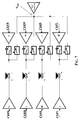
- a power amplifier of this invention particularly suited for car audio applications is depicted in Figure 7. It is substantially composed of four channels ChFR, ChRR, ChRL and ChFL driving a front right, rear right, rear left and front left loudspeakers, respectively.
- audio signals are fed to the inverting (or non inverting) input of the first operational amplifiers of the pairs of the front right and rear left channels that are always connected to the respective loads, while the audio signals are fed to the non inverting (or inverting) input of the operational amplifiers of the rear right and front left channels.
- the front right and front left audio signals ChFR and ChFL are substantially two random variables whose mean values are null.
- Figures 8, 9 and 10 show results of simulations of a four channel power amplifier of this invention with a standard four bridge power amplifier, that is a four bridge power amplifier composed of standard class AB operational amplifiers, and with a high efficiency self-configuring power amplifier according to the prior art, carried out with the software program MATLABTM.
- FIG. 8 the power consumption characteristics of the compared power amplifiers in function of the power delivered to the load for certain values of phase difference.
- the power amplifiers have four channels driven with sine signals of the same amplitude and each supplying four loads of 4 ⁇ .
- the first curve refers to a four channel standard power amplifier (SPA) whichever the phase difference between the input audio signals of the channels is.
- SPA standard power amplifier
- the same curve refers also to a self-configuring four channels high efficiency power amplifier (HI_EFF) of the prior art, as depicted in Figure 2 when the front and rear channels are outphased by 180°.
- the second curve, identified with the symbol “•”, refers to the same self-configuring four channels high efficiency power amplifier (HI_EFF) of Figure 2, when the front and rear channels are outphased by 90°.
- the third curve refers to the same four channels high efficiency power amplifier (HI_EFF) of the prior art when the input audio signals of the rear and front channels are in phase.
- the same curve also refers to the self-configuring four channel power amplifier of this invention (INV) as depicted in Figure 7 whichever the phase difference between the input audio signals of the front and rear channels is.
- the current absorbed by a front (rear) channel may be compensated only by the current flowing in the rear (front) channel connected to it when it is in phase thereto, but when the currents in the front and rear channels are in phase opposition, the total current absorbed by each voltage buffer OP1- and OP3- is twice the current circulating in each channel.
- the current in the front (rear) left channel compensates the current in the front (rear) right channel, and thus even in this case the current absorbed by the voltage buffer Vref_BUFFER is practically null.
- FIG 10 are shown the performances of the power amplifier of this invention depicted in Figure 7 when the audio signals input to the (front and rear) left channels are in phase with the audio signals input to the (front and rear) right channels and when there is a phase difference of 180°.
- the front and rear channels were outphased by 3ms and each channel had a 4 ⁇ load.
Priority Applications (2)
| Application Number | Priority Date | Filing Date | Title |
|---|---|---|---|
| EP03425358A EP1487100A1 (fr) | 2003-06-09 | 2003-06-09 | Amplificateur multicanal de puissance à sortie avec configuration automatique asymétrique ou en pont, indépendante de canaux, en particulier pour applications audio |
| US10/865,039 US7813515B2 (en) | 2003-06-09 | 2004-06-09 | Multi-channel power amplifier with channels independently self-configuring to a bridge or single-ended output, particularly for audio applications |
Applications Claiming Priority (1)
| Application Number | Priority Date | Filing Date | Title |
|---|---|---|---|
| EP03425358A EP1487100A1 (fr) | 2003-06-09 | 2003-06-09 | Amplificateur multicanal de puissance à sortie avec configuration automatique asymétrique ou en pont, indépendante de canaux, en particulier pour applications audio |
Publications (1)
| Publication Number | Publication Date |
|---|---|
| EP1487100A1 true EP1487100A1 (fr) | 2004-12-15 |
Family
ID=33186019
Family Applications (1)
| Application Number | Title | Priority Date | Filing Date |
|---|---|---|---|
| EP03425358A Withdrawn EP1487100A1 (fr) | 2003-06-09 | 2003-06-09 | Amplificateur multicanal de puissance à sortie avec configuration automatique asymétrique ou en pont, indépendante de canaux, en particulier pour applications audio |
Country Status (2)
| Country | Link |
|---|---|
| US (1) | US7813515B2 (fr) |
| EP (1) | EP1487100A1 (fr) |
Cited By (15)
| Publication number | Priority date | Publication date | Assignee | Title |
|---|---|---|---|---|
| WO2006075264A1 (fr) * | 2005-01-14 | 2006-07-20 | Koninklijke Philips Electronics N.V. | Dispositif de traitement de signaux et systeme audio et procede d'amplification en fonction de la frequence du niveau sonore des signaux audio |
| US7647030B2 (en) | 2004-10-22 | 2010-01-12 | Parkervision, Inc. | Multiple input single output (MISO) amplifier with circuit branch output tracking |
| US7750733B2 (en) | 2006-04-24 | 2010-07-06 | Parkervision, Inc. | Systems and methods of RF power transmission, modulation, and amplification, including embodiments for extending RF transmission bandwidth |
| US7885682B2 (en) | 2006-04-24 | 2011-02-08 | Parkervision, Inc. | Systems and methods of RF power transmission, modulation, and amplification, including architectural embodiments of same |
| US7911272B2 (en) | 2007-06-19 | 2011-03-22 | Parkervision, Inc. | Systems and methods of RF power transmission, modulation, and amplification, including blended control embodiments |
| EP2284993A3 (fr) * | 2009-08-14 | 2011-04-27 | Nxp B.V. | Amplificateur d'alimentation de pont à double mode commutable dynamique |
| US8013675B2 (en) | 2007-06-19 | 2011-09-06 | Parkervision, Inc. | Combiner-less multiple input single output (MISO) amplification with blended control |
| US8031804B2 (en) | 2006-04-24 | 2011-10-04 | Parkervision, Inc. | Systems and methods of RF tower transmission, modulation, and amplification, including embodiments for compensating for waveform distortion |
| US8315336B2 (en) | 2007-05-18 | 2012-11-20 | Parkervision, Inc. | Systems and methods of RF power transmission, modulation, and amplification, including a switching stage embodiment |
| US8334722B2 (en) | 2007-06-28 | 2012-12-18 | Parkervision, Inc. | Systems and methods of RF power transmission, modulation and amplification |
| US8755454B2 (en) | 2011-06-02 | 2014-06-17 | Parkervision, Inc. | Antenna control |
| US9106316B2 (en) | 2005-10-24 | 2015-08-11 | Parkervision, Inc. | Systems and methods of RF power transmission, modulation, and amplification |
| US9608677B2 (en) | 2005-10-24 | 2017-03-28 | Parker Vision, Inc | Systems and methods of RF power transmission, modulation, and amplification |
| US10278131B2 (en) | 2013-09-17 | 2019-04-30 | Parkervision, Inc. | Method, apparatus and system for rendering an information bearing function of time |
| WO2022038334A1 (fr) * | 2020-08-19 | 2022-02-24 | Cirrus Logic International Semiconductor Limited | Amplificateurs |
Families Citing this family (17)
| Publication number | Priority date | Publication date | Assignee | Title |
|---|---|---|---|---|
| EP1487100A1 (fr) * | 2003-06-09 | 2004-12-15 | STMicroelectronics S.r.l. | Amplificateur multicanal de puissance à sortie avec configuration automatique asymétrique ou en pont, indépendante de canaux, en particulier pour applications audio |
| US20060285702A1 (en) * | 2005-06-17 | 2006-12-21 | Felder Matthew D | Multi-mode driver circuit |
| US8677435B2 (en) * | 2008-11-26 | 2014-03-18 | Intel Corporation | Upstream power control for multiple transmit channels |
| US8073151B2 (en) * | 2009-04-28 | 2011-12-06 | Bose Corporation | Dynamically configurable ANR filter block topology |
| US8090114B2 (en) * | 2009-04-28 | 2012-01-03 | Bose Corporation | Convertible filter |
| US8165313B2 (en) * | 2009-04-28 | 2012-04-24 | Bose Corporation | ANR settings triple-buffering |
| US8184822B2 (en) * | 2009-04-28 | 2012-05-22 | Bose Corporation | ANR signal processing topology |
| US8073150B2 (en) * | 2009-04-28 | 2011-12-06 | Bose Corporation | Dynamically configurable ANR signal processing topology |
| JP6360453B2 (ja) | 2015-03-16 | 2018-07-18 | 株式会社東芝 | 電力増幅装置 |
| KR20160142034A (ko) * | 2015-06-02 | 2016-12-12 | 삼성전자주식회사 | 음성처리장치 및 그 제어방법 |
| KR102296174B1 (ko) | 2015-06-26 | 2021-08-31 | 삼성전자주식회사 | 전자 장치 및 그의 오디오 변환 방법 |
| US9660675B2 (en) * | 2015-10-13 | 2017-05-23 | Analog Devices Global | Digital predistortion and uptilt and cable communication |
| CN107846199B (zh) * | 2016-09-21 | 2022-09-30 | 北京普源精电科技有限公司 | 双通道功率放大器 |
| US10320340B1 (en) | 2018-01-11 | 2019-06-11 | Analog Devices Global Unlimited Company | Frequency-shaped digital predistortion |
| JP7204440B2 (ja) | 2018-11-21 | 2023-01-16 | 株式会社東芝 | 電力増幅装置 |
| JP7288415B2 (ja) | 2020-03-23 | 2023-06-07 | 株式会社東芝 | 電力増幅装置 |
| WO2023079260A1 (fr) * | 2021-11-05 | 2023-05-11 | Cirrus Logic International Semiconductor Limited | Circuits amplificateurs |
Citations (7)
| Publication number | Priority date | Publication date | Assignee | Title |
|---|---|---|---|---|
| US4330756A (en) * | 1979-06-27 | 1982-05-18 | Thomson-Csf | Audio-frequency amplifying device |
| EP0425878A2 (fr) * | 1989-10-31 | 1991-05-08 | STMicroelectronics S.r.l. | Amplificateur audio à haut rendement |
| US5621352A (en) * | 1993-02-24 | 1997-04-15 | Sgs-Thomson Microelectronics S.R.L. | Self-configurable, dual bridge, power amplifier |
| US5648742A (en) * | 1995-10-23 | 1997-07-15 | National Semiconductor Corporation | Amplifier circuit with reduced turn-on and turn-off transients |
| US5708390A (en) * | 1995-07-12 | 1998-01-13 | U.S. Philips Corporation | Signal amplifier arrangeable in two different configuration modes |
| US5729174A (en) * | 1995-07-12 | 1998-03-17 | U.S. Philips Corporation | Circuit arrangement for transmitting audio signals |
| EP0840444A1 (fr) * | 1996-10-31 | 1998-05-06 | SANYO ELECTRIC Co., Ltd. | Appareil amplificateur de puissance |
Family Cites Families (23)
| Publication number | Priority date | Publication date | Assignee | Title |
|---|---|---|---|---|
| US3881058A (en) * | 1973-05-23 | 1975-04-29 | Gte Sylvania Inc | Convertible amplifier system for single and multiple signal sources |
| JPS5320224Y2 (fr) * | 1973-08-01 | 1978-05-27 | ||
| US4494077A (en) * | 1981-12-02 | 1985-01-15 | Nippon Electric Co., Ltd. | Amplifier system switchable between two amplifying operations |
| US4894621A (en) * | 1988-06-13 | 1990-01-16 | Westinghouse Electric Corp. | Circuit for five level waveform synthesis |
| US5059920A (en) * | 1988-12-09 | 1991-10-22 | Synaptics, Incorporated | CMOS amplifier with offset adaptation |
| IT1243920B (it) * | 1990-11-20 | 1994-06-28 | Sgs Thomson Microelectronics | Amplificatore audio di potenza ad alta efficienza composto da due amplificatori con unica alimentazione. |
| US5194824A (en) * | 1992-01-23 | 1993-03-16 | Intel Corporation | 5V Rail-rail unity gain amplifier driving high capacitive load |
| US5414774A (en) * | 1993-02-12 | 1995-05-09 | Matsushita Electric Corporation Of America | Circuit and method for controlling an audio system |
| JP3414862B2 (ja) | 1993-09-20 | 2003-06-09 | ローム株式会社 | オーディオ信号電力増幅回路およびこれを用いるオーディオ装置 |
| US5654688A (en) * | 1995-04-14 | 1997-08-05 | Omega Research And Development, Inc. | Vehicle security system having enhanced remote transmitter security |
| US5973368A (en) * | 1996-06-05 | 1999-10-26 | Pearce; Lawrence G. | Monolithic class D amplifier |
| JP2003536339A (ja) | 2000-06-23 | 2003-12-02 | コーニンクレッカ フィリップス エレクトロニクス エヌ ヴィ | デュアルブリッジ増幅器 |
| US6549071B1 (en) * | 2000-09-12 | 2003-04-15 | Silicon Laboratories, Inc. | Power amplifier circuitry and method using an inductance coupled to power amplifier switching devices |
| US20020125941A1 (en) * | 2001-03-08 | 2002-09-12 | Nguyen Tranh To | High efficiency switching amplifiers |
| US6563377B2 (en) * | 2001-10-09 | 2003-05-13 | Evenstar, Inc. | Class D switching audio amplifier |
| US6552607B1 (en) * | 2001-11-12 | 2003-04-22 | Apogee Technology Inc. | Time division multiplexed PWM amplifier |
| EP1376857B1 (fr) * | 2002-06-14 | 2005-03-30 | Nokia Corporation | Circuit electronique pour amplificateur de puissance à découpage et méthode de commutation d'un étage de sortie d'un amplificateur de puissance à découpage |
| US7026866B2 (en) | 2003-03-28 | 2006-04-11 | Tripath Technology, Inc. | DC offset self-calibration system for a switching amplifier |
| US20040232978A1 (en) * | 2003-05-23 | 2004-11-25 | Easson Craig Alexander | Filterless class D amplifiers using spread spectrum PWM modulation |
| EP1487100A1 (fr) * | 2003-06-09 | 2004-12-15 | STMicroelectronics S.r.l. | Amplificateur multicanal de puissance à sortie avec configuration automatique asymétrique ou en pont, indépendante de canaux, en particulier pour applications audio |
| EP1496611A1 (fr) * | 2003-07-09 | 2005-01-12 | STMicroelectronics S.r.l. | Amplificateur multicanal de puissance à configuration automatique asymétrique ou en pont, en particulier pour applications audio |
| US7053718B2 (en) * | 2003-09-25 | 2006-05-30 | Silicon Laboratories Inc. | Stacked RF power amplifier |
| DE60317806T2 (de) * | 2003-12-23 | 2008-10-30 | Stmicroelectronics S.R.L., Agrate Brianza | Verfahren zum Verhindern abrupter Spannungsänderungen am Ausgang eines Verstärkerpaars und Regelschaltung für ein selbstkonfigurierendes Verstärkerpaar in einer Brückenkonfiguration |
-
2003
- 2003-06-09 EP EP03425358A patent/EP1487100A1/fr not_active Withdrawn
-
2004
- 2004-06-09 US US10/865,039 patent/US7813515B2/en active Active
Patent Citations (7)
| Publication number | Priority date | Publication date | Assignee | Title |
|---|---|---|---|---|
| US4330756A (en) * | 1979-06-27 | 1982-05-18 | Thomson-Csf | Audio-frequency amplifying device |
| EP0425878A2 (fr) * | 1989-10-31 | 1991-05-08 | STMicroelectronics S.r.l. | Amplificateur audio à haut rendement |
| US5621352A (en) * | 1993-02-24 | 1997-04-15 | Sgs-Thomson Microelectronics S.R.L. | Self-configurable, dual bridge, power amplifier |
| US5708390A (en) * | 1995-07-12 | 1998-01-13 | U.S. Philips Corporation | Signal amplifier arrangeable in two different configuration modes |
| US5729174A (en) * | 1995-07-12 | 1998-03-17 | U.S. Philips Corporation | Circuit arrangement for transmitting audio signals |
| US5648742A (en) * | 1995-10-23 | 1997-07-15 | National Semiconductor Corporation | Amplifier circuit with reduced turn-on and turn-off transients |
| EP0840444A1 (fr) * | 1996-10-31 | 1998-05-06 | SANYO ELECTRIC Co., Ltd. | Appareil amplificateur de puissance |
Cited By (60)
| Publication number | Priority date | Publication date | Assignee | Title |
|---|---|---|---|---|
| US7945224B2 (en) | 2004-10-22 | 2011-05-17 | Parkervision, Inc. | Systems and methods of RF power transmission, modulation, and amplification, including waveform distortion compensation embodiments |
| US8280321B2 (en) | 2004-10-22 | 2012-10-02 | Parkervision, Inc. | Systems and methods of RF power transmission, modulation, and amplification, including Cartesian-Polar-Cartesian-Polar (CPCP) embodiments |
| US7672650B2 (en) | 2004-10-22 | 2010-03-02 | Parkervision, Inc. | Systems and methods of RF power transmission, modulation, and amplification, including multiple input single output (MISO) amplifier embodiments comprising harmonic control circuitry |
| US9768733B2 (en) | 2004-10-22 | 2017-09-19 | Parker Vision, Inc. | Multiple input single output device with vector signal and bias signal inputs |
| US7835709B2 (en) | 2004-10-22 | 2010-11-16 | Parkervision, Inc. | RF power transmission, modulation, and amplification using multiple input single output (MISO) amplifiers to process phase angle and magnitude information |
| US7844235B2 (en) | 2004-10-22 | 2010-11-30 | Parkervision, Inc. | RF power transmission, modulation, and amplification, including harmonic control embodiments |
| US9197164B2 (en) | 2004-10-22 | 2015-11-24 | Parkervision, Inc. | RF power transmission, modulation, and amplification, including direct cartesian 2-branch embodiments |
| US9197163B2 (en) | 2004-10-22 | 2015-11-24 | Parkvision, Inc. | Systems, and methods of RF power transmission, modulation, and amplification, including embodiments for output stage protection |
| US9166528B2 (en) | 2004-10-22 | 2015-10-20 | Parkervision, Inc. | RF power transmission, modulation, and amplification embodiments |
| US7932776B2 (en) | 2004-10-22 | 2011-04-26 | Parkervision, Inc. | RF power transmission, modulation, and amplification embodiments |
| US8406711B2 (en) | 2004-10-22 | 2013-03-26 | Parkervision, Inc. | Systems and methods of RF power transmission, modulation, and amplification, including a Cartesian-Polar-Cartesian-Polar (CPCP) embodiment |
| US7647030B2 (en) | 2004-10-22 | 2010-01-12 | Parkervision, Inc. | Multiple input single output (MISO) amplifier with circuit branch output tracking |
| US8781418B2 (en) | 2004-10-22 | 2014-07-15 | Parkervision, Inc. | Power amplification based on phase angle controlled reference signal and amplitude control signal |
| US8913974B2 (en) | 2004-10-22 | 2014-12-16 | Parkervision, Inc. | RF power transmission, modulation, and amplification, including direct cartesian 2-branch embodiments |
| US8351870B2 (en) | 2004-10-22 | 2013-01-08 | Parkervision, Inc. | Systems and methods of RF power transmission, modulation, and amplification, including cartesian 4-branch embodiments |
| US8639196B2 (en) | 2004-10-22 | 2014-01-28 | Parkervision, Inc. | Control modules |
| US8626093B2 (en) | 2004-10-22 | 2014-01-07 | Parkervision, Inc. | RF power transmission, modulation, and amplification embodiments |
| US8577313B2 (en) | 2004-10-22 | 2013-11-05 | Parkervision, Inc. | Systems and methods of RF power transmission, modulation, and amplification, including output stage protection circuitry |
| US8447248B2 (en) | 2004-10-22 | 2013-05-21 | Parkervision, Inc. | RF power transmission, modulation, and amplification, including power control of multiple input single output (MISO) amplifiers |
| US8433264B2 (en) | 2004-10-22 | 2013-04-30 | Parkervision, Inc. | Multiple input single output (MISO) amplifier having multiple transistors whose output voltages substantially equal the amplifier output voltage |
| US8233858B2 (en) | 2004-10-22 | 2012-07-31 | Parkervision, Inc. | RF power transmission, modulation, and amplification embodiments, including control circuitry for controlling power amplifier output stages |
| US9143088B2 (en) | 2004-10-22 | 2015-09-22 | Parkervision, Inc. | Control modules |
| US8428527B2 (en) | 2004-10-22 | 2013-04-23 | Parkervision, Inc. | RF power transmission, modulation, and amplification, including direct cartesian 2-branch embodiments |
| WO2006075264A1 (fr) * | 2005-01-14 | 2006-07-20 | Koninklijke Philips Electronics N.V. | Dispositif de traitement de signaux et systeme audio et procede d'amplification en fonction de la frequence du niveau sonore des signaux audio |
| US9106316B2 (en) | 2005-10-24 | 2015-08-11 | Parkervision, Inc. | Systems and methods of RF power transmission, modulation, and amplification |
| US9608677B2 (en) | 2005-10-24 | 2017-03-28 | Parker Vision, Inc | Systems and methods of RF power transmission, modulation, and amplification |
| US9094085B2 (en) | 2005-10-24 | 2015-07-28 | Parkervision, Inc. | Control of MISO node |
| US9705540B2 (en) | 2005-10-24 | 2017-07-11 | Parker Vision, Inc. | Control of MISO node |
| US9614484B2 (en) | 2005-10-24 | 2017-04-04 | Parkervision, Inc. | Systems and methods of RF power transmission, modulation, and amplification, including control functions to transition an output of a MISO device |
| US9419692B2 (en) | 2005-10-24 | 2016-08-16 | Parkervision, Inc. | Antenna control |
| US7885682B2 (en) | 2006-04-24 | 2011-02-08 | Parkervision, Inc. | Systems and methods of RF power transmission, modulation, and amplification, including architectural embodiments of same |
| US8050353B2 (en) | 2006-04-24 | 2011-11-01 | Parkervision, Inc. | Systems and methods of RF power transmission, modulation, and amplification, including embodiments for compensating for waveform distortion |
| US8059749B2 (en) | 2006-04-24 | 2011-11-15 | Parkervision, Inc. | Systems and methods of RF power transmission, modulation, and amplification, including embodiments for compensating for waveform distortion |
| US7949365B2 (en) | 2006-04-24 | 2011-05-24 | Parkervision, Inc. | Systems and methods of RF power transmission, modulation, and amplification, including architectural embodiments of same |
| US8036306B2 (en) | 2006-04-24 | 2011-10-11 | Parkervision, Inc. | Systems and methods of RF power transmission, modulation and amplification, including embodiments for compensating for waveform distortion |
| US8031804B2 (en) | 2006-04-24 | 2011-10-04 | Parkervision, Inc. | Systems and methods of RF tower transmission, modulation, and amplification, including embodiments for compensating for waveform distortion |
| US8026764B2 (en) | 2006-04-24 | 2011-09-27 | Parkervision, Inc. | Generation and amplification of substantially constant envelope signals, including switching an output among a plurality of nodes |
| US7929989B2 (en) | 2006-04-24 | 2011-04-19 | Parkervision, Inc. | Systems and methods of RF power transmission, modulation, and amplification, including architectural embodiments of same |
| US9106500B2 (en) | 2006-04-24 | 2015-08-11 | Parkervision, Inc. | Systems and methods of RF power transmission, modulation, and amplification, including embodiments for error correction |
| US7937106B2 (en) | 2006-04-24 | 2011-05-03 | ParkerVision, Inc, | Systems and methods of RF power transmission, modulation, and amplification, including architectural embodiments of same |
| US7750733B2 (en) | 2006-04-24 | 2010-07-06 | Parkervision, Inc. | Systems and methods of RF power transmission, modulation, and amplification, including embodiments for extending RF transmission bandwidth |
| US8913691B2 (en) | 2006-08-24 | 2014-12-16 | Parkervision, Inc. | Controlling output power of multiple-input single-output (MISO) device |
| US8315336B2 (en) | 2007-05-18 | 2012-11-20 | Parkervision, Inc. | Systems and methods of RF power transmission, modulation, and amplification, including a switching stage embodiment |
| US8548093B2 (en) | 2007-05-18 | 2013-10-01 | Parkervision, Inc. | Power amplification based on frequency control signal |
| US8013675B2 (en) | 2007-06-19 | 2011-09-06 | Parkervision, Inc. | Combiner-less multiple input single output (MISO) amplification with blended control |
| US8766717B2 (en) | 2007-06-19 | 2014-07-01 | Parkervision, Inc. | Systems and methods of RF power transmission, modulation, and amplification, including varying weights of control signals |
| US8410849B2 (en) | 2007-06-19 | 2013-04-02 | Parkervision, Inc. | Systems and methods of RF power transmission, modulation, and amplification, including blended control embodiments |
| US7911272B2 (en) | 2007-06-19 | 2011-03-22 | Parkervision, Inc. | Systems and methods of RF power transmission, modulation, and amplification, including blended control embodiments |
| US8502600B2 (en) | 2007-06-19 | 2013-08-06 | Parkervision, Inc. | Combiner-less multiple input single output (MISO) amplification with blended control |
| US8461924B2 (en) | 2007-06-19 | 2013-06-11 | Parkervision, Inc. | Systems and methods of RF power transmission, modulation, and amplification, including embodiments for controlling a transimpedance node |
| US8884694B2 (en) | 2007-06-28 | 2014-11-11 | Parkervision, Inc. | Systems and methods of RF power transmission, modulation, and amplification |
| US8334722B2 (en) | 2007-06-28 | 2012-12-18 | Parkervision, Inc. | Systems and methods of RF power transmission, modulation and amplification |
| EP2284993A3 (fr) * | 2009-08-14 | 2011-04-27 | Nxp B.V. | Amplificateur d'alimentation de pont à double mode commutable dynamique |
| US8330539B2 (en) | 2009-08-14 | 2012-12-11 | Nxp B.V. | Dynamic switchable mode dual bridge power amplifier |
| US8755454B2 (en) | 2011-06-02 | 2014-06-17 | Parkervision, Inc. | Antenna control |
| US10278131B2 (en) | 2013-09-17 | 2019-04-30 | Parkervision, Inc. | Method, apparatus and system for rendering an information bearing function of time |
| WO2022038334A1 (fr) * | 2020-08-19 | 2022-02-24 | Cirrus Logic International Semiconductor Limited | Amplificateurs |
| US11271532B1 (en) | 2020-08-19 | 2022-03-08 | Cirrus Logic, Inc. | Amplifiers |
| GB2611931A (en) * | 2020-08-19 | 2023-04-19 | Cirrus Logic Int Semiconductor Ltd | Amplifiers |
| US11817833B2 (en) | 2020-08-19 | 2023-11-14 | Cirrus Logic Inc. | Amplifiers |
Also Published As
| Publication number | Publication date |
|---|---|
| US7813515B2 (en) | 2010-10-12 |
| US20050025323A1 (en) | 2005-02-03 |
Similar Documents
| Publication | Publication Date | Title |
|---|---|---|
| EP1487100A1 (fr) | Amplificateur multicanal de puissance à sortie avec configuration automatique asymétrique ou en pont, indépendante de canaux, en particulier pour applications audio | |
| JP5539557B2 (ja) | アンプ回路 | |
| JP3459109B2 (ja) | 自己構成可能な二元的ブリッジパワー増幅器 | |
| EP1456942B1 (fr) | Amplificateur a modulation d'impulsions en duree a multiplexage a repartition dans le temps | |
| US7167047B2 (en) | Multi-channel power amplifier self-configuring to a bridge or single-ended output, particularly for audio applications | |
| EP2284993B1 (fr) | Amplificateur d'alimentation de pont à double mode commutable dynamique | |
| US5654668A (en) | High efficiency bridge amplifier | |
| US7230482B2 (en) | Method of preventing abrupt voltage changes at the outputs of a pair of amplifiers and control circuit for a pair of amplifiers self-configuring in a bridge configuration | |
| JP5060369B2 (ja) | 出力バッファー回路 | |
| US5856759A (en) | Audio output amplifier with parallel class AB stages | |
| US7113032B2 (en) | Low distortion power amplifier and method of controlling a multi-channel power amplifier | |
| US9300261B2 (en) | Method and apparatus for efficient load biasing | |
| US11271532B1 (en) | Amplifiers | |
| CA3063958A1 (fr) | Amplificateur differentiel a base d'inverseur | |
| US20080285760A1 (en) | Audio system for improving a signal to noise ratio | |
| US11799426B2 (en) | Class D amplifier circuitry | |
| JP2012191671A (ja) | 出力バッファー回路 | |
| US20110060431A1 (en) | Audio output devices | |
| JP3392587B2 (ja) | 増幅回路 | |
| Humphreys | Chord CPM 2600 integrated amplifier | |
| JP2003110513A (ja) | 放送装置 |
Legal Events
| Date | Code | Title | Description |
|---|---|---|---|
| PUAI | Public reference made under article 153(3) epc to a published international application that has entered the european phase |
Free format text: ORIGINAL CODE: 0009012 |
|
| AK | Designated contracting states |
Kind code of ref document: A1 Designated state(s): AT BE BG CH CY CZ DE DK EE ES FI FR GB GR HU IE IT LI LU MC NL PT RO SE SI SK TR |
|
| AX | Request for extension of the european patent |
Extension state: AL LT LV MK |
|
| 17P | Request for examination filed |
Effective date: 20050602 |
|
| AKX | Designation fees paid |
Designated state(s): DE FR GB IT |
|
| RAP1 | Party data changed (applicant data changed or rights of an application transferred) |
Owner name: STMICROELECTRONICS SRL |
|
| STAA | Information on the status of an ep patent application or granted ep patent |
Free format text: STATUS: THE APPLICATION HAS BEEN WITHDRAWN |
|
| 18W | Application withdrawn |
Effective date: 20110518 |