EP1487098A1 - Motor temperature estimator and motor controller - Google Patents
Motor temperature estimator and motor controller Download PDFInfo
- Publication number
- EP1487098A1 EP1487098A1 EP03712735A EP03712735A EP1487098A1 EP 1487098 A1 EP1487098 A1 EP 1487098A1 EP 03712735 A EP03712735 A EP 03712735A EP 03712735 A EP03712735 A EP 03712735A EP 1487098 A1 EP1487098 A1 EP 1487098A1
- Authority
- EP
- European Patent Office
- Prior art keywords
- temperature
- electric motor
- coil
- current
- motor
- Prior art date
- Legal status (The legal status is an assumption and is not a legal conclusion. Google has not performed a legal analysis and makes no representation as to the accuracy of the status listed.)
- Granted
Links
Images


Classifications
-
- H—ELECTRICITY
- H02—GENERATION; CONVERSION OR DISTRIBUTION OF ELECTRIC POWER
- H02P—CONTROL OR REGULATION OF ELECTRIC MOTORS, ELECTRIC GENERATORS OR DYNAMO-ELECTRIC CONVERTERS; CONTROLLING TRANSFORMERS, REACTORS OR CHOKE COILS
- H02P23/00—Arrangements or methods for the control of AC motors characterised by a control method other than vector control
- H02P23/14—Estimation or adaptation of motor parameters, e.g. rotor time constant, flux, speed, current or voltage
-
- H—ELECTRICITY
- H02—GENERATION; CONVERSION OR DISTRIBUTION OF ELECTRIC POWER
- H02P—CONTROL OR REGULATION OF ELECTRIC MOTORS, ELECTRIC GENERATORS OR DYNAMO-ELECTRIC CONVERTERS; CONTROLLING TRANSFORMERS, REACTORS OR CHOKE COILS
- H02P21/00—Arrangements or methods for the control of electric machines by vector control, e.g. by control of field orientation
- H02P21/14—Estimation or adaptation of machine parameters, e.g. flux, current or voltage
- H02P21/16—Estimation of constants, e.g. the rotor time constant
Definitions
- the present invention relates to a motor-temperature estimation apparatus for estimating temperature of the housing, stator, coils, or the like of an electric motor, and to a motor control apparatus capable of limiting current flowing through an electric motor in accordance with coil temperature of the motor estimated by use of the motor-temperature estimation apparatus.
- a conventional apparatus includes a temperature sensor provided within an electric motor, and corrects drive current on the basis of temperature detected by use of the temperature sensor, to thereby compensate drop in permeability of the stator of the motor stemming from temperature increase. Further, in the publication, there is proposed a technique of estimating temperature of an electric motor through integration of drive current flowing through the motor.
- the present invention includes, as characteristic features, current detection means for detecting current flowing through a coil of an electric motor; determination means for determining whether the electric motor is in a rotating state or in a stopped state; and estimation calculation means for estimatingly calculating temperature of the electric motor on the basis of the detected current and through calculation which changes depending on results of the determination as to whether the electric motor is in the rotating state or in the stopped state.
- the temperature of the electric motor refers to, for example, temperature of a housing, temperature of a stator, or temperature of the coil.
- the estimation calculation means preferably includes square value calculation means for calculating a square value of the detected current; low-pass-filtering means for performing low-pass-filtering calculation for the calculated square value in a manner which changes depending on results of the determination as to whether the electric motor is in the rotating state or in the stopped state; temperature increase calculation means for calculating a temperature increase stemming from current flowing through the coil on the basis of the low-pass-filtered square value; and temperature calculation means for calculating temperature of the electric motor on the basis of the calculated temperature increase.
- the low-pass filtering delays change in the current square value (a parameter corresponding to quantity of generated heat).
- change in the current square value is rendered sharp; i.e., delay of change is reduced, as compared with the case where the electric motor is in the rotating state.
- the temperature calculation means may calculate temperature of the electric motor through addition, to ambient temperature of the electric motor, of the temperature increase calculated by means of the temperature increase calculation means.
- the motor temperature estimation apparatus may be configured in such a manner that the current detection means detects two phase currents converted from three phase currents; and the estimation calculation means estimatingly calculates temperature of the electric motor on the basis of the sum of respective square values of the two phase currents.
- the motor temperature estimation apparatus may be configured in such a manner that the current detection means detects three phase currents, and the estimation calculation means estimatingly calculates temperature of the electric motor on the basis of respective square values of the three phase currents.
- temperature of the electric motor is estimated through calculation which changes depending on results of the determination by the determination means as to whether the electric motor is in the rotating state or in the stopped state.
- temperature increase caused by current flowing through the coil in a stopped state is greater than temperature increase caused by current flowing through the coil in a rotating state. Therefore, according to the present invention, the difference in temperature increase caused by current flowing through the coil between the rotating state and the stopped state is taken into consideration, and thus estimation of temperature of the electric motor can be performed accurately.
- Another feature of the present invention resides in a motor control apparatus comprising current limiting means for limiting current flowing through the electric motor in accordance with the coil temperature estimated by means of the motor temperature estimation apparatus, which is configured as described above.
- the current limit means may be configured to limit current flowing through the electric motor to a predetermined limit value or less, when the estimated coil temperature exceeds a predetermined temperature.
- the limit value is gradually changed.
- FIG. 1 schematically shows the entire configuration of an electric power steering apparatus of a vehicle to which a motor-temperature estimation apparatus and a motor control apparatus according to the present invention are applied.
- the electric power steering apparatus includes, as an electric motor, a brushless motor 11, which is a three-phase synchronous permanent magnet motor.
- the brushless motor 11 includes a stator fixedly disposed within a housing, and forms a three-phase rotating magnetic field through supply of three-phase current to coils wound on the stator, whereby a rotor to which permanent magnets are fixed rotates in the three-phase rotating magnetic field in accordance with the three-phase current.
- the brushless motor 11 Upon rotation of the rotor, the brushless motor 11 imparts assist force to steering motion of front wheels generated by rotating operation of a steering wheel 12.
- a rack bar 14 is connected to the steering wheel 12 via a steering shaft 13 and a pinion gear (not shown), so that the rack bar 14 is displaced in an axial direction with rotation of the steering wheel 12.
- the rack bar 14 is also driven in the axial direction upon rotation of the brushless motor 11.
- the left and right front wheels are steerably connected to the opposite ends of the rack bar 14 via tie rods and knuckle arms (both are not shown).
- a torque sensor 15 is attached to a lower end portion of the steering shaft 13, and detects steering torque TR imparted to the steering shaft 13.
- a rotational angle sensor 16 formed by an encoder is attached to the brushless motor 11 in order to detect motor rotational angle (mechanical angle) ⁇ m.
- the rotational angle sensor 16 Upon rotation of the rotor of the brushless motor 11, the rotational angle sensor 16 outputs two-phase pulse-train signals having a phase difference of ⁇ /2, and a zero-phase pulse-train signal representing a reference rotational position.
- Data indicating torque TR detected by means of the steering toque sensor 15 and motor rotational angle ⁇ m detected by means of the rotational angle sensor 16 are supplied to an electronic control circuit unit ECU (indicated by a chain-line frame in FIG. 1).
- data indicating vehicle speed V detected by means of a vehicle speed sensor 17 is supplied to the electronic control circuit unit ECU.
- the electronic control circuit unit ECU controls three-phase current (assist current) supplied to the coils of the brushless motor 11, and includes an assist-current calculation section 21 for receiving the data indicating vehicle speed V and steering torque TR.
- the assist-current calculation section 21 calculates two instruction phase currents Id* and Iq* corresponding to assist torque which increases with steering torque TR and decreases with increase of vehicle speed V.
- these two instruction phase currents Id* and Iq* correspond to a d-axis and a q-axis, respectively, of a rotating coordinate system which is synchronous with rotating magnetic flux produced by a permanent magnet on the rotor of the brushless motor 11, where the d-axis extends in the same direction as that of the permanent magnet, and the q-axis extends in a direction perpendicular thereto.
- the instruction current Id* is set to "0.”
- Two phase currents Id and Iq which are converted from three phase currents lu, Iv, and Iw flowing through the coils of the brushless motor 11, are supplied to the feedback control section 23.
- a current sensor 24 detects the three phase currents Iu, Iv, and Iw.
- a 3-phase/2-phase conversion section 25 converts the three phase currents Iu, Iv, and Iw to the two phase currents Id and Iq.
- a rotational angle conversion section 26 which converts motor rotational angle ⁇ m to electrical angle ⁇ e, is connected to the 3-phase/2-phase conversion section 25.
- the feedback control section 23 produces difference signals Id* - Id and Iq* - Iq, which represent respective differences between the two instruction phase currents Id* and Iq* and the two phase currents Id and Iq, so as to feedback-control the three phase currents Iu, Iv, and Iw flowing through the coils of the brushless motor 11.
- the two phase difference signals Id* - Id and Iq* - Iq are converted to three phase signals by means of a 2-phase/3-phase conversion section 27; and the thus-obtained three phase signals are supplied to a PWM control circuit 28.
- the electrical angle ⁇ e output from the rotational angle conversion section 26 is supplied to the 2-phase/3-phase conversion section 27.
- the PWM control circuit 28 produces pulse-width modulation (PWM) control signals corresponding to the difference signals Id* - Id and Iq* - Iq, and supplies them to a drive circuit 31.
- PWM pulse-width modulation
- the drive circuit 31 switches battery voltage Ebt output from a battery 32 in accordance with the PWM control signals so as to supply three phase currents Iu, Iv, and Iw, which correspond to the PWM control signals, to the coils of the brushless motor 11 via an electromagnetic relay 33.
- the electromagnetic relay 33 is controlled by means of a relay control circuit 34, which will be described later in detail, and is usually in an on state after an ignition switch 35 is turned on. Therefore, during periods in which steering assist by the brushless motor 11 is effected, normally, the PWM-controlled three phase currents Iu, Iv, and Iw flow through the coils of the brushless motor 11.
- the brushless motor 11 imparts assist torque corresponding to the steering torque TR and the vehicle speed V for steering operation of the steering wheel 12 by a driver.
- the above-described assist-current calculation section 21, current limit section 22, feedback control section 23, 3-phase/2-phase conversion section 25, rotational angle conversion section 26, and 2-phase/3-phase conversion section 27 within the electronic control circuit unit ECU may be formed by hardware; however, in the present embodiment, these sections are realized through execution of a microcomputer program. In other words, these sections 21 to 23 and 25 to 27 represent, in the form of a block diagram, various functions realized through execution of the microcomputer program.
- the motor overheat prevention apparatus includes a motor overheat prevention control section 40, which is disposed in the electronic control circuit unit ECU.
- the motor overheat prevention control section 40 estimates temperatures of the housing, stator, and coils of the brushless motor 11, and limits current flowing through the brushless motor 11 when the coil temperature is high.
- An ambient temperature sensor 51, a board temperature sensor 52, a speed conversion section 53, and a potentiometer 54 are connected to the input side of the motor overheat prevention control section 40.
- the ambient temperature sensor 51 is attached to the steering torque sensor 15, and detects ambient temperature TPtr of a location where the brushless motor 11 is disposed (outside air temperature).
- the ambient temperature sensor 51 is not necessarily required to be attached to the steering torque sensor 15, and may detect temperature at an arbitrary location near the brushless motor 11, so long as the ambient temperature sensor 51 can detect temperature at a location other than locations at which temperature increases due to influence of current flowing through the motor 11.
- the board temperature sensor 52 is attached to a printed circuit board, on which the electronic control circuit unit ECU is disposed, and detects printed board temperature TPbd.
- the printed board temperature TPbd is used to estimate temperature drop which relates to ambient temperature and time between stop of operation of the brushless motor 11 and resumption thereof. Therefore, a temperature sensor for detecting temperature of a component other than the printed circuit board may be used instead of the board temperature sensor 52, so long as the alternative temperature sensor can detect temperature of a portion whose temperature increases due to influence of current flowing through the motor 11.
- a temperature sensor for detecting temperature of an element which partially constitutes the electronic control circuit unit ECU may be used in place of the board temperature sensor 52.
- the speed conversion section 53 differentiates the electrical angle ⁇ e output from the rotational angle conversion section 26 to thereby output a signal indicative of rotational speed RV of the rotor of the brushless motor 11.
- the potentiometer 54 is connected to the battery 32 via the ignition switch 35, and outputs, for detection of on-off state of the ignition switch 35, a voltage corresponding to the battery voltage Ebt supplied to the potentiometer via the ignition switch 35.
- the current limit section 22, the relay control circuit 34, and a power supply circuit 55 are connected to the output side of the motor overheat prevention control section 40.
- the current limit section 22 receives motor current limit value ILm from the motor overheat prevention control section 40, and limits the instruction current Iq* (Id* is "0"), calculated at the assist-current calculation section 21, to the motor current limit value ILm or less, whereby current flowing through the coils of the brushless motor 11 is limited so as not to exceed the motor current limit value ILm.
- phase currents Iu, Iv, and Iw flow through the brushless motor 11; therefore, the three phase currents Iu, Iv, and Iw are limited so as not to exceed corresponding phase current values which are converted from the motor current limit value ILm.
- the relay control circuit 34 turns the electromagnetic relay 33 on and off under the control of the motor overheat prevention control section 40, the electromagnetic relay 33 being provided in a current path to the brushless motor 11.
- the power supply circuit 55 is connected to the battery 32. Under the control of the motor overheat prevention control section 40, the power supply circuit 55 steps the voltage from the battery 32 up or down so as to supply operation voltages for various control sections and circuits.
- a writable, nonvolatile memory (hereinafter referred to as EEPROM) 60 is connected to the motor overheat prevention control section 40.
- the EEPROM 60 is used to store, at the end of operation of the brushless motor 11, various parameters which are needed to estimate temperatures of the housing, stator, and coils of the brushless motor 11 while the motor is in operation.
- the motor overheat prevention control section 40 and the speed conversion section 53 may be formed by hardware; however, in the present embodiment, these sections are realized through execution of a microcomputer program. In other words, these sections 40 and 53 represent, in the form of a block diagram, various functions realized through execution of the microcomputer program.
- an ignition-on detection section 41 a detects the turn-on operation of the ignition switch 35 from an increase in the battery voltage Ebt output from the potentiometer 54.
- the battery voltage Ebt output from the potentiometer 54 undergoes analog-to-digital conversion performed by means of an unillustrated A/D converter.
- the motor overheat prevention control section 40 performs unillustrated initial check processing.
- a data read-write processing section 42 reads various stored data from the EEPROM 60, and supplies them to an initial temperature correction calculation section 43.
- the initial temperature correction calculation section 43 calculates initial values of mass estimation temperature TPma, which is a variable representing estimated temperature of the mass portion (corresponding to the housing and stator) of the brushless motor 11, and coil estimation temperature TPco, which is a variable representing estimated temperature of the coils.
- a temperature estimation calculation section 44 starts to estimate, at predetermined short intervals, values of mass estimation temperature TPma and coil estimation temperature TPco by making use of these initial values and a motor current square value Ismt calculated at a motor-current square value calculation section 45.
- a first current limit value calculation section 46a, a second current limit value calculation section 46b, and a minimum-value selection section 46c start control for limiting current flowing through the brushless motor 11 on the basis of the value of coil estimation temperature TPco.
- initial value calculation and estimation calculation for mass estimation temperature TPma and coil estimation temperature TPco, and operation for limiting the current of the brushless motor 11 will be described later in detail.
- the data read-write processing section 42 Immediately after start of control of the brushless motor 11 (immediately after time t2), the data read-write processing section 42 writes predetermined large values in the EEPROM 60 as tentative data of respective storage values TPtrep, TPmaep, TPcoep of ambient temperature TPtr, mass estimation temperature TPma, and coil estimation temperature TPco, in preparation for the case where data writing after that time is impossible.
- the reason why the large values are used is to avoid the possibility that in future estimation, ambient temperature TPtr and mass estimation temperature TPma are calculated as temperatures lower than actual temperatures.
- an ignition-off detection section 41 b detects the turn-off operation of the ignition switch 35 from a decrease in the battery voltage Ebt output from the potentiometer 54. In this case, the ignition-off detection section 41 b detects the turn-off of the ignition switch 35 upon satisfaction of conditions that the battery voltage Ebt is lower than a predetermined value and that this low voltage state continues for at least a predetermined period.
- the motor overheat prevention control section 40 performs various controls (IG off control) in relation to the turn-off of the ignition switch 35.
- IG off control As the ignition off control (IG off control), the data read-write processing section 42 writes, immediately after the detection of the turn-off of the ignition switch 35 (immediately after time t3), the present values of mass estimation temperature TPma and coil estimation temperature TPco in the EEPROM 60 as mass temperature storage value TPmaep and coil temperature storage value TPcoep. This processing is performed in preparation for the case in which writing of data in the EEPROM 60 becomes impossible at the time of power off.
- a power-off control section 47 sets a wait time before power off.
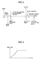
- a wait-time table stored in the power-off control section 47 is referred to, and a wait time corresponding to coil estimation temperature TPco at that time is set.
- the wait time table stores wait time which increases with coil estimation temperature TPco.
- the power-off control section 47 starts measurement of the wait time set as described above, and outputs to the relay control circuit 34 a relay off signal Roff for turning the electromagnetic relay 33 off.
- the relay control circuit 34 turns the electromagnetic relay 33 off, whereby no current flows through the brushless motor 11 after that time. This operation is performed so as to minimize current flowing within the electronic control circuit unit ECU.
- the power-off control section 47 When the power-off control section 47 completes the measurement of the set wait time, at time t5, the power-off control section 47 instructs the data read-write processing section 42 to write data.
- the data read-write processing section 42 writes ambient temperature TPtr and printed board temperature TPbd at that time in the EEPROM 60 as ambient temperature storage value TPtrep and printed board temperature storage value TPbdep, respectively.
- the data read-write processing section 42 writes the difference TPma-TPtr between mass estimation temperature TPma and ambient temperature TPtr at that time and the difference TPco-TPma between coil estimation temperature TPco and mass estimation temperature TPma at that time in the EEPROM 60 as mass-ambient temperature difference storage value ⁇ TPmtep and coil-mass temperature difference storage value ⁇ TPcmep, respectively.
- the power-off control section 47 After the above data are written in the EEPROM 60 as ambient temperature storage value TPtrep, printed board temperature storage value TPbdep, mass-ambient temperature difference storage value ⁇ TPmtep, and coil-mass temperature difference storage value ⁇ TPcmep, the power-off control section 47 outputs a power off signal Poff to the power supply circuit 55. In response thereto, the power supply circuit 55 stops supply of power to all the circuits. The reason why wait time is provided before power off is to wait for mass estimation temperature TPma and coil estimation temperature TPco to decrease to some degree. Needless to say, during this wait period as well, estimation calculation for determining mass estimation temperature TPma and coil estimation temperature TPco is continued. This operation improves accuracy in estimating mass estimation temperature TPma and coil estimation temperature TPco in a state in which the ignition switch 35 is turned on next time.
- the initial value calculation and estimation calculation for mass estimation temperature TPma and coil estimation temperature TPco are performed in the initial temperature correction calculation section 43.
- ambient temperature TPtr and printed board temperature TPbd at that time are used along with ambient temperature storage value TPtrep, printed board temperature storage value TPbdep, mass-ambient temperature difference storage value ⁇ TPmtep, and coil-mass temperature difference storage value ⁇ TPcmep.
- ambient temperature storage value TPtrep ambient temperature storage value
- mass temperature storage value TPmaep mass temperature storage value
- TPcoep coil temperature storage value
- These storage values TPtrep, TPbdep, ⁇ TPmtep, ⁇ TPcmep, TPmaep, and TPcoep are stored in the EEPROM 60 as described above, and in response to turn-on of the ignition switch 35, are read out by the data read-write processing section 42 and supplied to the initial temperature correction calculation section 43.
- the initial temperature correction calculation section 43 calculates a mass temperature initial correction coefficient Ktpm and a coil temperature initial correction coefficient Ktpc corresponding to the printed board temperature change ⁇ TPbd.
- These mass temperature initial correction coefficient map and coil temperature initial correction coefficient map respectively represent changes in mass temperature and coil temperature corresponding to change in printed board temperature TPbd, and decrease as the printed board temperature change ⁇ TPbd increases, as shown in FIGS. 5A and 5B, respectively.
- these maps can be obtained empirically or calculated from the relation between heat radiation of the printed board and heat radiation of the mass portion and coils.
- the mass temperature initial correction coefficient Ktpm and the coil temperature initial correction coefficient Ktpc are calculated by making use of printed board temperature change ⁇ TPbd.
- the mass temperature initial correction coefficient Ktpm and the coil temperature initial correction coefficient Ktpc may be calculated by making use of ambient temperature change ⁇ TPtr.
- there are prepared a mass temperature initial correction coefficient map and a coil temperature initial correction coefficient map which respectively define mass temperature initial correction coefficient Ktpm and coil temperature initial correction coefficient Ktpc which change in accordance with change in ambient temperature TPtr.
- a first special situation is the case where data were failed to be written in the EEPROM 60 at the time of previous power off (immediately before time t5 of FIG. 3); that is, the case where previous ambient temperature storage value TPtrep, printed board temperature storage value TPbdep, mass-ambient temperature difference storage value ⁇ TPmtep, and coil-mass temperature difference storage value ⁇ TPcmep cannot be read out of the EEPROM 60.
- calculation of the above-mentioned Equations (1) and (2) is impossible.
- mass estimation temperature TPma and coil estimation temperature TPco are initially set to the mass temperature storage value TPmaep and coil temperature storage value TPcoep written in the EEPROM 60 at the time of turn off of the ignition switch 35 (at time t3 of FIG. 3). Moreover, in the case where even the mass temperature storage value TPmaep and the coil temperature storage value TPcoep were not written in the EEPROM 60, the tentative data written in the EEPROM 60 at time t2 of FIG. 3 are utilized.
- a second special situation is the case where printed board temperature TPbd assumes an anomalous value.
- calculation of the mass temperature initial correction coefficient Ktpm and the coil temperature initial correction coefficient Ktpc corresponding to the printed board temperature change ⁇ TPbd is impossible, and calculation of the above-mentioned Equations (1) and (2) is impossible.
- mass estimation temperature TPma and coil estimation temperature TPco are initially set to the mass temperature storage value TPmaep and coil temperature storage value TPcoep, respectively.
- a third special situation is the case where ambient temperature TPtr is not higher than a considerably low, predetermined temperature (e.g., not greater than 0°C).
- ambient temperature TPtr is considerably low, and the temperatures of the housing, stator, and coils of the brushless motor 11 are expected to be equal to the considerably low ambient temperature TPtr.
- mass estimation temperature TPma and coil estimation temperature TPco are initially set to the ambient temperature TPtr.
- a fourth special situation is the case where the vehicle is placed in the blazing sun in summer. Existence of this situation is determined on the basis of conditions such that ambient temperature TPtr is higher than ambient temperature storage value TPtrep, printed board temperature TPbd is not lower than a considerably high, predetermined temperature (e.g., not lower than 85°C), or ambient temperature TPtr is not lower than a considerably high, predetermined temperature (e.g., not lower than 85°C).
- mass estimation temperature TPma is initially set to the higher one of ambient temperature TPtr and mass temperature storage value TPmaep.
- coil estimation temperature TPco is initially set to the higher one of ambient temperature TPtr and coil temperature storage value TPcoep.
- the temperature estimation calculation section 44 calculates the temperatures of the housing (or stator) and coils of the brushless motor 11, which change with passage of time, while repeatedly updating the initially set mass estimation temperature TPma and the initially set coil estimation temperature TPco.
- rotational speed RV and motor-current square value Ismt are utilized.
- the rotational speed RV is rotational speed of the brushless motor 11 calculated in the speed conversion section 53.
- the motor-current square value Ismt is equal to the sum Id 2 + Iq 2 of square values of two phase currents Id and Iq flowing through the brushless motor 11, the square values being calculated in the motor-current square value calculation section 45.
- the motor-current square value Ismt is proportional to quantity of heat generated by current flowing through the coils of the brushless motor 11.
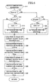
- Estimation calculation processing that the temperature estimation calculation section 44 performs to obtain mass estimation temperature TPma and coil estimation temperature TPco is shown as a motor-temperature estimation program in the flowchart of FIG. 6.
- This motor-temperature estimation program consists of steps S10 to S38 and is repeatedly executed at short time intervals (e.g., 80 milliseconds).
- step S12 determines in step S12 whether a rotation flag RVF is "0."
- This rotation flag RVF indicates that the brushless motor 11 is currently rotating when its value is “1” and indicates that the brushless motor 11 is currently stopped when its value is “0.”
- the calculation section 44 makes a "Yes" determination in step S12, and processing proceeds to step S14.
- the calculation section 44 determines whether the rotational speed RV is not less than a predetermined low speed RV2 (e.g., 0.3 radian/sec).
- step S14 When the rotational speed RV is not less than the predetermined low speed RV2, the calculation section 44 makes a "Yes” determination in step S14, proceeds to step S16 so as to change the rotation flag RVF to "1," and then proceeds to step S18.
- step S14 When the rotational speed RV is less than the predetermined low speed RV2, the calculation section 44 makes a "No" determination in step S14, and processing proceeds to step S26.
- step S18 the calculation section 44 selects parameters for rotation (parameters in relation to rotation periods of the brushless motor 11) as parameters to be used in the below-described calculation processing.
- parameters include current mass delay count Nima, current mass temperature correction coefficient Kima, current coil delay count Nico, and current coil temperature correction coefficient Kico.
- step S20 the calculation section 44 determines whether the rotational speed RV is not greater than a predetermined speed RV1 (e.g., 0.1 radian/sec) smaller than the predetermined speed RV2.
- a predetermined speed RV1 e.g., 0.1 radian/sec
- the reason why the predetermined speed RV1 is set smaller than the predetermined speed RV2 is to provide hysteresis in detection of rotating state and stopped state of the brushless motor 11 to thereby avoid hunting.
- step S20 When the rotational speed RV is not greater than the predetermined speed RV1, the calculation section 44 makes a "Yes” determination in step S20, proceeds to step S22 so as to change the rotation flag RVF to "0,” and then proceeds to step S24.
- step S24 When the rotational speed RV is greater than the predetermined speed RV1, the calculation section 44 makes a "No" determination in step S20, and processing proceeds to step S26.
- step S24 the calculation section 44 selects parameters for stoppage (parameters in relation to stop periods of the brushless motor 11) as parameters to be used in the below-described calculation processing.
- the various parameters used in the calculation processing are set to different values for rotating periods and stop periods of the brushless motor 11.
- the current mass delay count Nima and the current coil delay count Nico delay changes in values in estimation calculation for mass estimation temperature TPma and coil estimation temperature TPco. That is, these parameters smooth changes in these values.
- the current mass temperature correction coefficient Kima and the current coil temperature correction coefficient Kico are parameters which represent the degree of influence of current square value for mass Isma and current square value for coils Isco on mass estimation temperature TPma and coil estimation temperature TPco.
- current square value for mass Isma and current square value for coils Isco correspond to respective quantities of heat generation which cause temperature increases in the mass portion and the coils, and are values obtained through low-pass filtering of motor current square value Ismt.
- step S26 the calculation section 44 of the motor overheat prevention control section 40 performs low-pass-filtering calculation of the following Equation (3), which uses motor current square value Ismt and current mass delay count Niam, to thereby obtain current square value for mass Isma.
- Isma(n) Isma (n-1) + ⁇ Ismt - Isma(n-1) ⁇ /Nima
- Isma(n) represents the present calculated value (present value) of current square value for mass Isma
- Isma(n-1) represents the previous calculated value (value at time 80 milliseconds before the present time) of current square value for mass Isma (see FIG. 7).
- the calculation section 44 calculates mass temperature increase ⁇ TPma through execution of calculation according to the following Equation (4), which uses the calculated current square value for mass Isma(n) and the current mass temperature correction coefficient Kima.
- ⁇ TPma a ⁇ Kima ⁇ Isma(n)
- Equation (4) "a" is a predetermined proportionality constant.
- the calculation section 44 calculates mass estimation temperature TPma through execution of calculation according to the following Equation (5), which uses the calculated mass temperature increase ⁇ TPma and ambient temperature TPtr.
- TPma TPtr + ⁇ TPma
- step S32 the calculation section 44 performs low-pass-filtering calculation of the following Equation (6), which uses motor current square value Ismt and current coil delay count Nico, to thereby obtain current square value for coils Isco.
- Isco(n) Isco (n-1) + ⁇ Ismt - Isco(n-1) ⁇ /Nico
- Isco(n) represents the present calculated value (present value) of current square value for coils Isco
- Isco(n-1) represents the previous calculated value (value at time 80 milliseconds before the present time) of current square value for coils Isco (see FIG. 7).
- the calculation section 44 calculates coil temperature increase ⁇ TPco through execution of calculation according to the following Equation (7), which uses the calculated current square value for coils Isco(n) and the current coil temperature correction coefficient Kico.
- ⁇ TPco b ⁇ Kico ⁇ Isco(n)
- step S36 the calculation section 44 calculates coil estimation temperature TPco through execution of calculation according to the following Equation (8), which uses the calculated coil temperature increase ⁇ TPco and mass estimation temperature TPma. After that, in step S38, the calculation section 44 ends the motor-temperature estimation program.
- TPco TPma + ⁇ TPco
- temperatures of the mass portion and coils of the brushless motor 11 are estimated in different manners of calculation between the case where the brushless motor 11 is rotating and the case where the brushless motor 11 is stopped; i.e., in consideration of difference in temperature increase caused by current flowing through the coils between the case where the brushless motor 11 is rotating and the case where the brushless motor 11 is stopped.
- temperatures of the mass portion and coils of the brushless motor 11 can be detected by means of a simple configuration, without necessity of incorporating a temperature sensor in the brushless motor 11.
- the mass portion and the coils which differ in heat radiation and heat generation characteristics are separated from each other, and calculation is performed while different parameters are used for the mass portion and the coils. Therefore, coil temperature can be detected accurately.
- the value of coil estimation temperature TPco calculated in the temperature estimation calculation section 44 is supplied to the first current limit value calculation section 46a and the second current limit value calculation section 46b.
- the first current limit value calculation section 46a calculates a first current limit value IL1 corresponding to the calculated value of coil estimation temperature TPco with reference to a current limit value table.
- This current limit value table is provided in the first current limit value calculation section 46a, and, as shown in FIG. 8, the table stores the first current limit value IL1, which decreases with increase in coil estimation temperature TPco.
- the second current limit value calculation section 46b calculates a second current limit value IL2 which supplements the first current limit value IL1 calculated in the first current limit value calculation section 46a and forcedly limits current when coil estimation temperature TPco becomes considerably high.
- the second current limit value calculation section 46b sets a target current limit value ILtg to a predetermined small value, and repeatedly executes the calculation (low-pass filtering processing) of the following Equation (9) at predetermined short intervals.
- IL2(n) IL2(n-1) + Kf1 ⁇ (ILtg - IL2(n-1)
- Equation (9) IL2(n) represents the present calculated value (present value) of second current limit value IL2, and IL2(n-1) represents the previous calculated value (value at time 80 milliseconds before the present time) of second current limit value IL2.
- the coefficient Kf1 is a predetermined constant less than "1.”
- the second current limit value calculation section 46b sets the target current limit value ILtg to a predetermined value (e.g., 60 A), and repeatedly executes the calculation of Equation (9). As a result, the above-mentioned forced current limit is cancelled, and the second current limit value IL2 gradually increases to the target current limit value ILtg set to the predetermined current value.
- a predetermined value e.g. 60 A
- the thus calculated first and second current limit values IL1 and IL2 are supplied to the minimum value selection section 46c.
- the minimum value selection section 46c selects the smaller one of the first and second current limit values IL1 and IL2 to be used as a motor-current limit value ILm.
- the thus-determined motor-current limit value ILm is supplied to the current limit section 22.
- the current limit section 22 limits three phase currents lu, Iv, and Iw flowing through the brushless motor 11 in accordance with the motor-current limit value ILm.
- the current supplied to the brushless motor 11 is limited, whereby the coil temperature does not increase. This prevents breakage of insulation, which breakage would otherwise occur because of melting of coating of the coils.
- the second current limit value IL2 is taken into consideration, whereby increase in coil temperature of the brushless motor 11 is properly suppressed even in the case where the limit of current of the brushless motor 11 by means of the first current limit value IL1 results in an increase in coil temperature.
- the second current limit value IL2 when coil estimation temperature TPco exceeds the predetermined temperature, current flowing through the brushless motor 11 is forcedly limited to the predetermined limit value or less. Accordingly, temperature increase of the coils of the brushless motor 11 can be suppressed without fail. Moreover, when current flowing through the brushless motor 11 is limited to the predetermined limit value or less, the limit value changes gradually. This operation avoids abrupt change in output of the brushless motor 11.
- coil temperature may be estimated on a phase-by-phase fashion on the basis of three phase currents lu, Iv, and Iw actually flowing through the brushless motor 11.
- the motor overheat prevention control section 40 receives data indicative of three phase currents lu, Iv, and Iw of the brushless motor 11 detected by means of the current sensor 24.
- the motor overheat prevention control section 40 calculates respective current square values Iu 2 , Iv 2 , and Iw 2 of the three phases, and performs, on the respective current square values Iu 2 , Iv 2 , and Iw 2 , the calculation processing applied to the motor-current square value Ismt of the above-described embodiment, to thereby estimate the respective coil temperatures of the individual phases. Subsequently, of the coil temperatures of the individual phases, the highest coil temperature is selected, and current flowing through the brushless motor 11 is limited on the basis of the selected coil temperature.
- mass estimation temperature TPma of the mass portion (housing, stator, etc.) is utilized in the course of calculation of coil estimation temperature TPco of the brushless motor 11.
- mass estimation temperature TPma may be used to correct a decrease in permeability of the stator caused by temperature increase of the brushless motor 11. In this case, three phase currents of the brushless motor 11 are increased as mass estimation temperature TPma increases.
- phase currents lu, Iv, and Iw are detected by means of the current sensor 24.
- only two phase currents are detected by means of the current sensor 24, and the remaining phase current is calculated by use of the detected two phase currents.
- two phase currents lu and Iv are detected by means of the current sensor 24, and the remaining phase current Iw is calculated by the formula -(Iu + Iv).
- the present invention is applied to the brushless motor 11.
- the present invention can be applied to various types of motors other than the brushless motor 11.
- the present invention is applied to an electric motor for imparting assist torque to rotating operation of the steering wheel 12 of the vehicle.
- the present invention can be applied to other various types of electric motors mounted on the vehicle; for example, an electric motor which is incorporated in a steer-by-wire-type steering apparatus and imparts steering torque to wheels.
- the present invention can be applied to electric motors incorporated in various apparatus other than vehicles.
Abstract
Description
- The present invention relates to a motor-temperature estimation apparatus for estimating temperature of the housing, stator, coils, or the like of an electric motor, and to a motor control apparatus capable of limiting current flowing through an electric motor in accordance with coil temperature of the motor estimated by use of the motor-temperature estimation apparatus.
- As shown in Japanese Patent Application Laid-Open (kokai) No. H10-67335, a conventional apparatus includes a temperature sensor provided within an electric motor, and corrects drive current on the basis of temperature detected by use of the temperature sensor, to thereby compensate drop in permeability of the stator of the motor stemming from temperature increase. Further, in the publication, there is proposed a technique of estimating temperature of an electric motor through integration of drive current flowing through the motor.
- The above-described technique which uses a temperature sensor incorporated in an electric motor is not preferable from the viewpoint of cost and easiness of mounting of the motor onto an apparatus which uses the motor, because of the necessity of providing a temperature sensor and connection wires for connecting the temperature sensor and a control circuit of the motor. Although the above-mentioned patent publication proposes a technique of estimating temperature of an electric motor through integration of drive current flowing through the motor, it does not describe the details of the technique.
- The present invention has been accomplished in order to cope with the above-described problem, and an object of the present invention is to provide a motor-temperature estimation apparatus which can accurately detect temperature of the housing, stator, coils, or the like of an electric motor, without the necessity of incorporating a temperature sensor into the motor. Another object of the present invention is to provide a motor control apparatus which can limit current flowing through an electric motor in accordance with coil temperature of the motor estimated by use of the motor-temperature estimation apparatus, to thereby reliably suppress temperature rise of the coils of the motor.
- In order to achieve the above object, the present invention includes, as characteristic features, current detection means for detecting current flowing through a coil of an electric motor; determination means for determining whether the electric motor is in a rotating state or in a stopped state; and estimation calculation means for estimatingly calculating temperature of the electric motor on the basis of the detected current and through calculation which changes depending on results of the determination as to whether the electric motor is in the rotating state or in the stopped state. In this case, the temperature of the electric motor refers to, for example, temperature of a housing, temperature of a stator, or temperature of the coil.
- The estimation calculation means preferably includes square value calculation means for calculating a square value of the detected current; low-pass-filtering means for performing low-pass-filtering calculation for the calculated square value in a manner which changes depending on results of the determination as to whether the electric motor is in the rotating state or in the stopped state; temperature increase calculation means for calculating a temperature increase stemming from current flowing through the coil on the basis of the low-pass-filtered square value; and temperature calculation means for calculating temperature of the electric motor on the basis of the calculated temperature increase.
- More specifically, the low-pass filtering delays (in other words, smoothes) change in the current square value (a parameter corresponding to quantity of generated heat). Preferably, when the electric motor is in the stopped state, change in the current square value is rendered sharp; i.e., delay of change is reduced, as compared with the case where the electric motor is in the rotating state. Further, the temperature calculation means may calculate temperature of the electric motor through addition, to ambient temperature of the electric motor, of the temperature increase calculated by means of the temperature increase calculation means.
- In the case where such a motor temperature estimation apparatus is applied to a three-phase motor, the motor temperature estimation apparatus may be configured in such a manner that the current detection means detects two phase currents converted from three phase currents; and the estimation calculation means estimatingly calculates temperature of the electric motor on the basis of the sum of respective square values of the two phase currents. Alternatively, the motor temperature estimation apparatus may be configured in such a manner that the current detection means detects three phase currents, and the estimation calculation means estimatingly calculates temperature of the electric motor on the basis of respective square values of the three phase currents.
- Under the present invention having the above-described structural features, temperature of the electric motor is estimated through calculation which changes depending on results of the determination by the determination means as to whether the electric motor is in the rotating state or in the stopped state. In an electric motor, temperature increase caused by current flowing through the coil in a stopped state (rotation restrained state) is greater than temperature increase caused by current flowing through the coil in a rotating state. Therefore, according to the present invention, the difference in temperature increase caused by current flowing through the coil between the rotating state and the stopped state is taken into consideration, and thus estimation of temperature of the electric motor can be performed accurately. As a result, without necessity of incorporating a temperature sensor in the electric motor, various controls on the basis of temperature of the electric motor, such as limiting of coil current and correction of decrease in permeability of the stator caused by temperature increase, can be performed by means of a simple configuration.
- Another feature of the present invention resides in a motor control apparatus comprising current limiting means for limiting current flowing through the electric motor in accordance with the coil temperature estimated by means of the motor temperature estimation apparatus, which is configured as described above. By virtue of this configuration, current flowing through the electric motor is limited in accordance with the coil temperature detected with high accuracy, whereby temperature increase of the coil of the electric motor can be securely suppressed.
- In this case, the current limit means may be configured to limit current flowing through the electric motor to a predetermined limit value or less, when the estimated coil temperature exceeds a predetermined temperature. By virtue of this configuration, current flowing through the electric motor is forcedly limited to the limit value or less, whereby temperature increase of the coil of the electric motor can be reliably suppressed.
- Moreover, when current flowing through the electric motor is limited to the limit value or less, preferably, the limit value is gradually changed. By virtue of this configuration, even when coil temperature changes abruptly, current flowing through the electric motor changes gradually, whereby abrupt change in output of the electric motor can be avoided.
-
- FIG. 1 is a schematic diagram showing the entire configuration of an electric power steering apparatus of a vehicle to which a motor-temperature estimation apparatus and a motor control apparatus according to an embodiment of the present invention are applied.
- FIG. 2 is a functional block diagram showing, in detail, a motor overheat prevention control section of FIG. 1.
- FIG. 3 is a time chart showing on-off operation of an ignition switch and the overall operation flow of the motor overheat prevention control section.
- FIG. 4 is a graph showing the relation between coil estimation temperature TPco and wait time.
- FIG. 5A is a graph showing a change in mass-temperature initial correction coefficient Ktpm with printed board temperature change ΔTPbd.
- FIG. 5B is a graph showing a change in coil-temperature initial correction coefficient Ktpc with printed board temperature change ΔTPbd.
- FIG. 6 is a flowchart of a motor-temperature estimation program executed in a temperature estimation calculation section.
- FIG. 7 is a time chart showing changes with time in motor-current square value Ismt, current square value for mass Isma, and current square value for coils Isco.
- FIG. 8 is a graph showing the relation between coil estimation temperature TPco and first current limit value IL1.
-
- An embodiment of the present invention will be described with reference to the drawings. FIG. 1 schematically shows the entire configuration of an electric power steering apparatus of a vehicle to which a motor-temperature estimation apparatus and a motor control apparatus according to the present invention are applied.
- First, the electric power steering apparatus will be described briefly. The electric power steering apparatus includes, as an electric motor, a
brushless motor 11, which is a three-phase synchronous permanent magnet motor. Thebrushless motor 11 includes a stator fixedly disposed within a housing, and forms a three-phase rotating magnetic field through supply of three-phase current to coils wound on the stator, whereby a rotor to which permanent magnets are fixed rotates in the three-phase rotating magnetic field in accordance with the three-phase current. - Upon rotation of the rotor, the
brushless motor 11 imparts assist force to steering motion of front wheels generated by rotating operation of asteering wheel 12. Specifically, arack bar 14 is connected to thesteering wheel 12 via asteering shaft 13 and a pinion gear (not shown), so that therack bar 14 is displaced in an axial direction with rotation of thesteering wheel 12. Therack bar 14 is also driven in the axial direction upon rotation of thebrushless motor 11. The left and right front wheels are steerably connected to the opposite ends of therack bar 14 via tie rods and knuckle arms (both are not shown). - A
torque sensor 15 is attached to a lower end portion of thesteering shaft 13, and detects steering torque TR imparted to thesteering shaft 13. Moreover, arotational angle sensor 16 formed by an encoder is attached to thebrushless motor 11 in order to detect motor rotational angle (mechanical angle) m. Upon rotation of the rotor of thebrushless motor 11, therotational angle sensor 16 outputs two-phase pulse-train signals having a phase difference of π/2, and a zero-phase pulse-train signal representing a reference rotational position. Data indicating torque TR detected by means of thesteering toque sensor 15 and motor rotational angle m detected by means of therotational angle sensor 16 are supplied to an electronic control circuit unit ECU (indicated by a chain-line frame in FIG. 1). Moreover, data indicating vehicle speed V detected by means of a vehicle speed sensor 17 is supplied to the electronic control circuit unit ECU. - The electronic control circuit unit ECU controls three-phase current (assist current) supplied to the coils of the
brushless motor 11, and includes an assist-current calculation section 21 for receiving the data indicating vehicle speed V and steering torque TR. The assist-current calculation section 21 calculates two instruction phase currents Id* and Iq* corresponding to assist torque which increases with steering torque TR and decreases with increase of vehicle speed V. Notably, these two instruction phase currents Id* and Iq* correspond to a d-axis and a q-axis, respectively, of a rotating coordinate system which is synchronous with rotating magnetic flux produced by a permanent magnet on the rotor of thebrushless motor 11, where the d-axis extends in the same direction as that of the permanent magnet, and the q-axis extends in a direction perpendicular thereto. In the present embodiment, the instruction current Id* is set to "0." These two instruction phase currents Id* and Iq* are supplied to afeedback control section 23 via acurrent limit section 22, which will be described in detail later. - Two phase currents Id and Iq, which are converted from three phase currents lu, Iv, and Iw flowing through the coils of the
brushless motor 11, are supplied to thefeedback control section 23. Acurrent sensor 24 detects the three phase currents Iu, Iv, and Iw. A 3-phase/2-phase conversion section 25 converts the three phase currents Iu, Iv, and Iw to the two phase currents Id and Iq. For the purpose of 3-phase/2-phase conversion, a rotationalangle conversion section 26, which converts motor rotational angle m to electrical angle e, is connected to the 3-phase/2-phase conversion section 25. Thefeedback control section 23 produces difference signals Id* - Id and Iq* - Iq, which represent respective differences between the two instruction phase currents Id* and Iq* and the two phase currents Id and Iq, so as to feedback-control the three phase currents Iu, Iv, and Iw flowing through the coils of thebrushless motor 11. - The two phase difference signals Id* - Id and Iq* - Iq are converted to three phase signals by means of a 2-phase/3-
phase conversion section 27; and the thus-obtained three phase signals are supplied to aPWM control circuit 28. For the purpose of the 2-phase/3-phase conversion, the electrical angle e output from the rotationalangle conversion section 26 is supplied to the 2-phase/3-phase conversion section 27. On the basis of the three phase signals output from the 2-phase/3-phase conversion section 27, thePWM control circuit 28 produces pulse-width modulation (PWM) control signals corresponding to the difference signals Id* - Id and Iq* - Iq, and supplies them to adrive circuit 31. - The
drive circuit 31 switches battery voltage Ebt output from abattery 32 in accordance with the PWM control signals so as to supply three phase currents Iu, Iv, and Iw, which correspond to the PWM control signals, to the coils of thebrushless motor 11 via anelectromagnetic relay 33. Theelectromagnetic relay 33 is controlled by means of arelay control circuit 34, which will be described later in detail, and is usually in an on state after anignition switch 35 is turned on. Therefore, during periods in which steering assist by thebrushless motor 11 is effected, normally, the PWM-controlled three phase currents Iu, Iv, and Iw flow through the coils of thebrushless motor 11. - By virtue of operations of the above-described respective circuits, three phase currents lu, Iv, and Iw corresponding to the steering torque TR and the vehicle speed V are caused to flow through the
brushless motor 11. Accordingly, thebrushless motor 11 imparts assist torque corresponding to the steering torque TR and the vehicle speed V for steering operation of thesteering wheel 12 by a driver. Notably, the above-described assist-current calculation section 21,current limit section 22,feedback control section 23, 3-phase/2-phase conversion section 25, rotationalangle conversion section 26, and 2-phase/3-phase conversion section 27 within the electronic control circuit unit ECU may be formed by hardware; however, in the present embodiment, these sections are realized through execution of a microcomputer program. In other words, thesesections 21 to 23 and 25 to 27 represent, in the form of a block diagram, various functions realized through execution of the microcomputer program. - Next, there will be described a motor overheat prevention apparatus which is applied to the above-described electric power steering apparatus for a vehicle and which relates directly to the present invention. The motor overheat prevention apparatus includes a motor overheat
prevention control section 40, which is disposed in the electronic control circuit unit ECU. The motor overheatprevention control section 40 estimates temperatures of the housing, stator, and coils of thebrushless motor 11, and limits current flowing through thebrushless motor 11 when the coil temperature is high. - An
ambient temperature sensor 51, aboard temperature sensor 52, aspeed conversion section 53, and apotentiometer 54 are connected to the input side of the motor overheatprevention control section 40. Theambient temperature sensor 51 is attached to thesteering torque sensor 15, and detects ambient temperature TPtr of a location where thebrushless motor 11 is disposed (outside air temperature). Notably, theambient temperature sensor 51 is not necessarily required to be attached to thesteering torque sensor 15, and may detect temperature at an arbitrary location near thebrushless motor 11, so long as theambient temperature sensor 51 can detect temperature at a location other than locations at which temperature increases due to influence of current flowing through themotor 11. - The
board temperature sensor 52 is attached to a printed circuit board, on which the electronic control circuit unit ECU is disposed, and detects printed board temperature TPbd. The printed board temperature TPbd is used to estimate temperature drop which relates to ambient temperature and time between stop of operation of thebrushless motor 11 and resumption thereof. Therefore, a temperature sensor for detecting temperature of a component other than the printed circuit board may be used instead of theboard temperature sensor 52, so long as the alternative temperature sensor can detect temperature of a portion whose temperature increases due to influence of current flowing through themotor 11. For example, a temperature sensor for detecting temperature of an element which partially constitutes the electronic control circuit unit ECU may be used in place of theboard temperature sensor 52. - The
speed conversion section 53 differentiates the electrical angle e output from the rotationalangle conversion section 26 to thereby output a signal indicative of rotational speed RV of the rotor of thebrushless motor 11. Thepotentiometer 54 is connected to thebattery 32 via theignition switch 35, and outputs, for detection of on-off state of theignition switch 35, a voltage corresponding to the battery voltage Ebt supplied to the potentiometer via theignition switch 35. - The
current limit section 22, therelay control circuit 34, and apower supply circuit 55 are connected to the output side of the motor overheatprevention control section 40. Thecurrent limit section 22 receives motor current limit value ILm from the motor overheatprevention control section 40, and limits the instruction current Iq* (Id* is "0"), calculated at the assist-current calculation section 21, to the motor current limit value ILm or less, whereby current flowing through the coils of thebrushless motor 11 is limited so as not to exceed the motor current limit value ILm. Notably, in actuality, three phase currents Iu, Iv, and Iw flow through thebrushless motor 11; therefore, the three phase currents Iu, Iv, and Iw are limited so as not to exceed corresponding phase current values which are converted from the motor current limit value ILm. - The
relay control circuit 34 turns theelectromagnetic relay 33 on and off under the control of the motor overheatprevention control section 40, theelectromagnetic relay 33 being provided in a current path to thebrushless motor 11. Thepower supply circuit 55 is connected to thebattery 32. Under the control of the motor overheatprevention control section 40, thepower supply circuit 55 steps the voltage from thebattery 32 up or down so as to supply operation voltages for various control sections and circuits. - Moreover, a writable, nonvolatile memory (hereinafter referred to as EEPROM) 60 is connected to the motor overheat
prevention control section 40. TheEEPROM 60 is used to store, at the end of operation of thebrushless motor 11, various parameters which are needed to estimate temperatures of the housing, stator, and coils of thebrushless motor 11 while the motor is in operation. Notably, the motor overheatprevention control section 40 and thespeed conversion section 53 may be formed by hardware; however, in the present embodiment, these sections are realized through execution of a microcomputer program. In other words, thesesections - Next, the motor overheat
prevention control section 40 will be described in detail with reference to the functional block diagram of FIG. 2. In this case as well, respective sections mentioned in the following description represent, in the form of a block diagram, various function realized through execution of the microcomputer program. In the following description, unless otherwise specified, it is assumed that voltage needed for operation is supplied from thepower supply circuit 55 to the respective sections and circuits, and that theelectromagnetic relay 33 is in the on state, so that three phase currents lu, Iv, and Iw flow from thedrive circuit 31 to the coils of thebrushless motor 11. - Before motor overheat prevention operation is specifically described, on-off operation of the
ignition switch 35 and the overall operation flow of the motor overheatprevention control section 40 are described with reference to the time chart of FIG. 3. When theignition switch 35 is turned on at time t0, an ignition-ondetection section 41 a detects the turn-on operation of theignition switch 35 from an increase in the battery voltage Ebt output from thepotentiometer 54. Notably, the battery voltage Ebt output from thepotentiometer 54 undergoes analog-to-digital conversion performed by means of an unillustrated A/D converter. In response to detection of the turn-on operation of theignition switch 35, the motor overheatprevention control section 40 performs unillustrated initial check processing. At predetermined time t1 during the initial check, a data read-write processing section 42 reads various stored data from theEEPROM 60, and supplies them to an initial temperaturecorrection calculation section 43. - The initial temperature
correction calculation section 43 calculates initial values of mass estimation temperature TPma, which is a variable representing estimated temperature of the mass portion (corresponding to the housing and stator) of thebrushless motor 11, and coil estimation temperature TPco, which is a variable representing estimated temperature of the coils. A temperatureestimation calculation section 44 starts to estimate, at predetermined short intervals, values of mass estimation temperature TPma and coil estimation temperature TPco by making use of these initial values and a motor current square value Ismt calculated at a motor-current squarevalue calculation section 45. At time t2, a first current limitvalue calculation section 46a, a second current limitvalue calculation section 46b, and a minimum-value selection section 46c start control for limiting current flowing through thebrushless motor 11 on the basis of the value of coil estimation temperature TPco. Notably, initial value calculation and estimation calculation for mass estimation temperature TPma and coil estimation temperature TPco, and operation for limiting the current of thebrushless motor 11 will be described later in detail. - Immediately after start of control of the brushless motor 11 (immediately after time t2), the data read-
write processing section 42 writes predetermined large values in theEEPROM 60 as tentative data of respective storage values TPtrep, TPmaep, TPcoep of ambient temperature TPtr, mass estimation temperature TPma, and coil estimation temperature TPco, in preparation for the case where data writing after that time is impossible. The reason why the large values are used is to avoid the possibility that in future estimation, ambient temperature TPtr and mass estimation temperature TPma are calculated as temperatures lower than actual temperatures. - When the
ignition switch 35 is turned off at time t3 during control of thebrushless motor 11, an ignition-off detection section 41 b detects the turn-off operation of theignition switch 35 from a decrease in the battery voltage Ebt output from thepotentiometer 54. In this case, the ignition-off detection section 41 b detects the turn-off of theignition switch 35 upon satisfaction of conditions that the battery voltage Ebt is lower than a predetermined value and that this low voltage state continues for at least a predetermined period. - In response to detection of the turn-off of the
ignition switch 35, the motor overheatprevention control section 40 performs various controls (IG off control) in relation to the turn-off of theignition switch 35. As the ignition off control (IG off control), the data read-write processing section 42 writes, immediately after the detection of the turn-off of the ignition switch 35 (immediately after time t3), the present values of mass estimation temperature TPma and coil estimation temperature TPco in theEEPROM 60 as mass temperature storage value TPmaep and coil temperature storage value TPcoep. This processing is performed in preparation for the case in which writing of data in theEEPROM 60 becomes impossible at the time of power off. - Moreover, in response to detection of turn-off of the
ignition switch 35, a power-off control section 47 sets a wait time before power off. In this wait-time setting operation, a wait-time table stored in the power-off control section 47 is referred to, and a wait time corresponding to coil estimation temperature TPco at that time is set. As shown in FIG. 4, the wait time table stores wait time which increases with coil estimation temperature TPco. - At time t4 at which the above-mentioned IG off control processing ends, the power-
off control section 47 starts measurement of the wait time set as described above, and outputs to the relay control circuit 34 a relay off signal Roff for turning theelectromagnetic relay 33 off. As a result, therelay control circuit 34 turns theelectromagnetic relay 33 off, whereby no current flows through thebrushless motor 11 after that time. This operation is performed so as to minimize current flowing within the electronic control circuit unit ECU. - When the power-
off control section 47 completes the measurement of the set wait time, at time t5, the power-off control section 47 instructs the data read-write processing section 42 to write data. The data read-write processing section 42 writes ambient temperature TPtr and printed board temperature TPbd at that time in theEEPROM 60 as ambient temperature storage value TPtrep and printed board temperature storage value TPbdep, respectively. Moreover, the data read-write processing section 42 writes the difference TPma-TPtr between mass estimation temperature TPma and ambient temperature TPtr at that time and the difference TPco-TPma between coil estimation temperature TPco and mass estimation temperature TPma at that time in theEEPROM 60 as mass-ambient temperature difference storage value ΔTPmtep and coil-mass temperature difference storage value ΔTPcmep, respectively. - After the above data are written in the
EEPROM 60 as ambient temperature storage value TPtrep, printed board temperature storage value TPbdep, mass-ambient temperature difference storage value ΔTPmtep, and coil-mass temperature difference storage value ΔTPcmep, the power-off control section 47 outputs a power off signal Poff to thepower supply circuit 55. In response thereto, thepower supply circuit 55 stops supply of power to all the circuits. The reason why wait time is provided before power off is to wait for mass estimation temperature TPma and coil estimation temperature TPco to decrease to some degree. Needless to say, during this wait period as well, estimation calculation for determining mass estimation temperature TPma and coil estimation temperature TPco is continued. This operation improves accuracy in estimating mass estimation temperature TPma and coil estimation temperature TPco in a state in which theignition switch 35 is turned on next time. - Next, initial value. calculation and estimation calculation for mass estimation temperature TPma and coil estimation temperature TPco and operation of limiting current of the
brushless motor 11 will be described in detail. The initial value calculation and estimation calculation for mass estimation temperature TPma and coil estimation temperature TPco are performed in the initial temperaturecorrection calculation section 43. In the initial value calculation, ambient temperature TPtr and printed board temperature TPbd at that time are used along with ambient temperature storage value TPtrep, printed board temperature storage value TPbdep, mass-ambient temperature difference storage value ΔTPmtep, and coil-mass temperature difference storage value ΔTPcmep. Moreover, in initial value calculation for special situations, ambient temperature storage value TPtrep, mass temperature storage value TPmaep, and coil temperature storage value TPcoep are used. These storage values TPtrep, TPbdep, ΔTPmtep, ΔTPcmep, TPmaep, and TPcoep are stored in theEEPROM 60 as described above, and in response to turn-on of theignition switch 35, are read out by the data read-write processing section 42 and supplied to the initial temperaturecorrection calculation section 43. - First, operation in an ordinary situation; i.e., a situation other than the below-described special situations, will be described. In this case, the initial temperature
correction calculation section 43 first subtracts printed board temperature TPbd from printed board temperature storage value TPbdep to thereby obtain printed board temperature change ΔTPbd (= TPbdep - TPbd) between the time when theignition switch 35 is turned off and the time when theignition switch 35 is again turned on. - Subsequently, with reference to a mass temperature initial correction coefficient map and a coil temperature initial correction coefficient map provided in the initial temperature
correction calculation section 43, the initial temperaturecorrection calculation section 43 calculates a mass temperature initial correction coefficient Ktpm and a coil temperature initial correction coefficient Ktpc corresponding to the printed board temperature change ΔTPbd. These mass temperature initial correction coefficient map and coil temperature initial correction coefficient map respectively represent changes in mass temperature and coil temperature corresponding to change in printed board temperature TPbd, and decrease as the printed board temperature change ΔTPbd increases, as shown in FIGS. 5A and 5B, respectively. Notably, these maps can be obtained empirically or calculated from the relation between heat radiation of the printed board and heat radiation of the mass portion and coils. - Initial values of mass estimation temperature TPma and coil estimation temperature TPco are successively calculated in accordance with the following Equations (1) and (2) which use the above-mentioned mass-ambient temperature difference storage value ΔTPmtep, coil-mass temperature difference storage value ΔTPcmep, mass temperature initial correction coefficient Ktpm, coil temperature initial correction coefficient Ktpc, and ambient temperature TPtr.
- The reason why calculations of respective initial values of mass estimation temperature TPma and coil estimation temperature TPco are performed separately, and estimation calculations for mass estimation temperature TPma and coil estimation temperature TPco to be described later are performed separately is that the mass portion and the coils differ from each other in terms of heat radiation and heat generation characteristics.
- Moreover, in the present embodiment, the mass temperature initial correction coefficient Ktpm and the coil temperature initial correction coefficient Ktpc are calculated by making use of printed board temperature change ΔTPbd. However, the mass temperature initial correction coefficient Ktpm and the coil temperature initial correction coefficient Ktpc may be calculated by making use of ambient temperature change ΔTPtr. In this case, there are prepared a mass temperature initial correction coefficient map and a coil temperature initial correction coefficient map which respectively define mass temperature initial correction coefficient Ktpm and coil temperature initial correction coefficient Ktpc which change in accordance with change in ambient temperature TPtr. Ambient temperature TPtr is subtracted from ambient temperature storage value TPtrep stored in the
EEPROM 60 to obtain a change value ΔTPtr (= TPtrep - TPtr), and a mass temperature initial correction coefficient Ktpm and a coil temperature initial correction coefficient Ktpc corresponding to the change value ΔTPtr (= TPtrep - TPtr) are calculated with reference to the mass temperature initial correction coefficient map and the coil temperature initial correction coefficient map, respectively. - Next, calculation of initial values of mass estimation temperature TPma and coil estimation temperature TPco in special situations will be described. A first special situation is the case where data were failed to be written in the
EEPROM 60 at the time of previous power off (immediately before time t5 of FIG. 3); that is, the case where previous ambient temperature storage value TPtrep, printed board temperature storage value TPbdep, mass-ambient temperature difference storage value ΔTPmtep, and coil-mass temperature difference storage value ΔTPcmep cannot be read out of theEEPROM 60. In this situation, calculation of the above-mentioned Equations (1) and (2) is impossible. In this case, mass estimation temperature TPma and coil estimation temperature TPco are initially set to the mass temperature storage value TPmaep and coil temperature storage value TPcoep written in theEEPROM 60 at the time of turn off of the ignition switch 35 (at time t3 of FIG. 3). Moreover, in the case where even the mass temperature storage value TPmaep and the coil temperature storage value TPcoep were not written in theEEPROM 60, the tentative data written in theEEPROM 60 at time t2 of FIG. 3 are utilized. - A second special situation is the case where printed board temperature TPbd assumes an anomalous value. In this situation, calculation of the mass temperature initial correction coefficient Ktpm and the coil temperature initial correction coefficient Ktpc corresponding to the printed board temperature change ΔTPbd is impossible, and calculation of the above-mentioned Equations (1) and (2) is impossible. In this case, as in the first special case, mass estimation temperature TPma and coil estimation temperature TPco are initially set to the mass temperature storage value TPmaep and coil temperature storage value TPcoep, respectively.
- A third special situation is the case where ambient temperature TPtr is not higher than a considerably low, predetermined temperature (e.g., not greater than 0°C). In this situation, ambient temperature TPtr is considerably low, and the temperatures of the housing, stator, and coils of the
brushless motor 11 are expected to be equal to the considerably low ambient temperature TPtr. In this case, mass estimation temperature TPma and coil estimation temperature TPco are initially set to the ambient temperature TPtr. - A fourth special situation is the case where the vehicle is placed in the blazing sun in summer. Existence of this situation is determined on the basis of conditions such that ambient temperature TPtr is higher than ambient temperature storage value TPtrep, printed board temperature TPbd is not lower than a considerably high, predetermined temperature (e.g., not lower than 85°C), or ambient temperature TPtr is not lower than a considerably high, predetermined temperature (e.g., not lower than 85°C). In this case, mass estimation temperature TPma is initially set to the higher one of ambient temperature TPtr and mass temperature storage value TPmaep. Also, coil estimation temperature TPco is initially set to the higher one of ambient temperature TPtr and coil temperature storage value TPcoep.
- The temperature
estimation calculation section 44 calculates the temperatures of the housing (or stator) and coils of thebrushless motor 11, which change with passage of time, while repeatedly updating the initially set mass estimation temperature TPma and the initially set coil estimation temperature TPco. In this temperature calculation, rotational speed RV and motor-current square value Ismt are utilized. The rotational speed RV is rotational speed of thebrushless motor 11 calculated in thespeed conversion section 53. The motor-current square value Ismt is equal to the sum Id2 + Iq2 of square values of two phase currents Id and Iq flowing through thebrushless motor 11, the square values being calculated in the motor-current squarevalue calculation section 45. Notably, the motor-current square value Ismt is proportional to quantity of heat generated by current flowing through the coils of thebrushless motor 11. - Estimation calculation processing that the temperature
estimation calculation section 44 performs to obtain mass estimation temperature TPma and coil estimation temperature TPco is shown as a motor-temperature estimation program in the flowchart of FIG. 6. This motor-temperature estimation program consists of steps S10 to S38 and is repeatedly executed at short time intervals (e.g., 80 milliseconds). After starting the execution of the program from step S10, thecalculation section 44 determines in step S12 whether a rotation flag RVF is "0." This rotation flag RVF indicates that thebrushless motor 11 is currently rotating when its value is "1" and indicates that thebrushless motor 11 is currently stopped when its value is "0." When the value of the rotation flag RVF is "0," thecalculation section 44 makes a "Yes" determination in step S12, and processing proceeds to step S14. In step S14, thecalculation section 44 determines whether the rotational speed RV is not less than a predetermined low speed RV2 (e.g., 0.3 radian/sec). When the rotational speed RV is not less than the predetermined low speed RV2, thecalculation section 44 makes a "Yes" determination in step S14, proceeds to step S16 so as to change the rotation flag RVF to "1," and then proceeds to step S18. When the rotational speed RV is less than the predetermined low speed RV2, thecalculation section 44 makes a "No" determination in step S14, and processing proceeds to step S26. - In step S18, the
calculation section 44 selects parameters for rotation (parameters in relation to rotation periods of the brushless motor 11) as parameters to be used in the below-described calculation processing. These parameters include current mass delay count Nima, current mass temperature correction coefficient Kima, current coil delay count Nico, and current coil temperature correction coefficient Kico. - Meanwhile, when the value of the rotation flag RVF is "1," the
calculation section 44 makes a "No" determination in step S12, and processing proceeds to step S20. In step S20, thecalculation section 44 determines whether the rotational speed RV is not greater than a predetermined speed RV1 (e.g., 0.1 radian/sec) smaller than the predetermined speed RV2. The reason why the predetermined speed RV1 is set smaller than the predetermined speed RV2 is to provide hysteresis in detection of rotating state and stopped state of thebrushless motor 11 to thereby avoid hunting. When the rotational speed RV is not greater than the predetermined speed RV1, thecalculation section 44 makes a "Yes" determination in step S20, proceeds to step S22 so as to change the rotation flag RVF to "0," and then proceeds to step S24. When the rotational speed RV is greater than the predetermined speed RV1, thecalculation section 44 makes a "No" determination in step S20, and processing proceeds to step S26. - In step S24, the
calculation section 44 selects parameters for stoppage (parameters in relation to stop periods of the brushless motor 11) as parameters to be used in the below-described calculation processing. - As described above, the various parameters used in the calculation processing are set to different values for rotating periods and stop periods of the
brushless motor 11. Specifically, the current mass delay count Nima and the current coil delay count Nico delay changes in values in estimation calculation for mass estimation temperature TPma and coil estimation temperature TPco. That is, these parameters smooth changes in these values. The greater the values of the current mass delay count Nima and the current coil delay count Nico, the greater the delay that the values represent. Therefore, during periods in which thebrushless motor 11 is stopped, the current mass delay count Nima and the current coil delay count Nico are set to smaller values as compared with periods in which thebrushless motor 11 rotates. The current mass temperature correction coefficient Kima and the current coil temperature correction coefficient Kico are parameters which represent the degree of influence of current square value for mass Isma and current square value for coils Isco on mass estimation temperature TPma and coil estimation temperature TPco. The greater the values of the current mass temperature correction coefficient Kima and the current coil temperature correction coefficient Kico, the greater the degree of influence that the values represent. Therefore, during periods in which thebrushless motor 11 is stopped, the current mass temperature correction coefficient Kima and the current coil temperature correction coefficient Kico are set to larger values as compared with periods in which thebrushless motor 11 rotates. Notably, current square value for mass Isma and current square value for coils Isco correspond to respective quantities of heat generation which cause temperature increases in the mass portion and the coils, and are values obtained through low-pass filtering of motor current square value Ismt. - After the processing of steps S12 to S24, in step S26, the
calculation section 44 of the motor overheatprevention control section 40 performs low-pass-filtering calculation of the following Equation (3), which uses motor current square value Ismt and current mass delay count Niam, to thereby obtain current square value for mass Isma. - Notably, in Equation (3), Isma(n) represents the present calculated value (present value) of current square value for mass Isma, and Isma(n-1) represents the previous calculated value (value at time 80 milliseconds before the present time) of current square value for mass Isma (see FIG. 7). Subsequently, in step S28, the
calculation section 44 calculates mass temperature increase ΔTPma through execution of calculation according to the following Equation (4), which uses the calculated current square value for mass Isma(n) and the current mass temperature correction coefficient Kima. - Notably, in Equation (4), "a" is a predetermined proportionality constant. Subsequently, in step S30, the
calculation section 44 calculates mass estimation temperature TPma through execution of calculation according to the following Equation (5), which uses the calculated mass temperature increase ΔTPma and ambient temperature TPtr. - After the processing of steps S26 to S30, in step S32, the
calculation section 44 performs low-pass-filtering calculation of the following Equation (6), which uses motor current square value Ismt and current coil delay count Nico, to thereby obtain current square value for coils Isco. - Notably, in Equation (6), Isco(n) represents the present calculated value (present value) of current square value for coils Isco, and Isco(n-1) represents the previous calculated value (value at time 80 milliseconds before the present time) of current square value for coils Isco (see FIG. 7). Subsequently, in step S34, the
calculation section 44 calculates coil temperature increase ΔTPco through execution of calculation according to the following Equation (7), which uses the calculated current square value for coils Isco(n) and the current coil temperature correction coefficient Kico. - Notably, in Equation (7), b is a predetermined proportionality constant. Subsequently, in step S36, the
calculation section 44 calculates coil estimation temperature TPco through execution of calculation according to the following Equation (8), which uses the calculated coil temperature increase ΔTPco and mass estimation temperature TPma. After that, in step S38, thecalculation section 44 ends the motor-temperature estimation program. - As can be understood from the above description, temperatures of the mass portion and coils of the
brushless motor 11 are estimated in different manners of calculation between the case where thebrushless motor 11 is rotating and the case where thebrushless motor 11 is stopped; i.e., in consideration of difference in temperature increase caused by current flowing through the coils between the case where thebrushless motor 11 is rotating and the case where thebrushless motor 11 is stopped. As a result, temperatures of the mass portion and coils of thebrushless motor 11 can be detected by means of a simple configuration, without necessity of incorporating a temperature sensor in thebrushless motor 11. Moreover, in estimation of coil temperature, the mass portion and the coils which differ in heat radiation and heat generation characteristics are separated from each other, and calculation is performed while different parameters are used for the mass portion and the coils. Therefore, coil temperature can be detected accurately. - The value of coil estimation temperature TPco calculated in the temperature
estimation calculation section 44 is supplied to the first current limitvalue calculation section 46a and the second current limitvalue calculation section 46b. The first current limitvalue calculation section 46a calculates a first current limit value IL1 corresponding to the calculated value of coil estimation temperature TPco with reference to a current limit value table. This current limit value table is provided in the first current limitvalue calculation section 46a, and, as shown in FIG. 8, the table stores the first current limit value IL1, which decreases with increase in coil estimation temperature TPco. - The second current limit
value calculation section 46b calculates a second current limit value IL2 which supplements the first current limit value IL1 calculated in the first current limitvalue calculation section 46a and forcedly limits current when coil estimation temperature TPco becomes considerably high. When coil estimation temperature TPco exceeds the very high, predetermined temperature, the second current limitvalue calculation section 46b sets a target current limit value ILtg to a predetermined small value, and repeatedly executes the calculation (low-pass filtering processing) of the following Equation (9) at predetermined short intervals. - Notably, in Equation (9), IL2(n) represents the present calculated value (present value) of second current limit value IL2, and IL2(n-1) represents the previous calculated value (value at time 80 milliseconds before the present time) of second current limit value IL2. Further, the coefficient Kf1 is a predetermined constant less than "1." Through execution of calculation of Equation (9), the second current limit value IL2 gradually decreases to the target current limit value ILtg when coil estimation temperature TPco exceeds the predetermined temperature.
- Meanwhile, when coil estimation temperature TPco becomes lower than a predetermined temperature, the second current limit
value calculation section 46b sets the target current limit value ILtg to a predetermined value (e.g., 60 A), and repeatedly executes the calculation of Equation (9). As a result, the above-mentioned forced current limit is cancelled, and the second current limit value IL2 gradually increases to the target current limit value ILtg set to the predetermined current value. - The thus calculated first and second current limit values IL1 and IL2 are supplied to the minimum
value selection section 46c. The minimumvalue selection section 46c selects the smaller one of the first and second current limit values IL1 and IL2 to be used as a motor-current limit value ILm. The thus-determined motor-current limit value ILm is supplied to thecurrent limit section 22. As described above, thecurrent limit section 22 limits three phase currents lu, Iv, and Iw flowing through thebrushless motor 11 in accordance with the motor-current limit value ILm. - Accordingly, when the coil temperature of the
brushless motor 11 increases, the current supplied to thebrushless motor 11 is limited, whereby the coil temperature does not increase. This prevents breakage of insulation, which breakage would otherwise occur because of melting of coating of the coils. Further, in addition to the first current limit value IL1, the second current limit value IL2 is taken into consideration, whereby increase in coil temperature of thebrushless motor 11 is properly suppressed even in the case where the limit of current of thebrushless motor 11 by means of the first current limit value IL1 results in an increase in coil temperature. - In the case where the second current limit value IL2 is employed, when coil estimation temperature TPco exceeds the predetermined temperature, current flowing through the
brushless motor 11 is forcedly limited to the predetermined limit value or less. Accordingly, temperature increase of the coils of thebrushless motor 11 can be suppressed without fail. Moreover, when current flowing through thebrushless motor 11 is limited to the predetermined limit value or less, the limit value changes gradually. This operation avoids abrupt change in output of thebrushless motor 11. - In the above-described embodiment, a motor-current square value Ismt (= Id2 + Iq2) is calculated from two phase currents Id and Iq, and temperature of the entire coil of the
brushless motor 11 is estimated on the basis of the motor-current square value Ismt. Alternatively, coil temperature may be estimated on a phase-by-phase fashion on the basis of three phase currents lu, Iv, and Iw actually flowing through thebrushless motor 11. In this case, the motor overheatprevention control section 40 receives data indicative of three phase currents lu, Iv, and Iw of thebrushless motor 11 detected by means of thecurrent sensor 24. Subsequently, in place of the motor-current square value Ismt of the above-described embodiment, the motor overheatprevention control section 40 calculates respective current square values Iu2, Iv2, and Iw2 of the three phases, and performs, on the respective current square values Iu2, Iv2, and Iw2, the calculation processing applied to the motor-current square value Ismt of the above-described embodiment, to thereby estimate the respective coil temperatures of the individual phases. Subsequently, of the coil temperatures of the individual phases, the highest coil temperature is selected, and current flowing through thebrushless motor 11 is limited on the basis of the selected coil temperature. - In the above-described embodiment, mass estimation temperature TPma of the mass portion (housing, stator, etc.) is utilized in the course of calculation of coil estimation temperature TPco of the
brushless motor 11. Other use of mass estimation temperature TPma is not described. However, mass estimation temperature TPma may be used to correct a decrease in permeability of the stator caused by temperature increase of thebrushless motor 11. In this case, three phase currents of thebrushless motor 11 are increased as mass estimation temperature TPma increases. - In the above-described embodiment, three phase currents lu, Iv, and Iw are detected by means of the
current sensor 24. However, in an alternative embodiment, only two phase currents are detected by means of thecurrent sensor 24, and the remaining phase current is calculated by use of the detected two phase currents. For example, of three phase currents Iu, Iv, and Iw, two phase currents lu and Iv are detected by means of thecurrent sensor 24, and the remaining phase current Iw is calculated by the formula -(Iu + Iv). - In the present embodiment, the present invention is applied to the
brushless motor 11. However, the present invention can be applied to various types of motors other than thebrushless motor 11. - In the present embodiment, the present invention is applied to an electric motor for imparting assist torque to rotating operation of the
steering wheel 12 of the vehicle. However, the present invention can be applied to other various types of electric motors mounted on the vehicle; for example, an electric motor which is incorporated in a steer-by-wire-type steering apparatus and imparts steering torque to wheels. Moreover, the present invention can be applied to electric motors incorporated in various apparatus other than vehicles. - The present invention is not limited to the above-described embodiment and modifications, and other various modifications may be employed within the scope of the present invention.
Claims (22)
- A motor-temperature estimation apparatus comprising:current detection means for detecting current flowing through a coil of an electric motor;determination means for determining whether the electric motor is in a rotating state or in a stopped state; andestimation calculation means for estimatingly calculating temperature of the electric motor on the basis of the detected current and through calculation which changes depending on results of the determination as to whether the electric motor is in the rotating state or in the stopped state.
- A motor-temperature estimation apparatus according to claim 1, wherein the estimation calculation means comprises:square value calculation means for calculating a square value of the detected current;low-pass-filtering means for performing low-pass-filtering calculation for the calculated current square value in a manner which changes depending on results of the determination as to whether the electric motor is in the rotating state or in the stopped state;temperature increase calculation means for calculating a temperature increase stemming from current flowing through the coil on the basis of the low-pass-filtered current square value; andtemperature calculation means for calculating temperature of the electric motor on the basis of the calculated temperature increase.
- A motor-temperature estimation apparatus according to claim 2, wherein the low-pass filtering means smoothes change in the calculated current square value, and when the electric motor is in the stopped state, the low-pass filtering means renders change in the calculated current square value sharp, as compared with the case where the electric motor is in the rotating state.
- A motor-temperature estimation apparatus according to claim 2 or 3, wherein the temperature increase calculation means calculates a temperature increase which increases with the low-pass-filtered current square value; and when the electric motor is in the stopped state, the temperature increase calculation means increases the increase rate of the temperature increase, as compared with the case where the electric motor is in the rotating state.
- A motor-temperature estimation apparatus according to claim 1, wherein
the electric motor is of a three-phase type;
the current detection means detects two phase currents converted from three phase currents; and
the estimation calculation means calculates and estimates temperature of the electric motor on the basis of the sum of respective square values of the two phase currents. - A motor-temperature estimation apparatus according to claim 1, wherein
the electric motor is of a three-phase type;
the current detection means detects three phase currents; and
the estimation calculation means calculates and estimates temperature of the electric motor on the basis of respective square values of the three phase currents. - A motor-temperature estimation apparatus according to claim 1, wherein
the electric motor is of a three-phase type;
the current detection means detects two phase currents, and calculates the remaining phase current from the detected two phase currents; and
the estimation calculation means calculates and estimates temperature of the electric motor on the basis of respective square values of the three phase currents. - A motor-temperature estimation apparatus comprising:ambient temperature detection means for detecting ambient temperature of an electric motor;current detection means for detecting current flowing through a coil of the electric motor;square value calculation means for calculating a square value of the detected current;determination means for determining whether the electric motor is in a rotating state or in a stopped state;mass-temperature increase calculation means for calculating, on the basis of the calculated current square value, a temperature increase of a mass portion of the electric motor stemming from current flowing through the coil, through calculation which changes depending on results of the determination as to whether the electric motor is in the rotating state or in the stopped state; andmass-temperature calculation means for calculating temperature of the mass portion of the electric motor by adding the calculated temperature increase of the mass portion to the detected ambient temperature.
- A motor-temperature estimation apparatus according to claim 8, wherein the mass-temperature increase calculation means comprises first low-pass filtering means for performing low-pass-filtering calculation for the calculated current square value in a manner which changes depending on results of the determination as to whether the electric motor is in the rotating state or in the stopped state, wherein the temperature increase of the mass portion of the electric motor stemming from current flowing through the coil is calculated on the basis of the low-pass-filtered current square value.
- A motor-temperature estimation apparatus according to claim 9, wherein the first low-pass filtering means smoothes change in the calculated current square value, and when the electric motor is in the stopped state, the first low-pass filtering means renders change in the calculated current square value sharp, as compared with the case where the electric motor is in the rotating state.
- A motor-temperature estimation apparatus according to claim 9 or 10, wherein the mass-temperature increase calculation means calculates a temperature increase of the mass portion which increases with the current square value low-pass-filtered by means of the first low-pass filtering means; and when the electric motor is in the stopped state, the mass-temperature increase calculation means increases the increase rate of the temperature increase of the mass portion, as compared with the case where the electric motor is in the rotating state.
- A motor-temperature estimation apparatus according to any one of claims 8 to 11, further comprising:coil-temperature increase calculation means for calculating, on the basis of the calculated current square value, a temperature increase of the coil of the electric motor stemming from current flowing through the coil, through calculation which changes depending on results of the determination as to whether the electric motor is in the rotating state or in the stopped state; andcoil-temperature calculation means for calculating temperature of the coil of the electric motor by adding the calculated temperature increase of the coil to the calculated temperature of the mass portion.
- A motor-temperature estimation apparatus according to claim 12, wherein the coil-temperature increase calculation means comprises second low-pass filtering means for performing low-pass-filtering calculation for the calculated current square value in a manner which changes depending on results of the determination as to whether the electric motor is in the rotating state or in the stopped state, wherein the temperature increase of the coil of the electric motor stemming from current flowing through the coil is calculated on the basis of the low-pass-filtered current square value.
- A motor-temperature estimation apparatus according to claim 13, wherein the second low-pass filtering means smoothes change in the calculated current square value, and when the electric motor is in the stopped state, the second low-pass filtering means renders change in the current square value sharp, as compared with the case where the electric motor is in the rotating state.
- A motor-temperature estimation apparatus according to claim 13 or 14, wherein the coil-temperature increase calculation means calculates a temperature increase of the coil which increases with the current square value low-pass-filtered by means of the second low-pass filtering means; and when the electric motor is in the stopped state, the coil-temperature increase calculation means increases the increase rate of the temperature increase of the coil, as compared with the case where the electric motor is in the rotating state.
- A motor-temperature estimation apparatus according to any one of claims 1 to 15, wherein the electric motor is incorporated in a steering apparatus of a vehicle.
- A motor control apparatus comprising:current detection means for detecting current flowing through a coil of an electric motor;determination means for determining whether the electric motor is in a rotating state or in a stopped state;coil-temperature estimation calculation means for estimatingly calculating temperature of the coil of the electric motor on the basis of the detected current and through calculation which changes depending on results of the determination as to whether the electric motor is in the rotating state or in the stopped state; andcurrent limiting means for limiting current flowing through the electric motor in accordance with the estimatingly calculated temperature of the coil.
- A motor control apparatus comprising:ambient temperature detection means for detecting ambient temperature of an electric motor;current detection means for detecting current flowing through a coil of the electric motor;square value calculation means for calculating a square value of the detected current;determination means for determining whether the electric motor is in a rotating state or in a stopped state;mass-temperature increase calculation means for calculating, on the basis of the calculated current square value, a temperature increase of a mass portion of the electric motor stemming from current flowing through the coil, through calculation which changes depending on results of the determination as to whether the electric motor is in the rotating state or in the stopped state;mass-temperature estimation means for estimatingly calculating temperature of the mass portion of the electric motor by adding the calculated temperature increase of the mass portion to the detected ambient temperature;coil-temperature increase calculation means for calculating, on the basis of the calculated current square value, a temperature increase of the coil of the electric motor stemming from current flowing through the coil, through calculation which changes depending on results of the determination as to whether the electric motor is in the rotating state or in the stopped state;coil-temperature estimation means for estimatingly calculating temperature of the coil of the electric motor by adding the calculated temperature increase of the coil to the estimatingly calculated temperature of the mass portion; andcurrent limiting means for limiting current flowing through the electric motor in accordance with the estimatingly calculated temperature of the coil.
- A motor control apparatus according to claim 17 or 18, wherein the current limit means limits current flowing through the electric motor to a predetermined limit value or less, when the estimatingly calculated coil temperature exceeds a predetermined temperature.
- A motor control apparatus according to claim 19, wherein when the current limit means limits the current flowing through the electric motor to the predetermined limit value or less, the current limit means gradually changes the limit value.
- A motor control apparatus according to claim 17 or 18, wherein the current limit means limits current flowing through the electric motor to a limit value or less, the limit value decreasing as the estimatingly calculated temperature of the coil increases.
- A motor control apparatus according to any one of claims 17 to 21,
wherein the electric motor is incorporated in a steering apparatus of a vehicle.
Applications Claiming Priority (3)
| Application Number | Priority Date | Filing Date | Title |
|---|---|---|---|
| JP2002078928 | 2002-03-20 | ||
| JP2002078928A JP4391719B2 (en) | 2002-03-20 | 2002-03-20 | Motor temperature estimation device and motor control device |
| PCT/JP2003/003219 WO2003079535A1 (en) | 2002-03-20 | 2003-03-18 | Motor temperature estimator and motor controller |
Publications (3)
| Publication Number | Publication Date |
|---|---|
| EP1487098A1 true EP1487098A1 (en) | 2004-12-15 |
| EP1487098A4 EP1487098A4 (en) | 2007-04-11 |
| EP1487098B1 EP1487098B1 (en) | 2012-08-01 |
Family
ID=28035619
Family Applications (1)
| Application Number | Title | Priority Date | Filing Date |
|---|---|---|---|
| EP03712735A Expired - Lifetime EP1487098B1 (en) | 2002-03-20 | 2003-03-18 | Motor temperature estimator and motor controller |
Country Status (5)
| Country | Link |
|---|---|
| US (1) | US7129660B2 (en) |
| EP (1) | EP1487098B1 (en) |
| JP (1) | JP4391719B2 (en) |
| CN (1) | CN100337395C (en) |
| WO (1) | WO2003079535A1 (en) |
Cited By (14)
| Publication number | Priority date | Publication date | Assignee | Title |
|---|---|---|---|---|
| FR2869862A1 (en) * | 2004-05-06 | 2005-11-11 | Favess Co Ltd | DEVICE FORMING POWER ASSISTED STEERING |
| EP2168842A1 (en) * | 2007-06-13 | 2010-03-31 | NSK Ltd. | Electric power steering apparatus |
| EP2322408A3 (en) * | 2009-11-16 | 2011-07-06 | Jtekt Corporation | Motor control unit and vehicle steering system |
| US8855857B2 (en) | 2009-01-30 | 2014-10-07 | Jtekt Corporation | Electric motor controller and electric motor controller for vehicle steering apparatus |
| US8855858B2 (en) | 2009-11-12 | 2014-10-07 | Jtekt Corporation | Motor control unit and vehicle steering system |
| US8862323B2 (en) | 2008-06-30 | 2014-10-14 | Jtekt Corporation | Motor control device and vehicle-steering device comprising same |
| US8862322B2 (en) | 2009-07-06 | 2014-10-14 | Jtekt Corporation | Motor control unit and vehicle steering apparatus |
| US8874318B2 (en) | 2009-03-12 | 2014-10-28 | Jtekt Corporation | Motor control unit and motor control unit for vehicle steering apparatus |
| US8874316B2 (en) | 2010-08-23 | 2014-10-28 | Jtekt Corporation | Vehicle steering system |
| US8892306B2 (en) | 2009-11-17 | 2014-11-18 | Jtekt Corporation | Motor control unit and vehicle steering system |
| EP1953912A3 (en) * | 2007-01-31 | 2015-09-16 | Mitsuba Corporation | Method for estimating a temperature of a coil of an electric motor |
| EP1677411A4 (en) * | 2003-10-24 | 2016-05-25 | Daikin Ind Ltd | Method for estimating dc motor coil temperature, dc motor control method and their devices |
| EP2484003A4 (en) * | 2009-09-29 | 2017-12-13 | Husqvarna AB | Electric motor and method for controlling the same |
| US10574173B2 (en) | 2016-09-02 | 2020-02-25 | Kongsberg Inc. | Techniques for limiting electrical current provided to a motor in an electric power steering system |
Families Citing this family (59)
| Publication number | Priority date | Publication date | Assignee | Title |
|---|---|---|---|---|
| JP4046005B2 (en) * | 2003-05-12 | 2008-02-13 | 株式会社デンソー | Electric motor drive device and electric power steering device |
| EP1627207B1 (en) * | 2003-05-17 | 2015-09-02 | ThyssenKrupp Presta Aktiengesellschaft | Sensor for measuring a length or an angle |
| US7044264B2 (en) * | 2004-02-17 | 2006-05-16 | Denso Corporation | Electrically driven power steering system for vehicle |
| JP4513367B2 (en) * | 2004-03-18 | 2010-07-28 | 日本精工株式会社 | Electric power steering device |
| JP4389711B2 (en) * | 2004-07-26 | 2009-12-24 | トヨタ自動車株式会社 | Multi-phase AC motor controller |
| CN100368226C (en) * | 2004-11-09 | 2008-02-13 | 丰田自动车株式会社 | Power outputting device and its controlling method and vehicle |
| JP4679281B2 (en) * | 2005-07-15 | 2011-04-27 | アスモ株式会社 | Motor control device and method for calculating estimated motor temperature |
| JP4864373B2 (en) * | 2005-08-03 | 2012-02-01 | アスモ株式会社 | Motor control device |
| JP4658818B2 (en) * | 2006-01-19 | 2011-03-23 | 株式会社山武 | Temperature estimation method and apparatus |
| JP2007286904A (en) * | 2006-04-17 | 2007-11-01 | Fanuc Ltd | Controller and control method for motor |
| JP4899611B2 (en) | 2006-04-24 | 2012-03-21 | 株式会社ジェイテクト | Electric power steering device |
| JP2008049968A (en) * | 2006-08-28 | 2008-03-06 | Hitachi Ltd | Power steering device |
| JP4915206B2 (en) * | 2006-10-19 | 2012-04-11 | 日産自動車株式会社 | Apparatus and method for temperature protection control of motor |
| JP2008105522A (en) * | 2006-10-25 | 2008-05-08 | Toyota Motor Corp | Steering device |
| JP4994788B2 (en) * | 2006-10-30 | 2012-08-08 | 富士通テレコムネットワークス株式会社 | Electronic thermal device |
| JP2008196323A (en) * | 2007-02-08 | 2008-08-28 | Ihi Corp | Control device for drive unit of rotary motor for electrically assisted supercharger |
| JP4853321B2 (en) * | 2007-02-21 | 2012-01-11 | トヨタ自動車株式会社 | Rotating electric machine drive control device and vehicle |
| JP4603561B2 (en) * | 2007-02-27 | 2010-12-22 | 本田技研工業株式会社 | Alignment change control device |
| US8720333B2 (en) * | 2007-04-26 | 2014-05-13 | Hewlett-Packard Development Company, L.P. | Buffering and tension control system and method |
| US8410954B2 (en) * | 2007-11-06 | 2013-04-02 | Honeywell International Inc. | Moving and stationary body system using telemetry |
| JP2009165259A (en) * | 2008-01-07 | 2009-07-23 | Jtekt Corp | Motor controller and electric power steering system |
| US8251172B2 (en) * | 2008-02-07 | 2012-08-28 | Jtekt Corporation | Electric power steering device |
| JP5119958B2 (en) * | 2008-02-07 | 2013-01-16 | 株式会社ジェイテクト | Electric power steering device |
| JP5075701B2 (en) * | 2008-03-25 | 2012-11-21 | アズビル株式会社 | Control device and power estimation method |
| US8855894B2 (en) * | 2008-11-04 | 2014-10-07 | GM Global Technology Operations LLC | Exhaust temperature and pressure modeling systems and methods |
| JP4901841B2 (en) * | 2008-11-06 | 2012-03-21 | 三菱電機株式会社 | Electric power steering device |
| US10044402B2 (en) | 2010-06-25 | 2018-08-07 | Enmodus Limited | Timing synchronization for wired communications |
| US8857157B2 (en) | 2010-08-30 | 2014-10-14 | GM Global Technology Operations LLC | Temperature estimation systems and methods |
| JP5660309B2 (en) * | 2011-01-14 | 2015-01-28 | スズキ株式会社 | Vehicle drive motor control device |
| US8536815B2 (en) * | 2011-01-28 | 2013-09-17 | General Electric Company | Methods and systems involving electric machine controllers |
| JP5603807B2 (en) * | 2011-03-07 | 2014-10-08 | Ntn株式会社 | Electric vehicle drive motor diagnosis device and diagnosis method, and electric vehicle drive motor diagnosis device |
| JP5739708B2 (en) * | 2011-03-29 | 2015-06-24 | 株式会社アドヴィックス | Temperature estimation apparatus and temperature estimation method |
| US8975851B2 (en) | 2011-03-29 | 2015-03-10 | Advics Co., Ltd. | Temperature estimating device and temperature estimating method |
| WO2012144047A1 (en) * | 2011-04-21 | 2012-10-26 | 三菱電機株式会社 | Electric power steering control device |
| US8662620B2 (en) | 2011-11-21 | 2014-03-04 | Xerox Corporation | Indirect temperature monitoring for thermal control of a motor in a printer |
| US8368336B2 (en) * | 2011-12-19 | 2013-02-05 | Ford Global Technologies, Llc | Vehicle system for controlling motor torque |
| JP5802577B2 (en) * | 2012-03-07 | 2015-10-28 | 日立オートモティブシステムズ株式会社 | Rotating electrical machine control device |
| KR101664643B1 (en) * | 2012-03-30 | 2016-10-10 | 미쓰비시덴키 가부시키가이샤 | Motor drive device |
| JP5607698B2 (en) * | 2012-10-18 | 2014-10-15 | ファナック株式会社 | Temperature estimation device for estimating the temperature of an electric motor |
| JP5496307B2 (en) * | 2012-11-01 | 2014-05-21 | 三菱電機株式会社 | Electric power steering control device and electric power steering control method |
| JP6022951B2 (en) * | 2013-01-18 | 2016-11-09 | トヨタ自動車株式会社 | Electric power steering device |
| DE102013201468A1 (en) * | 2013-01-30 | 2014-07-31 | Zf Lenksysteme Gmbh | METHOD FOR OPERATING AN ELECTRIC MOTOR |
| JP5893064B2 (en) * | 2014-03-18 | 2016-03-23 | 三菱電機株式会社 | Motor control device |
| CN105227029B (en) * | 2014-06-24 | 2018-06-29 | 海信(山东)空调有限公司 | A kind of method and device of the motor temperature detection of compressor |
| JP6274077B2 (en) | 2014-11-04 | 2018-02-07 | 株式会社デンソー | Motor control device |
| US9416741B2 (en) | 2014-11-24 | 2016-08-16 | GM Global Technology Operations LLC | Exhaust system component input pressure estimation systems and methods |
| JP6509568B2 (en) * | 2015-01-19 | 2019-05-08 | 株式会社Soken | Rotation angle detection device |
| JP6500566B2 (en) | 2015-04-01 | 2019-04-17 | アイシン精機株式会社 | Control system for vehicle drive motor |
| JP6560631B2 (en) * | 2016-02-17 | 2019-08-14 | ファナック株式会社 | Motor control device, motor control method, and motor control program |
| DE102016106431A1 (en) * | 2016-04-08 | 2017-10-12 | Ebm-Papst Mulfingen Gmbh & Co. Kg | temperature monitoring |
| JP6477578B2 (en) * | 2016-04-20 | 2019-03-06 | トヨタ自動車株式会社 | Motor temperature estimation device |
| JP6642285B2 (en) * | 2016-06-08 | 2020-02-05 | 株式会社デンソー | Rotating electric machine control device and electric power steering device using the same |
| JP6683116B2 (en) * | 2016-12-12 | 2020-04-15 | 株式会社デンソー | Motor control device |
| JP6665802B2 (en) * | 2017-01-27 | 2020-03-13 | 株式会社デンソー | Rotating electric machine control device and electric power steering device using the same |
| CN106877502B (en) * | 2017-03-07 | 2023-12-01 | 江苏国网自控科技股份有限公司 | Microcomputer protection system for realizing temp. advance prediction and alarm and its control method |
| JP7181851B2 (en) * | 2019-12-13 | 2022-12-01 | 日立Astemo株式会社 | power converter |
| JP6980068B1 (en) * | 2020-09-02 | 2021-12-15 | 三菱電機株式会社 | Rotating machine control device |
| CN112476423B (en) * | 2020-11-12 | 2022-03-08 | 腾讯科技(深圳)有限公司 | Method, device and equipment for controlling joint motor of robot and storage medium |
| CN113518287B (en) * | 2021-07-14 | 2023-04-25 | 歌尔科技有限公司 | Device state adjusting method, terminal device and computer readable storage medium |
Citations (5)
| Publication number | Priority date | Publication date | Assignee | Title |
|---|---|---|---|---|
| JPS60109780A (en) * | 1983-11-18 | 1985-06-15 | Toshiba Corp | Controller of motor for driving rolling mill |
| EP0347703A1 (en) * | 1988-06-22 | 1989-12-27 | Siemens Aktiengesellschaft | Motor controller |
| JPH1067335A (en) * | 1996-08-29 | 1998-03-10 | Koyo Seiko Co Ltd | Electric power steering device |
| JPH11289790A (en) * | 1998-04-03 | 1999-10-19 | Lumitter Ind Corp Ltd | Overheat protector for motor |
| JP2001347962A (en) * | 2000-06-06 | 2001-12-18 | Honda Motor Co Ltd | Rear wheel steering device |
Family Cites Families (14)
| Publication number | Priority date | Publication date | Assignee | Title |
|---|---|---|---|---|
| JPH0471379A (en) * | 1990-07-09 | 1992-03-05 | Fujitsu Ltd | Motor control circuit |
| US5086862A (en) * | 1990-09-12 | 1992-02-11 | General Motors Corporation | Apparatus for stabilizing power steering for temperature effects |
| CN2178014Y (en) * | 1993-09-27 | 1994-09-21 | 南京市爱通数字自动化研究所 | Integral monitor for AC motor |
| JPH08127351A (en) | 1994-10-31 | 1996-05-21 | Jidosha Kiki Co Ltd | Power steering system for vehicle |
| JPH08133107A (en) * | 1994-11-04 | 1996-05-28 | Omron Corp | Control unit for motor-driven power steering and motor-driven power steering device using it |
| US6246197B1 (en) * | 1997-09-05 | 2001-06-12 | Mitsubishi Denki Kabushiki Kaisha | Electric power steering controller |
| JPH1189083A (en) * | 1997-09-10 | 1999-03-30 | Toyoda Mach Works Ltd | Motor controller |
| JP3715136B2 (en) * | 1999-06-03 | 2005-11-09 | トヨタ自動車株式会社 | Electric power steering device |
| JP2001138929A (en) * | 1999-11-15 | 2001-05-22 | Toyota Motor Corp | Electric power steering device for vehicle |
| JP4064600B2 (en) * | 2000-05-08 | 2008-03-19 | 三菱電機株式会社 | Electric power steering device |
| JP3578048B2 (en) * | 2000-05-19 | 2004-10-20 | トヨタ自動車株式会社 | Electric power steering device for vehicles |
| JP2002013566A (en) * | 2000-06-29 | 2002-01-18 | Tokico Ltd | Motor-driven disc brake device |
| JP3843966B2 (en) * | 2003-06-05 | 2006-11-08 | アイシン・エィ・ダブリュ株式会社 | Hybrid vehicle drive control device, hybrid vehicle drive control method and program thereof |
| JP4389208B2 (en) * | 2004-02-12 | 2009-12-24 | 株式会社デンソー | Electric power steering control device |
-
2002
- 2002-03-20 JP JP2002078928A patent/JP4391719B2/en not_active Expired - Lifetime
-
2003
- 2003-03-18 WO PCT/JP2003/003219 patent/WO2003079535A1/en active Application Filing
- 2003-03-18 CN CNB038084783A patent/CN100337395C/en not_active Expired - Fee Related
- 2003-03-18 US US10/508,249 patent/US7129660B2/en not_active Expired - Fee Related
- 2003-03-18 EP EP03712735A patent/EP1487098B1/en not_active Expired - Lifetime
Patent Citations (5)
| Publication number | Priority date | Publication date | Assignee | Title |
|---|---|---|---|---|
| JPS60109780A (en) * | 1983-11-18 | 1985-06-15 | Toshiba Corp | Controller of motor for driving rolling mill |
| EP0347703A1 (en) * | 1988-06-22 | 1989-12-27 | Siemens Aktiengesellschaft | Motor controller |
| JPH1067335A (en) * | 1996-08-29 | 1998-03-10 | Koyo Seiko Co Ltd | Electric power steering device |
| JPH11289790A (en) * | 1998-04-03 | 1999-10-19 | Lumitter Ind Corp Ltd | Overheat protector for motor |
| JP2001347962A (en) * | 2000-06-06 | 2001-12-18 | Honda Motor Co Ltd | Rear wheel steering device |
Non-Patent Citations (1)
| Title |
|---|
| See also references of WO03079535A1 * |
Cited By (17)
| Publication number | Priority date | Publication date | Assignee | Title |
|---|---|---|---|---|
| EP1677411A4 (en) * | 2003-10-24 | 2016-05-25 | Daikin Ind Ltd | Method for estimating dc motor coil temperature, dc motor control method and their devices |
| FR2869862A1 (en) * | 2004-05-06 | 2005-11-11 | Favess Co Ltd | DEVICE FORMING POWER ASSISTED STEERING |
| EP1953912A3 (en) * | 2007-01-31 | 2015-09-16 | Mitsuba Corporation | Method for estimating a temperature of a coil of an electric motor |
| EP2168842A1 (en) * | 2007-06-13 | 2010-03-31 | NSK Ltd. | Electric power steering apparatus |
| EP2168842A4 (en) * | 2007-06-13 | 2011-11-23 | Nsk Ltd | Electric power steering apparatus |
| EP2657107A1 (en) * | 2007-06-13 | 2013-10-30 | NSK Ltd. | Estimation of temperature for the motor of an electric power steering |
| US8862323B2 (en) | 2008-06-30 | 2014-10-14 | Jtekt Corporation | Motor control device and vehicle-steering device comprising same |
| US8855857B2 (en) | 2009-01-30 | 2014-10-07 | Jtekt Corporation | Electric motor controller and electric motor controller for vehicle steering apparatus |
| US8874318B2 (en) | 2009-03-12 | 2014-10-28 | Jtekt Corporation | Motor control unit and motor control unit for vehicle steering apparatus |
| US8862322B2 (en) | 2009-07-06 | 2014-10-14 | Jtekt Corporation | Motor control unit and vehicle steering apparatus |
| EP2484003A4 (en) * | 2009-09-29 | 2017-12-13 | Husqvarna AB | Electric motor and method for controlling the same |
| US8855858B2 (en) | 2009-11-12 | 2014-10-07 | Jtekt Corporation | Motor control unit and vehicle steering system |
| US8874315B2 (en) | 2009-11-16 | 2014-10-28 | Jtekt Corporation | Motor control unit and vehicle steering system |
| EP2322408A3 (en) * | 2009-11-16 | 2011-07-06 | Jtekt Corporation | Motor control unit and vehicle steering system |
| US8892306B2 (en) | 2009-11-17 | 2014-11-18 | Jtekt Corporation | Motor control unit and vehicle steering system |
| US8874316B2 (en) | 2010-08-23 | 2014-10-28 | Jtekt Corporation | Vehicle steering system |
| US10574173B2 (en) | 2016-09-02 | 2020-02-25 | Kongsberg Inc. | Techniques for limiting electrical current provided to a motor in an electric power steering system |
Also Published As
| Publication number | Publication date |
|---|---|
| JP2003284375A (en) | 2003-10-03 |
| CN1647361A (en) | 2005-07-27 |
| WO2003079535A1 (en) | 2003-09-25 |
| US20050242760A1 (en) | 2005-11-03 |
| EP1487098A4 (en) | 2007-04-11 |
| EP1487098B1 (en) | 2012-08-01 |
| US7129660B2 (en) | 2006-10-31 |
| JP4391719B2 (en) | 2009-12-24 |
| CN100337395C (en) | 2007-09-12 |
Similar Documents
| Publication | Publication Date | Title |
|---|---|---|
| EP1487098B1 (en) | Motor temperature estimator and motor controller | |
| EP2518894B1 (en) | Motor control unit and vehicle steering system | |
| US9889880B2 (en) | Motor control device, electric power steering device using same, and vehicle | |
| US8610389B2 (en) | Speed control apparatus for the switched reluctance motor | |
| US5404960A (en) | Motor-driven power steering apparatus for automobiles | |
| US8791716B2 (en) | Anomaly detector of permanent magnet synchronous electric motor | |
| US7528568B2 (en) | Vector controller for permanent magnet synchronous motor | |
| EP2159132B1 (en) | Motor control apparatus and electric power steering apparatus | |
| US6674261B2 (en) | Motor control apparatus | |
| US8878480B2 (en) | Synchronous motor drive system and synchronous motor | |
| EP1086525B1 (en) | Method of minimizing errors in rotor angle estimate in synchronous machine | |
| US20160276975A1 (en) | Control apparatus for electric rotating machine | |
| EP1265348A1 (en) | DC brushless motor driving method and apparatus for accurately controlling starting position of rotor | |
| JP5135976B2 (en) | Motor drive control device and electric power steering device using motor drive control device | |
| JP4816919B2 (en) | Control device for brushless motor | |
| KR20180011798A (en) | Control device of electric power steering device and electric power steering device | |
| CN110620540A (en) | Parameter learning for permanent magnet synchronous motor drives | |
| US11381186B2 (en) | Motor drive device, electric oil pump, and method for detecting failure of motor drive device | |
| EP2066018A2 (en) | Motor control device | |
| US11338845B2 (en) | Method for operating an electrical power steering system of a transportation vehicle and electrical power steering system | |
| CN115175845A (en) | Steering angle control device | |
| JP2005328635A (en) | Controller of switched reluctance motor | |
| WO2021240883A1 (en) | Motor control device and motor control method | |
| US20050093491A1 (en) | Method for controlling a brushless electric motor | |
| JP5975143B2 (en) | Vehicle steering system |
Legal Events
| Date | Code | Title | Description |
|---|---|---|---|
| PUAI | Public reference made under article 153(3) epc to a published international application that has entered the european phase |
Free format text: ORIGINAL CODE: 0009012 |
|
| 17P | Request for examination filed |
Effective date: 20040920 |
|
| AK | Designated contracting states |
Kind code of ref document: A1 Designated state(s): AT BE BG CH CY CZ DE DK EE ES FI FR GB GR HU IE IT LI LU MC NL PT RO SE SI SK TR |
|
| RAP1 | Party data changed (applicant data changed or rights of an application transferred) |
Owner name: TOYOTA JIDOSHA KABUSHIKI KAISHA Owner name: JTEKT CORPORATION |
|
| RIN1 | Information on inventor provided before grant (corrected) |
Inventor name: SAKAI, ATSUO,JTEKT CORPORATION Inventor name: FUJITA, SHUJI,C/O JTEKT COPORATION |
|
| A4 | Supplementary search report drawn up and despatched |
Effective date: 20070309 |
|
| RIC1 | Information provided on ipc code assigned before grant |
Ipc: H02P 1/26 20060101AFI20070305BHEP |
|
| 17Q | First examination report despatched |
Effective date: 20080819 |
|
| REG | Reference to a national code |
Ref country code: DE Ref legal event code: R079 Ref document number: 60341657 Country of ref document: DE Free format text: PREVIOUS MAIN CLASS: H02P0001260000 Ipc: H02P0021140000 |
|
| GRAP | Despatch of communication of intention to grant a patent |
Free format text: ORIGINAL CODE: EPIDOSNIGR1 |
|
| RIC1 | Information provided on ipc code assigned before grant |
Ipc: H02P 29/00 20060101ALI20120119BHEP Ipc: H02P 23/14 20060101ALI20120119BHEP Ipc: H02P 21/14 20060101AFI20120119BHEP |
|
| RIN1 | Information on inventor provided before grant (corrected) |
Inventor name: SAKAI, ATSUO Inventor name: FUJITA, SHUJI |
|
| GRAS | Grant fee paid |
Free format text: ORIGINAL CODE: EPIDOSNIGR3 |
|
| GRAA | (expected) grant |
Free format text: ORIGINAL CODE: 0009210 |
|
| AK | Designated contracting states |
Kind code of ref document: B1 Designated state(s): DE FR GB IT |
|
| REG | Reference to a national code |
Ref country code: GB Ref legal event code: FG4D |
|
| REG | Reference to a national code |
Ref country code: DE Ref legal event code: R096 Ref document number: 60341657 Country of ref document: DE Effective date: 20121011 |
|
| RAP2 | Party data changed (patent owner data changed or rights of a patent transferred) |
Owner name: TOYOTA JIDOSHA KABUSHIKI KAISHA Owner name: JTEKT CORPORATION |
|
| PG25 | Lapsed in a contracting state [announced via postgrant information from national office to epo] |
Ref country code: IT Free format text: LAPSE BECAUSE OF FAILURE TO SUBMIT A TRANSLATION OF THE DESCRIPTION OR TO PAY THE FEE WITHIN THE PRESCRIBED TIME-LIMIT Effective date: 20120801 |
|
| PLBE | No opposition filed within time limit |
Free format text: ORIGINAL CODE: 0009261 |
|
| STAA | Information on the status of an ep patent application or granted ep patent |
Free format text: STATUS: NO OPPOSITION FILED WITHIN TIME LIMIT |
|
| 26N | No opposition filed |
Effective date: 20130503 |
|
| REG | Reference to a national code |
Ref country code: DE Ref legal event code: R097 Ref document number: 60341657 Country of ref document: DE Effective date: 20130503 |
|
| GBPC | Gb: european patent ceased through non-payment of renewal fee |
Effective date: 20130318 |
|
| PG25 | Lapsed in a contracting state [announced via postgrant information from national office to epo] |
Ref country code: GB Free format text: LAPSE BECAUSE OF NON-PAYMENT OF DUE FEES Effective date: 20130318 |
|
| REG | Reference to a national code |
Ref country code: FR Ref legal event code: PLFP Year of fee payment: 14 |
|
| REG | Reference to a national code |
Ref country code: FR Ref legal event code: PLFP Year of fee payment: 15 |
|
| REG | Reference to a national code |
Ref country code: FR Ref legal event code: PLFP Year of fee payment: 16 |
|
| PGFP | Annual fee paid to national office [announced via postgrant information from national office to epo] |
Ref country code: FR Payment date: 20210210 Year of fee payment: 19 |
|
| PGFP | Annual fee paid to national office [announced via postgrant information from national office to epo] |
Ref country code: DE Payment date: 20210302 Year of fee payment: 19 |
|
| REG | Reference to a national code |
Ref country code: DE Ref legal event code: R119 Ref document number: 60341657 Country of ref document: DE |
|
| PG25 | Lapsed in a contracting state [announced via postgrant information from national office to epo] |
Ref country code: FR Free format text: LAPSE BECAUSE OF NON-PAYMENT OF DUE FEES Effective date: 20220331 Ref country code: DE Free format text: LAPSE BECAUSE OF NON-PAYMENT OF DUE FEES Effective date: 20221001 |