US8975851B2 - Temperature estimating device and temperature estimating method - Google Patents
Temperature estimating device and temperature estimating method Download PDFInfo
- Publication number
- US8975851B2 US8975851B2 US13/433,953 US201213433953A US8975851B2 US 8975851 B2 US8975851 B2 US 8975851B2 US 201213433953 A US201213433953 A US 201213433953A US 8975851 B2 US8975851 B2 US 8975851B2
- Authority
- US
- United States
- Prior art keywords
- temperature
- motor
- value
- target member
- calculating unit
- Prior art date
- Legal status (The legal status is an assumption and is not a legal conclusion. Google has not performed a legal analysis and makes no representation as to the accuracy of the status listed.)
- Expired - Fee Related, expires
Links
Images

Classifications
-
- G—PHYSICS
- G01—MEASURING; TESTING
- G01K—MEASURING TEMPERATURE; MEASURING QUANTITY OF HEAT; THERMALLY-SENSITIVE ELEMENTS NOT OTHERWISE PROVIDED FOR
- G01K7/00—Measuring temperature based on the use of electric or magnetic elements directly sensitive to heat ; Power supply therefor, e.g. using thermoelectric elements
- G01K7/42—Circuits effecting compensation of thermal inertia; Circuits for predicting the stationary value of a temperature
-
- G—PHYSICS
- G01—MEASURING; TESTING
- G01K—MEASURING TEMPERATURE; MEASURING QUANTITY OF HEAT; THERMALLY-SENSITIVE ELEMENTS NOT OTHERWISE PROVIDED FOR
- G01K2205/00—Application of thermometers in motors, e.g. of a vehicle
Definitions
- the present invention relates to a temperature estimating device which estimates temperatures of apparatus constituent members of an electronic apparatus provided with a motor and a temperature estimating method thereof.
- JP-A-2002-34283 a method of calculating an estimation value of a temperature increase amount of the motor without using a sensor detecting a temperature of the motor is disclosed. Specifically, an estimation value ( ⁇ ) of the temperature increase amount of the motor is calculated on the basis of the following formula (Formula 1). The estimation value ( ⁇ ) of the temperature increase amount calculated as described above is added to a temperature before starting driving the motor, thereby acquiring the temperature estimation value of the motor.
- ⁇ denotes estimation value of temperature increase amount
- HTA denotes power loss of motor driving time
- TRS denotes thermal resistance of motor
- t denotes driving time of motor
- T denotes thermal time constant of motor.
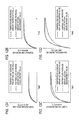
- FIG. 12A to FIG. 12D are graphs illustrating a relationship between an estimation value ( ⁇ ) of a temperature increase amount of a motor and a driving time (t), and a relationship between an actual temperature increase amount and a driving time (t).
- the load in the case of FIG. 12A is smallest
- the load in the case of FIG. 12B is the second smallest
- the load in the case of FIG. 12C is the third smallest
- the load in the case of FIG. 12D is largest.
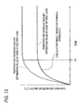
- FIG. 13 is a graph illustrating a relationship between the estimation value ( ⁇ ) of the temperature increase amount and the driving time (t) of the motor when the load on the motor is changed from a first load to a second load (>the first load) at a timing t 11 during the driving of the motor.
- the thermal time constant (T) is changed from a value for the first load to a value for the second load at the timing t 11 , the estimation value ( ⁇ ) of the temperature increase amount is rapidly increased at the timing t 11 . That is, even when the thermal time constant (T) according to the load is set, it is difficult to appropriately estimate the temperature of the motor in the course of gradually changing the temperature of the motor due to the change of the load.
- a threshold value for start determination of a restriction control for preventing the motor from breaking down has to be set low.
- the restriction control is a control for stopping the driving of the motor or slowing the driving rate of the motor during a predetermined period.
- a temperature of a brush of the motor is estimated. This is because the motor breaks down by breakdown of the brush when the brush is overheated.
- the estimation value of the temperature increase amount of the target member represented by the brush is calculated using the formula (Formula 1).
- the power loss (HTA) is “0 (zero)”. That is, in JP-A-2002-34283, a method of estimating a temperature change amount after stopping driving the motor is not disclosed.
- the heat radiation amount from the target member is changed depending on a temperature of a peripheral member (for example, yoke) or the like positioned around the target member, as well as the ambient temperature around the target member. For this reason, when the heat radiation amount from the target member is not estimated while also considering the temperature of the peripheral member positioned around the target member, the temperature of the target member after stopping the driving of the motor may not be estimated with high precision.
- a peripheral member for example, yoke
- An object of the invention is to provide a temperature estimating device and a temperature estimating method capable of improving precision in estimation of a temperature of apparatus constituent members constituting an electronic apparatus provided with a motor, after stopping the driving of the motor.
- Another object of the invention is to provide a temperature estimating device and a temperature estimating method capable of improving precision in estimation of a temperature of apparatus constituent members constituting an electronic apparatus provided with a motor.
- a temperature estimating device which estimates temperatures of target members of apparatus constituent members constituting an electronic apparatus provided with a motor for each predetermined period, the device including: a heat generation amount calculating unit for calculating heat generation amount of the motor on the basis of a difference between an input energy corresponding value corresponding to input energy input to the motor and an output energy corresponding value corresponding to output energy output from the motor; a heat radiation amount calculating unit for calculating heat radiation amounts from the target members on the basis of a difference between previous temperature estimation values of the target members and an ambient temperature around the electronic apparatus, and thermal coefficients representing thermal characteristics of the target members; and an estimation value calculating unit for acquiring temperature increase amounts of the target members on the basis of a difference between the heat generation amount and the heat radiation amounts calculated by the calculating unit, and calculating current temperature estimation values of the target members on the basis of the temperature increase amounts and the previous temperature estimation values of the target members.
- a temperature estimating device which estimates a temperature of a target member of apparatus constituent members constituting an electronic apparatus provided with a motor for each predetermined period, the device including: a provisional value estimating unit for estimating a temperature provisional value of the target member; a temperature acquiring unit for acquiring temperatures of the other apparatus constituent members other than the target member of the apparatus constituent members; and an estimation value setting unit for setting a temperature estimation value of the target member, wherein the estimation value setting unit set the current temperature provisional value of the target member estimated by the provisional value estimating unit to the current temperature estimation value of the target member at the time of driving the motor, and set the current temperature estimation value of the target member on the basis of the higher one of current temperatures of the particular apparatus constituent members of a temperature lower than the temperature provisional value of the target member during the driving of the motor and the current temperature provisional value of the target member, after stopping the driving of the motor.
- a temperature estimating method of estimating a temperature of a target member of apparatus constituent members constituting an electronic apparatus provided with a motor for each predetermined period including: a provisional value estimating step of estimating a temperature provisional value of the target member; a temperature acquiring step of acquiring temperatures of the other apparatus constituent members other than the target member of the apparatus constituent members; an estimation value setting in motor driving step of setting the temperature provisional value of the target member estimated in the provisional value estimating step to the current temperature estimation value of the target member at the time of driving the motor; and a estimation value setting in motor stopping step of setting the current temperature estimation value of the target member, on the basis of the higher one of the current temperature of the particular apparatus constituent member of a temperature lower than that of the temperature provisional value of the target member at the time of the driving of the motor and the current temperature provisional value of the target member, after stopping the driving of the motor.
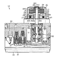
- FIG. 1 is a cross-sectional view illustrating a hydro-brake unit of an electronic apparatus provided with a temperature estimating device according to an embodiment of the invention.
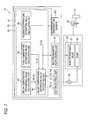
- FIG. 2 is a block diagram illustrating a schematic configuration of the hydro-brake unit.
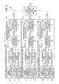
- FIG. 3 is a block diagram illustrating a function of a temperature estimating unit in detail.
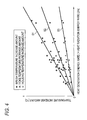
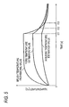
- FIG. 4 is a graph illustrating a heat generation energy rate and a temperature increase amount of an apparatus constituent member.
- FIG. 5 is a graph illustrating change of a temperature provisional value of a brush, a temperature estimation value of a yoke, and a temperature estimation value of a housing.
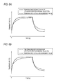
- FIG. 6A is a graph illustrating comparison between a temperature estimation value and a temperature actual-measurement value when a temperature provisional value is the temperature estimation value of the brush even after stopping the driving of the motor
- FIG. 6B is a graph illustrating a temperature estimation value and a temperature actual-measurement value when the temperature estimation value of the brush is set considering the temperature estimation values of the yoke and the housing after stopping the motor.
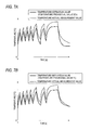
- FIG. 7A is a graph illustrating comparison between a temperature estimation value and a temperature actual-measurement value when a temperature provisional value is the temperature estimation value of the brush even after stopping the motor
- FIG. 7B is a graph illustrating comparison between a temperature estimation value and a temperature actual-measurement value when the temperature estimation value of the brush is set considering the temperature estimation values of the yoke and the housing after stopping the motor.
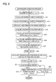
- FIG. 8 is a flowchart illustrating a temperature estimating process routine in the embodiment.
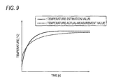
- FIG. 9 is a graph illustrating comparison between a temperature actual-measurement and a temperature estimation value of the brush of the motor.
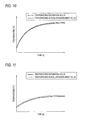
- FIG. 10 is a graph illustrating comparison between a temperature actual-measurement value and a temperature estimation value of the yoke of the motor.
- FIG. 11 is a graph illustrating comparison between a temperature actual-measurement value and a temperature estimation value of the housing.
- FIG. 12 ⁇ to FIG. 12D are graphs illustrating a relationship between an estimation value of a temperature increase amount of a motor calculated by the estimation method of the related art and a driving time of the motor, and a relationship between an actual-measurement value of a temperature increase amount and a driving time of the motor.
- FIG. 13 is a graph illustrating a relationship between an estimation value of a temperature increase amount of a motor and a driving time of the motor when the load on the motor is changed during the driving of the motor.
- an electronic apparatus of the embodiment is a hydro-brake unit 12 operating to adjust braking force against a wheel 11 mounted on a vehicle.
- the hydro-brake unit 12 includes a motor 20 , a substantially rectangular parallelepiped housing (apparatus constituent member) 30 in which the motor 20 is provided, an accommodation case 40 that is fixed at a position (in the embodiment, the opposite position) different from the installation position of the motor 20 in the housing 30 .
- the motor 20 of the embodiment is a direct-current motor provided with a brush.
- the motor 20 includes a substantially cylindrical bottomed yoke (apparatus constituent member) 21 opened to the housing 30 side, a plate-shaped end plate (apparatus constituent member) 22 closing the opening portion of the yoke 21 , and a rotor 24 disposed in an internal space 23 formed by the yoke 21 and the end plate 22 .
- the yoke 21 is formed of metal suppressing leakage of magnetic field generated in the internal space 23 to the outside.
- On an inner circumference face of the yoke 21 a plurality of magnets (apparatus constituent member) 25 are fixed at regular intervals along a circumferential direction.
- a bearing supporting portion 210 in which a bearing (apparatus constituent member) 26 is accommodated is integrally formed.
- the yoke 21 is fixed to the housing 30 by a plurality (in FIG. 1 , only two bolts are shown) of bolts 27 . That is, the motor 20 is mounted on the housing 30 through the yoke 21 .
- the end plate 22 is formed of synthetic resin. At the center of the end plate 22 , a through-hole 220 piercing in a plate thickness direction is formed.
- the end plate 22 is integrally provided with a brush holder 29 supporting a plurality of brushes (apparatus constituent members) 28 coming in contact with the rotor 24 .
- the brush holder 29 supports the brushes 28 through an urging member (apparatus constituent member) 29 A disposed on the outside in a diameter direction of the brushes 28 . That is, the brushes 28 are urged to the inside in the diameter direction by the urging member 29 A.
- An armature 240 of the rotor 24 is disposed to be opposed to the magnet 25 fixed to the yoke 21 .
- the armature 240 has a core (apparatus constituent member) 240 a and a plurality of armature coils (apparatus constituent member) 240 b wound on the core 240 a .
- An output shaft (apparatus constituent member) 241 of the rotor 24 is rotatably supported by the yoke 21 through the bearing 26 accommodated in the bearing supporting portion 210 .
- the armature 240 is fixed to the output shaft 241 .
- the output shaft 241 pierces the through-hole 220 formed in the end plate 22 and protrudes into the housing 30 .
- a commutator (apparatus constituent member) 242 of the rotor 24 is fixed to a part closer to the housing 30 than the armature 240 in the output shaft 241 .
- a plurality of commutator pieces 242 a electrically connected to an armature coil 240 b are disposed at regular intervals along the circumferential direction.
- the brushes 28 are disposed on the outside of the commutator 242 in the diameter direction.
- the brushes 28 come in contact with the commutator pieces 242 a of the commutator 242 .
- Electric current is supplied from the brushes 28 to the armature coil 240 b through the commutator pixels 242 a.
- the housing 30 is formed of a material (for example, metal such as aluminum) which is excellent from the viewpoint of weight and hardness.
- various electromagnetic valves 31 for adjusting braking force against the wheel 11 and a pump 32 as an example of a driving unit using the motor 20 as a driving source are accommodated.
- Liquid pressure in a wheel cylinder 33 provided in the wheel 11 of the vehicle is adjusted by operations of the various electromagnetic valves 31 and the pump 32 .
- the braking force according to the liquid pressure of the wheel cylinder 33 is applied to the wheel 11 .
- a circuit board 41 is accommodated. As shown in FIG. 2 , the circuit board 41 is provided with a control device 50 formed of a CPU, a ROM, and a RAM, a temperature sensor SE 1 for detecting a temperature of the circuit board 41 , and various driver circuits (not shown) for driving the electromagnetic valve 31 and the motor 20 .
- a control device 50 formed of a CPU, a ROM, and a RAM
- a temperature sensor SE 1 for detecting a temperature of the circuit board 41
- various driver circuits (not shown) for driving the electromagnetic valve 31 and the motor 20 .
- the control device 50 includes a motor control unit 51 that controls the motor 20 , an electromagnetic valve control unit 52 that controls various electromagnetic valves 31 , and a temperature estimating unit 53 as an example of a temperature estimating device, as functional units configured by software.
- the motor control unit 51 is electrically connected to a current sensor (not shown) for detecting a current value flowing in the motor 20 , and a′voltage sensor (not shown) for detecting a voltage value applied to the motor 20 .
- the motor control unit 51 acquires a current value Im flowing in the motor 20 and a voltage value Vm applied to the motor 20 on the basis of detection signals from the sensors.
- the motor control unit 51 outputs input information for specifying the acquired current value Im and voltage value Vm to the temperature estimating unit 53 .
- Temperature information for specifying a temperature estimation value Tb(n) of the brush 28 of the motor 20 calculated by the temperature estimating unit 53 is input to the motor control unit 51 .
- the motor control unit 51 determines whether or not the temperature estimation value Tb(n) specified by the input temperature information is equal to or larger than a preset temperature threshold value to determine whether or not the motor 20 is overheated.
- the motor control unit 51 performs a restriction control of continuing the control of the motor 20 when the temperature estimation value Tb(n) is smaller than the temperature threshold value, and restricting the driving of the motor 20 when the temperature estimation value Tb(n) is equal to or larger than the temperature threshold value.
- the restriction control for example, there may be a control of stopping the driving of the motor 20 during a predetermined period and a control of restricting the driving of the motor 20 at a rate equal to or higher than a regular rate.
- Temperature information for specifying the temperature estimation value Th(n) of the housing 30 calculated by the temperature estimating unit 53 is input to the electromagnetic valve control unit 52 .
- the electromagnetic valve control unit 52 sets a current value flowing in the electromagnetic valve 31 on the basis of the temperature estimation value Th(n) of the housing 30 specified by the input temperature information. That is, the current value flowing in the electromagnetic valve 31 is corrected by the temperature estimation value Th(n) of the housing 30 .
- the temperature estimating unit 53 estimates temperatures of a plurality of apparatus constituent members constituting the hydro-brake unit 12 . Specifically, the temperature estimating unit 53 estimates temperatures of the brush (target member) 28 of the motor 20 , and the yoke 21 and the housing 30 as an example of the other apparatus constituent members other than the brush 28 of the members constituting the motor 20 .
- the temperature estimating unit 53 includes a brush temperature provisional value calculating unit 60 as an example of a provisional value estimating unit, a yoke temperature estimation value calculating unit 70 as an example of a temperature acquiring unit, a housing temperature estimation value calculating unit 80 has an example of a temperature acquiring unit, and a brush temperature estimation value specifying unit 90 as an example of an estimation value setting unit, as functional units.
- Thermal capacity of the yoke 21 and the housing 30 is higher than the thermal capacity of the brush 28 . That is, in the embodiment, the yoke 21 and the housing 30 correspond to particular apparatus constituent members.
- the brush temperature provisional value calculating unit 60 calculates a temperature provisional value TZb(n) of the brush 28 considering a heat generation amount in the motor 20 and a heat radiation amount from the brush 28 .
- the brush temperature provisional value calculating unit 60 includes an input power calculating unit 61 , an output power calculating unit 62 , a heat generation energy calculating unit 63 , an ambient temperature calculating unit 64 , a heat radiation energy calculating unit 65 , a temperature increase amount calculating unit 66 , a temperature provisional value calculating unit 67 , and a temperature provisional value storing unit 68 , as functional units.
- the heat generation energy calculating unit 63 calculates a heat generation energy rate Ein that is a heat generation amount per unit time of the motor 20 .
- a unit of the heat generation energy rate Ein is “J/s (Joule/second)”.
- the heat generation amount per unit time of the motor 20 is called “heat generation energy rate” to clarify that the unit is a value obtained by dividing “J (Joule)” by “time (second)”.
- the ambient temperature calculating unit 64 detects a temperature in the accommodation case 40 on the basis of the detection signal from the temperature sensor SE 1 provided on the circuit board 41 , and estimates an ambient temperature Tf around the motor 20 on the basis of the temperature in the accommodation case 40 .
- the ambient temperature calculating unit 64 adds a preset offset value to the detected temperature in the accommodation case 40 such that the obtained value is the ambient temperature Tf.
- the offset value is a value corresponding to a temperature difference between the inside of the accommodation case 40 and the periphery of the motor 20 , and is set by a test or simulation.
- the ambient temperature calculating unit 64 outputs the calculated ambient temperature Tf to the heat radiation energy calculating unit 65 .
- the heat radiation energy calculating unit 65 calculates a heat radiation energy rate Eout (Eout_B) that is a heat radiation amount per unit time emitted from the motor 20 .
- a unit of the heat radiation energy rate Eout is “J/s (Joule/second)”.
- the heat radiation energy calculating unit 65 reads a temperature provisional value TZb(n ⁇ 1) of the brush 28 calculated at the previous timing from the temperature provisional value storing unit 68 .
- the heat radiation energy calculating unit 65 calculates the heat radiation energy rate Eout_B from the motor 20 by substituting the previous temperature provisional value TZb(n ⁇ 1) of the brush 28 , the ambient temperature Tf calculated by the ambient temperature calculating unit 64 , and the thermal coefficient A representing the thermal characteristics of the brush 28 for the following formula (Formula 3). Subsequently, the heat radiation energy calculating unit 65 outputs the calculated heat radiation energy rate Eout_B from the brush 28 to the temperature increase amount calculating unit 66 .
- the heat radiation energy calculating unit 65 serves as the heat radiation amount calculating unit for calculating the heat radiation energy rate Eout_B from the brush 28 on the basis of a difference between the previous temperature provisional value TZb(n ⁇ 1) of the brush 28 and the ambient temperature Tf, and the thermal coefficient A representing the thermal characteristics of the brush 28 .
- the heat radiation amount per unit time emitted from the target member is called “heat radiation energy rate” to clarify that the unit is a value obtained by dividing “J (Joule)” by “time (second)”.
- the thermal coefficients A representing the thermal characteristics of the apparatus constituent members such as the brush 28 , the yoke 21 , and the housing 30 will be described with reference to FIG. 4 .
- the thermal coefficient A is a coefficient representing a relationship (slopes of straight lines in FIG. 4 ) between the heat generation energy rate transmitted to the target member shown in FIG. 4 and the increase amount of the temperature increase amount of the target member.
- the graph shown in FIG. 4 is drawn as the following description.
- the temperature sensor is mounted on the apparatus constituent member, and the motor 20 is driven in a state where it is possible to measure the number of rotations N and the driving torque T of the motor 20 .
- a predetermined current value Im and a predetermined voltage value Vm are given to the motor 20 .
- the temperature of the apparatus constituent member is increased while the heat generation energy rate is higher than the heat radiation energy rate.
- the heat radiation energy rate is gradually raised, and the temperature increase rate of the apparatus constituent member is lowered.
- the temperature of the apparatus constituent member is not changed. Thereafter, by substituting the current value Im and the voltage value Vm given to the motor 20 for the formula (Formula 2), the input power Pin to the motor 20 is calculated, the output power Pout from the motor 20 is calculated on the basis of the formula (Formula 3), and the temperature of the apparatus constituent member is detected on the basis of the detection signal from the temperature sensor.
- the heat generation energy rate Ein of the motor 20 is calculated.
- the heat generation energy rate Ein of the motor 20 calculated as described above and the temperature increase amount of the apparatus constituent member after starting driving the motor 20 are acquired as the measurement result.
- a plurality of such measurement results are acquired by changing the input power Pin to the motor 20 .
- the plurality of acquired measurement results are plotted to draw the graph shown in FIG. 4 .
- the state where the temperature of the apparatus constituent member is not changed is a state where the heat generation energy rate Ein of the motor 20 and the heat radiation energy rate Eout from the apparatus constituent member are balanced.
- the heat generation energy rate Ein of the motor 20 based on the input power Pin and the output power Pout calculated in the state where the temperature of the apparatus constituent member is not changed may be the heat radiation energy rate Eout from the apparatus constituent member at this time point. That is, the graph shown in FIG. 4 is also a graph illustrating a relationship between the heat radiation energy rate Eout from the apparatus constituent member and the temperature increase amount of the apparatus constituent member.
- the temperature increase amount of the brush 28 that is an example of the apparatus constituent member gets larger as the heat generation energy rate Ein of the motor 20 gets higher.
- the temperature increase amount of the brush 28 and the heat generation energy rate Ein are in a proportional relationship. That is, the relationship between the temperature increase amount of the brush 28 and the heat generation energy rate Ein can be represented by a linear function.
- the linear function representing the relationship between the temperature increase amount and the heat generation energy rate Ein is represented by a first straight line S 1 .
- a slope representing the first straight line S 1 corresponds to the thermal coefficient A of the brush 28 .
- the temperature increase amount of the yoke 21 that is an example of the apparatus constituent member and the heat generation energy rate Ein of the motor 20 are in a proportional relationship. That is, the relationship between the temperature increase amount of the yoke 21 and the heat generation energy rate Ein can be represented by a linear function.
- the linear function representing the relationship between the temperature increase amount of the yoke 21 and the heat generation energy rate Ein is represented by a second straight line S 2 .
- a slope representing the second straight line S 2 corresponds to the thermal coefficient A of the yoke 21 .
- the temperature increase amount of the housing 30 that is an example of the apparatus constituent member and the heat generation energy rate Ein of the motor 20 are in a proportional relationship. That is, the relationship between the temperature increase amount of the housing 30 and the heat generation energy rate Ein can be represented by a linear function.
- the linear function representing the relationship between the temperature increase amount of the housing 30 and the heat generation energy rate Ein is represented by a third straight line S 3 .
- a slope representing the third straight line S 3 corresponds to the thermal coefficient A of the housing 30 .
- the thermal coefficient A of the brush 28 among the brush 28 , the yoke 21 , and the housing 30 is largest, the thermal coefficient A of the yoke 21 is second largest, and the thermal coefficient A of the housing 30 is smallest. This is determined according to the material constituting the apparatus constituent member, the volume of the apparatus constituent member, and the distance between the motor 20 and the apparatus constituent member (see FIG. 1 ).
- the thermal coefficients A of the members acquired as described above are prepared in advance.
- the temperature increase amount calculating unit 66 calculates the temperature increase rate ⁇ Tb(n) that is the estimation value of the temperature increase amount per unit time of the brush 28 . Specifically, the temperature increase amount calculating unit 66 calculates the temperature increase rate ⁇ Tb(n) of the brush 28 by substituting the heat generation energy rate Ein calculated in the heat generation energy calculating unit 63 and the heat radiation energy rate Eout (Eout_B) calculated in the heat radiation energy calculating unit 65 for the following formula (Formula 5). The temperature increase amount calculating unit 66 outputs the calculated temperature increase rate ⁇ Tb(n) to the temperature provisional value calculating unit 67 .
- a coefficient K for the brush 28 is a constant representing the temperature increase amount per “1 J (Joule)”, and is a proportional constant representing how the temperature of the brush 28 is changed by the input and output of the energy to and from the brush 28 .
- ⁇ Tb ( n ) ( E in ⁇ E out) ⁇ K
- the temperature provisional value calculating unit 67 calculates the current temperature provisional value TZb(n) of the brush. Specifically, the temperature provisional value calculating unit 67 calculates the current temperature provisional value TZb(n) of the brush 28 by substituting the temperature increase rate ⁇ Tb(n) calculated in the temperature increase amount calculating unit 66 and the previous temperature provisional value TZb(n ⁇ 1) of the brush 28 stored in the temperature provisional value storing unit 68 .
- a time is a time corresponding to a calculation interval of the temperature provisional value TZb.
- the “ ⁇ Tb(n) ⁇ ts” in the formula (Formula 6) corresponds to the estimation value of the temperature increase amount of the brush 28 at the time corresponding to a predetermined period.
- the provisional value calculating unit for calculating the current temperature provisional value TZb(n) of the brush 28 is configured by the temperature increase amount calculating unit 66 and the temperature provisional value calculating unit 67 .
- the temperature provisional value calculating unit 67 stores the calculated current temperature provisional value TZb(n) of the brush 28 in the temperature provisional value storing unit 68 , and outputs it to the brush temperature estimation value specifying unit 90 .
- TZb ( n ) TZb ( n ⁇ 1)+ ⁇ Tb ( n ) ⁇ ts Formula 6
- the yoke temperature estimation value calculating unit 70 calculates the temperature estimation value Ty(n) of the yoke 21 considering the heat generation amount in the motor 20 and the heat radiation amount from the yoke 21 .
- the yoke temperature estimation value calculating unit 70 includes an input power acquiring unit 71 , an output power acquiring unit 72 , a heat generation energy calculating unit 73 , an ambient temperature acquiring unit 74 , a heat radiation energy calculating unit 75 , a temperature increase amount calculating unit 76 , and a temperature estimation value calculating unit 77 , and a temperature estimation value storing unit 78 , as functional units.
- the input power acquiring unit 71 acquires the input power Pin calculated in the input power calculating unit 61 of the brush temperature provisional value calculating unit 60 , and outputs the input power Pin to the heat generation energy calculating unit 73 .
- the output power acquiring unit 72 acquires the output power Pout calculated in the output power calculating unit 62 of the brush temperature provisional value calculating unit 60 , and outputs the output power Pout to the heat generation energy calculating unit 73 .
- the ambient temperature acquiring unit 74 acquires the ambient temperature Tf calculated in the ambient temperature calculating unit 64 of the brush temperature provisional value calculating unit 60 , and outputs the ambient temperature Tf to the heat radiation energy calculating unit 75 .
- the heat radiation energy calculating unit 75 calculates the heat radiation energy rate Eout that is the heat radiation amount per unit time emitted from the yoke 21 . Specifically, the heat radiation energy calculating unit 75 reads the temperature estimation value Ty(n ⁇ 1) of the yoke 21 calculated at the previous timing from the temperature estimation value storing unit 78 . The heat radiation energy calculating unit 75 calculates the heat radiation energy rate Eout (Eout_Y) from the yoke 21 using the formula (Formula 4).
- the heat radiation energy calculating unit 75 calculates the heat radiation energy rate Eout_Y from the yoke 21 by substituting the previous temperature estimation value Ty(n ⁇ 1) of the yoke 21 for the previous temperature provisional value TZb(n ⁇ 1) of the brush 28 . Accordingly, in the embodiment, the heat radiation energy calculating unit 75 serves as the heat radiation amount calculating unit for calculating the heat radiation energy rate Eout_Y from the yoke 21 on the basis of the difference between the previous temperature estimation value Ty(n ⁇ 1) of the yoke (the other apparatus constituent member) 21 and the ambient temperature Tf, and the thermal coefficient A representing the thermal characteristics of the yoke 21 .
- the temperature increase amount calculating unit 76 calculates the temperature increase rate ⁇ Ty(n) that is the estimation value of the temperature increase amount per unit time of the yoke 21 . Specifically, the temperature increase amount calculating unit 76 calculates the temperature increase rate ⁇ Ty(n) of the yoke 21 by substituting the heat generation energy rate Ein calculated in the heat generation energy calculating unit 73 and the heat radiation energy rate Eout (Eout_Y) calculated in the heat radiation energy calculating unit 75 for the formula (Formula 5). In this case, as a coefficient K for the yoke 21 , a reciprocal of thermal capacity of the yoke 21 is set. The temperature increase amount calculating unit 76 outputs the calculated temperature increase rate ⁇ Ty(n) to the temperature estimation value calculating unit 77 .
- the temperature estimation value calculating unit 77 calculates the current temperature estimation value Ty(n) of the yoke 21 using the formula (Formula 6). In this case, the temperature estimation value calculating unit 77 substitutes the previous temperature estimation value Ty(n ⁇ 1) of the yoke 21 for the previous temperature provisional value TZb(n ⁇ 1) of the brush 28 , and substitutes the temperature increase rate ⁇ Ty(n) of the yoke 21 for the temperature increase rate ⁇ Tb(n) of the brush 28 . Accordingly, in the embodiment, the estimation value calculating unit for estimating the current temperature estimation value Ty(n) of the yoke (the other apparatus constituent member) 21 is configured by the temperature increase amount calculating unit 76 and the temperature estimation value calculating unit 77 . The temperature estimation value calculating unit 77 stores the calculated current temperature estimation value Ty(n) of the yoke 21 in the temperature estimation value storing unit 78 , and outputs it to the brush temperature estimation value specifying unit 90 .
- the housing temperature estimation value calculating unit 80 calculates the temperature estimation value Th(n) of the housing 30 considering the heat generation amount in the motor 20 and the heat radiation amount from the housing 30 .
- the housing temperature estimation value calculating unit 80 includes an input power acquiring unit 81 , an output power acquiring unit 82 , a heat generation energy calculating unit 83 , an ambient temperature acquiring unit 84 , a heat radiation energy calculating unit 85 , a temperature increase amount calculating unit 86 , and a temperature estimation value calculating unit 87 , and a temperature estimation value storing unit 88 , as functional units.
- the input power acquiring unit 81 acquires the input power Pin calculated in the input power calculating unit 61 of the brush temperature provisional value calculating unit 60 , and outputs the input power Pin to the heat generation energy calculating unit 83 .
- the output power acquiring unit 82 acquires the output power Pout calculated in the output power calculating unit 62 of the brush temperature provisional value calculating unit 60 , and outputs the output power Pout to the heat generation energy calculating unit 83 .
- the ambient temperature acquiring unit 84 acquires the ambient temperature Tf calculated in the ambient temperature calculating unit 64 of the brush temperature provisional value calculating unit 60 , and outputs the ambient temperature Tf to the heat radiation energy calculating unit 85 .
- the heat radiation energy calculating unit 85 calculates the heat radiation energy rate Eout (Eout_H) that is the heat radiation amount per unit time emitted from the housing 30 . Specifically, the heat radiation energy calculating unit 85 reads the temperature estimation value Th(n ⁇ 1) of the housing 30 calculated at the previous timing from the temperature estimation value storing unit 88 . The heat radiation energy calculating unit 85 calculates the heat radiation energy rate Eout_H from the housing 30 using the formula (Formula 4). In this case, the heat radiation energy calculating unit 85 calculates the heat radiation energy rate Eout_H from the housing 30 by substituting the previous temperature estimation value Th(n ⁇ 1) of the housing 30 for the previous temperature provisional value TZb(n ⁇ 1) of the brush 28 .
- the heat radiation energy calculating unit 85 serves as the heat radiation amount calculating unit for calculating the heat radiation energy rate Eout_H from the housing 30 on the basis of the difference between the previous temperature estimation value Th(n ⁇ 1) of the housing (the other apparatus constituent member) 30 and the ambient temperature Tf, and the thermal coefficient A representing the thermal characteristics of the housing 30 .
- the temperature increase amount calculating unit 86 calculates the temperature increase rate ⁇ Th(n) that is the estimation value of the temperature increase amount per unit time of the housing 30 . Specifically, the temperature increase amount calculating unit 86 calculates the temperature increase rate ⁇ Th(n) of the housing 30 by substituting the heat generation energy rate Ein calculated in the heat generation energy calculating unit 83 and the heat radiation energy rate Eout (Eout_H) calculated in the heat radiation energy calculating unit 85 . In this case, as a coefficient K for the housing 30 , a reciprocal of the thermal capacity of the housing 30 is set. The temperature increase amount calculating unit 86 outputs the calculated temperature increase rate ⁇ Th(n) to the temperature estimation value calculating unit 87 .
- the temperature estimation value calculating unit 87 calculates the current temperature estimation value Th(n) of the housing 30 using the formula (Formula 6). In this case, the temperature estimation value calculating unit 87 substitutes the previous temperature estimation value Th(n ⁇ 1) of the housing 30 for the previous temperature provisional value TZb(n ⁇ 1) of the brush 28 , and substitutes the temperature increase rate ⁇ Th(n) of the housing 30 for the temperature increase rate ⁇ Tb(n) of the brush 28 . Accordingly, in the embodiment, the estimation value calculating unit for estimating the current temperature estimation value Th(n) of the housing (the other apparatus constituent member) 30 is configured by the temperature increase amount calculating unit 86 and the temperature estimation value calculating unit 87 . The temperature estimation value calculating unit 87 stores the calculated current temperature estimation value Th(n) of the housing 30 in the temperature estimation value storing unit 88 , and outputs it to the brush temperature estimation value specifying unit 90 .
- the brush temperature estimation value specifying unit 90 specifies (sets) the current temperature estimation value Tb(n) of the brush 28 on the basis of the current temperature provisional value TZb(n) of the brush 28 , the current temperature estimation value Ty(n) of the yoke 21 , and the current temperature estimation value Th(n) of the housing 30 . Specifically, the brush temperature estimation value specifying unit 90 sets the current temperature provisional value TZb(n) of the brush 28 to the current temperature estimation value Tb(n) of the brush 28 at the time of driving the motor 20 .
- the brush temperature estimation value specifying unit 90 sets the largest value of the current temperature provisional value TZb(n) of the brush 28 , the current temperature estimation value Ty(n) of the yoke 21 , and the current temperature estimation value Th(n) of the housing 30 , to the current temperature estimation value Tb(n) of the brush 28 .
- the temperature provisional value TZb of the brush 28 is a heat generation source, with the lowest thermal capacity becomes a value larger than the temperature estimation values Ty and Th of the yoke 21 and the housing 30 .
- the temperature estimation value Ty of the yoke 21 with the second lowest thermal capacity becomes a value larger than the temperature estimation value Th of the housing 30 .
- the temperature provisional value TZb of the brush 28 and the temperature estimation values Ty and Th of the yoke 21 and the housing 30 become small.
- the temperature provisional value TZb of the brush 28 with the smallest thermal capacity becomes rapidly small.
- the temperature provisional value TZb of the brush 28 becomes smaller than the temperature estimation value Ty of the yoke 21 at the time point of elapsing the second timing t 12 , and becomes smaller than the temperature estimation value Th of the housing 30 at the time point of elapsing the third timing t 13 thereafter.
- the temperature of the brush 28 is not changed similarly to the temperature provisional value TZb of FIG. 5 . That is, the actual heat radiation energy rate from the brush 28 is determined by the temperature of the other member (in this case, the yoke 21 or the housing 30 ) positioned around the brush 28 , not only by the temperature around the brush 28 , that is, the ambient temperature Tf, particularly, at the time of stopping the motor 20 . Since the thermal capacity of the yoke 21 and the housing 30 is higher than the thermal capacity of the brush 28 , the temperatures of the yoke 21 and the housing 30 are not rapidly decreased similarly to the brush 28 .
- the temperature of the brush 28 is decreased substantially at the same rate as the temperature of the yoke 21 .
- the heat of the brush 28 and the yoke 21 is moved to the housing 30 with the temperature higher than those of the brush 28 and the yoke 21 .
- the temperatures of the brush 28 and the yoke 21 become substantially the same temperature as the temperature of the housing 30 , there is little heat movement between the brush 28 and yoke 21 and the housing 30 , and thus the temperatures of the brush 28 and the yoke 21 are not even lower than the temperature of the housing 30 . That is, the temperatures of the brush 28 and the yoke 21 are decreased substantially at the same rate as the temperature of the housing 30 .
- the temperature provisional value TZb is calculated on the basis of the heat generation energy rate Ein in the motor 20 and the heat radiation energy rate Eout_B calculated using the ambient temperature Tf. That is, the temperature provisional value TZb is a value calculated without adding the temperature of the other apparatus constituent member positioned around the brush 28 . For this reason, as shown in FIG. 6A , after stopping the driving of the motor 20 , there is a concern that the temperature provisional value TZb may be disparate from the actual temperature of the brush 28 .
- the temperature provisional value TZb is larger than the temperature estimation values Ty and Th of the yoke 21 and the housing 30 , and thus the temperature provisional value TZb becomes the temperature estimation value Tb of the brush 28 .
- the temperature provisional value TZb is smaller than the temperature estimation value Ty of the yoke 21 , and thus the temperature estimation value Ty of the yoke 21 becomes the temperature estimation value Tb of the brush 28 .
- the temperature estimation value Th of the housing 30 becomes the temperature estimation value Tb of the brush 28 .
- the temperature estimation value Tb of the brush 28 becomes a value close to the actual-measurement value of the temperature of the brush 28 as compared with the temperature provisional value TZb.
- FIG. 7A and FIG. 7B show that the temperature provisional value TZb of the brush 28 and the temperature estimation value Tb of the brush 28 are fluctuated when the driving and the stopping of the motor 20 are continuously repeated.
- the temperature estimation value Tb of the brush 28 set by the estimation method of the embodiment becomes a value closer to the actual-measurement value of the temperature of the brush 28 than the temperature provisional value TZb (see FIG. 7A ) of the brush 28 .
- the temperature estimating process routine is a process routine performed for each preset predetermined period. That predetermined period coincides with the time ts.
- the main heat generation source of the hydro-brake unit 12 is the motor 20 .
- the motor 20 When the motor 20 is driven, the heat generated on the basis of the driving is transmitted to the apparatus constituent members constituting the hydro-brake unit 12 .
- the temperatures of the apparatus constituent members are increased. That is, the temperature increase of the apparatus constituent members is a temperature increase based on the driving of the motor 20 .
- the temperature increase rates of the apparatus constituent members are substantially proportional to the driving rate of the motor 20 , that is, the heat generation energy rate Ein of the motor 20 .
- the current temperature increase rates of the apparatus constituent members are obtained using the heat generation energy rate Ein of the motor 20 .
- the temperature estimating unit 53 stores the current temperature provisional value TZb(n) of the brush 28 calculated in Step S 17 in the temperature provisional value storing unit 68 (Step S 18 ).
- the temperature estimating unit 53 calculates the current temperature estimation value Ty(n) of the yoke 21 and the current temperature estimation value Th(n) of the housing 30 using the formula (Formula 6) (Step S 19 ).
- Step S 19 corresponds to the temperature acquiring step.
- the temperature estimating unit 53 stores the current temperature estimation value Ty(n) of the yoke 21 calculated in Step S 19 in the temperature estimation value storing unit 78 , and stores the current temperature estimation value Th(n) of the housing 30 in the temperature estimation value storing unit 88 (Step S 20 ).
- the temperature estimating unit 53 determines whether or not the motor 20 is being driven (Step S 21 ).
- the temperature estimating unit 53 sets the current temperature provisional value TZb(n) of the brush 28 calculated in Step S 17 to the current temperature estimation value Tb(n) of the brush 28 (Step S 22 ). Thereafter, the temperature estimating unit 53 ends the temperature estimating process routine once.
- Step S 22 corresponds to the estimation value setting in motor driving step.
- Step S 21 when the motor 20 is stopped (Step S 21 : No), the temperature estimating unit 53 sets the higher one of the current temperature provisional value TZb(n) of the brush 28 calculated in Step S 17 , the current temperature estimation value Ty(n) of the yoke 21 calculated in Step S 19 , and the current temperature estimation value Th(n) of the housing 30 , to the current temperature estimation value Tb(n) of the brush 28 (Step S 23 ). Thereafter, the temperature estimating unit 53 ends the temperature estimating process routine once. Accordingly, in the embodiment, Step S 23 corresponds to the estimation value setting in motor stopping step.
- the temperature increase rate ⁇ Tm(n) of the target member is calculated for each predetermined period, and the temperature increase amount of the target member at the predetermined period is calculated on the basis of the temperature increase rate ⁇ Tm(n).
- the current temperature estimation value Tm(n) of the target member is calculated by adding the calculated temperature increase amount to the previous temperature estimation value Tm(n ⁇ 1) of the target member.
- the temperature increase rate ⁇ Tm is calculated on the basis of the heat generation energy rate Ein at the time point of the motor 20 that is the main heat generation source of the hydro-brake unit 12 and the heat radiation energy rate Eout at the time point from the target member. For this reason, for example, during the driving of the motor 20 , even when the driving torque T of the motor 20 fluctuates, the heat generation rate Ein is calculated on the basis of the current value Im flowing in the motor 20 and the voltage value Vm applied to the motor 20 at the time point. As a result, the heat generation energy rate Ein of the motor 20 is calculated with high precision even when the driving torque T fluctuates as compared with the case of the calculation using a value obtained by squaring the current value Im.
- the temperatures of the brush 28 and the yoke 21 of the motor 20 , and the housing 30 are appropriately estimated even when the driving condition such as load on the motor 20 is changed during the driving of the motor 20 as shown in FIG. 9 , FIG. 10 , and FIG. 11 .
- the heat generation energy rate Ein of the motor 20 is obtained by subtracting the output power Pout from the motor 20 from the input power Pin to the motor 20 .
- the heat radiation energy rate Eout from the target member is acquired by dividing the value obtained by the ambient temperature Tf from the previous temperature estimation value Tm(n ⁇ 1) of the target member by the thermal coefficient A representing the thermal characteristics of the target member.
- the reason why the difference between the previous temperature estimation value Tm(n ⁇ 1) of the target member and the ambient temperature Tf is used at the time of calculating the heat radiation energy rate Eout is because the heat radiation amount per unit time from the target member fluctuates by the magnitude of the difference. For this reason, it is possible to improve estimation precision of the heat radiation energy rate Eout from the target member by setting the thermal coefficient A to an appropriate value.
- the temperature increase rate ⁇ Tm(n) of the target member is acquired on the basis of the heat generation energy rate Ein of the motor 20 calculated as described above and the heat radiation energy rate Eout from the target member.
- the variation of the estimation precision of the temperature increase rate ⁇ Tm(n) caused by the magnitude of load or the fluctuation of load on the motor 20 is suppressed to be low. Accordingly, by improving the estimation precision of the current temperature estimation value Tm(n) of the target member, it is possible to improve the temperature estimation precision of the apparatus constituent members constituting the hydro-brake unit 12 .
- the heat generation energy rate Ein of the motor 20 As the method of calculating the heat generation energy rate Ein of the motor 20 , a method of multiplying the value obtained by squaring the current value Im flowing in the motor 20 by a predetermined proportional constant can be considered. In this method, the heat generation energy rate Ein of the motor 20 is calculated using the input (that is, the current value) to the motor 20 without using the output from the motor 20 . In this case, in a situation where the driving torque of the motor 20 fluctuates, there is a concern that variation may occur in estimation precision of the heat generation energy rate Ein. From this point, in the embodiment, the heat generation energy rate Ein is calculated using the input power Pin to the motor 20 and the output power Pout from the motor 20 .
- the heat generation energy rate Ein of the motor 20 is calculated using not only the input to the motor 20 but also the output from the motor 20 . Accordingly, even when the fluctuation occurs in the driving torque T of the motor 20 , the heat generation energy rate Ein of the motor 20 is estimated with high precision, and thus it is possible to improve the estimation precision of the target member.
- the hydro-brake unit 12 is not driven. Meanwhile, when the requirement braking force is more than the maximum value of the regenerative braking force, the hydro-brake unit 12 is driven to supplement the difference between the requirement braking force and the regenerative braking force.
- the driving torque T required for the motor 20 in this case fluctuates according to the magnitude of the difference between the requirement braking force and the regenerative braking force.
- the temperature of the target member of the apparatus constituent members of the hydro-brake unit 12 driven under such use environment is estimated by the temperature estimating method of the embodiment. In other words, it is possible to improve the estimation precision of the temperature of the apparatus constituent member of the hydro-brake unit 12 in which a driving aspect of the motor 20 fluctuates from time to time.
- the brush 28 is slid with respect to the rotor 24 , and thus the brush 28 easily becomes a high temperature.
- the motor 20 is also broken down. From this point, in the embodiment, the temperature of the brush 28 is estimated with high precision, and thus it is possible to start the restriction control of restricting the driving of the motor 20 at the proper timing before the brush 28 becomes too high temperature.
- the temperature sensor SE 1 is a sensor for detecting the temperature of the control device 50 provided on the circuit board 41 .
- the ambient temperature Tf is acquired using the temperature sensor SE 1 . For this reason, even when the temperature sensor for detecting the temperature around the motor 20 is not provided, it is possible to appropriately set the ambient temperature Tf, and further it is possible to improve the estimation precision of the heat radiation energy rate Eout of the target member.
- the temperature of the brush 28 is estimated on the basis of the temperature provisional value TZb(n) of the brush 28 after stopping the driving of the motor 20 , and is estimated on the basis of the temperature estimation values Ty(n) and Th(n) of the yoke 21 and the housing 30 smaller than the temperature provisional value TZb(n) of the brush 28 during the driving of the motor 20 . That is, the temperature estimation value Tb(n) of the brush 28 becomes the largest value of the temperature provisional value TZb(n) of the brush 28 , and the temperature estimation values Ty(n) and Th(n) of the yoke 21 and the housing 30 .
- the temperature of the brush 28 may be lower than the temperatures of the yoke 21 and the housing 30 with the thermal capacity higher than that of the brush 28 is low after stopping the driving of the motor 20 .
- the temperature estimation value Tb(n) of the brush 28 is acquired in addition to the temperature estimation values of the other apparatus constituent members (the yoke 21 and the housing 30 ) positioned around the brush 28 . Accordingly, after stopping the driving of the motor 20 , it is possible to improve the estimation precision of the temperature of the brush 28 that is one of the apparatus constituent members constituting the hydro-brake unit 12 with high precision.
- the housing 30 is a member with the higher thermal capacity of the plurality of apparatus constituent members constituting the hydro-brake unit 12 . For this reason, at the time of stopping the driving of the motor 20 , the temperature of the brush 28 is not lower than the temperature of the housing 30 . Accordingly, in the embodiment, the temperature estimation value Th of the housing 30 with the higher thermal capacity is acquired. At the time of stopping the driving of the motor 20 , the current temperature estimation value Tb(n) of the brush 28 is set considering the current temperature estimation value Th(n) of the housing 30 . For this reason, it is possible to improve the estimation precision of the temperature of the brush 28 .
- the heat generation energy rate Ein of the motor 20 is obtained by subtracting the output power Pout from the motor 20 from the input power Pin to the motor 20 .
- the heat radiation energy rate Eout_B from the brush 28 is acquired by dividing the value obtained by subtracting the ambient temperature Tf from the previous temperature provisional value TZb(n ⁇ 1) of the brush 28 by the thermal coefficient A representing the thermal characteristics of the brush 28 .
- the reason why the difference between the previous temperature provisional value TZb(n ⁇ 1) of the brush 28 and the ambient temperature Tf is used at the time of calculating the heat radiation energy rate Eout_B is because the heat radiation amount per unit time from the brush 28 fluctuates according to the largeness and smallness of the difference. For this reason, by setting the thermal coefficient A to a proper value, it is possible to improve the estimation precision of the heat radiation energy rate Eout_B from the brush 28 .
- the temperature increase rate ⁇ Tb(n) of the brush 28 is acquired on the basis of the heat generation energy rate Ein of the motor 20 calculated as described above and the heat radiation energy rate Eout_B from the brush 28 .
- the estimation precision of the current temperature provisional value TZb(n) of the brush 28 is improved.
- the calculated temperature provisional value TZb(n) becomes the temperature estimation value Tb(n) of the brush 28 . Accordingly, it is possible to improve the estimation precision of the temperature of the brush 28 at the time of driving the motor 20 .
- the heat generation energy rate Ein of the motor 20 is calculated using the input (that is, current value) to the motor 20 without using the output from the motor 20 .
- the heat generation energy rate Ein is calculated using the input power Pin to the motor 20 and the output power Pout from the motor 20 .
- the heat generation energy rate Ein is calculated using not only the input to the motor 20 but also the output from the motor 20 . Accordingly, even when the fluctuation occurs in the driving torque T of the motor 20 , the heat generation energy rate Ein of the motor 20 is estimated with high precision, and thus it is possible to improve the estimation precision of the brush 28 .
- the hydro-brake unit 12 is not driven. Meanwhile, when the requirement braking force is more than the maximum value of the regenerative braking force, the hydro-brake unit 12 is driven to supplement the difference between the requirement braking force and the regenerative braking force.
- the driving torque T required for the motor 20 in this case fluctuates according to the magnitude of the difference between the requirement braking force and the regenerative braking force.
- the temperature of the brush 28 constituting the hydro-brake unit 12 driven under such use environment is estimated by the temperature estimating method of the embodiment.
- the temperature estimating method of the embodiment it is possible to improve the estimation precision of the temperature of the brush 28 of the hydro-brake unit 12 in which a driving aspect of the motor 20 fluctuates from time to time.
- the brush 28 is slid with respect to the rotor 24 , and thus the brush 28 easily becomes a high temperature.
- the motor 20 is also broken down. From this point, in the embodiment, the temperature of the brush 28 is estimated with high precision, and thus it is possible to start the restriction control of restricting the driving of the motor 20 at the proper timing before the brush 28 becomes too high temperature.
- the temperatures estimation values Ty(n) and Th(n) of the yoke 21 and the housing 30 are calculated by the same method as the method of calculating the temperature provisional value TZb(n) of the brush 28 . That is, it is possible to estimate the temperature estimation values Ty(n) and the Th(n) of the yoke 21 and the housing 30 without using a dedicated temperature sensor.
- the temperature sensor SE 1 is a sensor for detecting the temperature of the control device 50 provided on the circuit board 41 .
- the ambient temperature Tf is acquired using the temperature sensor SE 1 . For this reason, even when the temperature sensor for detecting the temperature around the motor 20 is not provided, it is possible to appropriately set the ambient temperature Tf, and further it is possible to improve the estimation precision of the heat radiation energy rates Eout_B, Eout_Y, and Eout_H of the brush 28 , the yoke 21 , and the housing 30 .
- the embodiment may be modified to the other embodiments described as follows.
- the ambient temperature calculating unit 534 may detect the ambient temperature Tf around the hydro-brake unit 12 on the basis of the detection signal from the temperature sensor.
- the ambient temperature Tf may be a temperature acquired just after an ignition switch of the vehicle is turned on.
- the ambient temperature Tf in the case may be a preset temperature.
- the temperature estimating process routine may continue even when the ignition switch of the vehicle is turned off. In this case, when the temperature estimation value Tm(n) of the target member coincides with the ambient temperature Tf, the temperature estimating process routine may be ended.
- a sensor for example, a rotary encoder for detecting the number of rotations may be provided around the output shaft 241 of the motor 20 , and the number of rotations N of the motor 20 may be detected on the basis of the detection signal from the sensor.
- the driving torque T of the motor 20 may be detected using the output from the sensor for detecting the number of rotations.
- the motor 20 may be provided with a torque detecting sensor, and the driving torque T of the motor 20 may be detected on the basis of the detection signal from the sensor.
- temperatures of the other apparatus constituent members other than the brush 28 , the yoke 21 , and the housing 30 may be estimated.
- the temperature of the armature coil 240 b of the motor 20 may be estimated.
- the motor mounted on the electronic apparatus may be a brushless motor. That is, the motor may be a stepping motor and a voice coil motor.
- the electronic apparatus of the invention may be embodied by the other apparatus other than the hydro-brake unit if it is an electronic apparatus of a vehicle.
- the electronic apparatus may be embodied by an electric power steering device, and may be embodied by an electric parking brake device.
- the electronic apparatus of the invention may be embodied by a home electronic apparatus such as a washing machine and a dish washer.
- a home electronic apparatus such as a washing machine and a dish washer.
- the electronic apparatus ( 12 ) includes a housing ( 30 ) in which the motor ( 20 ) is provided through the yoke ( 21 ), an accommodation case ( 40 ) that is provided in the housing ( 30 ), and a circuit board ( 41 ) that is disposed in the accommodation case ( 40 ), as the apparatus constituent members, the circuit board ( 41 ) includes a control device ( 50 ) that controls the electronic apparatus ( 12 ), and a temperature sensor (SE 1 ) that detects a temperature in the accommodation case ( 41 ), and the temperature estimating device further includes ambient temperature acquiring unit ( 534 and S 14 ) for acquiring an ambient temperature (Tf) around the electronic apparatus ( 12 ) on the basis of the temperature in the accommodation case ( 41 ) calculated using the temperature sensor (SE 1 ).
- a method of estimating temperatures of the other apparatus constituent members other than the brush 28 may be an arbitrary method other than the method described above.
- the value obtained by squaring the current value Im flowing in the motor 20 may be multiplied by a predetermined proportional constant to obtain the heat generation energy rate Ein of the motor 20
- the temperature estimation values Ty(n) and Th(n) of the yoke 21 and the housing 30 may be calculated using the heat generation energy rate Ein.
- a temperature sensor for detecting a temperature of the other apparatus constituent member other than the brush 28 may be provided, and the temperature of the other apparatus constituent member may be detected on the basis of the detection signal from the sensor. In this case, after stopping the driving of the motor 20 , the temperature of the brush 28 may be estimated using the detected temperature of the other apparatus constituent member.
- the temperature estimation value Ty(n) of the yoke 21 may not be acquired.
- the temperature estimation value Tb(n) of the brush 28 is set on the basis of the maximum value of the temperature provisional value TZb(n) of the brush 28 and the temperature estimation value Th(n) of the housing 30 .
- the temperature estimation value of the other apparatus constituent member (for example, the end plate 22 ) other than the yoke 21 and the housing 30 may be acquired.
- the apparatus constituent member from which the temperature is acquired be a member with higher thermal capacity than that of the brush 28 that is the target member.
- the temperature estimation value Tb(n) of the brush 28 is set also using the temperature estimation value of the end plate 22 .
- the target member may be the other apparatus constituent member (for example, the armature coil 240 b ) other than the brush 28 .
- the target member be a member other than a member (in this case, the housing 30 ) with the higher thermal capacity of the apparatus constituent members constituting the hydro-brake unit 12 .
- the temperature estimation value Ty(n) of the yoke 21 may be the largest value of the temperature estimation value Ty(n) and the temperature estimation value Th(n) of the housing 30 .
- the method of estimating the temperature of the target member may be an arbitrary method other than the method described above.
- the value obtained by squaring the current value Im flowing in the motor 20 may be multiplied by a predetermined proportional constant to obtain the heat generation energy rate Ein of the motor 20 , and the temperature provisional value of the target member may be calculated using the heat generation energy rate Ein.
- the value obtained by multiplying the temperature by a predetermined coefficient may be the temperature estimation value Tb(n) of the brush 28 .
- the value obtained by multiplying the temperature estimation value Ty(n) by a predetermined first coefficient (a value larger than 1, for example, “1.1”) may be the temperature estimation value Tb(n) of the brush 28 .
- the value obtained by multiplying the temperature estimation value Th(n) by a predetermined second coefficient (a value larger than 1, for example, “1.2”) may be the temperature estimation value Tb(n) of the brush 28 .
- the second coefficient be larger than the first coefficient.
- the ambient temperature calculating unit 64 may detect the ambient temperature Tf around the hydro-brake unit 12 on the basis of the detection signal from the temperature sensor.
- the ambient temperature Tf may be a temperature acquired just after an ignition switch of the vehicle is turned on.
- the ambient temperature Tf in the case may be a preset temperature.
- the temperature estimating process routine may continue even when the ignition switch of the vehicle is turned off. In this case, when the temperature estimation value Tb(n) of the brush 28 coincides with the ambient temperature Tf, the temperature estimating process routine may be ended.
- a sensor for example, a rotary encoder for detecting the number of rotations may be provided around the output shaft 241 of the motor 20 , and the number of rotations N of the motor 20 may be detected on the basis of the detection signal from the sensor.
- the driving torque T of the motor 20 may be detected using the output from the sensor for detecting the number of rotations.
- the motor 20 may be provided with a torque detecting sensor, and the driving torque T of the motor 20 may be detected on the basis of the detection signal from the sensor.
- the motor mounted on the electronic apparatus may be a brushless motor. That is, the motor may be a stepping motor and a voice coil motor.
- the electronic apparatus of the invention may be embodied by the other apparatus other than the hydro-brake unit if it is an electronic apparatus of a vehicle.
- the electronic apparatus may be embodied by an electric power steering device, and may be embodied by an electric parking brake device.
- the electronic apparatus of the invention may be embodied by a home electronic apparatus such as a washing machine and a dish washer.
- a home electronic apparatus such as a washing machine and a dish washer.
- the temperature acquiring unit ( 70 and S 19 ) acquire the temperature (Ty(n)) of the yoke ( 21 ) of the motor ( 20 ) as the temperature of the member of the other apparatus constituent member.
- the electronic apparatus ( 12 ) further includes a housing ( 30 ) in which a driving unit ( 32 ) using the motor ( 20 ) as a driving source is accommodated, the motor ( 20 ) is provided in the housing ( 30 ) mounted through the yoke ( 21 ), and the temperature acquiring unit ( 80 and S 19 ) acquire the temperature (Th(n)) of the housing ( 30 ) as the temperature of the member of the other apparatus constituent member.
- a control target such as an electromagnetic valve controlled by a control device or the like is accommodated. Operation characteristics of the control target are slightly changed according to the temperature of itself. For this reason, when it is possible to accurately estimate the temperature of the control target, it is possible to more appropriately control the control target. For this reason, when it is possible to accurately estimate the temperature of the housing, it is possible to more appropriately operate the control target by performing the control of the control target based on the estimation result. From this point, in the invention, the temperature of the housing is estimated with high precision. As a result, it is possible to more appropriately operate the electromagnetic valve by performing the control of the control target based on the temperature estimation value of the housing.
- the electronic apparatus ( 12 ) adjusts braking force against the wheel ( 11 ) mounted on the vehicle, and an electromagnetic valve ( 31 ) is provided in the housing ( 30 ) to adjust the braking force against the wheel ( 11 ).
- the temperature of the housing is estimated with high precision, the control of the electromagnetic valve based on the estimation result is performed, and thus it is possible to more appropriately operate the electromagnetic valve. That is, it is possible to appropriately adjust the braking force against the wheel.
Landscapes
- Physics & Mathematics (AREA)
- General Physics & Mathematics (AREA)
- Control Of Electric Motors In General (AREA)
- Control Of Direct Current Motors (AREA)
Abstract
Description
Pin=Vm·Im Formula 2
Pout=0.14796·N·T Formula 3
ΔTb(n)=(Ein−Eout)·K Formula 5
TZb(n)=TZb(n−1)+ΔTb(n)·ts Formula 6
Claims (12)
Applications Claiming Priority (4)
| Application Number | Priority Date | Filing Date | Title |
|---|---|---|---|
| JP2011073135A JP5674524B2 (en) | 2011-03-29 | 2011-03-29 | Temperature estimation apparatus and temperature estimation method |
| JP2011073136A JP5739708B2 (en) | 2011-03-29 | 2011-03-29 | Temperature estimation apparatus and temperature estimation method |
| JP2011-073136 | 2011-03-29 | ||
| JP2011-073135 | 2011-03-29 |
Publications (2)
| Publication Number | Publication Date |
|---|---|
| US20120249039A1 US20120249039A1 (en) | 2012-10-04 |
| US8975851B2 true US8975851B2 (en) | 2015-03-10 |
Family
ID=46926315
Family Applications (1)
| Application Number | Title | Priority Date | Filing Date |
|---|---|---|---|
| US13/433,953 Expired - Fee Related US8975851B2 (en) | 2011-03-29 | 2012-03-29 | Temperature estimating device and temperature estimating method |
Country Status (2)
| Country | Link |
|---|---|
| US (1) | US8975851B2 (en) |
| CN (1) | CN102735358B (en) |
Cited By (3)
| Publication number | Priority date | Publication date | Assignee | Title |
|---|---|---|---|---|
| US20140112369A1 (en) * | 2012-10-18 | 2014-04-24 | Fanuc Corporation | Temperature estimation apparatus for estimating temperature of motor |
| US20140161152A1 (en) * | 2011-07-27 | 2014-06-12 | Siemens Aktiengesellschaft | Thermal monitoring of a converter |
| TWI617107B (en) * | 2016-01-22 | 2018-03-01 | Hitachi Industrial Equipment Systems Co Ltd | Motor control unit |
Families Citing this family (12)
| Publication number | Priority date | Publication date | Assignee | Title |
|---|---|---|---|---|
| US20140163765A1 (en) * | 2012-12-07 | 2014-06-12 | Qualcomm Incorporated | System and method for estimating ambient temperaure from a portable computing device |
| JP5667242B2 (en) | 2013-06-10 | 2015-02-12 | ファナック株式会社 | Temperature estimation device for estimating temperature of power semiconductor chip and motor control device including the same |
| WO2015118678A1 (en) * | 2014-02-10 | 2015-08-13 | 株式会社日立産機システム | Motor power conversion device |
| JP5877856B2 (en) * | 2014-03-03 | 2016-03-08 | ファナック株式会社 | Numerical control device with heat dissipation characteristic estimation unit |
| CN104393817A (en) * | 2014-10-30 | 2015-03-04 | 广东美的制冷设备有限公司 | Motor driving method and device, air-conditioner and electric appliance |
| CN105292099A (en) * | 2015-10-30 | 2016-02-03 | 克诺尔车辆设备(苏州)有限公司 | Brake disc temperature control method and control system and vehicle braking system |
| DE102016117529A1 (en) * | 2016-06-02 | 2017-12-07 | Trafag Ag | Torque sensor assembly and method for torque measurement and torque control device and electric drive |
| CN106998170B (en) * | 2016-08-31 | 2019-08-20 | 南京奥联汽车电子技术有限公司 | Direct current generator method for excessive heating protection and implementation step based on feedback current |
| JP6370971B1 (en) | 2017-03-03 | 2018-08-08 | ファナック株式会社 | Life evaluation device and robot system |
| CN108471271B (en) * | 2018-04-16 | 2021-03-23 | 成都极米科技股份有限公司 | Projector sliding door motor control method and control device |
| CN110874079B (en) * | 2018-08-30 | 2023-07-14 | Abb瑞士股份有限公司 | Method and system for monitoring the condition of an electric drive |
| TWI679831B (en) * | 2019-04-19 | 2019-12-11 | 黃思倫 | Motor / motor-generator with multiple permanent magnet pairs inward and outward rotor |
Citations (15)
| Publication number | Priority date | Publication date | Assignee | Title |
|---|---|---|---|---|
| JPH1189083A (en) | 1997-09-10 | 1999-03-30 | Toyoda Mach Works Ltd | Motor controller |
| US5949488A (en) * | 1995-12-28 | 1999-09-07 | Daewoo Electronics Co., Ltd. | Video signal encoding system controller |
| JP2002034283A (en) | 2000-07-18 | 2002-01-31 | Unisia Jecs Corp | Temperature estimating device of electric motor |
| JP2003014552A (en) | 2001-06-29 | 2003-01-15 | Nissan Motor Co Ltd | Temperature detector |
| JP2003284375A (en) | 2002-03-20 | 2003-10-03 | Toyota Motor Corp | Motor temperature estimating apparatus and motor control device |
| JP2006112333A (en) | 2004-10-15 | 2006-04-27 | Toyota Motor Corp | Electric air pump control device for secondary air supply device |
| JP2007028887A (en) | 2005-06-07 | 2007-02-01 | Honeywell Internatl Inc | Motor temperature control using estimated motor temperature based on motor power dissipation |
| US20070153433A1 (en) | 2005-06-07 | 2007-07-05 | Honeywell International, Inc. | Motor temperature control using estimated motor temperature based on motor power dissipation |
| US20070163381A1 (en) * | 2006-01-17 | 2007-07-19 | Denso Corporation | Starter |
| US20080024080A1 (en) * | 2006-07-26 | 2008-01-31 | Honda Motor Co., Ltd. | Motor protection system |
| JP2008109816A (en) | 2006-10-27 | 2008-05-08 | Nissan Motor Co Ltd | Temperature protecting device for motor, and temperature protection method of motor |
| US20080147272A1 (en) * | 2006-12-18 | 2008-06-19 | Masahiko Kamiya | Motion control device for vehicle |
| JP2009196627A (en) | 2008-01-24 | 2009-09-03 | Advics Co Ltd | Brake hydraulic pressure control device |
| US20100264670A1 (en) * | 2009-04-17 | 2010-10-21 | Denso Corporation | Starter for starting internal combustion engine |
| US8487563B2 (en) * | 2009-11-27 | 2013-07-16 | Denso Corporation | Drive motor control apparatus for vehicle, motor control system, method for correcting rotation angle of motor, program for performing the same, rotation detecting apparatus |
Family Cites Families (2)
| Publication number | Priority date | Publication date | Assignee | Title |
|---|---|---|---|---|
| JPS6365318A (en) * | 1986-09-05 | 1988-03-23 | Daikin Ind Ltd | Warmth detecting element |
| JP4658818B2 (en) * | 2006-01-19 | 2011-03-23 | 株式会社山武 | Temperature estimation method and apparatus |
-
2012
- 2012-03-29 CN CN201210089653.2A patent/CN102735358B/en not_active Expired - Fee Related
- 2012-03-29 US US13/433,953 patent/US8975851B2/en not_active Expired - Fee Related
Patent Citations (16)
| Publication number | Priority date | Publication date | Assignee | Title |
|---|---|---|---|---|
| US5949488A (en) * | 1995-12-28 | 1999-09-07 | Daewoo Electronics Co., Ltd. | Video signal encoding system controller |
| JPH1189083A (en) | 1997-09-10 | 1999-03-30 | Toyoda Mach Works Ltd | Motor controller |
| JP2002034283A (en) | 2000-07-18 | 2002-01-31 | Unisia Jecs Corp | Temperature estimating device of electric motor |
| JP2003014552A (en) | 2001-06-29 | 2003-01-15 | Nissan Motor Co Ltd | Temperature detector |
| JP2003284375A (en) | 2002-03-20 | 2003-10-03 | Toyota Motor Corp | Motor temperature estimating apparatus and motor control device |
| US20050242760A1 (en) | 2002-03-20 | 2005-11-03 | Toyota Jidosha Kabushiki Kaisha | Motor temperature estimator and motor controller |
| JP2006112333A (en) | 2004-10-15 | 2006-04-27 | Toyota Motor Corp | Electric air pump control device for secondary air supply device |
| US20070153433A1 (en) | 2005-06-07 | 2007-07-05 | Honeywell International, Inc. | Motor temperature control using estimated motor temperature based on motor power dissipation |
| JP2007028887A (en) | 2005-06-07 | 2007-02-01 | Honeywell Internatl Inc | Motor temperature control using estimated motor temperature based on motor power dissipation |
| US20070163381A1 (en) * | 2006-01-17 | 2007-07-19 | Denso Corporation | Starter |
| US20080024080A1 (en) * | 2006-07-26 | 2008-01-31 | Honda Motor Co., Ltd. | Motor protection system |
| JP2008109816A (en) | 2006-10-27 | 2008-05-08 | Nissan Motor Co Ltd | Temperature protecting device for motor, and temperature protection method of motor |
| US20080147272A1 (en) * | 2006-12-18 | 2008-06-19 | Masahiko Kamiya | Motion control device for vehicle |
| JP2009196627A (en) | 2008-01-24 | 2009-09-03 | Advics Co Ltd | Brake hydraulic pressure control device |
| US20100264670A1 (en) * | 2009-04-17 | 2010-10-21 | Denso Corporation | Starter for starting internal combustion engine |
| US8487563B2 (en) * | 2009-11-27 | 2013-07-16 | Denso Corporation | Drive motor control apparatus for vehicle, motor control system, method for correcting rotation angle of motor, program for performing the same, rotation detecting apparatus |
Non-Patent Citations (2)
| Title |
|---|
| Japanese Notification of Reasons for Refusal dated Jul. 1, 2014 issued in the corresponding Japanese Patent Application No. 2011-073136 and English language translation (6 pages). |
| Japanese Notification of Reasons for Refusal dated Sep. 9, 2014 issued in the corresponding Japanese Patent Application No. 2011-073135 and English language translation (7 pages). |
Cited By (5)
| Publication number | Priority date | Publication date | Assignee | Title |
|---|---|---|---|---|
| US20140161152A1 (en) * | 2011-07-27 | 2014-06-12 | Siemens Aktiengesellschaft | Thermal monitoring of a converter |
| US10101377B2 (en) * | 2011-07-27 | 2018-10-16 | Siemens Aktiengesellschaft | Thermal monitoring of a converter |
| US20140112369A1 (en) * | 2012-10-18 | 2014-04-24 | Fanuc Corporation | Temperature estimation apparatus for estimating temperature of motor |
| US9091600B2 (en) * | 2012-10-18 | 2015-07-28 | Fanuc Corporation | Temperature estimation apparatus for estimating temperature of motor |
| TWI617107B (en) * | 2016-01-22 | 2018-03-01 | Hitachi Industrial Equipment Systems Co Ltd | Motor control unit |
Also Published As
| Publication number | Publication date |
|---|---|
| CN102735358A (en) | 2012-10-17 |
| CN102735358B (en) | 2016-03-30 |
| US20120249039A1 (en) | 2012-10-04 |
Similar Documents
| Publication | Publication Date | Title |
|---|---|---|
| US8975851B2 (en) | Temperature estimating device and temperature estimating method | |
| JP5674524B2 (en) | Temperature estimation apparatus and temperature estimation method | |
| US9628017B2 (en) | Motor control device, and motor control method | |
| JP4215025B2 (en) | Vehicle power generation control device | |
| RU2419959C1 (en) | Motor control device and method | |
| JP5811755B2 (en) | Motor temperature detection device and driving force control device | |
| EP3041126B1 (en) | Sensor abnormality determining apparatus | |
| US9242576B1 (en) | Method and apparatus for controlling an electric machine | |
| KR101664039B1 (en) | System for estimating temperature of motor and method thereof | |
| CN112970192B (en) | Method for monitoring continuous state of motor | |
| JP5760865B2 (en) | Vehicle motor temperature detection device | |
| EP3503377B1 (en) | Overheating detection device | |
| WO2013171843A1 (en) | Field winding rotating electrical machine and method for controlling field current of a field winding rotating electrical machine | |
| JP6502172B2 (en) | Electric brake device | |
| JP2009131069A (en) | Motor control unit | |
| EP4079564B1 (en) | Control apparatus for electric motor and vehicle | |
| JP5739708B2 (en) | Temperature estimation apparatus and temperature estimation method | |
| CN109313086B (en) | Coil temperature estimation method | |
| JP7231199B2 (en) | Method and system for crank starting an internal combustion engine | |
| EP2842224A2 (en) | Electric motor control | |
| JP6090364B2 (en) | Control device for vehicle equipped with permanent magnet type synchronous motor and method for setting upper limit temperature of permanent magnet type synchronous motor | |
| JP2019002292A (en) | Electric pump system | |
| KR102323684B1 (en) | Method for controlling in-wheel motor system and apparatus thereof | |
| KR20160013038A (en) | Method for conveying a metered hydraulic volume in a vehicle braking system by means of an electrically driven motor pump assembly and vehicle braking system | |
| CN117922217A (en) | Control method and system of electromagnetic active suspension and vehicle |
Legal Events
| Date | Code | Title | Description |
|---|---|---|---|
| AS | Assignment |
Owner name: DENSO CORPORATION, JAPAN Free format text: ASSIGNMENT OF ASSIGNORS INTEREST;ASSIGNORS:USAMI, TADAYOSHI;YOSHIOKA, NOBUHIKO;REEL/FRAME:027955/0324 Effective date: 20120326 Owner name: ADVICS CO., LTD., JAPAN Free format text: ASSIGNMENT OF ASSIGNORS INTEREST;ASSIGNORS:USAMI, TADAYOSHI;YOSHIOKA, NOBUHIKO;REEL/FRAME:027955/0324 Effective date: 20120326 |
|
| STCF | Information on status: patent grant |
Free format text: PATENTED CASE |
|
| AS | Assignment |
Owner name: ADVICS CO., LTD., JAPAN Free format text: ASSIGNMENT OF ASSIGNORS INTEREST;ASSIGNOR:DENSO CORPORATION;REEL/FRAME:038489/0180 Effective date: 20160417 |
|
| MAFP | Maintenance fee payment |
Free format text: PAYMENT OF MAINTENANCE FEE, 4TH YEAR, LARGE ENTITY (ORIGINAL EVENT CODE: M1551); ENTITY STATUS OF PATENT OWNER: LARGE ENTITY Year of fee payment: 4 |
|
| FEPP | Fee payment procedure |
Free format text: MAINTENANCE FEE REMINDER MAILED (ORIGINAL EVENT CODE: REM.); ENTITY STATUS OF PATENT OWNER: LARGE ENTITY |
|
| LAPS | Lapse for failure to pay maintenance fees |
Free format text: PATENT EXPIRED FOR FAILURE TO PAY MAINTENANCE FEES (ORIGINAL EVENT CODE: EXP.); ENTITY STATUS OF PATENT OWNER: LARGE ENTITY |
|
| STCH | Information on status: patent discontinuation |
Free format text: PATENT EXPIRED DUE TO NONPAYMENT OF MAINTENANCE FEES UNDER 37 CFR 1.362 |
|
| FP | Lapsed due to failure to pay maintenance fee |
Effective date: 20230310 |