EP1487084A1 - Permanent magnet type motor and compressor comprising it - Google Patents
Permanent magnet type motor and compressor comprising it Download PDFInfo
- Publication number
- EP1487084A1 EP1487084A1 EP03707160A EP03707160A EP1487084A1 EP 1487084 A1 EP1487084 A1 EP 1487084A1 EP 03707160 A EP03707160 A EP 03707160A EP 03707160 A EP03707160 A EP 03707160A EP 1487084 A1 EP1487084 A1 EP 1487084A1
- Authority
- EP
- European Patent Office
- Prior art keywords
- magnet
- central
- insertion portion
- magnetic flux
- magnets
- Prior art date
- Legal status (The legal status is an assumption and is not a legal conclusion. Google has not performed a legal analysis and makes no representation as to the accuracy of the status listed.)
- Granted
Links
Images



Classifications
-
- H—ELECTRICITY
- H02—GENERATION; CONVERSION OR DISTRIBUTION OF ELECTRIC POWER
- H02K—DYNAMO-ELECTRIC MACHINES
- H02K1/00—Details of the magnetic circuit
- H02K1/06—Details of the magnetic circuit characterised by the shape, form or construction
- H02K1/22—Rotating parts of the magnetic circuit
- H02K1/27—Rotor cores with permanent magnets
- H02K1/2706—Inner rotors
- H02K1/272—Inner rotors the magnetisation axis of the magnets being perpendicular to the rotor axis
- H02K1/274—Inner rotors the magnetisation axis of the magnets being perpendicular to the rotor axis the rotor consisting of two or more circumferentially positioned magnets
- H02K1/2753—Inner rotors the magnetisation axis of the magnets being perpendicular to the rotor axis the rotor consisting of two or more circumferentially positioned magnets the rotor consisting of magnets or groups of magnets arranged with alternating polarity
- H02K1/276—Magnets embedded in the magnetic core, e.g. interior permanent magnets [IPM]
-
- H—ELECTRICITY
- H02—GENERATION; CONVERSION OR DISTRIBUTION OF ELECTRIC POWER
- H02K—DYNAMO-ELECTRIC MACHINES
- H02K1/00—Details of the magnetic circuit
- H02K1/06—Details of the magnetic circuit characterised by the shape, form or construction
- H02K1/22—Rotating parts of the magnetic circuit
- H02K1/27—Rotor cores with permanent magnets
-
- H—ELECTRICITY
- H02—GENERATION; CONVERSION OR DISTRIBUTION OF ELECTRIC POWER
- H02K—DYNAMO-ELECTRIC MACHINES
- H02K1/00—Details of the magnetic circuit
- H02K1/06—Details of the magnetic circuit characterised by the shape, form or construction
- H02K1/22—Rotating parts of the magnetic circuit
- H02K1/27—Rotor cores with permanent magnets
- H02K1/2706—Inner rotors
- H02K1/272—Inner rotors the magnetisation axis of the magnets being perpendicular to the rotor axis
- H02K1/274—Inner rotors the magnetisation axis of the magnets being perpendicular to the rotor axis the rotor consisting of two or more circumferentially positioned magnets
- H02K1/2753—Inner rotors the magnetisation axis of the magnets being perpendicular to the rotor axis the rotor consisting of two or more circumferentially positioned magnets the rotor consisting of magnets or groups of magnets arranged with alternating polarity
- H02K1/276—Magnets embedded in the magnetic core, e.g. interior permanent magnets [IPM]
- H02K1/2766—Magnets embedded in the magnetic core, e.g. interior permanent magnets [IPM] having a flux concentration effect
-
- H—ELECTRICITY
- H02—GENERATION; CONVERSION OR DISTRIBUTION OF ELECTRIC POWER
- H02K—DYNAMO-ELECTRIC MACHINES
- H02K7/00—Arrangements for handling mechanical energy structurally associated with dynamo-electric machines, e.g. structural association with mechanical driving motors or auxiliary dynamo-electric machines
- H02K7/14—Structural association with mechanical loads, e.g. with hand-held machine tools or fans
Definitions
- the present invention belongs to a technical field of a permanent magnet-type electric motor and a compressor using the same.
- a compressor which comprises a compressing mechanism for compressing an operating gas in a casing and an electric motor for being coupled with and driving the compressing mechanism, has been well known in general, and, for example, such compressor has been used for a refrigeration cycle, such as an air conditioner and the like.
- a permanent magnet-type electric motor which comprises a stator for generating rotating magnetic filed by turning on electricity to coils of stator yoke (core) made from magnetic material and a rotor which is disposed in the stator so as to rotate therein and in which a plurality of permanent magnets forming a magnetic pole are inserted in magnet insertion portions of a rotor yoke (core) in such manner that the magnets form in line in the circumferential direction thereof, has been used.
- each magnet includes portions that have different magnetic forces in the width direction thereof (in the circumferential direction of yoke), wherein end portions of the magnet have smaller magnetic forces than a central portion of the magnet in order to prevent deterioration of magnetic flux density due to leakage flux between the permanent magnets.
- the leakage flux that may leak out by way of the yoke between adjacent magnets can be made small, and a distribution of magnetic flux in air gap between the rotor and the stator can be changed to be similar to substantially sine waves, resulting in improvement of high efficiency and high torque of the electric motor.
- a magnet having large coercive force force of retaining magnetism
- a large thickness in the magnetic filed direction may be applied.
- such magnet having large coercive force tends to have smaller magnetic flux density, and deterioration of the max torque and the efficiency of electric motor is inevitable due to this small magnetic flux density.
- the present invention has been made in view of the above-described problems, and an object of the present invention is to prevent demagnetization of magnets as a whole without any cost increase and improve the max torque and the efficiency of electric motor by suppressing deterioration of magnetic flux density, by making improvements on a characteristic of each magnet inserted in the rotor yoke.
- each magnet inserted in a rotor yoke is not demagnetized as a whole by the reverse magnetic field, but there exists a particular portion that is easy to be demagnetized
- the present invention is constituted such that each magnet includes portions that have different magnitudes of coercive force and magnetic flux density respectively, and a portion easy to be demagnetized has a greater coercive force, whereas a portion difficult to be demagnetized has a greater magnetic flux density.
- a permanent magnet-type electric motor comprises a stator (21) , and a rotor (25) disposed in the stator (21) , in which a plurality of permanent magnets (32) , (32) forming a magnetic pole are inserted in magnet insertion portions (31) , (31) of a yoke (26) in such manner that the magnets (32) , (32) form in line in the circumferential direction thereof, wherein each of the magnet (32) is constituted of a plurality of magnets (33) , (34) that are divided in the circumferential direction of yoke, and a magnet of the divided magnets that is positioned where it is easy to be demagnetized has a greater coercive force (force of retaining magnetism) than a magnet of the divided magnets that is positioned where it is difficult to be demagnetized, whereas the magnet difficult to be demagnetized has a greater magnetic flux density than the magnet easy to be demagnetized.
- coercive force force of retaining magnetism
- each of the magnet (32) of the rotor (25) is constituted of a plurality of magnets (33) , (34) that are divided in the circumferential direction of yoke, and the magnet positioned where it is easy to be demagnetized has a greater coercive force than the magnet positioned where it is difficult to be demagnetized.
- the magnet positioned where it is easy to be demagnetized for example, by the reverse magnetic filed due to stator current becomes difficult to be demagnetized, and thereby demagnetization of magnet (32) can be prevented as a whole.
- the magnet difficult to be demagnetized has a greater magnetic flux density than the magnet easy to be demagnetized, this great magnetic flux density can maintain the magnetic flux density of the whole magnet (32) at greater value, and thereby the max torque and the efficiency of electric motor can be improved.
- demagnetization of the magnet (32) can be prevented without any cost increase by decreasing the amount of material used for the magnet (32) without increasing thickness in the magnetic filed direction, and the max torque and the efficiency of electric motor can be improved by suppressing deterioration of the magnetic flux density.
- each of above-described magnet (32) is divided into a central magnet (33) that is positioned at the central portion in the width direction of the magnet insertion portion (31) and end magnets (34) , (34) that are positioned at end portions of the magnet insertion portion (31) , and the central magnet (33) has a greater coercive force than the end magnets (34) , (34) , whereas the end magnets (34) , (34) have greater magnetic flux density than that of the central magnet (33) .
- the central portion in the width direction of the magnet (32) is easier to be demagnetized than the end portions.
- this demagnetization can be prevented by the structure of the second aspect of the present invention that the magnet (32) is divided into the central magnet (33) that is positioned at the central portion in the width direction of the magnet insertion portion (31) and the end magnets (34) , (34) that are positioned at end portions of the magnet insertion portion (31) , and the central magnet (33) has a greater coercive force than the end magnets (34) , (34). Because the end magnets (34) , (34) that are difficult to be demagnetized have greater magnetic flux density than the central magnet (33), this magnetic flux density of the end magnets (34) , (34) can improve the max torque and the efficiency of electric motor.
- each of the magnet (32) is divided into a central magnet (33) that is positioned at the central portion in the width direction of the magnet insertion portion (31) and end magnets (34) , (34) that are positioned at end portions of the magnet insertion portion (31) , and the central magnet (33) has a greater magnetic flux density than the end magnets (34) , (34) , whereas the end magnets (34) , (34) have greater coercive forces than the central magnet (33) .
- the end portions in the width direction of the magnet (32) are easier to be demagnetized than the central portion.
- this demagnetization can be prevented by the structure of the third aspect of the present invention that the end magnets (34) , (34) positioned at end portions in the width direction of the magnet insertion portion (31) have greater coercive forces than the central magnet (33) .
- the central magnet (33) that is easy to be demagnetized has a greater magnetic flux density than the end magnets (34) , (34) , the magnetic flux density of the central magnet (33) can improve the max torque and the efficiency of electric motor.
- the magnet insertion portion (31) comprises a central insertion portion (31a) that is positioned at the central portion in the circumferential direction of the yoke (26) and magnetic flux barrier portions (31b), (31b) that extend outwardly and subsequently in substantially the radial direction of the yoke (26) from the both ends of the central insertion portion (31a) , and the central magnet (33) and the end magnets (34) , (34) are inserted only in the central insertion portion (31a) .
- the same function and effects as the above can be achieved.
- the magnet insertion portion (31) comprises a central insertion portion (31a) that is positioned at the central portion in the circumferential direction of the yoke (26) and magnetic flux barrier portions (31b) , (31b) that extend outwardly and subsequently in substantially the radial direction of the yoke (26) from the both ends of the central insertion portion (31a) , and the central magnet (33) is inserted in the central insertion portion (31a) and the end magnets (34) , (34) are inserted in the magnetic flux barrier portions (31b) , (31b) , respectively.
- a permanent magnet-type electric motor comprises a stator (21) and a rotor (25) disposed in the stator (21) , in which a plurality of permanent magnets (32) , (32) forming a magnetic pole are inserted in magnet insertions (31) , (31) of a yoke (26) in such manner that the magnets (32) , (32) form in line in the circumferential direction thereof, wherein each of the magnet (32) includes portions that have different magnetic flux and coercive force thereof in the circumferential direction of yoke, and a portion of the magnet (32) that is positioned where it is easy to be demagnetized has a greater coercive force than a portion of the magnet (32) that is positioned where it is difficult to be demagnetized, whereas the portion difficult to be demagnetized has a greater magnetic flux density than the portion easy to be demagnetized.
- each of the magnet (32) inserted in the stator (25) includes portions that have different magnetic flux and coercive force thereof in the circumferential direction of yoke, and the portion easy to be demagnetized has a greater coercive force than the portion difficult to be demagnetized.
- the magnet portion that is easy to be demagnetized due to the reverse magnetic field by stator current or the like becomes difficult to be demagnetized, and thereby demagnetization of the magnet (32) can be prevented.
- the magnetic flux density of the magnet portion that is difficult to be demagnetized is greater than that of the portion that is easy to be demagnetized, the max torque and the efficiency of electric motor can be improved by this great magnetic flux density. Accordingly, the present aspect of the invention can also achieve the same function and effect as the above-described aspect of the invention.
- each of the magnet (32) includes a magnet central portion (32a) that is positioned at the central portion in the width direction of the magnet insertion portion (31) and magnet end portions (32b) , (32b) that are positioned at end portions of the magnet insertion portion (31) , respective magnetic flux and coercive force of which are different from each other, and the magnet central portion (32a) has a greater coercive force than the magnet end portions (32b) , (32b) , whereas the magnet end portions (32b) , (32b) have greater magnetic flux density than the magnet central portion (32a) .
- the same function and effect as the above can be achieved as well.
- each of the magnet (32) includes a magnet central portion (32a) that is positioned at the central portion in the width direction of the magnet insertion portion (31) and magnet end portions (32b) , (32b) that are positioned at end portions of the magnet insertion portion (31) , respective magnetic flux and coercive force of which are different from each other, and the magnet central portion (32a) has a greater magnetic flux density than the magnet end portions (32b) , (32b) , whereas the magnet end portions (32b) , (32b) have greater coercive forces than the magnet central portion (32a) .
- the same function and effect as the above can be achieved as well.
- the magnet insertion portion (31) comprises a central insertion portion (31a) that is positioned at the central portion in the circumferential direction of the yoke (26) and magnetic flux barrier portions (31b), (31b) that extend outwardly and subsequently in substantially the radial direction of the yoke (26) from the both ends of the central insertion portion (31a) , and the magnet (32) is inserted only in the central insertion portion (31a) .
- the same function and effects as the above can be achieved.
- the magnet insertion portion (31) comprises a central insertion portion (31a) that is positioned at the central portion in the circumferential direction of the yoke (26) and magnetic flux barrier portions (31b) , (31b) that extend outwardly and subsequently in substantially the radial direction of the yoke (26) from the both ends of the central insertion portion (31a) , and the magnet (32) is inserted in the magnet insertion portion (31) in such manner that the magnet central portion (32a) is inserted in the central insertion portion (31a) and the magnet end portions (32b) , (32b) are inserted in the magnetic flux barrier portions (31b) , (31b) , respectively.
- the same function and effects as the case where the magnet central portion (32a) has a greater magnetic flux density than the magnet end portions (32b), (32b), whereas the magnet end portions (32b) , (32b) have greater coercive forces than the magnet central portion (32a) can be achieved.
- the magnetic flux of the magnet (32) in the rotor (25) becomes great, and the magnet torque caused by a reaction force between this great magnetic flux and the magnetic flux of the stator (21) , namely motor torque of the electric motor (20) , can be increased.
- a compressor is constituted such that it comprises a casing (1) and a compressing mechanism (3) , wherein the permanent magnet-type electric motor described above is installed in the casing (1) to be coupled to the compressing mechanism (3) .
- FIG. 4 shows a dome-type compressor (C) equipped with a permanent magnet-type electric motor according to the first embodiment of the present invention.
- a reference numeral (1) denotes a sealed-cylindrical casing (dome) extending in the perpendicular direction.
- a coolant discharge pipe (2) is attached to the upper portion of the sidewall of the casing (1) , being inserted therein airtightly, connecting between the inside and the outside of the casing (1) , and positioning an inner end portion thereof at around the central of the upper end of the casing (1) .
- a compressing mechanism (3) that discharges a coolant gas, which has been took in and then compressed, into the casing (1) is placed in the bottom of the casing (1).
- the compressing mechanism (3) includes a cylinder (7) comprising two front and rear heads (4) , (5) that are disposed in the perpendicular direction and one ring-shape cylinder body (6) interposed airtightly between the front and rear heads (4) , (5) .
- the cylinder (7) is fixed to the sidewall of the casing (1) through a mounting plate (8) .
- a swing piston (10) (swing) made of a ring-shape roller is disposed in the cylinder body (6) in such manner that it is positioned between the front and rear heads (4) , (5) .
- the crankshaft (11) includes an eccentric portion (11a), and the eccentric portion (11a) is inserted in a central hole of the swing piston (10) for its rotatable supporting.
- the swing piston (10) swings around the crankshaft (11) by the rotation of the crankshaft (11) , sealing a space between the outer peripheral portion of the swing piston (10) and the inner peripheral portion of the cylinder (6) by lubricating oil.
- a recessed groove portion extending in the perpendicular direction is provided at a certain portion on the inner peripheral surface of the cylinder body (6) , and a cylindrical swing shaft including a blade inserting portion that is cut out in the diameter direction is supported swingably at the recessed groove portion with its shaft center extending in the perpendicular direction, which are not shown in any drawing.
- the swing piston (10) includes a plate-shape blade projection integrated thereto and extending in the perpendicular direction at its outer peripheral surface. The end portion of this blade is inserted in the blade inserting portion of the swing shaft at the recessed groove portion of the inner peripheral surface of the cylinder body (6) in such manner that it can slide in the blade inserting portion.
- the suction hole (13) is coupled to the downstream end portion of a coolant suction pipe (15) penetrating the sidewall of the casing (1) , and the upstream end portion of each of the coolant suction pipe (15) is coupled to an accumulator (A) .
- the discharge hole opens at the inside of the casing (1) , and a discharge valve (not shown in any drawing) as a check valve made of a lead valve is provided in the discharge hole.
- the low-pressure coolant gas in the accumulator (A) is sucked into the operating chamber (12) through the coolant suction pipe (15) and the suction hole (13) .
- the coolant gas is compressed by volume reduction of the operating chamber (12) caused by the swing of the swing piston (10) , and then discharged into the casing (1) from the discharge hole thorough the discharge valve.
- the pressure in the cylinder (1) is increased and then the high-pressure coolant gas is discharged out of the casing (1) through the coolant discharge pipe (2).
- the outer peripheral surface of the eccentric portion (11a) of the crankshaft (11) and certain portions of the outer peripheral surface of the crankshaft (11), which are located at the upper and lower sides of the eccentric portion (11a), are provided with discharge holes of lubricating oil opened, respectively, which are not shown in any drawing.
- Each of these discharge holes of lubricating oil is connected to a passage of lubricating oil passing through the center axis portion of the crankshaft (11) , and the lower end portion of the passage of lubricating oil opens at the lower end surface of the crankshaft (11) .
- the lubricating oil collected in the bottom of the casing (1) is sucked into the passage of lubricating oil by means of centrifugal force by the rotation of the crankshaft (11) , and then supplied to sliding portions of the compressing mechanism (3) from the discharge holes of lubricating oil.
- a part of the lubricating oil supplied is mixed with the coolant gas discharged from the discharge hole of the compressing mechanism (3) into the casing (1) and then discharged.
- a permanent magnet-type electric motor (20) is disposed at substantially the central portion in the perpendicular direction of the cylinder (1) such that it has its rotational axis extending in the perpendicular direction and is adjacent to the upper side of the compressing mechanism (3) .
- the electric motor (20) is coupled to the compressing mechanism (3) through the crankshaft (11) and drives the mechanism (3) .
- the electric motor (20) includes a stator (21) and a rotor (25) that is disposed so as to rotate within the inside of the stator (21).
- the stator (21) includes a cylindrical stator yoke (22) (stator yoke), in which ring-shape thin plates made of many magnetic steel plates are laminated in the axis direction (the perpendicular direction of the casing (1) ) and integrated thereto together, and coil insertion portions (not shown in any drawing) comprising a plurality of recessed grooves extending in the axis direction formed on the inner peripheral surface thereof are provided at equal intervals in the peripheral direction. Further, the stator (21) includes, for example, three-phase stator coils (23) , (23) ... that are inserted in the above coil insertion portions and coiled at the stator yoke (22) .
- stator yoke (22) The outer peripheral surface of the stator yoke (22) is fixed to the sidewall of the casing (1) by spot welding. Supplying electric power to input terminals of the three-phase stator coils (23), (23) ... makes the stator yoke (22) produce rotating magnetic filed.
- the rotor (25) includes a cylindrical rotor yoke (26) (rotor core), in which circular thin plates made of many magnetic steel plates as magnetic materials are laminated in the axis direction and integrated thereto together by caulking, and end plates (27) , (27) disposed at the both sides of the rotor yoke (26) .
- the rotor yoke (26) and the end plates (27) , (27) are coupled to be integrated to one another by a plurality of coupling rivets (28) , (28) ... that penetrate them in the axis direction.
- the rotor (25) is provided with an axis insertion hole (29) at its central portion, and the upper end portion of the crankshaft (11) is inserted into the axis insertion hole (29) to be connected thereto by shrinkage fitting so that the rotor (25) can drive the swing piston (10) of the compressing mechanism (3) through the crankshaft (11).
- each magnet insertion portion (31) includes a central insertion portion (31a) positioned at the central portion in the peripheral direction of the rotor yoke (26) and a pair of magnet flux barrier portions (31b), (31b) extending subsequently from the both ends of the central insertion portion (31a).
- the central insertion portion (31a) and each magnetic flux barrier portion (31b) are formed such that they have respectively shapes of rectangular cross section (slit-shape).
- the central insertion portions (31a), (31a) ... of the four magnet insertion portions (31), (31) ... are disposed around the axis insertion hole (29) in such manner that they constitute four respective sides of substantially a square, and the permanent magnet (32) is inserted in and fixed to each of the central insertion (31a).
- each magnetic flux barrier portion (31b) extends outwardly and subsequently in substantially the radial direction of the rotor yoke (26) from the both ends of the central insertion portion (31a), substantially in parallel with the magnetic flux barrier portion (31b) of the magnet insertion portion (31) next thereto.
- the position of the central insertion portion (31a) of the magnet insertion portion (31) namely, the position of the magnet (32) inserted therein, is set at a certain place which is substantially at around the middle position between the central and the outer peripheral surface of the rotor yoke (26) and relatively farther from the outer peripheral surface of the yoke (26) .
- the function of the flux caused by the magnets (32) , (32) ... constituting four poles and the flux caused by four magnetic poles formed by the stator coils (23), (23) ... can rotate the rotor (25) to drive the compressing mechanism (3) .
- the magnetic flux barrier portion (31b) of the magnet insertion portion (31) is formed as air gap (space) without any magnet (32) , so that it can decrease a leakage of magnetic flux and provide a passage of coolant gas.
- a reference numeral (30) denotes an insertion hole for the coupling rivet (28)
- a reference numeral (16) denotes a electric-power connecting portion attached to the outer surface of the upper wall of the casing (1) , to which a plurality of terminals (17) , (17) ... are attached. These terminals (17) , (17) ... are coupled to ends of the stator coils (23) , (23) ... of the electric motor (20).
- a reference numeral (18) denotes a supporting bracket for supporting the compressor, which is fixed and integrated to the lower portion of the casing (1).
- each magnet (32) that is inserted in and fixed to only the central insertion portion (31a) of each magnet insertion portion (31) , as shown in FIGS 1 and 3 , is divided into three parts in the peripheral direction of the yoke, namely in the width direction of the central insertion portion (31a) in the magnet insertion portion (31) . That is, each magnet (32) is constituted of one plate-shape central magnet (33) , which is positioned at the central portion in the width direction of the central insertion portion (31a) of the magnet insertion portion (31) , and two end magnets (34) , (34) having similar shapes, which are positioned at end portions of the central insertion portion (31a) of the magnet insertion portion (31) .
- two end magnets (34) , (34) that are positioned where it is easy to be demagnetized due to the reverse magnetic field caused by the stator current have greater coercive forces (forces of retaining magnetism) than the central magnet (33) that is positioned where it is difficult to be demagnetized, whereas the magnet (33) difficult to be demagnetized has a greater magnetic flux density than the magnets (34), (34) easy to be demagnetized.
- the lower-pressure coolant gas in the accumulator (A) is sucked into the operating chamber (12) through the coolant suction pipe (15) and the suction hole (13) by the swing operation of the swing piston (10) .
- the coolant gas is compressed by the volume reduction of the operating chamber (12) by operation of the swing piston (10) , and discharged into the casing (1) from the discharge hole through the discharge valve, resulting in a pressure increase in the casing (1) .
- the high-pressure coolant gas in the casing (1) is discharged out of the casing (1) through the coolant discharge pipe (2) .
- each magnet (32) inserted in the central insertion portion (31a) of the magnet insertion portion (31) of the yoke (26) is positioned relatively farther from the outer peripheral surface of the yoke (26) . Accordingly, because the both ends of the magnet (32) are easier to be demagnetized due to the reverse magnetic filed caused by the current of the stator (21) of the electric motor (20) than the central portion, the both ends of the magnet are going to be demagnetized.
- each magnet (32) is divided into three parts, one central magnet (33) and two end magnets (34) , (34) , and two end magnets (34) , (34) that are positioned where it is easy to be demagnetized have greater coercive forces than the central magnet (33) that is positioned where it is difficult to be demagnetized.
- the end magnets (34) , (34) become difficult to be demagnetized regardless of the reverse magnetic filed by the stator current. Accordingly, demagnetization of the entire magnet (32) can be prevented without increasing a thickness of the magnet (32) in the direction of magnetic filed.
- the magnet (33) that is positioned where it is difficult to be demagnetized has a greater magnetic flux density than the magnets (34), (34) that are positioned where it is easy to be demagnetized. Accordingly, the magnetic flux density of the magnet (32) can be maintained great as a whole by this central magnet (33) having great magnetic flux density, and thereby the max torque and the efficiency of the electric motor (20) can be improved.
- the both functions of demagnetization prevention by the end magnets (34) , (34) and maintenance of great magnetic flux density by the central magnet (33) can prevent demagnetization of the magnet (32) without any cost increase by decreasing the amount of materials used for each magnet (32) and improve the max torque and the efficiency of electric motor (20) by suppressing deterioration of magnetic flux density.
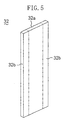
- FIG. 5 shows the second embodiment of the present invention (hereinafter, the same components as those shown in FIGS. 1 to 4 are denoted by the same reference numerals, whose description will be omitted).
- each magnet (32) is divided into three parts, the central magnet (33) positioned in the central portion in the width direction of the central insertion portion (31a) of the magnet insertion portion (31) and the end magnets (34) , (34) positioned at the end portions in the width direction of the central insertion portion (31a) of the magnet insertion portion (31) , and the end magnets (34) , (34) have greater coercive forces than the central magnet (33) , whereas the central magnet (33) has a greater magnetic flux density than the end magnets (34) , (34) .
- it is constituted such that one magnet (32) includes portions that have different magnetic flux and coercive force thereof in the width direction.
- each magnet (32) is not divided like the first embodiment, but consists of one magnet plate, and its magnetic flux density and coercive force are different along the peripheral direction (the width direction) of the joke (26).
- each of the magnet (32) includes one magnet central portion (32a) that is positioned at the central portion in the width direction of the central insertion portion (31a) of the magnet insertion portion (31) and magnet end portions (32b), (32b) that are positioned at end portions of the central insertion portion (31a), respective magnetic flux and coercive force of which are different from each other, and the magnet (32) has changing characteristics in such manner that the magnet central portion (32a) that is positioned where it is difficult to be demagnetized has a greater coercive force than the magnet end portions (32b) , (32b) that are positioned where it is easy to be demagnetized, whereas the magnet end portions (32b) , (32b) easy to be demagnetized have greater magnetic flux density than the magnet central portion (32a) difficult to be demagnetized.
- the present embodiment using the magnet (32) consisting of one plate can also provide the same function and effects as the first embodiment.
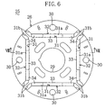
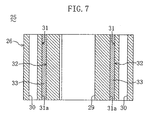
- FIGS. 6 and 7 show the third embodiment of the present invention. Differently from the first embodiment, the third embodiment is constituted such that the central magnet (33) has a greater force of retaining magnetic flux and the end magnets (34) , (34) have greater magnetic flux density.
- the position of the central insertion portion (31a) of each magnet insertion portion (31) at the yoke (26) of the rotor (25) of the electric motor (20) , namely the position of the each magnet (32) therein is placed close to the outer peripheral surface of the yoke (26) .
- Each of the magnet (32) is divided into three parts, the central magnet (33) that is positioned at the central portion in the width direction of the central insertion portion (31a) of the magnet insertion portion (31) and end magnets (34) , (34) that are positioned at end portions of the central insertion portion (31a) .
- the both magnets (33), (34) have different characteristics in such manner that the central magnet (33) has a greater coercive force than the end magnets (34) , (34) , whereas the end magnets (34) , (34) have greater magnetic flux density than the central magnet (33) .
- the central portion in the width direction of the magnet (32) becomes easier to be demagnetized than the end portion thereof due to the reverse magnetic filed (stator magnetic flux) caused by currents of the coils (23) of the stator (21) . Accordingly, the demagnetization of the magnet (32) can be prevented as a whole by the central magnet (3) , which is positioned at the central portion in the width direction of the central insertion portion (31a) , having greater coercive force than the end magnets (34) , (34) , which are positioned at the end portions.
- the end magnets (34) , (34) that are difficult to be demagnetized have greater magnetic flux density than the central magnet (33) , and thereby the max torque and the efficiency of the electric motor (20) can be improved by the magnetic flux density of the end magnets (34) , (34) . Accordingly, the present embodiment can also provide the similar function and effects to the first embodiment.
- the magnet (32) may consist of one plate magnet like the second embodiment. That is, magnetic flux density and coercive force of the one-plate magnet (32) are different along the peripheral direction of the joke (26) (the width direction of the magnet (32)), and the magnet (32) , as shown in FIG. 5 , has changing characteristics in such manner that the magnet end portions (32b) , (32b) that is difficult to be demagnetized have greater magnetic flux density than the magnet central portion (32a) that is easy to be demagnetized, whereas the magnet central portion (32a) easy to be demagnetized has a greater coercive force than the magnet end portions (32b) , (32b) difficult to be demagnetized.
- FIG. 8 shows the fourth embodiment.
- the central magnet (33) is inserted in and fixed to substantially the whole space of the central insertion portion (31a) of each magnet insertion portion (31)
- the end magnets (34) , (34) are inserted in and fixed to substantially the whole space of the both magnetic flux barrier portions (31b) , (31b) , which are constituted of air gaps (space) in the embodiments described above.
- This magnetic flux barrier (31b) is positioned where it is easy to be demagnetized by the reverse magnetic filed caused by the stator current, and the two end magnets (34) , (34) easy to be demagnetized have greater coercive forces than the central magnet (33) difficult to be demagnetized, whereas the central magnet (33) difficult to be demagnetized has a greater magnetic flux density than the end magnets (34) , (34) easy to be demagnetized.
- Other basic structures of the present embodiment are the same as the first embodiment.
- the motor torque of the electric motor (20) is provided by combining magnetic torque, which is a reaction force caused by the magnetic flux of the magnet (32) of the rotor (25) and the stator magnetic flux of the coils (23) of the stator (21) , and reluctance torque, which is a theory that can be applied to the above-described embodiments as well.
- the reluctance torque is a force for rotating the rotor (25) from a certain position to a particular position where the stator magnetic flux can flow the most easily, in which a degree how easily the stator magnetic flux flow through the rotor (25) changes depending upon its relative position to the rotor (25) , in the event that the yoke (26) of the rotor (25) has saliency.
- the magnet insertion portion (31) is constituted of only the central insertion portion (31a) (no magnetic flux barrier portion) (no magnetic flux barrier portion)
- the magnet insertion portion (31) includes the central insertion portion (31a) and a pair of the magnetic flux barrier portion (31b), (31b) extending subsequently from the central insertion portion (31a) (as shown in FIGS.
- the magnet insertion portion (31) can be regarded as air gaps (air), whether it is the central insertion portion (31a) or the magnetic barrier portion (31b) .
- the magnitude of the above-described reluctance torque is not influenced by the existence of the magnet in the magnet insertion portion (31) (the central insertion portion (31a) and the magnetic barrier portion (31b) ).
- the position of the rotor where the motor torque obtained by combining such reluctance torque and the magnet torque becomes a peak changes, and accordingly it is controlled according to the operating condition so that the motor torque can become as much as possible.
- the magnetic flux of the magnet of the structure in the forth embodiment is greater than that of the structure in the first embodiment, and thereby its magnetic torque described above becomes grater as well. Accordingly, the forth embodiment has an effect that the motor torque thereof is greater than that of the first embodiment and the like.
- one plate-shape magnet (32) having the cross section equivalent to the shape of the magnet insertion portion (31) may be inserted in the central insertion portion (31a) and the magnetic barrier portions (31b) , (31b) of the magnetic insertion portion (31) , in which its magnetic flux density and coercive force are different along the peripheral direction of the yoke (26) (the width direction of the magnet (32) ), and the magnet (32) has changing characteristics in such manner that the magnet central portion (32a) inserted in the central insertion portion (31a) that is positioned where it is difficult to be demagnetized has a greater magnetic flux density than the magnet end portions (32b), (32b) inserted in the magnetic flux barrier portion (31b), (31b) that are positioned where it is easy to be demagnetized, whereas the magnet end portions (32b), (32b) easy to be demagnetized have greater coercive forces than the magnet central portion (32a) difficult to be demagnetized
- the magnet (32) is constituted such that it is divided into three parts, the central portion (33) ; (32a) and two end portions (34) , (34) ; (32b) , (32b) .
- the magnet may be divided into two, or four or more, in which a portion that is positioned where it is easy to be demagnetized has a greater coercive force than a portion that is positioned where it is difficult to be demagnetized, whereas the portion difficult to be demagnetized has a greater magnetic flux density than the portion easy to be demagnetized.
- each magnet (32) is demagnetized by the reverse magnetic filed caused by the stator current flowing through the stator coils (23) .
- the present invention can be applied to the case where the demagnetization is achieved by heating, in which the magnitudes of their coercive force and magnetic flux density should be different respectively depending upon portions that are easy or difficult to be demagnetized by heating.
- the present invention is applied to the electric motor (20) as a motor for the compressor (C) .
- the present invention may be applied to any permanent magnet-type electric motors having other usages than the compressor.
- the present invention can prevent demagnetization of magnets as a whole without any cost increase by decreasing the amount of materials used for each magnet inserted in the rotor of the motor of the permanent magnet-type electric motor and improve the max torque and the efficiency of the electric motor by suppressing deterioration of magnetic flux density. Accordingly, the present invention has very high industrial applicability.
Landscapes
- Engineering & Computer Science (AREA)
- Power Engineering (AREA)
- Permanent Field Magnets Of Synchronous Machinery (AREA)
- Iron Core Of Rotating Electric Machines (AREA)
- Permanent Magnet Type Synchronous Machine (AREA)
Abstract
Description
Claims (11)
- A permanent magnet-type electric motor, comprising:wherein each of said magnet (32) is constituted of a plurality of magnets (33), (34) that are divided in the circumferential direction of yoke, and a magnet of the divided magnets that is positioned where it is easy to be demagnetized has a greater coercive force than a magnet of the divided magnets that is positioned where it is difficult to be demagnetized, whereas the magnet difficult to be demagnetized has a greater magnetic flux density than the magnet easy to be demagnetized.a stator (21); anda rotor (25) disposed in the stator (21), in which a plurality of permanent magnets (32), (32) forming a magnetic pole are inserted in magnet insertions (31), (31) of a yoke (26) in such manner that the magnets (32), (32) form in line in the circumferential direction thereof,
- The permanent magnet-type electric motor of claim 1, wherein each of said magnet (32) is divided into a central magnet (33) that is positioned at the central portion in the width direction of said magnet insertion portion (31) and end magnets (34), (34) that are positioned at end portions of said magnet insertion portion (31), and said central magnet (33) has a greater coercive force than the end magnets (34), (34), whereas said end magnets (34), (34) have greater magnetic flux density than the central magnet (33).
- The permanent magnet-type electric motor of claim 1, wherein each of said magnet (32) is divided into a central magnet (33) that is positioned at the central portion in the width direction of said magnet insertion portion (31) and end magnets (34), (34) that are positioned at end portions of said magnet insertion portion (31), and the central magnet (33) has a greater magnetic flux density than the end magnets (34), (34), whereas the end magnets (34), (34) have greater coercive forces than the central magnet (33).
- The permanent magnet-type electric motor of claims 2 or 3, wherein said magnet insertion portion (31) comprises a central insertion portion (31a) that is positioned at the central portion in the circumferential direction of the yoke (26) and magnetic flux barrier portions (31b), (31b) that extend outwardly and subsequently in substantially the radial direction of the yoke (26) from the both ends of the central insertion portion (31a), and said central magnet (33) and said end magnets (34), (34) are inserted only in said central insertion portion (31a).
- The permanent magnet-type electric motor of claim 3, wherein said magnet insertion portion (31) comprises a central insertion portion (31a) that is positioned at the central portion in the circumferential direction of the yoke (26) and magnetic flux barrier portions (31b), (31b) that extend outwardly and subsequently in substantially the radial direction of the yoke (26) from the both ends of the central insertion portion (31a), and said central magnet (33) is inserted in said central insertion portion (31a) and said end magnets (34), (34) are inserted in said magnetic flux barrier portions (31b), (31b), respectively.
- A permanent magnet-type electric motor, comprising:wherein each of said magnet (32) includes portions that have deferent magnetic flux and coercive force thereof in the circumferential direction of yoke, and a portion of the magnet (32) that is positioned where it is easy to be demagnetized has a greater coercive force than a portion of the magnet (32) that is positioned where it is difficult to be demagnetized, whereas the portion difficult to be demagnetized has a greater magnetic flux density than the portion easy to be demagnetized.a stator (21); anda rotor (25) disposed in the stator (21), in which a plurality of permanent magnets (32), (32) forming a magnetic pole are inserted in magnet insertions (31), (31) of a yoke (26) in such manner that the magnets (32), (32) form in line in the circumferential direction thereof,
- The permanent magnet-type electric motor of claim 6, wherein each of said magnet (32) includes a magnet central portion (32a) that is positioned at the central portion in the width direction of said magnet insertion portion (31) and magnet end portions (32b), (32b) that are positioned at end portions of said magnet insertion portion (31), respective magnetic flux and coercive force of which are different from each other, and said magnet central portion (32a) has a greater coercive force than the magnet end portions (32b), (32b), whereas the magnet end portions (32b), (32b) have greater magnetic flux density than the magnet central portion (32a).
- The permanent magnet-type electric motor of claim 6, wherein each of said magnet (32) includes a magnet central portion (32a) that is positioned at the central portion in the width direction of said magnet insertion portion (31) and magnet end portions (32b), (32b) that are positioned at end portions of said magnet insertion portion (31), respective magnetic flux and coercive force of which are different from each other, and said magnet central portion (32a) has a greater magnetic flux density than the magnet end portions (32b), (32b), whereas the magnet end portions (32b), (32b) have greater coercive forces than the magnet central portion (32a).
- The permanent magnet-type electric motor of claims 7 or 8, wherein said magnet insertion portion (31) comprises a central insertion portion (31a) that is positioned at the central portion in the circumferential direction of the yoke (26) and magnetic flux barrier portions (31b), (31b) that extend outwardly and subsequently in substantially the radial direction of the yoke (26) from the both ends of the central insertion portion (31a), and said magnet (32) is inserted only in said central insertion portion (31a).
- The permanent magnet-type electric motor of claim 8, wherein said magnet insertion portion (31) comprises a central insertion portion (31a) that is positioned at the central portion in the circumferential direction of the yoke (26) and magnetic flux barrier portions (31b), (31b) that extend outwardly and subsequently in substantially the radial direction of the yoke (26) from the both ends of the central insertion portion (31a), and said magnet (32) is inserted in said magnet insertion portion (31) in such manner that said magnet central portion (32a) is inserted in said central insertion portion (31a) and said magnet end portions (32b), (32b) are inserted in said magnetic flux barrier portions (31b), (31 b), respectively.
- A compressor comprising a casing (1) and a compressing mechanism (3), wherein the permanent magnet-type electric motor of any one of the preceding claims is installed in said casing (1) to be coupled to said compressing mechanism (3).
Applications Claiming Priority (3)
| Application Number | Priority Date | Filing Date | Title |
|---|---|---|---|
| JP2002077920 | 2002-03-20 | ||
| JP2002077920 | 2002-03-20 | ||
| PCT/JP2003/002281 WO2003079516A1 (en) | 2002-03-20 | 2003-02-27 | Permanent magnet type motor and compressor comprising it |
Publications (3)
| Publication Number | Publication Date |
|---|---|
| EP1487084A1 true EP1487084A1 (en) | 2004-12-15 |
| EP1487084A4 EP1487084A4 (en) | 2006-06-28 |
| EP1487084B1 EP1487084B1 (en) | 2014-08-06 |
Family
ID=28035547
Family Applications (1)
| Application Number | Title | Priority Date | Filing Date |
|---|---|---|---|
| EP03707160.2A Expired - Lifetime EP1487084B1 (en) | 2002-03-20 | 2003-02-27 | Permanent magnet type motor and compressor comprising it |
Country Status (10)
| Country | Link |
|---|---|
| US (1) | US6849981B2 (en) |
| EP (1) | EP1487084B1 (en) |
| JP (1) | JP4033132B2 (en) |
| KR (1) | KR100567130B1 (en) |
| CN (1) | CN1287503C (en) |
| BR (1) | BR0303575A (en) |
| ES (1) | ES2518928T3 (en) |
| MY (1) | MY122967A (en) |
| TW (1) | TWI274457B (en) |
| WO (1) | WO2003079516A1 (en) |
Cited By (5)
| Publication number | Priority date | Publication date | Assignee | Title |
|---|---|---|---|---|
| CN102057229A (en) * | 2008-06-09 | 2011-05-11 | 大金工业株式会社 | Air conditioner, air conditioner manufacturing method, and compressor |
| EP2216883A4 (en) * | 2007-11-28 | 2016-08-24 | Toshiba Kk | ROTOR OF ROTARY MACHINE |
| DE102019130986A1 (en) * | 2019-11-15 | 2021-05-20 | Hiwin Mikrosystem Corp. | Rotor structure of a permanent magnet motor |
| EP4418499A1 (en) * | 2023-01-31 | 2024-08-21 | Mazda Motor Corporation | Permanent magnet rotor for a rotary electric machine for a hybrid vehicle |
| EP4412042A3 (en) * | 2023-01-31 | 2024-11-27 | Mazda Motor Corporation | Permanent magnet rotor for a rotary electric machine |
Families Citing this family (73)
| Publication number | Priority date | Publication date | Assignee | Title |
|---|---|---|---|---|
| US7564153B2 (en) * | 2004-07-21 | 2009-07-21 | Ucer Mustafa O | Apparatus and method for producing mechanical work |
| US7902703B2 (en) * | 2004-07-21 | 2011-03-08 | Ucer Mustafa O | Apparatus and method for producing mechanical work |
| JP4791013B2 (en) * | 2004-07-22 | 2011-10-12 | 三菱電機株式会社 | Brushless motor |
| JP4668721B2 (en) * | 2004-11-30 | 2011-04-13 | 日立オートモティブシステムズ株式会社 | Permanent magnet rotating electric machine |
| JP2006197696A (en) * | 2005-01-12 | 2006-07-27 | Toyota Motor Corp | Rotor structure of rotating electrical machine |
| JP4010319B2 (en) * | 2005-02-09 | 2007-11-21 | ダイキン工業株式会社 | Core and rotor, motor and compressor |
| US7679252B2 (en) * | 2005-04-13 | 2010-03-16 | Aisin Seiki Kabushiki Kaisha | Magnet embedded motor, rotor unit, and method for manufacturing rotor unit |
| US7504754B2 (en) * | 2005-10-31 | 2009-03-17 | Caterpillar Inc. | Rotor having multiple permanent-magnet pieces in a cavity |
| EP1786085B1 (en) | 2005-11-15 | 2016-08-03 | Shin-Etsu Chemical Co., Ltd. | Permanent magnet rotating electric machine |
| JP4815204B2 (en) * | 2005-12-01 | 2011-11-16 | アイチエレック株式会社 | Permanent magnet rotating machine and compressor |
| EP1816725A1 (en) * | 2006-02-03 | 2007-08-08 | University of Teheran | Permanent magnet assembly for electric machines and actuators, method for their design and electric machines and actuators |
| JP4569542B2 (en) * | 2006-02-13 | 2010-10-27 | 株式会社デンソー | Electromagnetic switch and manufacturing method thereof |
| US8395199B2 (en) * | 2006-03-25 | 2013-03-12 | 4D-S Pty Ltd. | Systems and methods for fabricating self-aligned memory cell |
| US7385328B2 (en) * | 2006-05-23 | 2008-06-10 | Reliance Electric Technologies, Llc | Cogging reduction in permanent magnet machines |
| CN102170212B (en) * | 2006-08-23 | 2012-07-18 | 株式会社东芝 | Permanent magnet type rotating motor |
| US8044548B2 (en) * | 2006-08-23 | 2011-10-25 | Kabushiki Kaisha Toshiba | Permanent-magnet-type rotating electrical machine |
| KR101243670B1 (en) * | 2007-03-08 | 2013-03-18 | 엘지전자 주식회사 | Rotor of motor |
| JP4952786B2 (en) * | 2007-03-15 | 2012-06-13 | ダイキン工業株式会社 | Field element |
| US7932658B2 (en) * | 2007-03-15 | 2011-04-26 | A.O. Smith Corporation | Interior permanent magnet motor including rotor with flux barriers |
| JP5134846B2 (en) * | 2007-03-26 | 2013-01-30 | 株式会社東芝 | Permanent magnet motor drive system |
| JP5310544B2 (en) * | 2007-03-27 | 2013-10-09 | 日立金属株式会社 | Permanent magnet type rotating machine and manufacturing method thereof |
| WO2008137709A2 (en) * | 2007-05-04 | 2008-11-13 | A. O. Smith Corporation | Interior permanent magnet motor and rotor |
| US20100171386A1 (en) * | 2007-05-28 | 2010-07-08 | Toyota Jidosha Kabushiki Kaisha | Rotor for magnet-embedded motor and magnet-embedded motor |
| JP5332171B2 (en) * | 2007-10-19 | 2013-11-06 | 三菱電機株式会社 | Permanent magnet motor |
| EP2083503A3 (en) * | 2008-01-22 | 2017-03-29 | LG Electronics Inc. | Brushless direct current motor |
| JP2009201259A (en) * | 2008-02-21 | 2009-09-03 | Toshiba Corp | Permanent magnet type rotary electric machine, method of assembling permanent magnet type rotary electric machine, method of disassembling permanent magnet type rotary electric machine and drive system for permanent magnet electric motor |
| JP5305753B2 (en) * | 2008-06-20 | 2013-10-02 | 株式会社東芝 | Permanent magnet rotating electric machine |
| JP5361261B2 (en) * | 2008-06-20 | 2013-12-04 | 株式会社東芝 | Permanent magnet rotating electric machine |
| EP2304863B1 (en) * | 2008-07-30 | 2018-06-27 | Regal Beloit America, Inc. | Interior permanent magnet motor including rotor with unequal poles |
| JP5159577B2 (en) * | 2008-11-19 | 2013-03-06 | 株式会社東芝 | Permanent magnet rotating electric machine |
| JP5262643B2 (en) * | 2008-12-04 | 2013-08-14 | 信越化学工業株式会社 | Nd-based sintered magnet and manufacturing method thereof |
| KR101529925B1 (en) * | 2008-12-15 | 2015-06-18 | 엘지전자 주식회사 | Interior permanent magnet type brushless direct current motor and compressor having the same |
| JP5334295B2 (en) * | 2008-12-25 | 2013-11-06 | 東芝キヤリア株式会社 | Permanent magnet motor and hermetic compressor |
| JP5504637B2 (en) * | 2009-02-06 | 2014-05-28 | 日産自動車株式会社 | Electric motor and control method thereof |
| JP5299029B2 (en) * | 2009-03-31 | 2013-09-25 | 日産自動車株式会社 | Permanent magnet type motor |
| JP4687810B2 (en) * | 2009-03-31 | 2011-05-25 | 株式会社富士通ゼネラル | Electric motor rotor |
| WO2010150362A1 (en) * | 2009-06-24 | 2010-12-29 | トヨタ自動車株式会社 | Sintered magnet and method for producing the same |
| WO2011001533A1 (en) * | 2009-07-03 | 2011-01-06 | 三菱電機株式会社 | Permanent magnetic rotating electric machine |
| JP5469955B2 (en) * | 2009-08-12 | 2014-04-16 | 日立オートモティブシステムズ株式会社 | Rotating electric machine for vehicles |
| JP5454023B2 (en) * | 2009-09-07 | 2014-03-26 | ダイキン工業株式会社 | Electric motor |
| JP5600917B2 (en) * | 2009-10-01 | 2014-10-08 | 信越化学工業株式会社 | Rotor for permanent magnet rotating machine |
| EP2533403B1 (en) * | 2010-02-05 | 2019-09-04 | Shin-Etsu Chemical Co., Ltd. | Permanent magnet rotary machine |
| CN103038981A (en) * | 2010-07-30 | 2013-04-10 | 株式会社日立制作所 | Rotating electrical machine, and electric vehicle using same |
| CN102611216A (en) * | 2011-01-19 | 2012-07-25 | 株式会社安川电机 | Mixed type excitation permanent magnet, rotor for rotating electric machine using same and generator |
| EP2498267B1 (en) * | 2011-03-09 | 2017-06-14 | Siemens Aktiengesellschaft | Layered magnet |
| JP5773196B2 (en) * | 2011-07-19 | 2015-09-02 | アイシン・エィ・ダブリュ株式会社 | Rotating electric machine |
| JP5990890B2 (en) * | 2011-10-04 | 2016-09-14 | 日本精工株式会社 | Electric motor control device and electric power steering device |
| JP6095263B2 (en) * | 2011-11-10 | 2017-03-15 | 信越化学工業株式会社 | Embedded magnet type motor and compressor |
| CN103138442B (en) * | 2011-11-25 | 2016-04-13 | 丹佛斯(天津)有限公司 | The rotor of interior permanent magnet machines and use its interior permanent magnet machines |
| CN103166346A (en) * | 2011-12-19 | 2013-06-19 | 上海日立电器有限公司 | Magnetic steel group for IPM type permanent magnet motor rotor of hermetic compressor |
| EP2611002A3 (en) * | 2011-12-28 | 2015-07-08 | Remy Technologies, LLC | Dual magnet rotor |
| JP5786735B2 (en) * | 2012-01-30 | 2015-09-30 | ダイキン工業株式会社 | Permanent magnet manufacturing method and field element manufacturing method |
| JP5382156B2 (en) | 2012-03-06 | 2014-01-08 | 三菱電機株式会社 | Rotating electric machine |
| JP5891089B2 (en) * | 2012-03-29 | 2016-03-22 | 株式会社日立産機システム | Permanent magnet synchronous machine |
| JP6281147B2 (en) * | 2012-08-07 | 2018-02-21 | 日本電産株式会社 | Rotor and motor |
| CA2822158A1 (en) | 2012-08-17 | 2014-02-17 | Envision Energy (Denmark) Aps | Electrical machine with magnetic flux intensifier |
| MX347464B (en) | 2012-09-29 | 2017-04-26 | Emerson Electric Co | Rotors with segmented magnet configurations and related dynamoelectric machines and compressors. |
| WO2015045069A1 (en) * | 2013-09-26 | 2015-04-02 | 三菱電機株式会社 | Permanent magnet embedded electric motor, compressor, and refrigerating and air-conditioning device |
| KR101534706B1 (en) * | 2013-12-18 | 2015-07-07 | 현대자동차 주식회사 | Interior permanent magnet synchronous motor |
| JP2016010176A (en) * | 2014-06-20 | 2016-01-18 | 日本電産株式会社 | Motor |
| JP6223568B2 (en) * | 2014-07-01 | 2017-11-01 | 三菱電機株式会社 | Permanent magnet embedded electric motor, compressor and refrigeration air conditioner |
| US9673667B2 (en) | 2014-07-22 | 2017-06-06 | General Electric Company | System and method for preventing stator permanent magnet demagnetization during vacuum pressure impregnation |
| US9520752B1 (en) * | 2015-09-30 | 2016-12-13 | Faraday & Future Inc. | Interior permanent magnet machine for automotive electric vehicles |
| CN105811616A (en) * | 2016-03-23 | 2016-07-27 | 创驱(上海)新能源科技有限公司 | Tangential sectional type magnetic steel and permanent magnet synchronous motor rotor equipped with same |
| KR101925331B1 (en) | 2017-03-16 | 2018-12-05 | 엘지전자 주식회사 | Electric motor with permanent magnet and compressor having the same |
| EP3386075B1 (en) | 2017-04-06 | 2020-07-29 | LG Electronics Inc. | Electric motor with permament magnet and compressor having the same |
| KR101918065B1 (en) | 2017-04-06 | 2018-11-13 | 엘지전자 주식회사 | Electric motor with permanent magnet and compressor having the same |
| KR102459101B1 (en) * | 2018-03-12 | 2022-10-26 | 미쓰비시덴키 가부시키가이샤 | Electric motors, compressors, blowers, and refrigeration and air conditioning units |
| ES2983059T3 (en) * | 2018-06-27 | 2024-10-21 | Mitsubishi Electric Corp | Electric motor, blower and air conditioning device |
| WO2022016437A1 (en) * | 2020-07-23 | 2022-01-27 | 华为数字能源技术有限公司 | Electric motor rotor and electric motor |
| CN113113990B (en) * | 2021-04-07 | 2023-05-12 | 上海大学 | Permanent magnet pole of rotor of built-in permanent magnet motor and PC value evaluation method thereof |
| DE102021129036A1 (en) | 2021-11-08 | 2023-05-11 | Vaillant Gmbh | Compressor, air conditioner and use of a magnetic flux barrier or refrigerant |
| CN120728921B (en) * | 2025-08-18 | 2025-12-05 | 东方电气集团东方电机有限公司 | Wind power motor rotor using interelectrode pressing strips to fix permanent magnets and mounting method |
Family Cites Families (15)
| Publication number | Priority date | Publication date | Assignee | Title |
|---|---|---|---|---|
| DE2527461C2 (en) * | 1975-06-20 | 1987-01-02 | Robert Bosch Gmbh, 7000 Stuttgart | Process for the production of anisotropic segment magnets for electrical machines |
| JPH05236686A (en) * | 1992-02-20 | 1993-09-10 | Daikin Ind Ltd | Brushless DC motor |
| JPH07336980A (en) * | 1994-06-01 | 1995-12-22 | Nippondenso Co Ltd | Brushless dc motor |
| JP3167535B2 (en) * | 1994-06-21 | 2001-05-21 | 株式会社東芝 | Permanent magnet type rotating electric machine |
| JP3268152B2 (en) * | 1995-01-31 | 2002-03-25 | 株式会社東芝 | Permanent magnet field type rotating electric machine |
| JPH08336248A (en) * | 1995-06-08 | 1996-12-17 | Matsushita Electric Ind Co Ltd | Rotor with permanent magnet |
| JPH08340651A (en) * | 1995-06-12 | 1996-12-24 | Toshiba Corp | Permanent magnet and permanent magnet type rotating electrical machine |
| JP3509508B2 (en) * | 1997-02-21 | 2004-03-22 | アイシン・エィ・ダブリュ株式会社 | Permanent magnet synchronous motor |
| KR100252393B1 (en) * | 1997-05-13 | 2000-04-15 | 윤종용 | Structure of reclaimed magnet type rotor |
| JPH11355985A (en) * | 1998-06-04 | 1999-12-24 | Toshiba Corp | Permanent magnet type motor |
| DE19933009A1 (en) * | 1998-07-24 | 2000-02-10 | Matsushita Electric Industrial Co Ltd | Electric motor e.g. for automobile air conditioning unit, has rotor core provided with slits for reception of internal permanent magnets with non-magnetic section between each permanent magnet and rotor periphery |
| JP2000092763A (en) * | 1998-09-18 | 2000-03-31 | Toshiba Corp | Permanent magnet type motor |
| JP3602392B2 (en) * | 1999-12-21 | 2004-12-15 | アイチエレック株式会社 | Permanent magnet embedded motor |
| DE60141308D1 (en) * | 2000-03-31 | 2010-04-01 | Sanyo Electric Co | Synchronous motor with internal permanent magnet |
| JP3983004B2 (en) * | 2000-03-31 | 2007-09-26 | 山洋電気株式会社 | Synchronous motor with built-in permanent magnet |
-
2003
- 2003-02-27 EP EP03707160.2A patent/EP1487084B1/en not_active Expired - Lifetime
- 2003-02-27 JP JP2003577400A patent/JP4033132B2/en not_active Expired - Fee Related
- 2003-02-27 CN CNB038004151A patent/CN1287503C/en not_active Expired - Fee Related
- 2003-02-27 KR KR1020037017020A patent/KR100567130B1/en not_active Expired - Fee Related
- 2003-02-27 US US10/478,097 patent/US6849981B2/en not_active Expired - Lifetime
- 2003-02-27 BR BR0303575-1A patent/BR0303575A/en not_active Application Discontinuation
- 2003-02-27 ES ES03707160.2T patent/ES2518928T3/en not_active Expired - Lifetime
- 2003-02-27 WO PCT/JP2003/002281 patent/WO2003079516A1/en not_active Ceased
- 2003-03-07 TW TW092104961A patent/TWI274457B/en not_active IP Right Cessation
- 2003-03-20 MY MYPI20030980A patent/MY122967A/en unknown
Cited By (7)
| Publication number | Priority date | Publication date | Assignee | Title |
|---|---|---|---|---|
| EP2216883A4 (en) * | 2007-11-28 | 2016-08-24 | Toshiba Kk | ROTOR OF ROTARY MACHINE |
| CN102057229A (en) * | 2008-06-09 | 2011-05-11 | 大金工业株式会社 | Air conditioner, air conditioner manufacturing method, and compressor |
| CN102057229B (en) * | 2008-06-09 | 2013-12-18 | 大金工业株式会社 | Air conditioner, manufacturing method of air conditioner, and compressor |
| DE102019130986A1 (en) * | 2019-11-15 | 2021-05-20 | Hiwin Mikrosystem Corp. | Rotor structure of a permanent magnet motor |
| EP4418499A1 (en) * | 2023-01-31 | 2024-08-21 | Mazda Motor Corporation | Permanent magnet rotor for a rotary electric machine for a hybrid vehicle |
| EP4412042A3 (en) * | 2023-01-31 | 2024-11-27 | Mazda Motor Corporation | Permanent magnet rotor for a rotary electric machine |
| US12592623B2 (en) | 2023-01-31 | 2026-03-31 | Mazda Motor Corporation | Rotor structure of rotary electric machine |
Also Published As
| Publication number | Publication date |
|---|---|
| MY122967A (en) | 2006-05-31 |
| JPWO2003079516A1 (en) | 2005-07-21 |
| KR100567130B1 (en) | 2006-03-31 |
| TWI274457B (en) | 2007-02-21 |
| US6849981B2 (en) | 2005-02-01 |
| KR20040012989A (en) | 2004-02-11 |
| CN1516915A (en) | 2004-07-28 |
| EP1487084B1 (en) | 2014-08-06 |
| AU2003211194A1 (en) | 2003-09-29 |
| JP4033132B2 (en) | 2008-01-16 |
| WO2003079516A1 (en) | 2003-09-25 |
| EP1487084A4 (en) | 2006-06-28 |
| ES2518928T3 (en) | 2014-11-05 |
| BR0303575A (en) | 2004-04-20 |
| US20040145263A1 (en) | 2004-07-29 |
| CN1287503C (en) | 2006-11-29 |
| TW200401492A (en) | 2004-01-16 |
Similar Documents
| Publication | Publication Date | Title |
|---|---|---|
| EP1487084B1 (en) | Permanent magnet type motor and compressor comprising it | |
| JP5835928B2 (en) | Electric motor and electric compressor using the same | |
| US11437877B2 (en) | Rotor, motor, compressor, and air conditioner | |
| CN104081631B (en) | Motor and employ the motor compressor of this motor | |
| US6147428A (en) | Rotor of electric motor | |
| US11183892B2 (en) | Consequent pole type rotor, motor having the same, compressor having the same, and fan having the same | |
| JP6055189B2 (en) | Permanent magnet rotating electric machine | |
| CN104871409B (en) | Permanent magnet embedded motors and compressors | |
| JP2005210826A (en) | Electric motor | |
| US20190181708A1 (en) | Rotary electrical machine | |
| KR102172260B1 (en) | Motor and compressor having thereof | |
| US11050310B2 (en) | Rotor, motor, fan, compressor, and air conditioning apparatus | |
| JP7026811B2 (en) | Stator, motor, compressor and air conditioner | |
| JP2013099064A (en) | Permanent magnet type motor and sealed type compressor using the same | |
| JP5454023B2 (en) | Electric motor | |
| JP7256432B1 (en) | Rotors, motors, compressors and air conditioners | |
| JP2025078208A (en) | Electric motor, and air conditioner, refrigerator, and in-vehicle device equipped with the electric motor |
Legal Events
| Date | Code | Title | Description |
|---|---|---|---|
| PUAI | Public reference made under article 153(3) epc to a published international application that has entered the european phase |
Free format text: ORIGINAL CODE: 0009012 |
|
| 17P | Request for examination filed |
Effective date: 20031125 |
|
| AK | Designated contracting states |
Kind code of ref document: A1 Designated state(s): AT BE BG CH CY CZ DE DK EE ES FI FR GB GR HU IE IT LI LU MC NL PT SE SI SK TR |
|
| A4 | Supplementary search report drawn up and despatched |
Effective date: 20060530 |
|
| 17Q | First examination report despatched |
Effective date: 20070716 |
|
| GRAP | Despatch of communication of intention to grant a patent |
Free format text: ORIGINAL CODE: EPIDOSNIGR1 |
|
| INTG | Intention to grant announced |
Effective date: 20140327 |
|
| GRAS | Grant fee paid |
Free format text: ORIGINAL CODE: EPIDOSNIGR3 |
|
| GRAA | (expected) grant |
Free format text: ORIGINAL CODE: 0009210 |
|
| AK | Designated contracting states |
Kind code of ref document: B1 Designated state(s): AT BE BG CH CY CZ DE DK EE ES FI FR GB GR HU IE IT LI LU MC NL PT SE SI SK TR |
|
| REG | Reference to a national code |
Ref country code: GB Ref legal event code: FG4D |
|
| REG | Reference to a national code |
Ref country code: AT Ref legal event code: REF Ref document number: 681421 Country of ref document: AT Kind code of ref document: T Effective date: 20140815 Ref country code: CH Ref legal event code: EP |
|
| REG | Reference to a national code |
Ref country code: IE Ref legal event code: FG4D |
|
| REG | Reference to a national code |
Ref country code: DE Ref legal event code: R096 Ref document number: 60346590 Country of ref document: DE Effective date: 20140918 |
|
| REG | Reference to a national code |
Ref country code: ES Ref legal event code: FG2A Ref document number: 2518928 Country of ref document: ES Kind code of ref document: T3 Effective date: 20141105 |
|
| REG | Reference to a national code |
Ref country code: AT Ref legal event code: MK05 Ref document number: 681421 Country of ref document: AT Kind code of ref document: T Effective date: 20140806 |
|
| REG | Reference to a national code |
Ref country code: NL Ref legal event code: VDEP Effective date: 20140806 |
|
| PG25 | Lapsed in a contracting state [announced via postgrant information from national office to epo] |
Ref country code: FI Free format text: LAPSE BECAUSE OF FAILURE TO SUBMIT A TRANSLATION OF THE DESCRIPTION OR TO PAY THE FEE WITHIN THE PRESCRIBED TIME-LIMIT Effective date: 20140806 Ref country code: PT Free format text: LAPSE BECAUSE OF FAILURE TO SUBMIT A TRANSLATION OF THE DESCRIPTION OR TO PAY THE FEE WITHIN THE PRESCRIBED TIME-LIMIT Effective date: 20141209 Ref country code: SE Free format text: LAPSE BECAUSE OF FAILURE TO SUBMIT A TRANSLATION OF THE DESCRIPTION OR TO PAY THE FEE WITHIN THE PRESCRIBED TIME-LIMIT Effective date: 20140806 Ref country code: GR Free format text: LAPSE BECAUSE OF FAILURE TO SUBMIT A TRANSLATION OF THE DESCRIPTION OR TO PAY THE FEE WITHIN THE PRESCRIBED TIME-LIMIT Effective date: 20141107 Ref country code: BG Free format text: LAPSE BECAUSE OF FAILURE TO SUBMIT A TRANSLATION OF THE DESCRIPTION OR TO PAY THE FEE WITHIN THE PRESCRIBED TIME-LIMIT Effective date: 20141106 |
|
| PG25 | Lapsed in a contracting state [announced via postgrant information from national office to epo] |
Ref country code: CY Free format text: LAPSE BECAUSE OF FAILURE TO SUBMIT A TRANSLATION OF THE DESCRIPTION OR TO PAY THE FEE WITHIN THE PRESCRIBED TIME-LIMIT Effective date: 20140806 Ref country code: AT Free format text: LAPSE BECAUSE OF FAILURE TO SUBMIT A TRANSLATION OF THE DESCRIPTION OR TO PAY THE FEE WITHIN THE PRESCRIBED TIME-LIMIT Effective date: 20140806 Ref country code: NL Free format text: LAPSE BECAUSE OF FAILURE TO SUBMIT A TRANSLATION OF THE DESCRIPTION OR TO PAY THE FEE WITHIN THE PRESCRIBED TIME-LIMIT Effective date: 20140806 |
|
| PG25 | Lapsed in a contracting state [announced via postgrant information from national office to epo] |
Ref country code: EE Free format text: LAPSE BECAUSE OF FAILURE TO SUBMIT A TRANSLATION OF THE DESCRIPTION OR TO PAY THE FEE WITHIN THE PRESCRIBED TIME-LIMIT Effective date: 20140806 Ref country code: CZ Free format text: LAPSE BECAUSE OF FAILURE TO SUBMIT A TRANSLATION OF THE DESCRIPTION OR TO PAY THE FEE WITHIN THE PRESCRIBED TIME-LIMIT Effective date: 20140806 Ref country code: SK Free format text: LAPSE BECAUSE OF FAILURE TO SUBMIT A TRANSLATION OF THE DESCRIPTION OR TO PAY THE FEE WITHIN THE PRESCRIBED TIME-LIMIT Effective date: 20140806 Ref country code: DK Free format text: LAPSE BECAUSE OF FAILURE TO SUBMIT A TRANSLATION OF THE DESCRIPTION OR TO PAY THE FEE WITHIN THE PRESCRIBED TIME-LIMIT Effective date: 20140806 |
|
| REG | Reference to a national code |
Ref country code: DE Ref legal event code: R097 Ref document number: 60346590 Country of ref document: DE |
|
| PLBE | No opposition filed within time limit |
Free format text: ORIGINAL CODE: 0009261 |
|
| STAA | Information on the status of an ep patent application or granted ep patent |
Free format text: STATUS: NO OPPOSITION FILED WITHIN TIME LIMIT |
|
| PG25 | Lapsed in a contracting state [announced via postgrant information from national office to epo] |
Ref country code: BE Free format text: LAPSE BECAUSE OF NON-PAYMENT OF DUE FEES Effective date: 20150228 |
|
| 26N | No opposition filed |
Effective date: 20150507 |
|
| REG | Reference to a national code |
Ref country code: DE Ref legal event code: R119 Ref document number: 60346590 Country of ref document: DE |
|
| PG25 | Lapsed in a contracting state [announced via postgrant information from national office to epo] |
Ref country code: LU Free format text: LAPSE BECAUSE OF FAILURE TO SUBMIT A TRANSLATION OF THE DESCRIPTION OR TO PAY THE FEE WITHIN THE PRESCRIBED TIME-LIMIT Effective date: 20150227 |
|
| REG | Reference to a national code |
Ref country code: CH Ref legal event code: PL |
|
| GBPC | Gb: european patent ceased through non-payment of renewal fee |
Effective date: 20150227 |
|
| PG25 | Lapsed in a contracting state [announced via postgrant information from national office to epo] |
Ref country code: LI Free format text: LAPSE BECAUSE OF NON-PAYMENT OF DUE FEES Effective date: 20150228 Ref country code: MC Free format text: LAPSE BECAUSE OF FAILURE TO SUBMIT A TRANSLATION OF THE DESCRIPTION OR TO PAY THE FEE WITHIN THE PRESCRIBED TIME-LIMIT Effective date: 20140806 Ref country code: CH Free format text: LAPSE BECAUSE OF NON-PAYMENT OF DUE FEES Effective date: 20150228 |
|
| REG | Reference to a national code |
Ref country code: IE Ref legal event code: MM4A |
|
| PG25 | Lapsed in a contracting state [announced via postgrant information from national office to epo] |
Ref country code: SI Free format text: LAPSE BECAUSE OF FAILURE TO SUBMIT A TRANSLATION OF THE DESCRIPTION OR TO PAY THE FEE WITHIN THE PRESCRIBED TIME-LIMIT Effective date: 20140806 |
|
| REG | Reference to a national code |
Ref country code: FR Ref legal event code: PLFP Year of fee payment: 14 |
|
| PG25 | Lapsed in a contracting state [announced via postgrant information from national office to epo] |
Ref country code: DE Free format text: LAPSE BECAUSE OF NON-PAYMENT OF DUE FEES Effective date: 20150901 Ref country code: IE Free format text: LAPSE BECAUSE OF NON-PAYMENT OF DUE FEES Effective date: 20150227 Ref country code: GB Free format text: LAPSE BECAUSE OF NON-PAYMENT OF DUE FEES Effective date: 20150227 |
|
| PG25 | Lapsed in a contracting state [announced via postgrant information from national office to epo] |
Ref country code: BE Free format text: LAPSE BECAUSE OF FAILURE TO SUBMIT A TRANSLATION OF THE DESCRIPTION OR TO PAY THE FEE WITHIN THE PRESCRIBED TIME-LIMIT Effective date: 20140806 |
|
| REG | Reference to a national code |
Ref country code: FR Ref legal event code: PLFP Year of fee payment: 15 |
|
| PG25 | Lapsed in a contracting state [announced via postgrant information from national office to epo] |
Ref country code: HU Free format text: LAPSE BECAUSE OF FAILURE TO SUBMIT A TRANSLATION OF THE DESCRIPTION OR TO PAY THE FEE WITHIN THE PRESCRIBED TIME-LIMIT; INVALID AB INITIO Effective date: 20030227 |
|
| PGFP | Annual fee paid to national office [announced via postgrant information from national office to epo] |
Ref country code: ES Payment date: 20170110 Year of fee payment: 15 Ref country code: TR Payment date: 20170126 Year of fee payment: 15 Ref country code: IT Payment date: 20170221 Year of fee payment: 15 |
|
| REG | Reference to a national code |
Ref country code: FR Ref legal event code: PLFP Year of fee payment: 16 |
|
| PGFP | Annual fee paid to national office [announced via postgrant information from national office to epo] |
Ref country code: FR Payment date: 20180111 Year of fee payment: 16 |
|
| PG25 | Lapsed in a contracting state [announced via postgrant information from national office to epo] |
Ref country code: IT Free format text: LAPSE BECAUSE OF NON-PAYMENT OF DUE FEES Effective date: 20180227 |
|
| REG | Reference to a national code |
Ref country code: ES Ref legal event code: FD2A Effective date: 20190801 |
|
| PG25 | Lapsed in a contracting state [announced via postgrant information from national office to epo] |
Ref country code: ES Free format text: LAPSE BECAUSE OF NON-PAYMENT OF DUE FEES Effective date: 20180228 |
|
| PG25 | Lapsed in a contracting state [announced via postgrant information from national office to epo] |
Ref country code: FR Free format text: LAPSE BECAUSE OF NON-PAYMENT OF DUE FEES Effective date: 20190228 |
|
| PG25 | Lapsed in a contracting state [announced via postgrant information from national office to epo] |
Ref country code: TR Free format text: LAPSE BECAUSE OF NON-PAYMENT OF DUE FEES Effective date: 20180227 |