EP1487066A1 - Schwimmend gelagerter Steckverbinder und dessen Herstellungsverfahren - Google Patents
Schwimmend gelagerter Steckverbinder und dessen Herstellungsverfahren Download PDFInfo
- Publication number
- EP1487066A1 EP1487066A1 EP04253468A EP04253468A EP1487066A1 EP 1487066 A1 EP1487066 A1 EP 1487066A1 EP 04253468 A EP04253468 A EP 04253468A EP 04253468 A EP04253468 A EP 04253468A EP 1487066 A1 EP1487066 A1 EP 1487066A1
- Authority
- EP
- European Patent Office
- Prior art keywords
- contacts
- parts
- contact
- housing
- elastic
- Prior art date
- Legal status (The legal status is an assumption and is not a legal conclusion. Google has not performed a legal analysis and makes no representation as to the accuracy of the status listed.)
- Granted
Links
- 238000004519 manufacturing process Methods 0.000 title claims abstract description 12
- 238000000034 method Methods 0.000 title claims description 7
- 230000013011 mating Effects 0.000 claims abstract description 55
- AGCPZMJBXSCWQY-UHFFFAOYSA-N 1,1,2,3,4-pentachlorobutane Chemical compound ClCC(Cl)C(Cl)C(Cl)Cl AGCPZMJBXSCWQY-UHFFFAOYSA-N 0.000 description 17
- 239000002184 metal Substances 0.000 description 13
- 238000005476 soldering Methods 0.000 description 9
- LAXBNTIAOJWAOP-UHFFFAOYSA-N 2-chlorobiphenyl Chemical compound ClC1=CC=CC=C1C1=CC=CC=C1 LAXBNTIAOJWAOP-UHFFFAOYSA-N 0.000 description 5
- 101710149812 Pyruvate carboxylase 1 Proteins 0.000 description 5
- 239000000463 material Substances 0.000 description 5
- 238000005192 partition Methods 0.000 description 3
- MINPZZUPSSVGJN-UHFFFAOYSA-N 1,1,1,4,4,4-hexachlorobutane Chemical compound ClC(Cl)(Cl)CCC(Cl)(Cl)Cl MINPZZUPSSVGJN-UHFFFAOYSA-N 0.000 description 2
- 101150049492 DVR gene Proteins 0.000 description 2
- 230000015572 biosynthetic process Effects 0.000 description 2
- 238000000465 moulding Methods 0.000 description 2
- 230000004075 alteration Effects 0.000 description 1
- 238000010276 construction Methods 0.000 description 1
- 230000002950 deficient Effects 0.000 description 1
- 238000003780 insertion Methods 0.000 description 1
- 230000037431 insertion Effects 0.000 description 1
- 238000012986 modification Methods 0.000 description 1
- 230000004048 modification Effects 0.000 description 1
- 229920005989 resin Polymers 0.000 description 1
- 239000011347 resin Substances 0.000 description 1
- 238000000926 separation method Methods 0.000 description 1
- 229920003002 synthetic resin Polymers 0.000 description 1
- 239000000057 synthetic resin Substances 0.000 description 1
Images


Classifications
-
- H—ELECTRICITY
- H01—ELECTRIC ELEMENTS
- H01R—ELECTRICALLY-CONDUCTIVE CONNECTIONS; STRUCTURAL ASSOCIATIONS OF A PLURALITY OF MUTUALLY-INSULATED ELECTRICAL CONNECTING ELEMENTS; COUPLING DEVICES; CURRENT COLLECTORS
- H01R13/00—Details of coupling devices of the kinds covered by groups H01R12/70 or H01R24/00 - H01R33/00
- H01R13/62—Means for facilitating engagement or disengagement of coupling parts or for holding them in engagement
- H01R13/629—Additional means for facilitating engagement or disengagement of coupling parts, e.g. aligning or guiding means, levers, gas pressure electrical locking indicators, manufacturing tolerances
- H01R13/631—Additional means for facilitating engagement or disengagement of coupling parts, e.g. aligning or guiding means, levers, gas pressure electrical locking indicators, manufacturing tolerances for engagement only
- H01R13/6315—Additional means for facilitating engagement or disengagement of coupling parts, e.g. aligning or guiding means, levers, gas pressure electrical locking indicators, manufacturing tolerances for engagement only allowing relative movement between coupling parts, e.g. floating connection
-
- E—FIXED CONSTRUCTIONS
- E01—CONSTRUCTION OF ROADS, RAILWAYS, OR BRIDGES
- E01D—CONSTRUCTION OF BRIDGES, ELEVATED ROADWAYS OR VIADUCTS; ASSEMBLY OF BRIDGES
- E01D19/00—Structural or constructional details of bridges
- E01D19/06—Arrangement, construction or bridging of expansion joints
- E01D19/065—Joints having sliding plates
-
- E—FIXED CONSTRUCTIONS
- E01—CONSTRUCTION OF ROADS, RAILWAYS, OR BRIDGES
- E01D—CONSTRUCTION OF BRIDGES, ELEVATED ROADWAYS OR VIADUCTS; ASSEMBLY OF BRIDGES
- E01D19/00—Structural or constructional details of bridges
- E01D19/08—Damp-proof or other insulating layers; Drainage arrangements or devices ; Bridge deck surfacings
- E01D19/086—Drainage arrangements or devices
-
- H—ELECTRICITY
- H01—ELECTRIC ELEMENTS
- H01R—ELECTRICALLY-CONDUCTIVE CONNECTIONS; STRUCTURAL ASSOCIATIONS OF A PLURALITY OF MUTUALLY-INSULATED ELECTRICAL CONNECTING ELEMENTS; COUPLING DEVICES; CURRENT COLLECTORS
- H01R43/00—Apparatus or processes specially adapted for manufacturing, assembling, maintaining, or repairing of line connectors or current collectors or for joining electric conductors
- H01R43/20—Apparatus or processes specially adapted for manufacturing, assembling, maintaining, or repairing of line connectors or current collectors or for joining electric conductors for assembling or disassembling contact members with insulating base, case or sleeve
-
- H—ELECTRICITY
- H01—ELECTRIC ELEMENTS
- H01R—ELECTRICALLY-CONDUCTIVE CONNECTIONS; STRUCTURAL ASSOCIATIONS OF A PLURALITY OF MUTUALLY-INSULATED ELECTRICAL CONNECTING ELEMENTS; COUPLING DEVICES; CURRENT COLLECTORS
- H01R12/00—Structural associations of a plurality of mutually-insulated electrical connecting elements, specially adapted for printed circuits, e.g. printed circuit boards [PCB], flat or ribbon cables, or like generally planar structures, e.g. terminal strips, terminal blocks; Coupling devices specially adapted for printed circuits, flat or ribbon cables, or like generally planar structures; Terminals specially adapted for contact with, or insertion into, printed circuits, flat or ribbon cables, or like generally planar structures
- H01R12/70—Coupling devices
- H01R12/7076—Coupling devices for connection between PCB and component, e.g. display
-
- H—ELECTRICITY
- H01—ELECTRIC ELEMENTS
- H01R—ELECTRICALLY-CONDUCTIVE CONNECTIONS; STRUCTURAL ASSOCIATIONS OF A PLURALITY OF MUTUALLY-INSULATED ELECTRICAL CONNECTING ELEMENTS; COUPLING DEVICES; CURRENT COLLECTORS
- H01R12/00—Structural associations of a plurality of mutually-insulated electrical connecting elements, specially adapted for printed circuits, e.g. printed circuit boards [PCB], flat or ribbon cables, or like generally planar structures, e.g. terminal strips, terminal blocks; Coupling devices specially adapted for printed circuits, flat or ribbon cables, or like generally planar structures; Terminals specially adapted for contact with, or insertion into, printed circuits, flat or ribbon cables, or like generally planar structures
- H01R12/70—Coupling devices
- H01R12/71—Coupling devices for rigid printing circuits or like structures
- H01R12/712—Coupling devices for rigid printing circuits or like structures co-operating with the surface of the printed circuit or with a coupling device exclusively provided on the surface of the printed circuit
- H01R12/716—Coupling device provided on the PCB
Definitions
- the present invention relates to a floating connector and a method for manufacturing therefor.
- a technique may be used in which a female type connector is fastened to one circuit board, a male type connector is fastened to the other circuit board, and these female and male type connectors are mated and connected to each other.
- the positions of the pair of connectors that are mated are predetermined on the circuit boards, so that the degree of freedom is relatively limited.
- one of the connectors has flexibility, not only is normal mating and connection of the two connectors impossible, but at least one of the connectors or the contacts of this connector are damaged or permanently deformed, so that such a connection is deficient in terms of reliability.
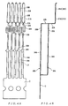
- the connector shown in Figs. 7(A), 7(B) and 8(A) to 8(C) is such a known floating connector and described in Japanese utility model application Kokai No S64-16084.
- the floating connector 101 is fastened to one circuit board PCB, and is mated and connected with a mating connector 131 which is fastened to another circuit board PCB that is disposed perpendicular to this first circuit board PCB.
- the mating connector 131 comprises a housing 140 which extends in the direction of length (i.e., the direction perpendicular to the plane of the page in Fig. 7 (A), or the left-right direction in Fig. 7 (B)), and a plurality of pin contacts 150 which are attached in two rows in the direction of length of the housing 140.
- Each of the pin contacts 150 comprises a board connection part which is connected by soldering to the second circuit board PCB, and a pin contact part which extends vertically downward from the board connection part.
- the floating connector 101 comprises a housing 110 which extends in the direction of length (i.e., the direction perpendicular to the plane of the page in Fig. 7 (A), or the left-right direction in Fig. 7 (B)), and a plurality of contacts 120 which are attached in two rows in the direction of length of the housing 110.
- Each contact 120 comprises a fastening part 121 which is fastened to the housing 110, a soldering tine part 123 which is connected to the first circuit board PCB, and a pair of contact pieces 124 which contact the corresponding pin contact 150.
- These contacts 120 are formed by stamping and forming metal plates.
- the fastening part 121 is formed substantially in a box shape comprising a pair of side walls 121a that are separated from each other by a specified interval in the direction of length of the housing 110, a front end wall 121b which extends in the direction of length from the front end portion (lower end portion in Fig.
- a connecting part 122 which extends rearwardly toward the center of the fastening part 121 perpendicular to the direction of length is formed by being bent on the end of the front end wall 121b of the fastening part 121, and a soldering tine part 123 extends downward from the rear end portion of this connecting part 122.
- the pair of contact pieces 124 extend upward from the respective side walls 121a of the fastening part 121, and contact projecting parts 125 are formed on the facing surfaces of the tip ends of these contact pieces 124.
- the floating connector 101 is mounted on the circuit board PCB by the soldering connection of the soldering tine parts 123 of the contacts 120 to the circuit board PCB as shown in Figs. 7(A) and 7(B). Furthermore, when the mating connector 131 is mated with the floating connector 101, the pin contacts 150 contact the contact projecting parts 125 of the contacts 120, so that an electrical connection is established between the connectors.
- the floating connector 101 is constructed so that this connector can move elastically in at least the horizontal direction (the direction of length of the housing 110 and the direction perpendicular to this direction of length) with respect to the surface of the first circuit board PCB, so that strain that is created when mating with the mating connector 131 is absorbed.
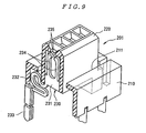
- the connector shown in Fig. 9 is another known example of a floating connector which is devised so that strain created at the time of mating with the mating connector is absorbed and described in Japanese patent application Kokai No H4-370677.
- the floating connector 201 is fastened to the surface of one circuit board (not shown in the figures), and is mated and connected with a mating connector (not shown in the figures) fastened to another circuit board (not shown in the figures).
- the floating connector 201 comprises a substantially frame-form first housing 210 which extends in the direction of length, and a second housing 220 which is inserted into an opening 211 in the housing 210 so that a gap is left.
- a plurality of contacts 230 disposed in a single row in the direction of length are attached to the second housing 220.
- Each contact 230 comprises a fastening part 231 which is fastened to the second housing 220, a strain absorbing part 232, a board connection part 233 which is connected to the circuit board, and a pair of contact parts 234 which contact a mating contact (not shown in the figures).
- These contacts 230 are formed in a substantially flat plate shape.
- the fastening part 231 is formed into a substantially rectangular shape which is formed exclusively by the stamping of a metal plate.
- the strain absorbing part 232 is formed into an elastic shape which extends from the lower end of the fastening part 231 via a plurality of curvilinear parts, and is formed exclusively by the stamping of the metal plate.
- the board connection part 233 is formed so that this part extends downward from the end portion of the strain absorbing part 232, and is formed by the stamping and forming of the metal plate. Furthermore, the pair of contact parts 234 extend upward from the fastening part 231, and contact projecting parts 235 are formed on the facing surfaces of the tip ends of these contact parts 234.
- the floating connector 201 is mounted on the circuit board by connecting the board connection parts 233 of the contacts 230 to the circuit board by soldering. Then, when the mating connector is mated with the floating connector 201, the mating contacts contact the contact projecting parts 235 of the contacts 230, so that an electrical connection is established between the connectors.
- the second housing 220 of the floating connector 201 is constructed so that this housing can move elastically in at least the horizontal direction (the direction of length of the second housing 220 and the direction perpendicular to this direction of length) as a result of the board connecting parts 233 extending downward from the strain absorbing parts 232 that are formed in an elastic shape with a plurality of curvilinear parts, thus causing the strain that is generated when mating with the mating connector to be absorbed.
- each contact 120 is separately attached to the housing 110 after being cut from a contact carrier. Accordingly, such a connector is inferior in terms of the connector assembly productivity.
- the contacts 230 are formed exclusively by the stamping of metal plates except for the base connection parts 233; accordingly, the productivity of the contacts 230 is good.
- the plurality of contacts 230 are fastened to the second housing 220, the plurality of contacts 230 are not all fastened to the second housing 220 at one time; instead, each contact 230 is separately attached to the second housing 220 after being cut from a contact carrier. Accordingly, such a connector is inferior in terms of the connector assembly productivity.
- the planes of the strain absorbing parts 232 and base connection parts 233 attached to the contact carrier in the state in which the metal plates have been stamped differ from the row disposition direction of the contacts 230 (the direction in which the contacts 230 are lined up in row form in the second housing 220, i.e., the direction of length of the second housing 220); accordingly, the plurality of contacts 230 cannot be inserted into the second housing 220 at one time.
- each contact 230 is formed in a substantially flat plate shape, the dimension of each contact 230 in the attachment pitch direction, i.e., the direction of length of the second housing 220, is small; however, since the strain absorbing part 233 of each contact 230 extends via a plurality of curvilinear parts, the contact 230 has a relatively large dimension in the direction perpendicular to this direction of length. Accordingly, it is difficult to use such a connector in recent compact high-density electronic devices.
- the present invention was devised in the light of the problems described above, and it is an object of the present invention to provide a floating connector which is superior in terms of contact productivity and connector assembly productivity, and which allows a compact high-density configuration to be obtained, and a method for manufacturing such a floating connector.
- the floating connector according to Claim 1 is a floating connector comprising an insulating housing and a plurality of contacts disposed in at least one row in this housing, wherein each of these contacts has a fastening part which is fastened to the housing, a contact part which contacts the corresponding mating contact, a leg part which is connected to a circuit board, and a curvilinear elastic part which is disposed between the fastening part and the leg part, the plane of the elastic part extends in the contact row disposition direction, and a bent part is formed between the fastening part and the elastic part or between the elastic part and the leg part, so that the respective leg parts of the plurality of contacts are arranged in a staggered configuration in the contact row disposition direction.
- the floating connector according to Claim 2 comprises a connector according to Claim 1, wherein the positions of the elastic parts are shifted along the axial direction of the contacts so that the elastic parts of adjacent contacts do not interfere with each other in the state in which the plurality of contacts are stamped.
- the floating connector manufacturing method comprises the steps of stamping a plurality of contacts arranged in a single row, in which each contact has a fastening part which is fastened to a housing, a contact part which contacts the corresponding mating contact, a leg part which is connected to a circuit board, and a curvilinear elastic part which is disposed between the fastening part and the leg part, and the positions of the elastic parts are shifted along the axial direction of the contacts so that the elastic parts of adjacent contacts do not interfere with each other, forming a bent part between the fastening part and the elastic part or between the elastic part and the leg part of each contact, so that the respective leg parts of the plurality of contacts are arranged in a staggered configuration, inserting the plurality of contacts arranged in a single row into the housing at one time or as a single operation, and cutting the tip ends of the leg parts of the respective contacts from a contact carrier.
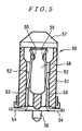
- the floating connector 1 is fastened to one circuit board PCB1, and is mated and connected with a mating connector 50 that is fastened to another circuit board PCB2.
- the mating connector 50 comprises an insulating housing 51 which extends in the direction of length (i.e., the direction perpendicular to the plane of the page in Fig. 5), and a plurality of mating contacts 52 which are attached in two rows along the direction of length of the housing 51.
- a connector receiving recess 58 which extends in the direction of length is formed in the housing 51.
- Each of the mating contacts 52 comprises a fastening part 53 which is fastened to the housing 51, a board connection part 54 which extends downward from the lower end of the fastening part 53 and which is connected by soldering to the other circuit board PCB, and an elastic contact part 55 which extends toward the inside of the connector receiving recess 58 from the upper end of the fastening part 53.
- the floating connector 1 comprises an insulating housing 10 which extends in the direction of length (the left-right direction in Fig. 1 (B), or the direction perpendicular to the plane of the page in Fig. 2), and a plurality of contacts 30 which are disposed in two rows along the direction of length of the housing 10.
- the housing 10 comprises a main body part 11 which extends in the direction of length, and a mating part 12 which protrudes upward from the upper surface of this main body part 11 and extends in the direction of length; this housing 10 is formed by molding an insulating synthetic resin. Opening parts 13 are formed which open in the forward-rearward direction (left-right direction in Fig. 2) with respect to the main body part 11 and in the bottom direction of the main body part 11. Furthermore, a mating connector receiving recess 14 which receives the housing 51 of the mating connector 50 is formed along the direction of length in the mating part 12.
- partition walls 15 which protrude from the bottom part of this mating connector receiving recess 14 and are inserted into the connector receiving recess 58 of the mating connector 50 are formed in the center of the interior part of the mating connector receiving recess 14.
- post receiving recesses 16 which receive the guide posts 57 of the mating connector 50 are formed in both outside ends of the mating connector receiving recess 14 of the mating part 12 with respect to the direction of length.
- leg parts of the contacts 30 of the respective rows are disposed in a staggered configuration along the row disposition direction of the contacts 30, so that these contacts 30 are constructed from contacts 30A whose leg parts 34A are disposed on the inside and contacts 30B whose leg parts 34B are disposed on the outside.
- each contact 30A comprises a fastening part 31A which is fastened by press-fitting in the bottom wall of the mating part 12 of the housing 10, a bent part 32A which is bent outward from the lower end of the fastening part 31A and which has a specified length, an elastic part 33A which is bent downward from the tip end of the bent part 32A so that this elastic part is parallel to the fastening part 31A, a leg part 34A which extends downward from the elastic part 33A, and a contact part 35A which extends upward from the fastening part 31A.
- the respective contacts 30A are formed by stamping and forming metal plates.
- each contact part 30A the planes of the fastening part 31A, elastic part 33A, leg part 34A and contact part 35A extend along the row disposition direction of the contacts 30 (i.e., the direction of length of the housing 10).
- the contact parts 35A are lined up at a specified pitch on both side surfaces of the partition walls 15 by the two rows of contacts.
- the bent parts 32A are positioned inside the corresponding opening parts 13 in the main body part 11 of the housing 10 when the fastening parts 31 are fastened to the bottom wall of the mating part 12.
- the elastic parts 33A are positioned inside these opening parts 13, and are formed with a curved shape that is substantially a reverse S shape, so that the mating part 12 can be moved elastically in the direction of length of the housing 10 and the direction perpendicular to this direction of length with respect to the upper surface of the circuit board PCB1 (i.e., in the X and Y directions along the upper surface of the circuit board PCB 1). Furthermore, in regard to the so-called Z direction that is perpendicular to the upper surface of the circuit board PCB1, the contact parts 35A are set at a sufficient length so that floating movement in the Z direction is possible.
- each contact 30B is similar to that of the contacts 30A, with each of these contacts 30B comprising a fastening part 31B which is fastened by press-fitting to the bottom wall of the mating part 12 of the housing 10, a bent part 32B which is bent outward from the lower end of the fastening part 31B and which has a specified length, an elastic part 33B which is bent downward from the tip end of the bent part 32B so that this elastic part 33B is parallel to the fastening part 31B, a leg part 34B which extends downward from the elastic part 33B, and a contact part 35B which extends upward from the fastening part 31B.
- the length of the bent parts 32B is longer than the length of the bent parts 32A of the contacts 30A; as a result, the leg parts of the contacts 30A and 30B are arranged in a staggered configuration in the row disposition direction of the contacts 30A and 30B.
- the respective contacts 30B are formed by stamping and forming metal plates.
- the planes of the fastening part 31B, elastic part 33B, leg part 34B and contact part 35B extend along the row disposition direction of the contacts 30 (i.e., the direction of length of the housing 10).
- the contact parts 35B are lined up at a specified pitch on both side surfaces of the partition walls 15 by the two rows of contacts.
- the bent parts 32B are disposed inside the corresponding opening parts 13 in the main body part 11 of the housing 10 when the fastening parts 31 B are fastened to the bottom wall of the mating part 12.
- the elastic parts 33B are positioned inside these opening parts 13, and are formed with a curved shape that is substantially an S shape, so that the mating part 12 can be moved elastically in the direction of length of the housing 10 and the direction perpendicular to this direction of length with respect to the upper surface of the circuit board PCB.
- the leg parts 34A and 34B of the contacts 30A and 30B are aligned by the tine plate 20 and inserted into through-holes 60 (see Fig. 6) in the circuit board PCB1.
- the tine plate 20 is constructed from a substantially rectangular plate that extends in the same direction of length as the housing 10; this tine plate 20 is formed by molding an insulating resin.
- a plurality of alignment holes 24 through which the leg parts 34A and 34B of the contacts 30A and 30B are respectively passed and thus aligned are formed in the tine plate 20.
- Housing locking parts 21 that are locked to the main body part 11 of the housing 10 are formed so that these locking parts protrude from both ends of the upper surface of the tine plate 20 with respect to the direction of length.
- board locking parts 22 which are locked in the circuit board PCB1 when the floating connector 1 is mounted on the circuit board PCB1 are formed so that these board locking parts 22 protrude from both ends of the undersurface of the tine plate 20 with respect to the direction of length.
- positioning posts 23 which are used for positioning when the floating connector 1 is mounted on the circuit board PCB1 are formed to the inside of the board locking parts 22 on both ends of the undersurface of the tine plate 20 with respect to the direction of length.
- the housing 10 and tine plate 20 are first molded and prepared.
- the plurality of contacts 30A and 30B in the form of single rows in which the positions of the elastic parts 33A and 33B are shifted in the axial direction of the contacts 30A and 30B so that the elastic parts 33A and 33B of adjacent contacts 30A and 30B do not interfere with each other are stamped from metal plates.
- the adjacent contacts 30A and 30B are connected by a shared contact carrier C on the side of the leg parts 34A and 34B.
- the disposition pitch of the contacts in the contact plate material can be reduced, so that contacts that are superior in terms of contact material utilization can be obtained.
- the die pins that stamp out the areas between the elastic parts 33A and 33B can be strengthened, so that the manufacture of the contacts 30A and 30B is facilitated.
- the respective contacts 30A and 30B are bent along the lines L1, L2, L4 and L5 shown in Fig. 3, so that the bent parts 32A and 32B are formed between the fastening parts 31A and 31B and elastic parts 33A and 33B as shown in Figs. 4(A) and 4(B).
- the length of the contacts 30B between the line L1 and line L2 corresponds to the length of the bent parts 32B, and since the length of these bent parts 32B is longer than the length of the bent parts 32A, which corresponds to the length of the contacts 30A between the line L1 and line L2, the elastic parts 33B and leg parts 34B are positioned further to the outside than the elastic parts 33A and leg parts 34A as shown in Figs. 1(A) to 1(D), 2, 4(A) and 4(B), so that the leg parts 34A and 34B of the plurality of contacts 30A and 30B in single row form are disposed in a staggered configuration along the disposition direction of the contacts.
- the distance between the bend lines L4 and L5 is such as to align the contact parts 35A and 35B next to each other so that they are in an aligned row.
- leg parts 34A and 34B of the plurality of contacts 30A and 30B in single row form are disposed in a staggered configuration along the disposition direction of the contacts, the area occupied in the direction of length of the housing 10 (i.e., the disposition direction of the contacts) and the direction perpendicular to this direction of length (i.e., the direction perpendicular to the disposition direction of the contacts) can be reduced. Accordingly, compact high-density mounting on the circuit board PCB is possible.
- the plurality of contacts 30A and 30B in single row form are inserted into the housing 10 all at one time. Since the planes of the leg parts 34A and 34B and contact parts 35A and 35B of the contacts 30A and 30B extend in the disposition direction of the contacts 30 (i.e., in the direction of length of the housing 10), these contacts can be inserted all at one time. As a result of the insertion of all of the contacts 30A and 30B at one time, the fastening parts 31A and 31B of the respective contacts 30A and 30B are fastened by press-fitting to the bottom wall of the mating part 12. Since all of the contacts 30A and 30B can be inserted into the housing 10 at one time, a connector which is superior in terms of connector assembly productivity can be obtained.
- leg parts 34A and 34B of the respective contacts 30A and 30B are cut from the contact carrier C by being cut along the broken lines L3 in Figs. 4(A) and 4(B). As a result, the fastening of the contacts 30A and 30B of one row to the housing 10 is completed.
- the floating connector 1 is mounted on a circuit board PCB 1.
- the leg parts 34A and 34B of the respective contacts 30A and 30B are passed through the through-holes 60 formed in the circuit board PCB1, and the positioning posts 23 of the tine plate 20 are inserted into positioning holes (not shown in the figures) formed in the circuit board PCB1, so that horizontal positioning of the tine plate 20 with respect to the circuit board PCB1 is accomplished; furthermore, the board locking parts 22 are locked to the circuit board PCB1, so that the tine plate 20 is fastened to the circuit board PCB 1.
- the leg parts 34A and 34B are connected by soldering to the circuit board PCB 1.
- the mounting of the floating connector 1 on the circuit board PCB1 may be either manual mounting or automatic mounting.
- automatic mounting there may be instances in which the positioning posts 23 and board locking parts 22 disposed on the tine plate 20 are omitted, so that it is not necessary to form these parts in the first place.
- bent parts 32A and 32B may be disposed not only between the fastening parts 31A and 31B and the elastic parts 33A and 33B, but also between the elastic parts 33A and 33B and the leg parts 34A and 34B.
- the planes of the elastic parts of the contacts extend in the row disposition direction of the contacts, and bent parts are disposed between the fastening parts and these elastic parts or between these elastic parts and the leg parts, so that the leg parts of the plurality of contacts are disposed in a staggered configuration in the row disposition direction of the contacts. Accordingly, the area that is occupied in the row disposition direction of the contacts and the direction that is perpendicular to this row disposition direction can be reduced, so that compact high-density mounting on the circuit board is possible. Furthermore, all of the contacts can be inserted into the housing at one time, so that a connector that is superior in terms of connector assembly productivity can be obtained. Moreover, since forming need be performed only one time in the formation of the bent parts, the contact productivity is also good.
- the floating connector according to Claim 2 is the invention according to Claim 1, wherein the positions of the elastic parts are shifted in the axial direction of the contacts so that the elastic parts of adjacent contacts do not interfere with each other in the state in which the plurality of contacts are stamped out. Accordingly, the row disposition pitch of the contacts in the contact plate material can be reduced, so that a floating connector which is superior in terms of the utilization of the contact material can be provided.
- the floating connector manufacturing method comprises the steps of stamping a plurality of contacts arranged in a single row, in which each contact has a fastening part which is fastened to a housing, a contact part which contacts the corresponding mating contact, a leg part which is connected to a circuit board, and a curvilinear elastic part which is disposed between the fastening part and the leg part, and the positions of the elastic parts are shifted along the axial direction of the contacts so that the elastic parts of adjacent contacts do not interfere with each other, forming a bent part between the fastening part and the elastic part or between the elastic part and the leg part of each contact, so that the respective leg parts of the plurality of contacts are arranged in a staggered configuration, inserting the plurality of contacts arranged in a single row into the housing at one time, and cutting the tip ends of the leg parts of the respective contacts from a contact carrier. Accordingly, a connector in which contacts that are superior in terms of contact material utilization can all be inserted at one time, and
Applications Claiming Priority (2)
| Application Number | Priority Date | Filing Date | Title |
|---|---|---|---|
| JP2003165423A JP2005005053A (ja) | 2003-06-10 | 2003-06-10 | 遊動型コネクタ及びその製造方法 |
| JP2003165423 | 2003-06-10 |
Publications (2)
| Publication Number | Publication Date |
|---|---|
| EP1487066A1 true EP1487066A1 (de) | 2004-12-15 |
| EP1487066B1 EP1487066B1 (de) | 2007-03-21 |
Family
ID=33296820
Family Applications (1)
| Application Number | Title | Priority Date | Filing Date |
|---|---|---|---|
| EP04253468A Expired - Fee Related EP1487066B1 (de) | 2003-06-10 | 2004-06-10 | Schwimmend gelagerter Steckverbinder und dessen Herstellungsverfahren |
Country Status (9)
| Country | Link |
|---|---|
| US (1) | US7056136B2 (de) |
| EP (1) | EP1487066B1 (de) |
| JP (1) | JP2005005053A (de) |
| KR (1) | KR20040108545A (de) |
| CN (1) | CN100385742C (de) |
| DE (1) | DE602004005378T2 (de) |
| MY (1) | MY136158A (de) |
| SG (1) | SG120159A1 (de) |
| TW (1) | TW200509462A (de) |
Cited By (1)
| Publication number | Priority date | Publication date | Assignee | Title |
|---|---|---|---|---|
| CN102904084A (zh) * | 2011-07-27 | 2013-01-30 | 艾恩特精密工业股份有限公司 | 导电端子和具有导电端子的电连接器及其组装方法 |
Families Citing this family (13)
| Publication number | Priority date | Publication date | Assignee | Title |
|---|---|---|---|---|
| JP2006086122A (ja) * | 2004-09-14 | 2006-03-30 | Odu-Steckverbindungssysteme Gmbh & Co Kg | 接続装置 |
| TWM291104U (en) * | 2005-11-04 | 2006-05-21 | Advanced Connectek Inc | Plate-to-plate connector |
| US7234950B1 (en) | 2006-04-26 | 2007-06-26 | Robert Bosch Gmbh | Electrical connector assembly |
| US7445500B2 (en) | 2007-01-26 | 2008-11-04 | Fci Americas Technology, Inc. | Electrical connector stability enhancement |
| US20090068870A1 (en) * | 2007-08-08 | 2009-03-12 | Mezhinsky Victor B | Floating self-centering connector |
| JP4439557B2 (ja) | 2007-11-22 | 2010-03-24 | 日本航空電子工業株式会社 | コネクタ |
| JP5356620B1 (ja) * | 2013-02-26 | 2013-12-04 | イリソ電子工業株式会社 | コネクタ |
| JP5356621B1 (ja) * | 2013-02-26 | 2013-12-04 | イリソ電子工業株式会社 | コネクタ |
| CN105191004B (zh) | 2013-03-14 | 2017-10-27 | 富加宜(亚洲)私人有限公司 | 挠性电源连接器 |
| KR101548823B1 (ko) | 2013-12-16 | 2015-08-31 | 삼성전기주식회사 | 적층 세라믹 커패시터 및 그 실장 기판 |
| CN109687206A (zh) * | 2017-10-18 | 2019-04-26 | 格棱电子科技(赣州)有限公司 | 信号传输组件、及浮动式连接器与其焊接件 |
| KR20240017970A (ko) * | 2018-07-06 | 2024-02-08 | 샘텍, 인코포레이티드 | 상부 및 저부 스티칭된 콘택트를 갖는 커넥터 |
| CN114563846A (zh) * | 2022-02-23 | 2022-05-31 | 中航光电科技股份有限公司 | 一种弹性浮动结构及光纤连接器 |
Citations (5)
| Publication number | Priority date | Publication date | Assignee | Title |
|---|---|---|---|---|
| US4903402A (en) * | 1987-07-28 | 1990-02-27 | Amp Incorporated | Method of assembling a connector to a circuit card |
| EP0702429A2 (de) * | 1994-09-19 | 1996-03-20 | Molex Incorporated | Polarisationselemente für elektrisches Verbindersystem mit Einsteckhilfe |
| US6039590A (en) * | 1997-02-14 | 2000-03-21 | Molex Incorporated | Electrical connector with relatively movable two-part housing |
| US20010055915A1 (en) * | 2000-06-22 | 2001-12-27 | Chris Wang | Vibrator connector |
| US20020031931A1 (en) * | 2000-09-14 | 2002-03-14 | Katsuharu Yokoyama | Floating connector |
Family Cites Families (11)
| Publication number | Priority date | Publication date | Assignee | Title |
|---|---|---|---|---|
| JP2702125B2 (ja) | 1987-07-09 | 1998-01-21 | オリンパス光学工業株式会社 | 固体撮像装置 |
| US5129832A (en) * | 1990-07-25 | 1992-07-14 | Amp Incorporated | Surface mount electrical connector and method of making the same |
| JP3016164B2 (ja) | 1991-06-19 | 2000-03-06 | 日本エー・エム・ピー株式会社 | 可動型コネクタ |
| JP2552225B2 (ja) * | 1992-07-16 | 1996-11-06 | モレックス インコーポレーテッド | フローティングタイプの電気コネクタ |
| JP4183102B2 (ja) * | 1996-11-11 | 2008-11-19 | ソニー株式会社 | プラグコネクタ |
| US6139373A (en) * | 1997-04-08 | 2000-10-31 | Thomas & Betts International, Inc. | Multi-pin electrical connectors |
| TW389436U (en) * | 1998-12-28 | 2000-05-01 | Hon Hai Prec Ind Co Ltd | Electrical connector |
| JP2002151187A (ja) * | 2000-11-10 | 2002-05-24 | Tyco Electronics Amp Kk | 可動型コネクタ |
| US6431906B1 (en) * | 2001-02-28 | 2002-08-13 | Fci Americas Technology, Inc. | Modular connectors with detachable line status indicators |
| JP2003045525A (ja) * | 2001-07-26 | 2003-02-14 | D D K Ltd | コネクタ |
| JP2003142191A (ja) * | 2001-10-31 | 2003-05-16 | Kyocera Elco Corp | リセプタクルコンタクトおよびその製造方法 |
-
2003
- 2003-06-10 JP JP2003165423A patent/JP2005005053A/ja not_active Withdrawn
-
2004
- 2004-04-26 TW TW093111587A patent/TW200509462A/zh unknown
- 2004-05-03 KR KR1020040031156A patent/KR20040108545A/ko not_active Application Discontinuation
- 2004-05-07 SG SG200402431A patent/SG120159A1/en unknown
- 2004-06-08 MY MYPI20042199A patent/MY136158A/en unknown
- 2004-06-09 CN CNB2004100476993A patent/CN100385742C/zh active Active
- 2004-06-09 US US10/864,928 patent/US7056136B2/en not_active Expired - Fee Related
- 2004-06-10 DE DE602004005378T patent/DE602004005378T2/de not_active Expired - Fee Related
- 2004-06-10 EP EP04253468A patent/EP1487066B1/de not_active Expired - Fee Related
Patent Citations (5)
| Publication number | Priority date | Publication date | Assignee | Title |
|---|---|---|---|---|
| US4903402A (en) * | 1987-07-28 | 1990-02-27 | Amp Incorporated | Method of assembling a connector to a circuit card |
| EP0702429A2 (de) * | 1994-09-19 | 1996-03-20 | Molex Incorporated | Polarisationselemente für elektrisches Verbindersystem mit Einsteckhilfe |
| US6039590A (en) * | 1997-02-14 | 2000-03-21 | Molex Incorporated | Electrical connector with relatively movable two-part housing |
| US20010055915A1 (en) * | 2000-06-22 | 2001-12-27 | Chris Wang | Vibrator connector |
| US20020031931A1 (en) * | 2000-09-14 | 2002-03-14 | Katsuharu Yokoyama | Floating connector |
Cited By (1)
| Publication number | Priority date | Publication date | Assignee | Title |
|---|---|---|---|---|
| CN102904084A (zh) * | 2011-07-27 | 2013-01-30 | 艾恩特精密工业股份有限公司 | 导电端子和具有导电端子的电连接器及其组装方法 |
Also Published As
| Publication number | Publication date |
|---|---|
| MY136158A (en) | 2008-08-29 |
| CN100385742C (zh) | 2008-04-30 |
| EP1487066B1 (de) | 2007-03-21 |
| SG120159A1 (en) | 2006-03-28 |
| TW200509462A (en) | 2005-03-01 |
| CN1574470A (zh) | 2005-02-02 |
| JP2005005053A (ja) | 2005-01-06 |
| US7056136B2 (en) | 2006-06-06 |
| DE602004005378T2 (de) | 2007-11-29 |
| US20040253863A1 (en) | 2004-12-16 |
| DE602004005378D1 (de) | 2007-05-03 |
| KR20040108545A (ko) | 2004-12-24 |
Similar Documents
| Publication | Publication Date | Title |
|---|---|---|
| US7470156B2 (en) | Electrical connector | |
| EP1503461B1 (de) | Verbinderkombination | |
| KR101058710B1 (ko) | 커넥터 | |
| US5876217A (en) | Electric connector assembly with improved retention characteristics | |
| US6908326B2 (en) | Floating connector | |
| EP1487066B1 (de) | Schwimmend gelagerter Steckverbinder und dessen Herstellungsverfahren | |
| US6638104B2 (en) | Electrical connector | |
| US7857633B2 (en) | Contact and electrical connector | |
| EP0846350B1 (de) | Herstellungsverfahren oberflachenmontierbarer verbinder | |
| US8308513B2 (en) | Electrical connector | |
| EP1524730A1 (de) | Elektrischer Verbinder | |
| US20100029134A1 (en) | Connector | |
| US5542851A (en) | Electrical connector with improved grounding | |
| US6062871A (en) | Interconnecting electrical connector | |
| JPH09511865A (ja) | 低背電気コネクタ | |
| US20080214061A1 (en) | Electrical connector with improved contacts | |
| US6561821B1 (en) | High profile board-to-board electrical connector assembly | |
| EP1713147B1 (de) | Ein elektrischer Verbinder | |
| US5611699A (en) | Tape-carrier-type electrical connector and method of manufacturing same | |
| EP1601064A1 (de) | Elektrischer Befestigungsverbinder für Platte | |
| US7547225B2 (en) | Electrical connector assembly | |
| JP3961937B2 (ja) | 基板用電気コネクタ | |
| EP2065983A2 (de) | Kontaktglied, Haltestruktur des Kontaktglieds und elektrischer Steckverbinder | |
| US20020045373A1 (en) | Movable connector | |
| GB2248529A (en) | Barb-mounted electrical socket connector contact |
Legal Events
| Date | Code | Title | Description |
|---|---|---|---|
| PUAI | Public reference made under article 153(3) epc to a published international application that has entered the european phase |
Free format text: ORIGINAL CODE: 0009012 |
|
| AK | Designated contracting states |
Kind code of ref document: A1 Designated state(s): AT BE BG CH CY CZ DE DK EE ES FI FR GB GR HU IE IT LI LU MC NL PL PT RO SE SI SK TR |
|
| AX | Request for extension of the european patent |
Extension state: AL HR LT LV MK |
|
| 17P | Request for examination filed |
Effective date: 20050527 |
|
| 17Q | First examination report despatched |
Effective date: 20050704 |
|
| AKX | Designation fees paid |
Designated state(s): DE FR GB |
|
| GRAP | Despatch of communication of intention to grant a patent |
Free format text: ORIGINAL CODE: EPIDOSNIGR1 |
|
| GRAS | Grant fee paid |
Free format text: ORIGINAL CODE: EPIDOSNIGR3 |
|
| GRAA | (expected) grant |
Free format text: ORIGINAL CODE: 0009210 |
|
| AK | Designated contracting states |
Kind code of ref document: B1 Designated state(s): DE FR GB |
|
| REG | Reference to a national code |
Ref country code: GB Ref legal event code: FG4D |
|
| RIN1 | Information on inventor provided before grant (corrected) |
Inventor name: IWASAKI, MASAAKIC/O TYCO ELECTRONICS AMP K.K. |
|
| REF | Corresponds to: |
Ref document number: 602004005378 Country of ref document: DE Date of ref document: 20070503 Kind code of ref document: P |
|
| ET | Fr: translation filed | ||
| PLBE | No opposition filed within time limit |
Free format text: ORIGINAL CODE: 0009261 |
|
| STAA | Information on the status of an ep patent application or granted ep patent |
Free format text: STATUS: NO OPPOSITION FILED WITHIN TIME LIMIT |
|
| 26N | No opposition filed |
Effective date: 20071227 |
|
| PGFP | Annual fee paid to national office [announced via postgrant information from national office to epo] |
Ref country code: DE Payment date: 20080731 Year of fee payment: 5 |
|
| PGFP | Annual fee paid to national office [announced via postgrant information from national office to epo] |
Ref country code: FR Payment date: 20080617 Year of fee payment: 5 |
|
| PGFP | Annual fee paid to national office [announced via postgrant information from national office to epo] |
Ref country code: GB Payment date: 20080627 Year of fee payment: 5 |
|
| GBPC | Gb: european patent ceased through non-payment of renewal fee |
Effective date: 20090610 |
|
| REG | Reference to a national code |
Ref country code: FR Ref legal event code: ST Effective date: 20100226 |
|
| PG25 | Lapsed in a contracting state [announced via postgrant information from national office to epo] |
Ref country code: FR Free format text: LAPSE BECAUSE OF NON-PAYMENT OF DUE FEES Effective date: 20090630 |
|
| PG25 | Lapsed in a contracting state [announced via postgrant information from national office to epo] |
Ref country code: GB Free format text: LAPSE BECAUSE OF NON-PAYMENT OF DUE FEES Effective date: 20090610 |
|
| PG25 | Lapsed in a contracting state [announced via postgrant information from national office to epo] |
Ref country code: DE Free format text: LAPSE BECAUSE OF NON-PAYMENT OF DUE FEES Effective date: 20100101 |