EP1486998A1 - Input device - Google Patents
Input device Download PDFInfo
- Publication number
- EP1486998A1 EP1486998A1 EP03777296A EP03777296A EP1486998A1 EP 1486998 A1 EP1486998 A1 EP 1486998A1 EP 03777296 A EP03777296 A EP 03777296A EP 03777296 A EP03777296 A EP 03777296A EP 1486998 A1 EP1486998 A1 EP 1486998A1
- Authority
- EP
- European Patent Office
- Prior art keywords
- button
- input device
- coil spring
- motor
- driving member
- Prior art date
- Legal status (The legal status is an assumption and is not a legal conclusion. Google has not performed a legal analysis and makes no representation as to the accuracy of the status listed.)
- Withdrawn
Links
Images


Classifications
-
- G—PHYSICS
- G05—CONTROLLING; REGULATING
- G05G—CONTROL DEVICES OR SYSTEMS INSOFAR AS CHARACTERISED BY MECHANICAL FEATURES ONLY
- G05G5/00—Means for preventing, limiting or returning the movements of parts of a control mechanism, e.g. locking controlling member
- G05G5/06—Means for preventing, limiting or returning the movements of parts of a control mechanism, e.g. locking controlling member for holding members in one or a limited number of definite positions only
-
- G—PHYSICS
- G05—CONTROLLING; REGULATING
- G05G—CONTROL DEVICES OR SYSTEMS INSOFAR AS CHARACTERISED BY MECHANICAL FEATURES ONLY
- G05G1/00—Controlling members, e.g. knobs or handles; Assemblies or arrangements thereof; Indicating position of controlling members
- G05G1/08—Controlling members for hand actuation by rotary movement, e.g. hand wheels
- G05G1/087—Controlling members for hand actuation by rotary movement, e.g. hand wheels retractable; Flush control knobs
-
- H—ELECTRICITY
- H01—ELECTRIC ELEMENTS
- H01H—ELECTRIC SWITCHES; RELAYS; SELECTORS; EMERGENCY PROTECTIVE DEVICES
- H01H3/00—Mechanisms for operating contacts
- H01H3/22—Power arrangements internal to the switch for operating the driving mechanism
- H01H3/26—Power arrangements internal to the switch for operating the driving mechanism using dynamo-electric motor
- H01H3/264—Power arrangements internal to the switch for operating the driving mechanism using dynamo-electric motor using a travelling nut mechanism
-
- H—ELECTRICITY
- H01—ELECTRIC ELEMENTS
- H01H—ELECTRIC SWITCHES; RELAYS; SELECTORS; EMERGENCY PROTECTIVE DEVICES
- H01H3/00—Mechanisms for operating contacts
- H01H3/02—Operating parts, i.e. for operating driving mechanism by a mechanical force external to the switch
- H01H2003/0266—Operating part bringable in an inoperative position by an electrical drive
-
- H—ELECTRICITY
- H01—ELECTRIC ELEMENTS
- H01H—ELECTRIC SWITCHES; RELAYS; SELECTORS; EMERGENCY PROTECTIVE DEVICES
- H01H3/00—Mechanisms for operating contacts
- H01H3/02—Operating parts, i.e. for operating driving mechanism by a mechanical force external to the switch
Definitions
- This invention relates to an input device including a button capable of projecting by an amount controllable arbitrarily.
- Fig. 10 is a cross-sectional view of an input device including a button 21 movable in up and down used an information device for visually-challenged persons, and disclosed in Japanese Patent Laid-Open Publication No.2001-7652.
- Button 21 moves upward and downward accordinging to up and down movement of up/down pin 25 which is moved by rotating ascend/descend gear 24 engaged with pinion 23 of motor 22.
- screw portion 26 of up/down pin 25 is rotatably engaged to a central screw hole of ascend/descend gear 24.
- up/down pin 25 shifts in up and down directions by an interactive force caused by the screw hole of ascend/descend gear 24 and the screw portion cut on up/down pin 25, hence moving button 21.
- Pinion 23 of motor 22 is movable in right and left directions. Pinion 23 can be engaged with ascend/descend gear 24 and can be separated releasing the engaging.
- Switch 27 is activated with button 21.
- An input device includes a button, a case operable to guide the button for allowing the button to slide, a switch fixed to the case and activated with the button, a motor fixed to the case, a driving member fixed to one of the button and the motor, a coil spring fixed to other of the button and the motor.
- the coil spring is operable to be engaged with the driving member.
- the coil spring is operable to be rotated to move relatively to the driving member.
- the button Since the button is linked to the motor with the coil spring, the button moves in up and down directions, and the input device has a simple mechanism operable to to activate the switch.
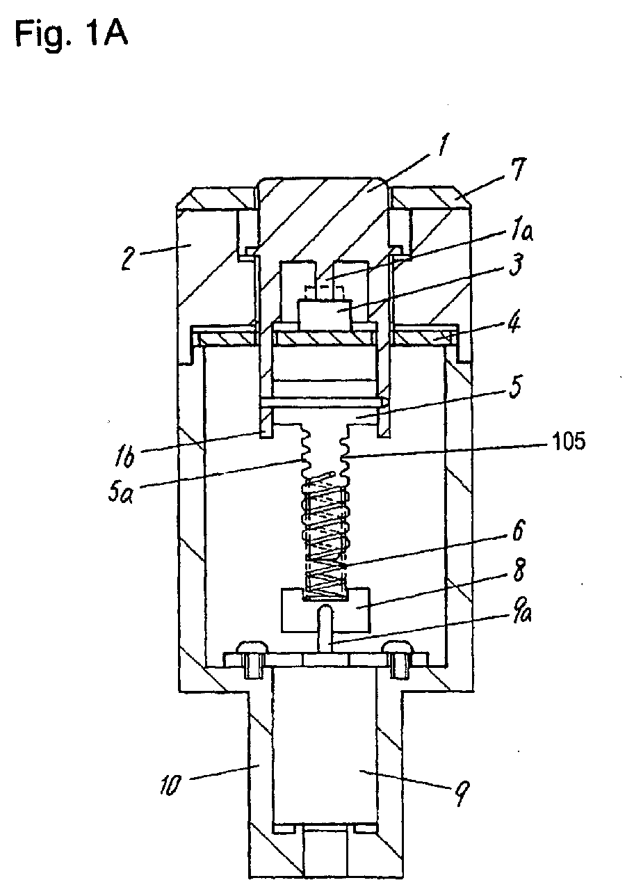
- Figs. 1A and 1B are cross-sectional views of an input device in accordance with Exemplary Embodiment 1 of the present invention.
- Rotation of button 1 is restricted by through-hole 2a provided in case 2, and the button is guided to slide only in up and down directions in the through-hole.
- Button 1 has protrusion 1a at its bottom.
- Push switch 3 is placed on a position of printed board 4 facing protrusion 1a.
- Button 1 has legs 1b at its lower part. Legs 1b extend downward through through-hole 4a provided in printed board 4, and are fixed to driving member 5.
- Driving member 5 has helical part 5a having recess 105 formed therein in a spiral shape of a predetermined pitch.
- Helical part 5a is engaged with coil spring 6 having a pitch identical to the pitch of the recess.
- Button 1 is always pushed up by coil spring 6 with its resilient force.
- Button 1 has brim 1c on its side surface.
- Button 1 moves in through-hole 7a of lid 7 fixed on an upper surface of case 2. Upward movement of button 1 is limited with brim 1c stopped by a lower surface of cover 7.
- Coil spring 6 is fixed to fixing-component 8.
- Fixing-component 8 is fixed to output shaft 9a of motor 9.
- Motor 9 is fixed to base 10.
- Base 10 and case 2 provides a case accommodating aforementioned elements.
- Fig. 1A shows an input device at an ordinary state, in which button 1 projects from an upper surface of cover 7. Upon being pressed down, button 1 moves down along through-hole 2a of case 2 against an upward resiliency of coil spring 6, and then, pushes down switch 3 with protrusion 1a formed at the bottom of the button.
- switch 3 can operate ordinarily, that is, can turn on and off.
- button 1 fixed to driving member 5 shifts and slides downward while being restricted in its rotational movement by through-hole 2a of case 2, and then, button 1 is sunk in through-hole 7a of cover 7.
- the input device in this situation is shown in Fig. 1B.
- button 1 moves down to turn on the switch.
- the device may include another mechanism (not shown) to allow button 1 to turn off the switch when the button moves down
- motor 9 rotates reversely to have the device execute an reverse operation, hence easily allowing the device shown in Fig.1B to return to the device shown in Fig. 1A easily.
- the input device includes a simple structure having spring 6 which allows button 1 to move in up and down directions and allows switch 3 to be turned on and off without a complicated mechanism, such as wheels, belts, and cams.
- Moving speed of button 1 is adjustable by controlling a rotational speed of motor 9, hence preventing a colliding sound of button 1 which is likely to occur, for example, when button 1 is abruptly moved by a solenoid. While button 1 moves down, button 1 is prevented from automatically returning to the status in Fig. 1A even when button 1 receives outside disturbing factors, such as vibration and impact, because button 1 is linked to motor 9 through coil spring 6.
- a length of a portion effective for expansion and contraction of coil spring 6 may be adjusted, and pressing force of button 1 for activating switch 3 can be accordingly controlled arbitrarily
- coil spring 6 In order to slide smoothly, coil spring 6 employ a wire processed to have a friction-reducing surface. The surface reduces a friction caused by coil spring 6 when the spring slides on helical part 5a of driving member 5, hence enabling the spring to be wound smoothly around the helical part. Since frictional wear of coil spring 6 and driving member 5 is reduced, coil spring 6 and driving member 5 have long life.
- Helical part 5a of driving member 5 may be processed to have a reduced-friction surface, and driving member may be processed to have a material having a superior sliding characteristic thereon, hence providing similar effect.
- Fig. 2 is a cross-sectional view of an input device in accordance with Exemplary Embodiment 2 of the present invention.
- Plural slits 11a are formed along a circumference of rotation disk 11 fixed to output shaft 9a of motor 9.
- Photo coupler 12 provided on base 10 surrounds slits 11a.
- Coil spring 6 is fixed to rotation disk 11. When motor 9 rotates, slits 11a of rotating disk 11 open and close an optical path of photo coupler 12.
- the photo coupler detects the opening and closing of the path, hence detecting a rotational amount of coil spring 6, i.e., a moving amount of button 1 in up and down directions.
- rotation disk 11 and photo coupler 12 function as an optical encoder detecting rotation of motor 9. Since the position of moving button 1 in up and down directions is detected and arbitrarily controlled, a projecting amount of button 1 can be controlled.
- Embodiment 2 another type of encoder, such as a magnetic type, an electro-magnetic type, or a resistor type may be used instead of the optical encoder including photo coupler 12, and providing similar effects.
- a magnetic type such as a magnetic type, an electro-magnetic type, or a resistor type
- a resistor type may be used instead of the optical encoder including photo coupler 12, and providing similar effects.
- Fig. 3 is a cross-sectional view of an input device in accordance with Exemplary Embodiment 3 of the present invention.
- Stepping motor 13 is driven by an external control circuit (not illustrated).
- an external control circuit not illustrated.
- a moving amount (a projecting amount) of button 1 can be arbitrarily controlled through an external open loop control with by stepping motor having a required number of pulses supplied thereto.
- Fig. 4 is a cross-sectional view of an input device in accordance with Exemplary Embodiment 4 of the present invention.
- Magnet 14 is attached to leg 1b of button 1 by a method such as of insertion molding and adhesion.
- Plural magnetic sensors 14a and 14b facing magnet 14 are placed on a wall of base 10.
- Magnetic sensor 14a is positioned for sensing a magnetic field of magnet 14 of button 1 in an ordinary state (projecting), and magnetic sensor 14b is positioned for sensing a magnetic field of magnet 14 of button 1 lowered.
- button 1 positioned at its highest position is sensed by magnetic sensor 14a
- button 1 positioned at its lowest position is sensed by magnetic sensor 14b. Therefore, even if motor 9 is an inexpensive DC motor, a highest limit and a lowest limit of button 1 is easily determined by feeding back a signal indicating that button 1 is positioned at its highest position and at its lowest position. Further, magnetic sensors 14a and 14b may generate signals used instead of switch 3, hence eliminating switch 3.
- Fig. 5 is a cross-sectional view of an input device in accordance with Exemplary Embodiment 5 of the present invention.
- Coil spring 6 has unequal-pitch portion 6a having a pitch different from a pitch of helical part 5a.
- a spring constant of portion 6a is set so that button 1 receives a resilient force suitable to activate switch 3.
- Portion 6b of the spring engaged onto helical part 5a of driving member 5 has a pitch equal to the pitch of helical part 5a.
- Fig. 6 is a cross-sectional view of an input device in accordance with a sixth exemplary embodiment of the present invention.
- the same elements as those shown in Fig. 1 according to Embodiment 1 are denoted by the same reference numerals, are not described.
- coil spring 6 When coil spring 6 is wound to pull button 1 and allow the button to contact switch 3, coil spring 6 is elongated by a bouncing load of switch 3 and has its pitch widened. A pitch of tip portion 5b of helical part 5a of driving member 5 is equal to the widened pitch of coil spring 6.
- coil spring 6 is not loaded by switch 3, namely, is not elongated, coil spring 6 is engaged onto helical part 5a while having the pitch widened by elasticity of the coil.
- coil spring 6 When coil spring 6 is loaded by switch 3, coil spring 6 is engaged onto helical part 5a having the pitch identical to the widened pitch of the spring. This arrangement enables the spring to be smoothly wound, hence allowing button 1 to move.
- Fig. 7 is a cross-sectional view of an input device in accordance with Exemplary Embodiment 7 of the present invention.
- the device includes adjustment coil spring 15 placed inside button 1 additionally to coil spring 6 engaged with helical part 5a of driving member 5 attached to button 1.
- Adjustment coil spring 15 pushes button 1 upward, away from printed board 4, namely, away from switch 3.
- Resilient force of adjustment coil spring 15 can be se to a level different from that of coil spring 6.
- An operating force of button 1 for activating switch 3 therefore can be arbitrarily controlled by appropriately controlling the resilient force of coil spring 15.
- Fig. 8 is a cross-sectional view of an input device in accordance with an eighths exemplary embodiment of the present invention.
- the same elements as those shown in Fig. 1 are denoted by the same reference numerals, are not described.
- Tip portion 5d of helical part 5a of driving member 5 which is to have coil spring 6 wound around is tapered by an angle ⁇ .
- Coil spring 6 is easily engaged with driving member 5 even if coil spring 6 and helical portion 5a are not coaxially lined up due to variation of dimensions of components, hence improving reliability of the input device.
- Fig. 9 is a cross-sectional view of an input device in accordance with Exemplary Embodiment 9 of the present invention.
- driving member 55 is fixed to output shaft 59a of motor 9.
- Driving member 55 has helical part 55a having recess 155 formed spirally by a pitch substantially identical to a pitch of coil spring 6.
- Coil spring 6 is fixed on a bottom of button 1 unitarily with button 1.
- the input device is identical to the device according to Embodiment 1 shown in Fig.1, except for driving member 5 and coil spring 6 are placed in a reverse position with each other.
- coil spring 6 is linked directly to driving member 55 fixed to output shaft 59a of motor 9 without an additional component. This arrangement reduces number of components of the input device and simplifies the device.
- a button and a motor is linked by a coil spring.
- the button moves in up and down directions, and a switch is activated with a simple mechanism.
Landscapes
- Physics & Mathematics (AREA)
- General Physics & Mathematics (AREA)
- Engineering & Computer Science (AREA)
- Automation & Control Theory (AREA)
- Push-Button Switches (AREA)
- Mechanisms For Operating Contacts (AREA)
- Switches With Compound Operations (AREA)
Abstract
Description
Claims (11)
- An input device comprising:a button;a case operable to guide the button for allowing the button to slide;a switch fixed to the case and activated with the button;a motor fixed to the case;a driving member fixed to one of the button and the motor;a coil spring fixed to other of the button and the motor, the coil spring being operable to be engaged with the driving member, the coil spring being operable to be rotated to move relatively to the driving member.
- The input device according to claim 1,
wherein the driving member has a helical part having a recess formed spirally, and
wherein the coil spring is operable to be engaged with the helical part and be wound around the helical part. - The input device according to claim 2, wherein the coil spring has a portion having a pitch different from a pitch of another portion of the coil spring.
- The input device according to claim 2, wherein the helical part of the driving member has a portion having a pitch different from a pitch of another portion of the helical part.
- The input device according to claim 2, wherein the coil spring has a low-friction surface.
- The input device according to claim 2, wherein the helical part has a low-friction surface.
- The input device according to claim 2, wherein the helical part of the driving member is tapered at a tip of of the helical part.
- The input device according to claim 1, further comprising an encoder detecting a rotation of the motor.
- The input device according to claim 1, wherein the motor comprises a stepping motor.
- The input device according to claim 1, further comprising a sensor for detecting a movement of the button.
- The input device according to claim 1, further comprising a spring applying a force to urge the button.
Applications Claiming Priority (3)
| Application Number | Priority Date | Filing Date | Title |
|---|---|---|---|
| JP2002364850 | 2002-12-17 | ||
| JP2002364850A JP4063066B2 (en) | 2002-12-17 | 2002-12-17 | Input device |
| PCT/JP2003/015606 WO2004055846A1 (en) | 2002-12-17 | 2003-12-05 | Input device |
Publications (2)
| Publication Number | Publication Date |
|---|---|
| EP1486998A1 true EP1486998A1 (en) | 2004-12-15 |
| EP1486998A4 EP1486998A4 (en) | 2005-03-16 |
Family
ID=32588251
Family Applications (1)
| Application Number | Title | Priority Date | Filing Date |
|---|---|---|---|
| EP03777296A Withdrawn EP1486998A4 (en) | 2002-12-17 | 2003-12-05 | Input device |
Country Status (4)
| Country | Link |
|---|---|
| US (1) | US6919522B2 (en) |
| EP (1) | EP1486998A4 (en) |
| JP (1) | JP4063066B2 (en) |
| WO (1) | WO2004055846A1 (en) |
Cited By (6)
| Publication number | Priority date | Publication date | Assignee | Title |
|---|---|---|---|---|
| FR2889322A1 (en) * | 2005-07-27 | 2007-02-02 | Telecomm Electronique Aeronaut | Pushbutton for use on control console of aircraft, has body having window in its upper surface, and arm comprising two curved ends respectively forming pivot and cursor, where cursor is engaged in channel of slide via window of body |
| EP2835711A1 (en) * | 2013-07-30 | 2015-02-11 | BSH Bosch und Siemens Hausgeräte GmbH | Switching device for a cooking device |
| EP3020896A1 (en) * | 2014-11-12 | 2016-05-18 | Illinois Tool Works Inc. | Push button device with adjustment function for application in a vehicle |
| CN106098424A (en) * | 2016-08-05 | 2016-11-09 | 佛山市威格特电气设备有限公司 | Portable high-pressure opens cabinet safety telecontrol device |
| US10510097B2 (en) | 2011-10-19 | 2019-12-17 | Firstface Co., Ltd. | Activating display and performing additional function in mobile terminal with one-time user input |
| CN110797225A (en) * | 2019-10-22 | 2020-02-14 | 贵州振华华联电子有限公司 | Push-touch electric switch with locking function |
Families Citing this family (18)
| Publication number | Priority date | Publication date | Assignee | Title |
|---|---|---|---|---|
| JP2005116181A (en) * | 2003-10-02 | 2005-04-28 | Toyoda Gosei Co Ltd | Push button |
| JP2006034888A (en) * | 2004-07-30 | 2006-02-09 | Samii Kk | Slot machine |
| JP2006350791A (en) * | 2005-06-17 | 2006-12-28 | Alps Electric Co Ltd | Haptic input device |
| CN101743605B (en) * | 2007-06-22 | 2014-11-05 | 英迪股份有限公司 | Button for electric product |
| JP4737175B2 (en) * | 2007-10-19 | 2011-07-27 | パナソニック電工株式会社 | Switch device |
| US8421608B2 (en) * | 2008-12-23 | 2013-04-16 | Harry B. Lerner | Vibrating trigger button |
| CN102403149B (en) * | 2010-09-10 | 2014-03-26 | 富泰华工业(深圳)有限公司 | Key structure and electronic device with same |
| US9465375B2 (en) * | 2013-03-08 | 2016-10-11 | Volkswagen Ag | Sliding hard keys |
| US10019031B2 (en) | 2015-09-23 | 2018-07-10 | Tdk Taiwan Corp. | Button mechanism |
| KR101600246B1 (en) * | 2015-10-21 | 2016-03-04 | 박정원 | Non-Contact Switch |
| TW201822231A (en) * | 2016-12-08 | 2018-06-16 | 致伸科技股份有限公司 | Input device with adjustable force level |
| JP6262324B1 (en) * | 2016-12-21 | 2018-01-17 | 東芝エレベータ株式会社 | Push button device |
| US10948056B2 (en) * | 2017-12-23 | 2021-03-16 | Continental Automotive Systems, Inc. | Elevation mechanism for a central input selector knob |
| DE102018108847B4 (en) * | 2018-04-13 | 2019-10-31 | Behr-Hella Thermocontrol Gmbh | Operating device for a vehicle |
| CN109686610B (en) * | 2018-11-16 | 2020-10-09 | 安徽三品技术服务有限公司 | Mechanical keyboard shaft with adjustable axle distance |
| CN109552205A (en) * | 2018-12-07 | 2019-04-02 | 北汽福田汽车股份有限公司 | Power switch and vehicle |
| DE102019126321B3 (en) * | 2019-09-30 | 2021-02-04 | Behr-Hella Thermocontrol Gmbh | Control device for a vehicle |
| US11065534B1 (en) | 2020-06-29 | 2021-07-20 | Apple Inc. | Thumbstick user input device and related methods |
Family Cites Families (11)
| Publication number | Priority date | Publication date | Assignee | Title |
|---|---|---|---|---|
| JPS63165723A (en) | 1986-12-26 | 1988-07-09 | Tokyo Electric Co Ltd | Electronic price balance equipped with label printer |
| JPH0438433Y2 (en) * | 1987-04-17 | 1992-09-09 | ||
| JPH0192026A (en) | 1987-10-02 | 1989-04-11 | Nippon Steel Corp | Electric discharge machining method for insulating material |
| JPH0192026U (en) * | 1987-12-09 | 1989-06-16 | ||
| JPH0237627A (en) * | 1988-07-26 | 1990-02-07 | Matsushita Electric Ind Co Ltd | Key switch |
| US5808532A (en) * | 1996-01-24 | 1998-09-15 | Circuit Protection & Controls, Inc. | Motorized module for field assembly to circuit breakers |
| US5838219A (en) * | 1997-05-29 | 1998-11-17 | Eaton Corporation | Electrical circuit breaker with manual and remote actuators |
| US6124709A (en) * | 1998-06-05 | 2000-09-26 | Cts Corporation | Magnetic position sensor having a variable width magnet mounted into a rotating disk and a hall effect sensor |
| JP2001297652A (en) | 1999-04-30 | 2001-10-26 | Yasufumi Mase | Input device having elevating type key top |
| DE19937222C2 (en) * | 1999-08-06 | 2001-11-29 | Webasto Vehicle Sys Int Gmbh | Control device for an electric motor for an adjustable vehicle part |
| DE60200502T2 (en) * | 2001-08-07 | 2005-05-25 | Alps Electric Co., Ltd. | Manual input device with force feedback function |
-
2002
- 2002-12-17 JP JP2002364850A patent/JP4063066B2/en not_active Expired - Fee Related
-
2003
- 2003-12-05 US US10/500,534 patent/US6919522B2/en not_active Expired - Fee Related
- 2003-12-05 WO PCT/JP2003/015606 patent/WO2004055846A1/en not_active Ceased
- 2003-12-05 EP EP03777296A patent/EP1486998A4/en not_active Withdrawn
Cited By (10)
| Publication number | Priority date | Publication date | Assignee | Title |
|---|---|---|---|---|
| FR2889322A1 (en) * | 2005-07-27 | 2007-02-02 | Telecomm Electronique Aeronaut | Pushbutton for use on control console of aircraft, has body having window in its upper surface, and arm comprising two curved ends respectively forming pivot and cursor, where cursor is engaged in channel of slide via window of body |
| US10510097B2 (en) | 2011-10-19 | 2019-12-17 | Firstface Co., Ltd. | Activating display and performing additional function in mobile terminal with one-time user input |
| US10896442B2 (en) | 2011-10-19 | 2021-01-19 | Firstface Co., Ltd. | Activating display and performing additional function in mobile terminal with one-time user input |
| US11551263B2 (en) | 2011-10-19 | 2023-01-10 | Firstface Co., Ltd. | Activating display and performing additional function in mobile terminal with one-time user input |
| US12159299B2 (en) | 2011-10-19 | 2024-12-03 | Firstface Co., Ltd. | Activating display and performing additional function in mobile terminal with one-time user input |
| EP2835711A1 (en) * | 2013-07-30 | 2015-02-11 | BSH Bosch und Siemens Hausgeräte GmbH | Switching device for a cooking device |
| EP3020896A1 (en) * | 2014-11-12 | 2016-05-18 | Illinois Tool Works Inc. | Push button device with adjustment function for application in a vehicle |
| WO2016077069A1 (en) * | 2014-11-12 | 2016-05-19 | Illinois Tool Works Inc. | Push button device with adjustment function for application in a vehicle |
| CN106098424A (en) * | 2016-08-05 | 2016-11-09 | 佛山市威格特电气设备有限公司 | Portable high-pressure opens cabinet safety telecontrol device |
| CN110797225A (en) * | 2019-10-22 | 2020-02-14 | 贵州振华华联电子有限公司 | Push-touch electric switch with locking function |
Also Published As
| Publication number | Publication date |
|---|---|
| US6919522B2 (en) | 2005-07-19 |
| WO2004055846A1 (en) | 2004-07-01 |
| JP2004199922A (en) | 2004-07-15 |
| US20050034965A1 (en) | 2005-02-17 |
| EP1486998A4 (en) | 2005-03-16 |
| JP4063066B2 (en) | 2008-03-19 |
Similar Documents
| Publication | Publication Date | Title |
|---|---|---|
| US6919522B2 (en) | Input device | |
| JP4233978B2 (en) | Bullet ball machine | |
| US5105320A (en) | Operation mode switching and loading-eject mechanism for a tape player | |
| JP2010062075A (en) | Operation feeling imparting type input device | |
| US6789260B2 (en) | Disk drive apparatus | |
| KR100225749B1 (en) | Narrow profile data storage cartridge drive of small overall size | |
| US4309727A (en) | Automatic reverse tape recorder with means for stopping the automatic reverse operation during recording | |
| US4445210A (en) | Tone arm mechanism for a record player | |
| US4635148A (en) | Cassette-receiving door device for cassette tape recorder | |
| US4123015A (en) | Automatic stopping device for tape recorder | |
| US20250006439A1 (en) | Electronic device, push-type input device, and electronic shifter | |
| US20240019888A1 (en) | Push-type input device and push-type shifter device | |
| KR101586798B1 (en) | Inhibitor switch | |
| JPH0512783B2 (en) | ||
| JPH046011Y2 (en) | ||
| JPS6232327Y2 (en) | ||
| US20050076348A1 (en) | Optical disc drive having a disc transport tray moved by a spindle motor | |
| JPS6232321Y2 (en) | ||
| JPS596544Y2 (en) | Record player protection device | |
| CS274491A3 (en) | Recording and/or reproducing apparatus adapted for insertion of a cassette containing a record carrier | |
| KR100194445B1 (en) | Mode change mechanism of tape recorder | |
| JPS6230164Y2 (en) | ||
| JPS6122362B2 (en) | ||
| JPS5990260A (en) | Floppy disk driver | |
| JP4069641B2 (en) | Protective lid opening / closing mechanism of recording / reproducing apparatus |
Legal Events
| Date | Code | Title | Description |
|---|---|---|---|
| PUAI | Public reference made under article 153(3) epc to a published international application that has entered the european phase |
Free format text: ORIGINAL CODE: 0009012 |
|
| 17P | Request for examination filed |
Effective date: 20040820 |
|
| AK | Designated contracting states |
Kind code of ref document: A1 Designated state(s): AT BE BG CH CY CZ DE DK EE ES FI FR GB GR HU IE IT LI LU MC NL PT RO SE SI SK TR |
|
| A4 | Supplementary search report drawn up and despatched |
Effective date: 20050131 |
|
| RBV | Designated contracting states (corrected) |
Designated state(s): DE FR GB IT |
|
| RAP1 | Party data changed (applicant data changed or rights of an application transferred) |
Owner name: PANASONIC CORPORATION |
|
| GRAP | Despatch of communication of intention to grant a patent |
Free format text: ORIGINAL CODE: EPIDOSNIGR1 |
|
| RIN1 | Information on inventor provided before grant (corrected) |
Inventor name: UEHIRA, KIYOTAKA |
|
| STAA | Information on the status of an ep patent application or granted ep patent |
Free format text: STATUS: THE APPLICATION IS DEEMED TO BE WITHDRAWN |
|
| 18D | Application deemed to be withdrawn |
Effective date: 20110907 |