EP1486377A2 - Movable body surrounding monitoring apparatus - Google Patents
Movable body surrounding monitoring apparatus Download PDFInfo
- Publication number
- EP1486377A2 EP1486377A2 EP04012263A EP04012263A EP1486377A2 EP 1486377 A2 EP1486377 A2 EP 1486377A2 EP 04012263 A EP04012263 A EP 04012263A EP 04012263 A EP04012263 A EP 04012263A EP 1486377 A2 EP1486377 A2 EP 1486377A2
- Authority
- EP
- European Patent Office
- Prior art keywords
- movable body
- image
- information
- vehicle
- moving
- Prior art date
- Legal status (The legal status is an assumption and is not a legal conclusion. Google has not performed a legal analysis and makes no representation as to the accuracy of the status listed.)
- Granted
Links
Images








Classifications
-
- B—PERFORMING OPERATIONS; TRANSPORTING
- B60—VEHICLES IN GENERAL
- B60Q—ARRANGEMENT OF SIGNALLING OR LIGHTING DEVICES, THE MOUNTING OR SUPPORTING THEREOF OR CIRCUITS THEREFOR, FOR VEHICLES IN GENERAL
- B60Q9/00—Arrangement or adaptation of signal devices not provided for in one of main groups B60Q1/00 - B60Q7/00, e.g. haptic signalling
- B60Q9/002—Arrangement or adaptation of signal devices not provided for in one of main groups B60Q1/00 - B60Q7/00, e.g. haptic signalling for parking purposes, e.g. for warning the driver that his vehicle has contacted or is about to contact an obstacle
- B60Q9/004—Arrangement or adaptation of signal devices not provided for in one of main groups B60Q1/00 - B60Q7/00, e.g. haptic signalling for parking purposes, e.g. for warning the driver that his vehicle has contacted or is about to contact an obstacle using wave sensors
- B60Q9/005—Arrangement or adaptation of signal devices not provided for in one of main groups B60Q1/00 - B60Q7/00, e.g. haptic signalling for parking purposes, e.g. for warning the driver that his vehicle has contacted or is about to contact an obstacle using wave sensors using a video camera
-
- B—PERFORMING OPERATIONS; TRANSPORTING
- B62—LAND VEHICLES FOR TRAVELLING OTHERWISE THAN ON RAILS
- B62D—MOTOR VEHICLES; TRAILERS
- B62D15/00—Steering not otherwise provided for
- B62D15/02—Steering position indicators ; Steering position determination; Steering aids
- B62D15/029—Steering assistants using warnings or proposing actions to the driver without influencing the steering system
- B62D15/0295—Steering assistants using warnings or proposing actions to the driver without influencing the steering system by overlaying a vehicle path based on present steering angle over an image without processing that image
-
- G—PHYSICS
- G06—COMPUTING OR CALCULATING; COUNTING
- G06T—IMAGE DATA PROCESSING OR GENERATION, IN GENERAL
- G06T7/00—Image analysis
- G06T7/20—Analysis of motion
-
- G—PHYSICS
- G06—COMPUTING OR CALCULATING; COUNTING
- G06V—IMAGE OR VIDEO RECOGNITION OR UNDERSTANDING
- G06V20/00—Scenes; Scene-specific elements
- G06V20/50—Context or environment of the image
- G06V20/56—Context or environment of the image exterior to a vehicle by using sensors mounted on the vehicle
- G06V20/58—Recognition of moving objects or obstacles, e.g. vehicles or pedestrians; Recognition of traffic objects, e.g. traffic signs, traffic lights or roads
- G06V20/586—Recognition of moving objects or obstacles, e.g. vehicles or pedestrians; Recognition of traffic objects, e.g. traffic signs, traffic lights or roads of parking space
Definitions
- the present invention generally relates to a movable body surrounding monitoring apparatus for monitoring circumstance of a movable body. More particularly, the present invention pertains to a movable body surrounding monitoring apparatus for monitoring a environment around the movable body and displaying an image of a view from the movable body positioned at an intended position.
- the present invention pertains to a movable body surrounding monitoring apparatus being preferable for monitoring an environment around a vehicle and for displaying an object which can be an obstacle upon vehicle parking.
- Such apparatus includes, for example, a camera at a vehicle rear side, which monitors the environment behind the vehicle, and a monitor being installed near a driver's seat, which displays an image of the environment behind the vehicle shot by the camera.
- a garaging assist system for automobile for example, is disclosed in a Japanese Patent Laid-open published as No. 1987-278477.
- the garaging assist system for automobile includes a computer for calculating an automobile driving track based upon signals outputted from a distance sensor and a steering wheel angle sensor.
- a user mainly the driver
- the rear sight display unit for the vehicle includes obstacle detecting sensors set at front left and front right portions of the vehicle for detecting the vehicle front sides approaching to obstacles. The detected information is displayed with the rear sight in a monitor window at the same time. Therefore, the vehicle backward operation by the driver can be performed without causing the vehicle front left and front right portions to become in contact with the obstacles even if the driver's visual line is not shifted from the monitor display plane to the vehicle forward.
- the parking support system includes a single camera for image capturing surroundings of a moving vehicle at first and second points, an imaging unit for converting the surroundings of the moving vehicle into first and second images which are produced in time series, a stereoscopic object-specifying unit for detecting and specifying a stereoscopic object in each image, a vehicle position calculating unit for calculating a vehicle moving data from the first point to the second positions, and a stereoscopic object distance calculating unit for calculating a distance between the vehicle and the stereoscopic object based upon the positions of the stereoscopic object in the first and second images and the vehicle moving data.
- the parking support system including the above structure generates a third image for instructing the driver based upon the images by the imaging unit and the distance between the vehicle and the stereoscopic object calculated by the stereoscopic object distance calculating unit. Therefore, an accurate distance between the vehicle and the stereoscopic object can be calculated in accordance with principles of triangulation modes with the stereoscopic object in the first and second images.
- a relative position detection device and a parking auxiliary apparatus furnished with the relative position detection device in a Japanese Patent Laid-open published as No. 2002-052999.
- an own vehicle stop position marker and a lateral direction measuring marker are superposed and displayed in a monitor window. Therefore, a position of the own vehicle relative to a reference object can be detected by use of the camera image and a general steering wheel angle sensor without using a gauge sensor.
- the own vehicle stop position marker is defined as a marker for stopping the own vehicle in a positional relation that the own vehicle and the reference object are positioned possessing a predetermined orientation.
- the lateral direction measuring marker is defined as a marker for measuring a lateral distance between the own vehicle and the reference object in response to a vehicle moving amount in the monitor window.
- a stereo vision is defined as a method of calculating a three-dimensional shape of a substance in accordance with principles of triangulation modes based upon a corresponding relation between the images shot by two cameras.
- the stereo vision is further defined as one of the most fundamental methods of extracting a three-dimensional information from images so as to be used for a robot control.
- the view at a rear side of the vehicle can be shot by the camera and be displayed in the monitor. Therefore, the vehicle can be moved rearward or parked observing the obstacle behind the vehicle displayed in the monitor.
- the environment around the vehicle comer is out of the view shot by the camera, so that the environment cannot be displayed in the monitor. In this case, when the vehicle is moved rearward while turning for example, the driver cannot recognize whether or not there is a sufficient distance between a turning inside of the own vehicle comer and an obstacle such as the other vehicle.
- a camera possessing an appropriate camera angle can be projected from the vehicle so as to encompass the corner portion of the own vehicle in the camera shot view.
- this type of arrangement of the camera on the vehicle may spoil a vehicle design, thereby not being appropriate for all types of vehicles.
- the camera can be mounted near the vehicle comer.
- a lighting unit is usually disposed around the vehicle comer.
- the camera is required to be sufficiently heat-resistant or a surface cover of the lighting unit is required to be made of optical materials for the camera such that image quality is not spoiled.
- technical and cost problems still remain. Even if the camera can be assembled in the lighting unit, the road immediately below a vehicle bumper may not be able to be shot by the camera due to a projected portion of the vehicle bumper.
- an image A shot while the vehicle 1 is at a position a is converted to an image as if it were shot while the vehicle 1 was at a position b, wherein an image C can be calculated.
- a distance between the vehicle and a stereoscopic object can be geometrically calculated based upon a deviation between the two images and the vehicle moving data.
- the Patent document 3 does not make a contribution to the above-described drawback.
- any of abovementioned apparatuses is not functioned preferably when the moving obstacle exists in an image shot by the camera.
- the moving obstacle is considered as still being in the virtual image even though the moving obstacle has been already out of the view shot by the camera, and not existed in the shot image at that time.
- the moving obstacle in the image shot by the camera should be detected, furthermore, the detected moving obstacle should be controlled, for example, not to display the virtual image and the like.
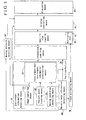
- a movable body surrounding monitoring apparatus characterized in that the apparatus includes an environment information detecting means (SR) for detecting and storing information about an environment around a movable body, a movable body information detecting means (MB) for detecting and storing position and posture of the movable body, an information combining means (CB) for combining the information detected by the movable body information detecting means (MB) and the information detected by the environment information detecting means (SR), correcting a relative relationship of position and posture between the movable body and the environment around the movable body, and outputting information of such relative relationship, a specific view creating means (SV) for creating a specific view of the movable body with reference to information of the environment around the movable body at a specific position based on the information outputted from the information combining means (CB), a displaying means (VD) for displaying the specific view created by the specific view creating means (SV) as an image, a moving obstacle detecting means (MO
- a movable body surrounding monitoring apparatus is mounted on a vehicle illustrated in FIG. 4 and is applied to a parking asist system.
- the movable body surrounding monitoring apparatus is provided with a environment information detecting means SR for detecting and storing information of environment surrounding the movable body, such as size and position of an object around the movable body, and a movable body information detecting means MB for consecutively detecting and storing position and posture of the movable body.
- the movable body information detecting means MB can be configured with a sensor for detecting vehicle dynamic condition such as a vehicle driving speed, a vehicle steering condition, and a vehicle turning condition.
- a coordinate depicting a vehicle position and an angle depicting a vehicle posture can be detected based upon at least a signal outputted from a sensor, which will be described later.
- the environment information detecting means SR includes an image capturing means CD mounted on the movable body for obtaining an image of the environment abound the movable body and for outputting the image information, a feature point tracking means PF for detecting a coordinate of a feature point in a first image at a first state of the movable body and a coordinate in a second image at a second state of the movable body, which corresponding to the feature point in the first image, based on at least two images which are the first image at the first state of the movable body and the second image at the second state thereof when the movable body moves from the first state to the second state, a moving condition detecting means DS for detecting the position and posture of the movable body at least at the first and the second states, and a three-dimensional environment information constructing means RC for constructing environment information by estimating a three dimensional coordinate of the feature point based upon the position and posture of the movable body at the first and second states detected by the moving condition
- the moving condition detecting means DS may be various types of sensors for detecting, such as a vehicle speed, steering angle and rotating condition. Furthermore, the moving condition detecting means DS may use information of the movable body detected at the movable body information detecting means MB.
- the image capturing means CD may be use a CCD camera.
- the movable body surrounding monitoring apparatus is further provided with an information combining means CB, a specific view creating means SV, and a displaying means VD.
- the information combining means CB combines the movable body information detected by the movable body information detecting means MB and the information of the environment surrounding the movable body detected by the environment information detecting means SR, and corrects a relation of the position and posture of the movable body relative to the environment surrounding the movable body.
- the specific view creating means SV creates a specific view of the movable body with reference to the information of the environment surrounding the movable body located at a specific position based upon the positional and postural relation of the movable body relative to the surrounding environment outputted from the information combining means CB.
- the displaying means VD displays a image of the specific view created by the specific view creating means SV.
- the displaying means VD can be represented such as a display monitor (not shown) installed in a movable body.
- the movable body surrounding monitoring apparatus is further includes a moving obstacle detecting means MO for detecting a obstacle moving around the movable body based on the detected information at the environment information detecting means SR and a display controlling means VC for controlling an image displaying of a specific view on the displaying means VD based on the obstacle detected by the moving obstacle detecting means MO.
- the moving obstacle detecting means MO is configured for detecting the moving obstacle from the image shot by the image capturing means CD
- the display controlling means VC is configured for controlling (even prohibiting) displaying the image of the specific view by the displaying means VD if a predetermined condition is fulfilled after the moving obstacle is detected by the moving obstacle detecting means MO.
- the aforementioned predetermined condition may be at least one of following three conditions; (1) a time equal to or more than a predetermined time pasts after the moving obstacle disappears from the image shot by the image capturing means CD, (2) the movable body is moved equal to or more than a predetermined distance, or (3) the moving obstacle rotates equal to or more than a predetermined angle.
- the moving obstacle detecting means MO detects the moving obstacle by detecting a differential between the first image at the first state and the second image at the second state shot by the image capturing means CD using at least one of arithmetical operation or logical operation.
- the moving obstacle detecting means MO detects the moving obstacle by detecting a differential between an estimated second image at the second state based on the first image at the first state and the detected information at the movable body information detecting means MB, and the second image at the second state using at least one of arithmetical operation or logical operation.
- the configuration of the moving obstacle detecting means MO will be described later in detail in reference to FIG13 and FIG.14.
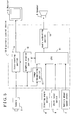
- a movable body surrounding monitoring apparatus is mounted, for example on the vehicle 1 illustrated in FIG. 4 and is applied to the parking asist system.
- the movable body surrounding monitoring apparatus is provided with an instruction inputting means SE in addition to the structure illustrated in FIG. 1.
- a switching means CH is included in the specific view creating means SV. Operation of the switching mans CH switches the specific view created by the specific view creating means SV to a view selected based upon the driver's instruction inputted by the instruction inputting means SE.
- the display controlling means VC controls so as to restrict (e.g.
- the instruction inputting means SE inputs an instruction reflecting a vehicle driver's intention regarding a specific view.
- a mechanical switch may be used as the instruction inputting means SE.
- the display monitor (not shown) is used as the displaying means VD, a touch panel on a display screen of the monitor may be used as the instruction inputting means SE.
- a voice recognition equipment may be applied as the instruction inputting means SE.
- the image displayed by the displaying means VD based on the output from the specific view creating means SV can be constructed with a predetermined image and other images which may have been enlarged, diminished, rotated, shot from a different viewpoint, or the like.
- a movable body surrounding monitoring apparatus is mounted, for example on the vehicle 1 illustrated in FIG. 4 and is applied as the parking asist system.
- the movable body surrounding monitoring apparatus is provided with a track estimating means TR in addition to a structure illustrated in FIG. 1.
- the track estimating means TR estimates a moving track of the movable body based upon the information detected by the movable body information detecting means MB.
- the specific view creating means SV includes an overlapping means OL for overlapping an expected moving track of the movable body estimated by the track estimating means TR on the specific view.
- the displaying means VD displays an image in which the estimated moving track has been overlapped on the specific view.
- the display controlling means VC controls image displaying of a specific view by the displaying means VD.
- An estimated vehicle driving track can be applied, for example, as the estimated moving track by the track estimating means TR, which will be described later with reference to FIGS. 25 through 27.
- a camera 2 e.g. a CCD camera
- the image capturing means CD is mounted at a rear portion of the vehicle 1 so as to obtain an image of the environment around there.
- the image information obtained by the camera 2 is provided to an electronic control unit 10.
- the electronic control unit 10 is housed in a container mounted on the vehicle 1 and acts as the moving condition detecting means DS, the movable body information detecting means MB, the three-dimensional environment information constructing means RC, the information combining means CB, the specific view creating means SV, the moving obstacle detecting means MO, the display controlling means VC, the switching means CH, the overlapping means OL and the track estimating means TR.
- a steering angle sensor 4 is disposed in the vehicle 1 so as to detect a steering angle of a steering wheel 3.
- a shift lever switch 6 is disposed in the vehicle 1, which is turned on when a shift lever 5 is shifted to a reverse stage. The detected steering angle and the on signal are then provided to the electronic control unit 10, respectively.
- vehicle wheel speed sensors 7 are mounted on respective vehicle wheels so as to detect rotational speed of the respective corresponding vehicle wheels.
- the detected vehicle wheel speed is supplied to the electronic control unit 10. Accordingly, a moving distance of the movable body at least between a first position and a second position can be gauged based upon the detection result of the vehicle wheel speed sensors 7.
- a monitor 8 is arranged at a predetermined position in the vehicle 1 and should be easily visible by the driver.
- the monitor 8 displays visual information for parking guiding in response to output signals from the electronic control unit 10. That is, according to the embodiments of the present invention, the monitor 8 acts as the displaying means VD explained in FIGs. 1 through 3. Further, a speaker 9 is disposed at a predetermined position in the vehicle 1, thereby enabling to output audio information for parking guiding in response to an output signal from the electronic control unit 10.
- the steering angle sensor 4, the shift lever switch 6, and the vehicle wheel speed sensors 7 are connected to a CPU 11 in the electronic control unit 10 via an input interface (not shown).
- the monitor 8 is connected to a superimposing portion 14 in the electronic control unit 10 via an output interface (not shown).
- the speaker 9 is connected to the CPU 11 via an audio outputting portion 15.
- the camera 2 is connected to an image recognizing portion 12, a graphics drawing portion 13, and the superimposing portion 14 via the input interface.
- the CPU 11, the image recognizing portion 12, the graphics drawing portion 13, a superimposing portion 14, and an audio outputting portion 15 are connected by bus bars, respectively. Information in each module is stored for a predetermined period of time and can be read out when needed.
- the information of the image of the environment surrounding the vehicle 1 shot by the camera 2 is supplied to the CPU 11 for calculation via the image recognizing portion 12.
- the signal outputted from the vehicle wheel speed sensors 7 and so on are also supplied to the CPU 11 for the calculation.
- the graphics drawing portion 13 draws a three-dimensional graphics in response to a synchronization signal extracted from the image shot by the camera 2 based upon the calculated result. In the meantime, calculation is performed by the CPU 11 for the purpose of the parking assistance.
- a graphics based upon the calculation result is drawn by the graphics drawing portion 13.
- the graphics drawn by the graphics drawing portion 13 and the image shot by the camera 2 are superposed by the super imposing portion 14 when needed and are displayed in the window screen of the monitor 8.
- the three-dimensional environment information constructing means RC, the information combining means CB, the specific view creating means SV, and the display controlling means VC are configured with the CPU 11, the image recognizing portion 12, and the graphics drawing portion 13.
- the feature point tracking means PF detects the coordinate of the feature point in the image shot at the first state by the camera 2 and also detects the coordinate, which corresponds to the feature point, in the image shot at the second state by the camera 2.
- the moving condition detecting means DS detects the positions and postures of the movable body at least at the first and second states, respectively.
- the three-dimensional environment information constructing means RC reconstructs a three-dimensional shape based upon the positions and postures of the movable body at the first and second states, the coordinate of the feature point in the image shot at the first state by the camera 2, and the coordinate, which corresponds to the feature point, in the image shot at the second state by the camera 2, wherein a three-dimensional coordinate of the feature point can be obtained.
- FIG. 6 when observing an identical point M in the space at least from two camera positions, as shown as o and o' on the left and right sides in FIG. 6, light rays in the air connecting the optical center of the camera and points m 1 and m 2 observed in the images shot by the respective cameras can be determined. An intersecting point of both light rays represents the point M in the space. In this case, the three-dimensional point M in a scene of interest needs to be identified between the images.
- a corresponding stereo can be applied to determine at which position and posture of the camera each time-serial image was shot, as far as the correspondences have been calibrated by a dead-reckoning system.
- Detection of the feature point in the scene of interest can be carried out by detecting some feature points which characterize the object in the scene of interest.
- the feature points in this case correspond to points possessing appropriate characteristics which are traceable along with the processing sequence of the image.
- An automatic correlation shown as formula 1 discussed below can be applied for detecting the feature points.
- a matrix A functions to average derivatives of the image signal included in a window region W containing a point p (x, y) in the image.
- an optimal feature point can be obtained by using the matrix A. That is, the feature point suitable for the tracking generally corresponds to a corner and an intersecting point of lines (e.g., a block dot at a corner of the left side of the drawing in Fig.
- I (x, y) shows a function of the image
- I x shows a gradient of the image relative to an x-axis
- I y shows a gradient of the image relative to a y-axis
- (x k , y k ) shows an image point in the window W having (x, y) as a centre of the image.
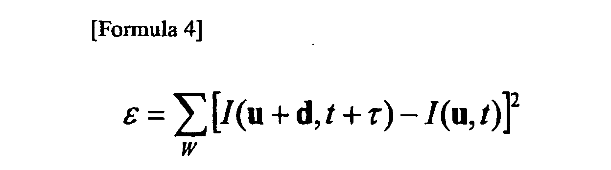
- the displacement vector d may be calculated by a sum of square difference.
- the displacement vector d which minimizes a residual of the formula 4, is obtained and the feature points are tracked in the direction of the displacement vector d as illustrated in FIG. 7.
- "W" of the formula 4 represents a window for detecting the feature points with reference to the point u.
- a track is a set of points characterising an identical object among the image sequences.
- Image points of each track correspond to projections of respective three-dimensional points.
- the tracks of an image sequence should not be lost, the tracking has to be stopped when the tracking points cannot be detected because the points to be tracked are out of the image or are hidden, or due to noise.
- the feature points of the previous image i.e., Img A in Fig. 8
- the next image i.e., Img B in Fig. 8.
- new feature points are searched in the Img B and the new feature points are referred to as starting points for the tracking thereafter.
- the second camera coordinate system can be produced by giving rotation matrix R and translation vector T to the first camera coordinate system with a central focus on the original viewpoint o.
- the translation vector T is referred to as a baseline vector.
- the parameters ⁇ T, R ⁇ depict a relative positional and postural relationship between these two camera viewpoints. Therefore, when the object is shot by a single camera, the camera movement such as translation and rotation can be measured by the dead reckoning system.
- the projections of the position M in the three-dimensional space are assumed to be positioned at the coordinates m 1 and m 2 in each image.
- the direction of the feature point from the viewpoint o' of the second camera coordinate system is depicted with a vector m 2 with respect to the second camera coordinate.
- the second camera coordinate was produced by giving rotation matrix R to the first camera coordinate system. Therefore, the direction of the feature point from the viewpoint o' is depicted with Rm 2 with respect to the first camera coordinate system, wherein formula 6 is obtained.
- the distances Z and Z' in the three-dimensional space can be restored depending on the coordinates m 1 and m 2 of the projections onto the respective images from the two different camera viewpoints.
- the aforementioned track is the set of points in the target view. Therefore, the three-dimensional shape can be restored based upon the calculation in accordance with the formula 7 regarding all tracks.
- both images may be exactly the same if there is no moving obstacle (a human body in FIG.9) in the target view (scene, landscape), however, both images may be differ as shown in FIG.9 (C) if the moving obstacle exists in the target view. Focusing on residual obtained by arithmetical operation and logical operation of the two images. When there is no moving obstacle, the residual will be zero, on the other hand, when moving obstacle exists in the view, a value corresponding to the size and moving speed of the object (obstacle) can be obtained.
- the existence of the moving obstacle (a human body in Fig.9) can be determined through aforementioned processes when the image capturing means CD (camera 2) is in static state, in other word, the vehicle 1 where the camera 2 is mounted is in static state, however, the moving obstacle cannot be detected properly when the vehicle 1 is moving because it is difficult to detect the moving obstacle from the target view (landscape) in which all elements in the shot image is moved along with the movement of the vehicle 1.
- the movable body surrounding monitoring apparatus uses the aforementioned means for reconstructing a three-dimensional shape based upon the position and posture of the movable body.
- a moving obstacle human body in FIGs.10
- the images shot by the camera 2 is used for detecting the moving obstacle in the target view (landscape), however, the moving obstacle can be detected in the same manner using a supersonic type sensor, an optical sensor and an electric wave sensor.
- a supersonic type sensor an optical sensor
- an electric wave sensor an electric wave sensor
- the dead reckoning system as the moving condition detecting means DS for detecting the moving state of the vehicle can be configured with at least one sensor for detecting the vehicle dynamic state such as the vehicle running speed, the steering condition, the vehicle turning condition and the like.
- the dead reckoning system can be configured with the vehicle wheel speed sensor 7 and can be applied as the movable body information detecting means MB.
- the object (obstacle in static condition or movable condition) existing in the imaged region can be specified based upon the vehicle positions and postures at the first and second conditions, and the corresponding points identified between the specified images by extracting and tracking the feature points in the images shot by the camera 2 at the first and second conditions, wherein the three-dimensional coordinate in the imaged region can be estimated.
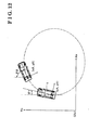
- the dead-reckoning system is constructed for detecting the vehicle state, i.e. the position and the direction (i.e., angle about the vertical axis) of the vehicle 1, based on the wheel speed signals detected by the vehicle wheel speed sensors 7.
- the movable body information detecting means MB is configured with the dead reckoning system.
- the position and the direction of the vehicle 1 may be defined with three variables (x, y, ⁇ ).
- the vehicle speed is defined as a vehicle speed V
- the angular velocity of the vehicle 1 is defined as an angular velocity ⁇
- V (Vrr + Vr1) / 2
- ⁇ (Vrr -Vr1) / Lt
- Vrr stands for the wheel speed of the rear right wheel
- Vrl stands for the wheel speed of the rear left wheel
- Lt stands for a tread length of the vehicle.
- the vehicle state (x, y, ⁇ ) at a time t can be shown in the following manner when an initial value (x 0 , y 0 , ⁇ 0 ) when t equals to zero is determined.
- the vehicle state (x, y, ⁇ ) will be determined as shown in a formula 8.
- the positional relationship from a first vehicle condition determined by a first position (i.e., coordinates (x 1 , y 1 )) and a first direction (i.e., angle ⁇ 1 ) to a second vehicle condition determined by a second position (i.e., coordinates (x 2 , y 2 )) and a second direction (i.e., angle ⁇ 2 ) can thus be determined.
- the vehicle position i.e., coordinates
- the direction i.e., angle
- the position and direction of the vehicle 1 may be determined by use of the steering angle sensor 4, a yaw rate sensor (not shown), a distance sensor (not shown), or combinations of those.
- FIG. 12 shows the plain circle turning movement of the vehicle 1, the vehicle movement can be tracked in accordance with combination of plural arcs or direct lines based upon the above-described coordinates and directions of the vehicle 1.
- the three-dimensional environment estimated by the three-dimensional environment information constructing means RC is stored in a memory as a three-dimensional map denoted with broken lines with reference to the three-dimensional coordinates (X, Y, Z).
- the other vehicles which are not the own vehicle and shot by the camera 2, the obstacles, the buildings which are shot by the camera 2, and the like in the three-dimensional map.
- Three-dimensional maps are denoted with broke lines in FIGS. 14 through 18 as well.
- the three-dimensional coordinate in FIG. 12 is corresponded relative to the three-dimensional map. That is, the relative positional and postural relationship of the vehicle 1 to the surrounding environment is corrected by the information combining means CB.
- the vehicle 1 illustrated in FIG. 12 is positioned in the three-dimensional map denoted with the broken lines in FIG. 13. Therefore, the position (coordinate) of the vehicle 1 and the posture, i.e. the direction (angle) of the vehicle 1 are specified in the three-dimensional map.
- the specified view is created by the specified view creating means SV when a camera is assumed to have been oriented in a predetermined direction on the vehicle 1 positioned at a predetermined point in the third-dimensional environment containing the environment around the vehicle 1.
- An image of the view shot by this virtual camera is displayed in the monitor 8 as the displaying means VD.
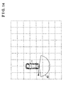
- FIG. 14 shows which region is contained in a view shot by the virtual camera 2a in accordance with the third-dimensional map with the vehicle 1 after moving.
- a region denoted with Sa in FIG. 14 is contained in the view shot by the virtual camera 2 and is displayed as a virtual image in the monitor 8.
- the region displayed in the monitor 8 is referred to as a displayed view.
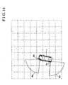
- FIG. 15 shows displayed views Sb and Sc contained in views shot by a virtual camera 2b mounted at a front left comer of the vehicle 1 and by a virtual camera 2c mounted at a rear left corner thereof in accordance with the third-dimensional map with the vehicle 1 after moving.
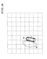
- FIG. 16 shows a displayed view Sd contained in a view shot by a virtual camera 2d in accordance with the third-dimensional map with the vehicle 1 after moving.
- the angles shot by the cameras illustrated in FIGS. 14, 15, and 16 are designed to be substantially similar to the angle shot by the actual camera 2.
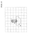
- a virtual camera 2e can be mounted on the vehicle 1 so as to set a displayed view Se at 180 degrees. Therefore, the monitor 8 can display a virtual image which also contains views around the left and right corners which cannot be shot by the actual camera 2.
- a virtual camera 2f can be mounted above the vehicle 1 so as to set a displayed view Sf at 360 degrees. The monitor 8 can display a virtual image containing this view shot by the virtual camera 2f.
- the monitor 8 can display a virtual image containing the obstacle shot during the vehicle 1 is moving when needed. For example, as illustrated in FIG. 19, when the vehicle 1 is located at a position denoted with double dashed lines, the obstacle OB being in static state appears in a region Sp denoted with double dashed lines, wherein the monitor 8 displays an image containing the obstacle OB.
- the obstacle OB disappears in a region Sn denoted with a solid line, wherein the displayed image in the monitor 8 does not contain the obstacle OB.
- the obstacle OB approaches to a portion between the rear left comer of the vehicle 1 and the front left thereof. In this case, the obstacle OB deviates from a view which can be shot by the camera 2, wherein the monitor 8 may not display the obstacle approaching to the vehicle 1.
- the displayed image can contain both comers of the vehicle 1 as illustrated in FIGS. 20 and 21.
- a relative position of the obstacle OB being in static state to the vehicle 1 is shifted in an arrow direction illustrated in FIG. 21 from the position denoted with the double dashed lines.
- the obstacle OB is then illustrated with a solid line. As described above, even if the obstacle OB deviates from an actual view shot by the actual camera 2, the driver can recognize the position of the obstacle OB through the screen of the monitor 8.
- the instruction inputting means SE and the switching means CH switches an image to be displayed in the monitor 8 between the image actually shot by the actual camera 2 and a virtual image such as the images illustrated in FIGS. 20 and 21.
- the monitor 8 possesses a displayed screen (A) which shows not only the image (not shown) of the rear view of the vehicle 1 but also touch panel switches indicating "Left corner" and "Right corner".
- the displayed screen (A) is switched to a screen (B) which zooms the left comer of the vehicle 1.
- the driver can easily recognize the obstacle OB approaching to the left comer of the vehicle 1.
- the portion of the vehicle 1 is zoomed in the monitor 8 as the driver intends.
- the display illustrated in FIG. 20 can be moved from side to side or can be auditorily warned about the obstacle OB approaching to the vehicle 1.
- the movable body surrounding monitoring apparatus is controlled in at least one of following ways based on the aforementioned predetermined conditions.
- the movable body surrounding monitoring apparatus is controlled in at least one of following ways based on the aforementioned predetermined conditions.
- the virtual image may be switched to an actual image shot by the second camera.
- the obstacle OB around the vehicle 1 can be recognized by the user, especially by the driver, in a three-dimensional environment.
- the monitor 8 can automatically display environments outside the view by the camera 2 as a virtual image. For example, as illustrated in FIG. 23, when the vehicle 1 is parallel parked at the left-hand side of the road, the vehicle 1 is moved rearward and turned in an arrow direction, i.e. in a counterclockwise direction. In this case, the other vehicle OV approaching to the vehicle 1 within the predetermined distance can be recognized as a moving obstacle.
- the specific view can be created by the specific view creating means SV so as to contain the vehicle OV.
- a virtual image including a front left comer portion of the vehicle 1 can be displayed or switchably selected in the monitor 8 as illustrated in FIG. 24 automatically or following the driver's intention.
- the surrounding environment including the other vehicle OV is actually shot by the camera 2 when the vehicle 1 is moved rearward for the parallel parking after forward moving in a region illustrated in FIG. 23.
- the information of the surrounding environment including the other vehicle OV has been stored as a third-dimensional environment map in the memory (not shown). Therefore, the position (coordinate) and posture (direction) of the vehicle 1 can be specified in the three-dimensional environment map.
- the virtual image shown in FIG. 24 can be automatically displayed in the monitor 8.
- the virtual image is switched to the actual image.
- the driver also can be auditorily warned instead of display in the monitor 8.
- a warning notice can be displayed in the monitor 8 with some alarm.
- other obstacle such as the other vehicle OV is detected to be located within a region at a predetermined distance away from the own vehicle, a virtual image containing the obstacle can be automatically displayed in the monitor 8. The driver can be auditorily alarmed at the same time as the display in the monitor 8.
- the movable body surrounding monitoring apparatus includes the track estimating means TR for estimating the moving track of the movable body based upon the information detected by the movable body information detecting means MB.
- the specific view creating means SV is provided with the overlapping means OL for overlapping the moving track estimated by the track estimating means TR onto the specific view. For example, when the vehicle 1 is parallel parked at the right-hand side on the road as illustrated in FIGS. 25 through 27, the overlapping means OL overlaps a recommended course for parking asist RC and an expected moving track EC of the vehicle 1. These overlapped images can be displayed as a virtual image in the monitor 8.
- the expected moving track EC of the vehicle 1 for the vehicle rearward movement can be calculated based upon an information representing the vehicle operation condition such as the steering angle detected by the steering angle sensor 4 illustrated in FIG. 5.
- the calculation of the expected moving track EC can be calculated in accordance with a known method for a conventional parking asist such that the description will be omitted hereinafter.
- FIGS. 25, 26, and 27 show a parking space PS, respectively.
- the monitor 8 can display the virtual image in the region illustrated in each FIG. 25, 26, and 27 when the vehicle 1 is further moving rearward.
- the obstacle such as a vehicle within an area shown in FIG.25 through FIG.27 moves and is determined as a moving obstacle being (by the moving obstacle detecting means MO), and the aforementioned predetermined condition is fulfilled, the virtual images shown in FIG.25 through FIG.27 can be switched to the actual images.
- the virtual image is switched to the actual image.
- the image is displayed preferably, not continuously displaying the virtual image of the obstacle before it moves.
- the virtual image can be displayed in the monitor 8 by use of the single camera 2. Therefore, the camera does not have to be mounted at a portion such as a vehicle comer which may not be preferable from a technical or designing point of view. Further, a desired virtual image can be displayed in the monitor 8 when needed based upon the information of the environment surrounding the vehicle 1 actually shot by the camera 2, independently from the position and orientation of the camera 2 mounted on the vehicle 1.
- the camera 2 mounted at the rear portion of the vehicle 1 illustrated in FIG. 4 is applied as the image capturing means CD.
- a camera which is mounted at a side portion of the vehicle 1 or a front portion thereof can be applied as the image capturing means CD.
Landscapes
- Engineering & Computer Science (AREA)
- Multimedia (AREA)
- Transportation (AREA)
- General Physics & Mathematics (AREA)
- Theoretical Computer Science (AREA)
- Mechanical Engineering (AREA)
- Physics & Mathematics (AREA)
- Human Computer Interaction (AREA)
- Remote Sensing (AREA)
- Radar, Positioning & Navigation (AREA)
- Chemical & Material Sciences (AREA)
- Combustion & Propulsion (AREA)
- Computer Vision & Pattern Recognition (AREA)
- Closed-Circuit Television Systems (AREA)
- Length Measuring Devices By Optical Means (AREA)
- Image Processing (AREA)
- Control Of Position, Course, Altitude, Or Attitude Of Moving Bodies (AREA)
Abstract
Description


Claims (10)
- A movable body surrounding monitoring apparatus characterized in that the apparatus comprises:an environment information detecting means (SR) for detecting and storing information about an environment around a movable body;a movable body information detecting means (MB) for detecting and storing position and posture of the movable body;an information combining means (CB) for combining the information detected by the movable body information detecting means (MB) and the information detected by the environment information detecting means (SR), correcting a relative relationship of position and posture between the movable body and the environment around the movable body, and outputting information of such relative relationship;a specific view creating means (SV) for creating a specific view of the movable body with reference to information of the environment around the movable body at a specific position based on the information outputted from the information combining means (CB); a displaying means (VD) for displaying the specific view created by the specific view creating means (SV) as an image;a moving obstacle detecting means (MO) for detecting an obstacle movable around the movable body based on the information detected by the environment information detecting means (SR); anda display controlling means (VC) for controlling displaying the specific view at the displaying means (VD) based on the detected result by the moving obstacle detecting means (MO).
- A movable body surrounding monitoring apparatus according to claim 1, wherein the display controlling means (VC) controls displaying the specific view on the displaying means (VD) when a predetermined condition is fulfilled after the moving obstacle detecting means (MO) detects the moving obstacle.
- A movable body surrounding monitoring apparatus according to claim 1, wherein the environment information detecting means (SR) includes:at least one image capturing means (CD) mounted on the movable body for obtaining an image of the environment around the movable body and for outputting such image, and the image capturing means obtaining at lease two images shot at a first state and at a second state of the movable body when the movable body moves from the first state to the second state;a feature point tracking means (PF) for detecting a coordinate of a feature point in the first image at the first state of the movable body and a coordinate in the second image at the second state corresponding to the feature point in the first image at the first state;a moving condition detecting means (DS) for detecting position and posture of the movable body at least at the first and second states; anda three-dimensional environment information constructing means (RC) for constructing a three-dimensional environment information of the feature point based upon the position and posture of the movable body at the first and second states detected by the moving condition detecting means (DS), the coordinate of the feature point in the image at the first state of the movable body and the coordinate in the second image at the second state corresponding to the feature point in the first image at the first state.
- A movable body surrounding monitoring apparatus according to claim 3, wherein the moving obstacle detecting means (MO) detects the moving obstacle in an image shot by the image capturing means (CD), and the display controlling means (VC) controls displaying the image of the specific view at the displaying means (VD) when a predetermined condition is fulfilled after the moving obstacle detecting means (MO) detects the moving obstacle.
- A movable body surrounding monitoring apparatus according to claim 4, wherein the display controlling means (VC) controls displaying the image of the specific view at the displaying means (VD) when at least one of following conditions is true:(1) a time a equal to or more than a predetermined time pasts after the moving obstacle disappears from the image shot by the image capturing means (CD);(2) the movable body is moved equal to or more than a predetermined distance, and(3) the moving obstacle rotates equal to or more than a predetermined angle.
- A movable body surrounding monitoring apparatus according to claims 3 through 5, wherein the moving obstacle detecting means (MO) detects the moving obstacle by calculating a differential by means of at least one of arithmetical operation or logical operation between two images, the first image shot at the first state and the second image shot at the second state, shot by the image capturing means (CD) when the movable body is in static condition.
- A movable body surrounding monitoring apparatus according to claim 3 through claim 5, wherein the moving obstacle detecting means (MO) detects the moving obstacle by calculating a differential by means of at least one of arithmetical operation or logical operation between two images, between an estimated second image at the second state based on the first image at the first state and the detected information at the movable body information detecting means MB, and the second image at the second state by means of at least one of arithmetical operation or logical operation, shot by the image capturing means (CD) when the movable body is moving.
- A movable body surrounding monitoring apparatus according to any one of claims 3 through 7, wherein the moving condition detecting means (DS) of the environment information detecting means SR detects the position and posture of the movable body at the first and second states based upon the information detected by the movable body information detecting means (MB).
- A movable body surrounding monitoring apparatus according to any one of claims 1 through 8, further comprising:an instruction inputting means (SE) for inputting an instruction related to the specific view by an operator of the movable body, anda switching means (CH) included in the specific view creating means (SV) for switching the specific view to a view based upon the instruction from the operator in response to a result of inputting by the instruction inputting means (SE).
- A movable body surrounding monitoring apparatus according to any one of claims 1 through 8, further comprising:a track estimating means (TR) for estimating a moving track of the movable body based upon the information detected by the movable body information detecting means (MB), andan overlapping means (OL) included in the specific view creating means (SV) for overlapping the moving track estimated by the track estimating means (TR) on the specific view, wherein the displaying means (VD) displays an image overlapping the estimated moving track on the specific view.
Applications Claiming Priority (2)
| Application Number | Priority Date | Filing Date | Title |
|---|---|---|---|
| JP2003150804 | 2003-05-28 | ||
| JP2003150804A JP4192680B2 (en) | 2003-05-28 | 2003-05-28 | Moving object periphery monitoring device |
Publications (3)
| Publication Number | Publication Date |
|---|---|
| EP1486377A2 true EP1486377A2 (en) | 2004-12-15 |
| EP1486377A3 EP1486377A3 (en) | 2005-10-12 |
| EP1486377B1 EP1486377B1 (en) | 2008-08-20 |
Family
ID=33296759
Family Applications (1)
| Application Number | Title | Priority Date | Filing Date |
|---|---|---|---|
| EP04012263A Expired - Lifetime EP1486377B1 (en) | 2003-05-28 | 2004-05-24 | Movable body surrounding monitoring apparatus |
Country Status (3)
| Country | Link |
|---|---|
| EP (1) | EP1486377B1 (en) |
| JP (1) | JP4192680B2 (en) |
| DE (1) | DE602004015888D1 (en) |
Cited By (8)
| Publication number | Priority date | Publication date | Assignee | Title |
|---|---|---|---|---|
| EP1803602A1 (en) * | 2005-12-27 | 2007-07-04 | Aisin Aw Co., Ltd. | Driving assist method and driving assist apparatus |
| WO2008043592A1 (en) * | 2006-10-09 | 2008-04-17 | Robert Bosch Gmbh | Image detection system for a motor vehicle and associated data transmission method |
| EP2407348A1 (en) * | 2010-07-16 | 2012-01-18 | Delphi Technologies, Inc. | Vision system and method for displaying a field of view dependent upon detecting an object |
| EP3010229A4 (en) * | 2013-06-14 | 2017-01-25 | Hitachi, Ltd. | Video surveillance system, video surveillance device |
| EP3141867A3 (en) * | 2015-09-14 | 2017-04-05 | Volkswagen AG | Method and device for synchronizing a first local environment map with a second local environment map in an environment of a motor vehicle |
| CN109974686A (en) * | 2017-12-28 | 2019-07-05 | 沈阳新松机器人自动化股份有限公司 | Transfer robot path planning householder method based on monitoring camera detection |
| CN110622084A (en) * | 2018-01-23 | 2019-12-27 | 深圳市大疆创新科技有限公司 | Auxiliary moving method, moving device and movable platform |
| CN113485321A (en) * | 2021-06-09 | 2021-10-08 | 深圳市人工智能与机器人研究院 | Obstacle crossing method based on spherical modular self-reconfigurable robot |
Families Citing this family (11)
| Publication number | Priority date | Publication date | Assignee | Title |
|---|---|---|---|---|
| JP4907883B2 (en) * | 2005-03-09 | 2012-04-04 | 株式会社東芝 | Vehicle periphery image display device and vehicle periphery image display method |
| JP4687411B2 (en) * | 2005-11-15 | 2011-05-25 | 株式会社デンソー | Vehicle peripheral image processing apparatus and program |
| JP4889351B2 (en) * | 2006-04-06 | 2012-03-07 | 株式会社トプコン | Image processing apparatus and processing method thereof |
| JP4996928B2 (en) * | 2007-01-05 | 2012-08-08 | 日立建機株式会社 | Work machine ambient monitoring device |
| JP4980852B2 (en) * | 2007-11-01 | 2012-07-18 | アルパイン株式会社 | Vehicle surrounding image providing device |
| JP5300309B2 (en) * | 2008-04-24 | 2013-09-25 | ダイハツ工業株式会社 | Obstacle recognition device |
| JP5083137B2 (en) * | 2008-09-11 | 2012-11-28 | 三菱自動車工業株式会社 | Driving assistance device |
| JP5267330B2 (en) * | 2009-05-27 | 2013-08-21 | コニカミノルタ株式会社 | Image processing apparatus and method |
| KR101567405B1 (en) | 2014-04-30 | 2015-11-20 | 엘지전자 주식회사 | apparatus for providing around view and Vehicle including the same |
| JP6499047B2 (en) * | 2015-09-17 | 2019-04-10 | 株式会社東芝 | Measuring device, method and program |
| CN111780756A (en) * | 2020-07-20 | 2020-10-16 | 北京百度网讯科技有限公司 | Vehicle dead reckoning method, device, equipment and storage medium |
Family Cites Families (9)
| Publication number | Priority date | Publication date | Assignee | Title |
|---|---|---|---|---|
| JPH07325620A (en) * | 1994-06-02 | 1995-12-12 | Hitachi Ltd | Intelligent robot device and intelligent robot system |
| JPH10117340A (en) * | 1996-10-11 | 1998-05-06 | Yazaki Corp | Vehicle periphery monitoring device, alarm display method used in this device, and medium storing this display method |
| JPH11157404A (en) * | 1997-11-26 | 1999-06-15 | Toyota Motor Corp | Parking assistance device |
| JP2000161915A (en) * | 1998-11-26 | 2000-06-16 | Matsushita Electric Ind Co Ltd | Single camera stereoscopic system for vehicles |
| JP3494434B2 (en) * | 1999-10-21 | 2004-02-09 | 松下電器産業株式会社 | Parking assistance device |
| US6535114B1 (en) * | 2000-03-22 | 2003-03-18 | Toyota Jidosha Kabushiki Kaisha | Method and apparatus for environment recognition |
| JP3847547B2 (en) * | 2000-10-17 | 2006-11-22 | 三菱電機株式会社 | Vehicle periphery monitoring support device |
| JP4207519B2 (en) * | 2002-09-30 | 2009-01-14 | アイシン精機株式会社 | Moving object periphery monitoring device |
| JP2004114977A (en) * | 2002-09-30 | 2004-04-15 | Aisin Seiki Co Ltd | Mobile peripheral monitoring device |
-
2003
- 2003-05-28 JP JP2003150804A patent/JP4192680B2/en not_active Expired - Fee Related
-
2004
- 2004-05-24 EP EP04012263A patent/EP1486377B1/en not_active Expired - Lifetime
- 2004-05-24 DE DE602004015888T patent/DE602004015888D1/en not_active Expired - Lifetime
Cited By (11)
| Publication number | Priority date | Publication date | Assignee | Title |
|---|---|---|---|---|
| EP1803602A1 (en) * | 2005-12-27 | 2007-07-04 | Aisin Aw Co., Ltd. | Driving assist method and driving assist apparatus |
| WO2008043592A1 (en) * | 2006-10-09 | 2008-04-17 | Robert Bosch Gmbh | Image detection system for a motor vehicle and associated data transmission method |
| EP2407348A1 (en) * | 2010-07-16 | 2012-01-18 | Delphi Technologies, Inc. | Vision system and method for displaying a field of view dependent upon detecting an object |
| US20120013742A1 (en) * | 2010-07-16 | 2012-01-19 | Delphi Technologies, Inc. | Vision system and method for displaying a field of view dependent upon detecting an object |
| EP3010229A4 (en) * | 2013-06-14 | 2017-01-25 | Hitachi, Ltd. | Video surveillance system, video surveillance device |
| US10491863B2 (en) | 2013-06-14 | 2019-11-26 | Hitachi, Ltd. | Video surveillance system and video surveillance device |
| EP3141867A3 (en) * | 2015-09-14 | 2017-04-05 | Volkswagen AG | Method and device for synchronizing a first local environment map with a second local environment map in an environment of a motor vehicle |
| CN109974686A (en) * | 2017-12-28 | 2019-07-05 | 沈阳新松机器人自动化股份有限公司 | Transfer robot path planning householder method based on monitoring camera detection |
| CN110622084A (en) * | 2018-01-23 | 2019-12-27 | 深圳市大疆创新科技有限公司 | Auxiliary moving method, moving device and movable platform |
| CN113485321A (en) * | 2021-06-09 | 2021-10-08 | 深圳市人工智能与机器人研究院 | Obstacle crossing method based on spherical modular self-reconfigurable robot |
| CN113485321B (en) * | 2021-06-09 | 2023-08-08 | 深圳市人工智能与机器人研究院 | Obstacle crossing method based on spherical modularized reconstruction robot |
Also Published As
| Publication number | Publication date |
|---|---|
| EP1486377A3 (en) | 2005-10-12 |
| JP2004356845A (en) | 2004-12-16 |
| DE602004015888D1 (en) | 2008-10-02 |
| EP1486377B1 (en) | 2008-08-20 |
| JP4192680B2 (en) | 2008-12-10 |
Similar Documents
| Publication | Publication Date | Title |
|---|---|---|
| US7379564B2 (en) | Movable body circumstance monitoring apparatus | |
| EP1403138A1 (en) | Movable body circumstance monitoring apparatus | |
| EP1486377B1 (en) | Movable body surrounding monitoring apparatus | |
| EP1462762B1 (en) | Circumstance monitoring device of a vehicle | |
| US7554461B2 (en) | Recording medium, parking support apparatus and parking support screen | |
| US8289189B2 (en) | Camera system for use in vehicle parking | |
| US10474911B2 (en) | Smart parking assist apparatus and method | |
| US9862316B2 (en) | Method and device for visualizing the surroundings of a vehicle | |
| EP1403137B1 (en) | Movable body circumstance monitoring apparatus | |
| EP3650285B1 (en) | Parking assistance method and parking assistance device | |
| US20160297362A1 (en) | Vehicle exterior side-camera systems and methods | |
| CN108583435A (en) | Vehicle-based display control method and device and vehicle | |
| JP2021044751A (en) | Peripheral monitoring device | |
| JP4186908B2 (en) | Moving object periphery monitoring device | |
| JP5045172B2 (en) | Vehicle driving support device | |
| EP1803602A1 (en) | Driving assist method and driving assist apparatus | |
| US11214197B2 (en) | Vehicle surrounding area monitoring device, vehicle surrounding area monitoring method, vehicle, and storage medium storing program for the vehicle surrounding area monitoring device | |
| JP4059309B2 (en) | In-vehicle camera image display control method and apparatus | |
| EP1403139B1 (en) | Movable body circumstance monitoring apparatus | |
| JP4796676B2 (en) | Vehicle upper viewpoint image display device | |
| EP1405776A1 (en) | Movable body circumstance monitoring apparatus | |
| Abad et al. | Parking space detection | |
| US20220086368A1 (en) | Vehicular display system |
Legal Events
| Date | Code | Title | Description |
|---|---|---|---|
| PUAI | Public reference made under article 153(3) epc to a published international application that has entered the european phase |
Free format text: ORIGINAL CODE: 0009012 |
|
| AK | Designated contracting states |
Kind code of ref document: A2 Designated state(s): AT BE BG CH CY CZ DE DK EE ES FI FR GB GR HU IE IT LI LU MC NL PL PT RO SE SI SK TR |
|
| AX | Request for extension of the european patent |
Extension state: AL HR LT LV MK |
|
| PUAL | Search report despatched |
Free format text: ORIGINAL CODE: 0009013 |
|
| AK | Designated contracting states |
Kind code of ref document: A3 Designated state(s): AT BE BG CH CY CZ DE DK EE ES FI FR GB GR HU IE IT LI LU MC NL PL PT RO SE SI SK TR |
|
| AX | Request for extension of the european patent |
Extension state: AL HR LT LV MK |
|
| RIC1 | Information provided on ipc code assigned before grant |
Ipc: 7B 60Q 1/48 A Ipc: 7B 60R 16/02 B |
|
| 17P | Request for examination filed |
Effective date: 20051125 |
|
| AKX | Designation fees paid |
Designated state(s): DE FR GB |
|
| GRAP | Despatch of communication of intention to grant a patent |
Free format text: ORIGINAL CODE: EPIDOSNIGR1 |
|
| GRAS | Grant fee paid |
Free format text: ORIGINAL CODE: EPIDOSNIGR3 |
|
| GRAA | (expected) grant |
Free format text: ORIGINAL CODE: 0009210 |
|
| AK | Designated contracting states |
Kind code of ref document: B1 Designated state(s): DE FR GB |
|
| REG | Reference to a national code |
Ref country code: GB Ref legal event code: FG4D |
|
| REF | Corresponds to: |
Ref document number: 602004015888 Country of ref document: DE Date of ref document: 20081002 Kind code of ref document: P |
|
| PLBE | No opposition filed within time limit |
Free format text: ORIGINAL CODE: 0009261 |
|
| STAA | Information on the status of an ep patent application or granted ep patent |
Free format text: STATUS: NO OPPOSITION FILED WITHIN TIME LIMIT |
|
| 26N | No opposition filed |
Effective date: 20090525 |
|
| GBPC | Gb: european patent ceased through non-payment of renewal fee |
Effective date: 20090524 |
|
| PG25 | Lapsed in a contracting state [announced via postgrant information from national office to epo] |
Ref country code: GB Free format text: LAPSE BECAUSE OF NON-PAYMENT OF DUE FEES Effective date: 20090524 |
|
| REG | Reference to a national code |
Ref country code: DE Ref legal event code: R084 Ref document number: 602004015888 Country of ref document: DE Effective date: 20140218 |
|
| PGFP | Annual fee paid to national office [announced via postgrant information from national office to epo] |
Ref country code: DE Payment date: 20140521 Year of fee payment: 11 Ref country code: FR Payment date: 20140509 Year of fee payment: 11 |
|
| REG | Reference to a national code |
Ref country code: DE Ref legal event code: R119 Ref document number: 602004015888 Country of ref document: DE |
|
| REG | Reference to a national code |
Ref country code: FR Ref legal event code: ST Effective date: 20160129 |
|
| PG25 | Lapsed in a contracting state [announced via postgrant information from national office to epo] |
Ref country code: DE Free format text: LAPSE BECAUSE OF NON-PAYMENT OF DUE FEES Effective date: 20151201 |
|
| PG25 | Lapsed in a contracting state [announced via postgrant information from national office to epo] |
Ref country code: FR Free format text: LAPSE BECAUSE OF NON-PAYMENT OF DUE FEES Effective date: 20150601 |