EP1486305A1 - Ceramic honeycomb structural body and method of manufacturing the structural body - Google Patents
Ceramic honeycomb structural body and method of manufacturing the structural body Download PDFInfo
- Publication number
- EP1486305A1 EP1486305A1 EP03707052A EP03707052A EP1486305A1 EP 1486305 A1 EP1486305 A1 EP 1486305A1 EP 03707052 A EP03707052 A EP 03707052A EP 03707052 A EP03707052 A EP 03707052A EP 1486305 A1 EP1486305 A1 EP 1486305A1
- Authority
- EP
- European Patent Office
- Prior art keywords
- partition wall
- honeycomb structure
- ceramic honeycomb
- structure according
- cells
- Prior art date
- Legal status (The legal status is an assumption and is not a legal conclusion. Google has not performed a legal analysis and makes no representation as to the accuracy of the status listed.)
- Granted
Links
Images


Classifications
-
- B—PERFORMING OPERATIONS; TRANSPORTING
- B01—PHYSICAL OR CHEMICAL PROCESSES OR APPARATUS IN GENERAL
- B01D—SEPARATION
- B01D53/00—Separation of gases or vapours; Recovering vapours of volatile solvents from gases; Chemical or biological purification of waste gases, e.g. engine exhaust gases, smoke, fumes, flue gases, aerosols
- B01D53/34—Chemical or biological purification of waste gases
- B01D53/74—General processes for purification of waste gases; Apparatus or devices specially adapted therefor
- B01D53/86—Catalytic processes
-
- B—PERFORMING OPERATIONS; TRANSPORTING
- B01—PHYSICAL OR CHEMICAL PROCESSES OR APPARATUS IN GENERAL
- B01D—SEPARATION
- B01D39/00—Filtering material for liquid or gaseous fluids
- B01D39/14—Other self-supporting filtering material ; Other filtering material
- B01D39/20—Other self-supporting filtering material ; Other filtering material of inorganic material, e.g. asbestos paper, metallic filtering material of non-woven wires
- B01D39/2068—Other inorganic materials, e.g. ceramics
-
- B—PERFORMING OPERATIONS; TRANSPORTING
- B01—PHYSICAL OR CHEMICAL PROCESSES OR APPARATUS IN GENERAL
- B01D—SEPARATION
- B01D46/00—Filters or filtering processes specially modified for separating dispersed particles from gases or vapours
- B01D46/24—Particle separators, e.g. dust precipitators, using rigid hollow filter bodies
- B01D46/2403—Particle separators, e.g. dust precipitators, using rigid hollow filter bodies characterised by the physical shape or structure of the filtering element
- B01D46/2418—Honeycomb filters
- B01D46/2425—Honeycomb filters characterized by parameters related to the physical properties of the honeycomb structure material
- B01D46/2429—Honeycomb filters characterized by parameters related to the physical properties of the honeycomb structure material of the honeycomb walls or cells
-
- B—PERFORMING OPERATIONS; TRANSPORTING
- B01—PHYSICAL OR CHEMICAL PROCESSES OR APPARATUS IN GENERAL
- B01D—SEPARATION
- B01D46/00—Filters or filtering processes specially modified for separating dispersed particles from gases or vapours
- B01D46/24—Particle separators, e.g. dust precipitators, using rigid hollow filter bodies
- B01D46/2403—Particle separators, e.g. dust precipitators, using rigid hollow filter bodies characterised by the physical shape or structure of the filtering element
- B01D46/2418—Honeycomb filters
- B01D46/2451—Honeycomb filters characterized by the geometrical structure, shape, pattern or configuration or parameters related to the geometry of the structure
- B01D46/2486—Honeycomb filters characterized by the geometrical structure, shape, pattern or configuration or parameters related to the geometry of the structure characterised by the shapes or configurations
-
- B—PERFORMING OPERATIONS; TRANSPORTING
- B01—PHYSICAL OR CHEMICAL PROCESSES OR APPARATUS IN GENERAL
- B01D—SEPARATION
- B01D46/00—Filters or filtering processes specially modified for separating dispersed particles from gases or vapours
- B01D46/24—Particle separators, e.g. dust precipitators, using rigid hollow filter bodies
- B01D46/2403—Particle separators, e.g. dust precipitators, using rigid hollow filter bodies characterised by the physical shape or structure of the filtering element
- B01D46/2418—Honeycomb filters
- B01D46/2498—The honeycomb filter being defined by mathematical relationships
-
- B—PERFORMING OPERATIONS; TRANSPORTING
- B01—PHYSICAL OR CHEMICAL PROCESSES OR APPARATUS IN GENERAL
- B01D—SEPARATION
- B01D53/00—Separation of gases or vapours; Recovering vapours of volatile solvents from gases; Chemical or biological purification of waste gases, e.g. engine exhaust gases, smoke, fumes, flue gases, aerosols
- B01D53/34—Chemical or biological purification of waste gases
- B01D53/74—General processes for purification of waste gases; Apparatus or devices specially adapted therefor
- B01D53/86—Catalytic processes
- B01D53/88—Handling or mounting catalysts
- B01D53/885—Devices in general for catalytic purification of waste gases
-
- B—PERFORMING OPERATIONS; TRANSPORTING
- B01—PHYSICAL OR CHEMICAL PROCESSES OR APPARATUS IN GENERAL
- B01J—CHEMICAL OR PHYSICAL PROCESSES, e.g. CATALYSIS OR COLLOID CHEMISTRY; THEIR RELEVANT APPARATUS
- B01J35/00—Catalysts, in general, characterised by their form or physical properties
- B01J35/50—Catalysts, in general, characterised by their form or physical properties characterised by their shape or configuration
- B01J35/56—Foraminous structures having flow-through passages or channels, e.g. grids or three-dimensional [3D] monoliths
- B01J35/57—Honeycombs
-
- B—PERFORMING OPERATIONS; TRANSPORTING
- B28—WORKING CEMENT, CLAY, OR STONE
- B28B—SHAPING CLAY OR OTHER CERAMIC COMPOSITIONS; SHAPING SLAG; SHAPING MIXTURES CONTAINING CEMENTITIOUS MATERIAL, e.g. PLASTER
- B28B11/00—Apparatus or processes for treating or working the shaped or preshaped articles
- B28B11/04—Apparatus or processes for treating or working the shaped or preshaped articles for coating or applying engobing layers
-
- C—CHEMISTRY; METALLURGY
- C04—CEMENTS; CONCRETE; ARTIFICIAL STONE; CERAMICS; REFRACTORIES
- C04B—LIME, MAGNESIA; SLAG; CEMENTS; COMPOSITIONS THEREOF, e.g. MORTARS, CONCRETE OR LIKE BUILDING MATERIALS; ARTIFICIAL STONE; CERAMICS; REFRACTORIES; TREATMENT OF NATURAL STONE
- C04B35/00—Shaped ceramic products characterised by their composition; Ceramics compositions; Processing powders of inorganic compounds preparatory to the manufacturing of ceramic products
- C04B35/01—Shaped ceramic products characterised by their composition; Ceramics compositions; Processing powders of inorganic compounds preparatory to the manufacturing of ceramic products based on oxide ceramics
- C04B35/16—Shaped ceramic products characterised by their composition; Ceramics compositions; Processing powders of inorganic compounds preparatory to the manufacturing of ceramic products based on oxide ceramics based on silicates other than clay
- C04B35/18—Shaped ceramic products characterised by their composition; Ceramics compositions; Processing powders of inorganic compounds preparatory to the manufacturing of ceramic products based on oxide ceramics based on silicates other than clay rich in aluminium oxide
- C04B35/195—Alkaline earth aluminosilicates, e.g. cordierite or anorthite
-
- C—CHEMISTRY; METALLURGY
- C04—CEMENTS; CONCRETE; ARTIFICIAL STONE; CERAMICS; REFRACTORIES
- C04B—LIME, MAGNESIA; SLAG; CEMENTS; COMPOSITIONS THEREOF, e.g. MORTARS, CONCRETE OR LIKE BUILDING MATERIALS; ARTIFICIAL STONE; CERAMICS; REFRACTORIES; TREATMENT OF NATURAL STONE
- C04B35/00—Shaped ceramic products characterised by their composition; Ceramics compositions; Processing powders of inorganic compounds preparatory to the manufacturing of ceramic products
- C04B35/622—Forming processes; Processing powders of inorganic compounds preparatory to the manufacturing of ceramic products
- C04B35/626—Preparing or treating the powders individually or as batches ; preparing or treating macroscopic reinforcing agents for ceramic products, e.g. fibres; mechanical aspects section B
- C04B35/63—Preparing or treating the powders individually or as batches ; preparing or treating macroscopic reinforcing agents for ceramic products, e.g. fibres; mechanical aspects section B using additives specially adapted for forming the products, e.g.. binder binders
- C04B35/632—Organic additives
- C04B35/636—Polysaccharides or derivatives thereof
- C04B35/6365—Cellulose or derivatives thereof
-
- C—CHEMISTRY; METALLURGY
- C04—CEMENTS; CONCRETE; ARTIFICIAL STONE; CERAMICS; REFRACTORIES
- C04B—LIME, MAGNESIA; SLAG; CEMENTS; COMPOSITIONS THEREOF, e.g. MORTARS, CONCRETE OR LIKE BUILDING MATERIALS; ARTIFICIAL STONE; CERAMICS; REFRACTORIES; TREATMENT OF NATURAL STONE
- C04B38/00—Porous mortars, concrete, artificial stone or ceramic ware; Preparation thereof
- C04B38/0006—Honeycomb structures
- C04B38/0009—Honeycomb structures characterised by features relating to the cell walls, e.g. wall thickness or distribution of pores in the walls
-
- F—MECHANICAL ENGINEERING; LIGHTING; HEATING; WEAPONS; BLASTING
- F01—MACHINES OR ENGINES IN GENERAL; ENGINE PLANTS IN GENERAL; STEAM ENGINES
- F01N—GAS-FLOW SILENCERS OR EXHAUST APPARATUS FOR MACHINES OR ENGINES IN GENERAL; GAS-FLOW SILENCERS OR EXHAUST APPARATUS FOR INTERNAL-COMBUSTION ENGINES
- F01N3/00—Exhaust or silencing apparatus having means for purifying, rendering innocuous, or otherwise treating exhaust
- F01N3/08—Exhaust or silencing apparatus having means for purifying, rendering innocuous, or otherwise treating exhaust for rendering innocuous
- F01N3/10—Exhaust or silencing apparatus having means for purifying, rendering innocuous, or otherwise treating exhaust for rendering innocuous by thermal or catalytic conversion of noxious components of exhaust
- F01N3/24—Exhaust or silencing apparatus having means for purifying, rendering innocuous, or otherwise treating exhaust for rendering innocuous by thermal or catalytic conversion of noxious components of exhaust characterised by constructional aspects of converting apparatus
- F01N3/28—Construction of catalytic reactors
- F01N3/2803—Construction of catalytic reactors characterised by structure, by material or by manufacturing of catalyst support
- F01N3/2825—Ceramics
- F01N3/2828—Ceramic multi-channel monoliths, e.g. honeycombs
-
- C—CHEMISTRY; METALLURGY
- C04—CEMENTS; CONCRETE; ARTIFICIAL STONE; CERAMICS; REFRACTORIES
- C04B—LIME, MAGNESIA; SLAG; CEMENTS; COMPOSITIONS THEREOF, e.g. MORTARS, CONCRETE OR LIKE BUILDING MATERIALS; ARTIFICIAL STONE; CERAMICS; REFRACTORIES; TREATMENT OF NATURAL STONE
- C04B2111/00—Mortars, concrete or artificial stone or mixtures to prepare them, characterised by specific function, property or use
- C04B2111/00474—Uses not provided for elsewhere in C04B2111/00
- C04B2111/00793—Uses not provided for elsewhere in C04B2111/00 as filters or diaphragms
-
- C—CHEMISTRY; METALLURGY
- C04—CEMENTS; CONCRETE; ARTIFICIAL STONE; CERAMICS; REFRACTORIES
- C04B—LIME, MAGNESIA; SLAG; CEMENTS; COMPOSITIONS THEREOF, e.g. MORTARS, CONCRETE OR LIKE BUILDING MATERIALS; ARTIFICIAL STONE; CERAMICS; REFRACTORIES; TREATMENT OF NATURAL STONE
- C04B2111/00—Mortars, concrete or artificial stone or mixtures to prepare them, characterised by specific function, property or use
- C04B2111/00474—Uses not provided for elsewhere in C04B2111/00
- C04B2111/0081—Uses not provided for elsewhere in C04B2111/00 as catalysts or catalyst carriers
-
- C—CHEMISTRY; METALLURGY
- C04—CEMENTS; CONCRETE; ARTIFICIAL STONE; CERAMICS; REFRACTORIES
- C04B—LIME, MAGNESIA; SLAG; CEMENTS; COMPOSITIONS THEREOF, e.g. MORTARS, CONCRETE OR LIKE BUILDING MATERIALS; ARTIFICIAL STONE; CERAMICS; REFRACTORIES; TREATMENT OF NATURAL STONE
- C04B2235/00—Aspects relating to ceramic starting mixtures or sintered ceramic products
- C04B2235/02—Composition of constituents of the starting material or of secondary phases of the final product
- C04B2235/30—Constituents and secondary phases not being of a fibrous nature
- C04B2235/44—Metal salt constituents or additives chosen for the nature of the anions, e.g. hydrides or acetylacetonate
- C04B2235/449—Organic acids, e.g. EDTA, citrate, acetate, oxalate
-
- C—CHEMISTRY; METALLURGY
- C04—CEMENTS; CONCRETE; ARTIFICIAL STONE; CERAMICS; REFRACTORIES
- C04B—LIME, MAGNESIA; SLAG; CEMENTS; COMPOSITIONS THEREOF, e.g. MORTARS, CONCRETE OR LIKE BUILDING MATERIALS; ARTIFICIAL STONE; CERAMICS; REFRACTORIES; TREATMENT OF NATURAL STONE
- C04B2235/00—Aspects relating to ceramic starting mixtures or sintered ceramic products
- C04B2235/70—Aspects relating to sintered or melt-casted ceramic products
- C04B2235/74—Physical characteristics
- C04B2235/77—Density
-
- C—CHEMISTRY; METALLURGY
- C04—CEMENTS; CONCRETE; ARTIFICIAL STONE; CERAMICS; REFRACTORIES
- C04B—LIME, MAGNESIA; SLAG; CEMENTS; COMPOSITIONS THEREOF, e.g. MORTARS, CONCRETE OR LIKE BUILDING MATERIALS; ARTIFICIAL STONE; CERAMICS; REFRACTORIES; TREATMENT OF NATURAL STONE
- C04B2235/00—Aspects relating to ceramic starting mixtures or sintered ceramic products
- C04B2235/70—Aspects relating to sintered or melt-casted ceramic products
- C04B2235/96—Properties of ceramic products, e.g. mechanical properties such as strength, toughness, wear resistance
- C04B2235/9607—Thermal properties, e.g. thermal expansion coefficient
-
- F—MECHANICAL ENGINEERING; LIGHTING; HEATING; WEAPONS; BLASTING
- F01—MACHINES OR ENGINES IN GENERAL; ENGINE PLANTS IN GENERAL; STEAM ENGINES
- F01N—GAS-FLOW SILENCERS OR EXHAUST APPARATUS FOR MACHINES OR ENGINES IN GENERAL; GAS-FLOW SILENCERS OR EXHAUST APPARATUS FOR INTERNAL-COMBUSTION ENGINES
- F01N2330/00—Structure of catalyst support or particle filter
- F01N2330/06—Ceramic, e.g. monoliths
-
- Y—GENERAL TAGGING OF NEW TECHNOLOGICAL DEVELOPMENTS; GENERAL TAGGING OF CROSS-SECTIONAL TECHNOLOGIES SPANNING OVER SEVERAL SECTIONS OF THE IPC; TECHNICAL SUBJECTS COVERED BY FORMER USPC CROSS-REFERENCE ART COLLECTIONS [XRACs] AND DIGESTS
- Y10—TECHNICAL SUBJECTS COVERED BY FORMER USPC
- Y10T—TECHNICAL SUBJECTS COVERED BY FORMER US CLASSIFICATION
- Y10T428/00—Stock material or miscellaneous articles
- Y10T428/24—Structurally defined web or sheet [e.g., overall dimension, etc.]
- Y10T428/24149—Honeycomb-like
Definitions
- the present invention relates to a ceramic honeycomb structure and a method of producing the same, and more specifically to a ceramic honeycomb structure which is suited for a carrier for controlling exhaust gas emission of automobile, ensuring a good balance between emission control performance and durability and canning property of end face, and a method of producing the same.
- the growing trend is to increase the porosity at an opening end of cells of the honeycomb structure by further reducing the thickness of partition walls of the honeycomb structure, thereby reducing the pressure loss, as well as to increase the emission control performance by ensuring immediate activation of the catalyst after startup of the engine by reducing the heat capacity of the partition walls.
- One conventionally known method of providing a partition wall reinforcing part includes the steps of: firing a base material having a honeycomb structure based on a cordierite forming raw material; adhering a slurry in which a cordierite forming raw material is dispersed in a dispersing medium, to the partition walls located at an opening end of cells of the base material; and drying and firing the resultant base material (See Patent document 1, for example).
- a slurry prepared by dispersing a partition wall reinforcing material in a dispersing medium is caused to adhere to the partition walls located at an opening end of the cells before the base material having a honeycomb structure is fired, and then drying and firing were conducted.
- This method accomplishes firing of the base material and formation of the partition wall reinforcing part by a single firing step (See Patent document 1, for example).
- the base material before firing usually contains an organic binder or the like added for the purpose of, for example, improving the strength of the partition walls, however, no consideration was made on the fact that the organic binder is often a water-soluble compound such as methyl cellulose.
- the step of forming a partition wall reinforcing part that is conventionally conducted after the firing step is carried out as it is before firing using a slurry prepared by dispersing the partition wall reinforcing material in water, the organic binder liquates out in the slurry to cause deformation in the partition walls and the like of the obtained honeycomb structure, making it unendurable to practical use due to reduction of isostatic strength or the like.
- the problem such as decrease in isostatic strength due to deformation of the partition wall or the like can be overcome by using a slurry prepared by dispersing the partition wall reinforcing material in a non-aqueous dispersing medium.
- the present invention was devised in consideration of the above problems of the prior art, and it is an object of the invention to provide a ceramic honeycomb structure having uniform and excellent erosion resistance throughout the reinforced partition wall part, and a method of producing a ceramic honeycomb structure capable of obtaining a honeycomb structure having desired performance without causing deformation or the like in the partition walls while dramatically improving the productivity and the product cost, as well as forming a sophisticated and uniform reinforced partition wall part with high accuracy.
- the inventors of the present invention have diligently studied considering the aforementioned problems, and found that by using as a partition wall reinforcing agent, a material based on a compound having at least one kind of atom selected from the group consisting of Si, Ti, Mg and Al in its structure, such as silicone oil, the aforementioned problems can be solved, which accomplished the present invention.
- a ceramic honeycomb structure comprising: a cell group having cells, the cells being divided each other by porous partition walls and functioning as a fluid channel; and a porous outer wall surrounding and holding outermost peripheral cells located at a circumference of the cell group, wherein in the partition walls, a part located at least one opening end of the cells of the cell group is a reinforced partition wall part having higher strength than the other part of the partition walls as well as having a variation of a porosity per unit volume within ⁇ 2%.
- the value of porosity (%) of the reinforced partition wall part is smaller than the value of porosity (%) of the normal partition wall part by 3 (%) or more. In the present invention, it is preferred that the porosity of the reinforced partition wall part is not more than 30%.
- the minimum wall thickness of the partition walls is in the range of 0.030 to 0.076 mm, and the length from the end face of the opening end of the cells to the tip end of the reinforced partition wall part is not uniform throughout the reinforced partition wall part.
- the thickness of the partition walls of the reinforced partition wall part is larger than the thickness of the partition walls of the normal partition wall part.
- a relation between thickness (Tc) of partition walls forming the basic cells and each thickness (Tr1, Tr3-20) of partition walls forming the starting cell and the end cell is 1.10 ⁇ (Tr1, Tr3-20)/Tc ⁇ 3.00.
- the ceramic honeycomb structure is preferably formed of at least one kind of ceramic selected from the group consisting of cordierite, alumina, mullite, silicon nitride, aluminum titanate, zirconia and silicon carbide.
- a sectional shape of the honeycomb structure perpendicular to the channel is preferably circular, elliptic, oval, trapezoidal, triangular, tetragonal, hexagonal or asymmetric, and a sectional shape of the cell perpendicular to the channel is preferably triangular, tetragonal or hexagonal.
- the ceramic honeycomb structure of the present invention is preferably used as a carrier for catalyst for purification of automobile exhaust gas. It is also preferred that a catalyst component is loaded on the partition walls of the honeycomb structure, which is assembled into a catalytic converter, and held at the outer surface of the outer wall.
- a method of producing a ceramic honeycomb structure including the steps of obtaining a base material which is a dry body of honeycomb structure having a plurality of partition walls using a kneaded compound based on a ceramic material, adhering a partition wall reinforcing agent to the part of the partition walls located at least one of the opening ends of the cells in the base material, and firing the resultant base material, wherein as the partition wall reinforcing agent, a material based on a compound having at least one kind of atom selected from the group consisting of Si, Ti, Mg and Al in its structure is used.
- the partition wall reinforcing agent is preferably based on a compound generating an inorganic oxide upon firing, and more preferably a compound having a siloxane bond.
- a partition wall reinforcing agent based on silicone oil, silicone varnish, alkoxy oligomer or a mixture thereof is preferred.
- the partition wall reinforcing agent has an absolute viscosity of 1 to 10000 mPa ⁇ s , and is based on a compound having such an absolute viscosity.
- a variety of materials can be used as a ceramic material, and it is preferred to select the kind of the partition wall reinforcing agent in accordance with the kind of the ceramic material.
- a cordierite forming raw material when used, compounds having Si in their structures such as silicone oil are preferred.
- the effect thereof is especially large.
- the water-soluble organic binder include those comprising at least one kind of water-soluble compound selected from the group consisting of hydroxypropylmethyl cellulose, methylcellulose, hydroxyethyl cellulose, carboxymethyl cellulose, polyvinyl alcohol and polyvinyl acetal.
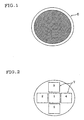
- Fig. 1 is a schematic view showing the region sampled for determining Porosity 1 (product-to-product difference) for ceramic honeycomb structural bodies according to each Examples and each Comparative Examples.
- Fig. 2 is a schematic view showing the region sampled for determining Porosity 2 (uniformity of reinforced partition wall part) for ceramic honeycomb structural bodies according to each Examples and each Comparative Examples.
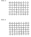
- Fig. 3 is an enlarged view showing a condition of a part of the partition walls in the ceramic honeycomb structure obtained by the production method of Example 1.
- Fig. 4 is an enlarged view showing a condition of a part of the partition walls in the ceramic honeycomb structure obtained by the production method of Comparative Example 2.
- Figs. 5 are explanatory views schematically showing an embodiment of the ceramic honeycomb structure of the present invention.
- Fig. 5(a) is a perspective view
- Fig 5(b) is a plane view
- Fig. 5(c) is a side view.
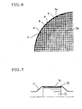
- Fig. 6 is a partially enlarged view schematically showing another embodiment of the present invention.
- Fig. 7 is an explanatory view schematically showing an example in which the ceramic honeycomb structure of the present invention is incorporated into a converter container.
- Fig. 8 is a view showing the condition of the engine revolutions in the erosion test.
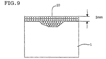
- Fig. 9 is an explanatory view schematically showing a method of determining an erosion amount.
- the ceramic honeycomb structure according to the present invention is a ceramic honeycomb structure comprising a cell group consisting of a plurality of cells which are divided each other by porous partition walls and functions as a fluid channel and a porous outer wall surrounding and holding outermost peripheral cells located at a circumference of the cell group, wherein in the partition walls, a part located at least one opening end of the cells of the cell group is a reinforced partition wall part having higher strength than the part other than the part located at least one opening end of the cells (hereinafter, referred to as "normal partition wall part") as well as having a variation of a porosity per unit volume (hereinafter, referred to as "maximum difference in porosity") within ⁇ 2%.
- FIGs. 5 are explanatory views schematically showing an embodiment of the ceramic honeycomb structure of the present invention.
- Fig. 5(a) is a perspective view
- Fig 5(b) is a plane view
- Fig. 5(c) is a side view.
- Fig. 6 is a partially enlarged view schematically showing another embodiment of the present invention.
- a ceramic honeycomb structure 1 has a cell group consisting of a plurality of cells 3 which are divided each other by a plurality of porous partition walls (cell partition walls 2) and functioning as a fluid channel and a porous outer wall 4 surrounding and holding outermost peripheral cells 8 located at a circumference of the cell group.
- the reference numeral 2a represents a peripheral cell partition wall
- the reference numeral 2b represents a basic cell partition wall
- the reference numeral 9 represents a second cell from the circumference of the cells.
- the ceramic honeycomb structure 1 according to the embodiment shown in Fig. 5 in the partition walls (cell partition walls 2), a part located at least one opening end 5 of the cells of the cell group constitutes a reinforced partition wall part having higher strength than the normal partition wall part. Therefore, the ceramic honeycomb structure 1 according to the present invention has excellent erosion resistance.
- the maximum difference in porosity of the reinforced partition wall part is within ⁇ 2%, in other words, high uniformity is achieved. Therefore, in the ceramic honeycomb structure 1 of the present embodiment, variation in chance of occurrence of erosion depending on the region of the reinforced partition wall part is very small, so that occurrence of local erosion phenomenon can be avoided. Accordingly, excellent erosion resistance is realized throughout the reinforced partition wall part.
- the maximum difference in porosity among five regions of the reinforced partition wall part is preferably within ⁇ 1.5%, more preferably within ⁇ 1% from the view point of giving more excellent erosion resistance.
- the phrase "maximum difference in porosity of the reinforced partition wall part" concretely means a variation of porosity per unit volume among any five regions within the reinforced partition wall part.
- the value of porosity (%) of the reinforced partition wall part is smaller than the value of porosity (%) of the normal partition wall part preferably by 3(%) or more, more preferably by 5(%) or more, and especially preferably by 8(%) or more. If the value of porosity (%) of the reinforced partition wall part is smaller than the value of porosity (%) of the normal partition wall part by less than 3(%), such case is unfavorable because sufficient erosion resistance is difficult to be exerted.
- the upper limit of the value by which the value of porosity (%) of the reinforced partition wall part is smaller than the value of porosity (%) of the normal partition wall part is not particularly restricted, but it should be generally 12(%) or less.
- the porosity of the reinforced partition wall part is preferably not more than 30%, more preferably in the range of 13% to 25%, still preferably in the range of 15% to 23%, and most preferably in the range of 18% to 21% from the view point of achieving both the thermal shock resistance and the erosion. resistance.
- the minimum wall thickness of the partition walls is preferably in the range of 0.030 mm to 0.076 mm, and more preferably in the range of 0.030 mm to 0.065 mm.
- the reinforced partition wall part is disposed in a part or the whole of the range within 30 mm, more preferably within 10 mm in the axial direction from at least one end face of the opening end of the cells.
- the reinforced partition wall parts may extend the same axial length from the end face of the opening end of the cells, however, it is preferred that the length from the end face of the opening end of the cells to the tip end of each reinforced partition wall part is not equal throughout the reinforced partition wall part, from the view point of achieving both the erosion resistance and small heat capacity, and restraining stress concentration at the boundary where the porosity changes.
- the wall thickness of the reinforced partition wall part is larger than the wall thickness of the normal partition wall part. More specifically, the wall thickness of the reinforced partition wall part is preferably 1.20 to 4.00 times the wall thickness of the normal partition wall part. Also it is preferred from the view point of avoiding stress concentration that the wall thickness of the reinforced partition wall part decreases sequentially or stepwise in the axial direction from at least one end face of the opening end of the cells to transit to the wall thickness of the normal partition wall part.
- Various kinds of reinforced partition wall parts may be used singly or in combination of two or more kinds.
- the cell walls 2a near the circumference of the honeycomb structure are made thick as shown in Fig. 6.
- isostatic strength is a strength obtained by a test conducted based on an automobile standard JASO M 505-87, and expressed by an applied pressure when breakage occurs.
- Tr1 The wall thickness of the outermost peripheral cells
- Tr2 The wall thickness of the second cell 9
- Tr5-15 Any cell (not shown) of fifth to fifteenth cells is indicated by Tr5-15.
- cell walls 2 are largely divided into cell walls 2a near the circumference and basic cell walls 2b.
- a relation between thickness (Tc) of partition walls forming the basic cells and each thickness (Tr1, Tr3-20) of partition walls forming the starting cell and the end cell is 1.10 ⁇ (Tr1, Tr3-20)/Tc ⁇ 3.00.
- this value [(Tr1, Tr3-20)/Tc] is less than 1.10, it does not contribute to improve erosion resistance and isostatic strength. Therefore it does not contribute to improve canning property.
- the value is more than 3.00, heat capacity and pressure loss are increased.
- each partition wall thickness (Tr1, Tr3-20) and the basic cell wall thickness (Tc) is more restricted so as to be 1.10 ⁇ (Tr1, Tr3-20)/Tc ⁇ 2.50, particularly 1.20 ⁇ (Tr1, Tr3-20)/Tc ⁇ 1.60.
- the ceramic honeycomb structure according to the present embodiment is made of at least one kind of ceramic selected from the group consisting of cordierite, alumina, mullite, silicon nitride, aluminum titanate, zirconia and silicon carbide, for example.
- the sectional shape of the ceramic honeycomb structure perpendicular to the channel in the present embodiment there can be mentioned, for example, a circle, an ellipse, an oval, a trapezoid, a triangle, a tetragon, a hexagon or an asymmetry. Of these, a circle, an ellipse or an oval is preferred.
- polygonal shapes having three or more vertexes such as square, rectangle or hexagon can be exemplified.
- a triangle, a tetragon or a hexagon is preferred.
- the honeycomb structure can be used in various applications such as various filters, a catalyst carrier and the like.
- the ceramic honeycomb structure is preferably used particularly for a carrier for purification of automobile exhaust gas.
- the ceramic honeycomb structure of the present embodiment is preferably used by being accommodated in a catalytic converter case as shown in Fig. 7.
- the ceramic honeycomb structure 13 is accommodated in a converter case 11 by being held with the ring 12 at the outer surface.
- a metallic mesh-made ring is used ordinarily.
- a holding member 14 such as mat, cloth or the like is interposed preferably.
- the method of producing the ceramic honeycomb structure of the present invention comprises the steps of obtaining a base material which is a unfired dry body of honeycomb structure having a plurality of partition walls using a kneaded compound based on a ceramic material, adhering a partition wall reinforcing agent to a part of partition wall located at least one of the opening ends of the cells in the base material, and firing the resultant base material, wherein as the partition wall reinforcing agent, a material based on a compound having at least one kind of atom selected from the group consisting of Si, Ti, Mg and Al in its structure is used.
- the base material normal partition wall part
- formation of the reinforced partition wall part since firing of the base material (normal partition wall part) and formation of the reinforced partition wall part can be simultaneously conducted, it is possible to improve the productivity and greatly reduce the product cost. Additionally, since the hydrophobic compound is used as the partition wall reinforcing agent, the water-soluble organic binder will not dissolve and swell when the partition wall reinforcing agent adheres to the partition walls, so that a ceramic honeycomb structure having desired performance can be obtained without causing deformation of the partition walls such as cell twisting.
- the partition wall reinforcing agent since a compound having in its structure an atom contributing to reinforcement of partition wall is used as the partition wall reinforcing agent, the atom contributing to reinforcement of partition wall is usually located in a uniform manner in its physiochemical property. For this reason, it is possible to form a uniform reinforced partition wall part without taking a special measure such as dispersing, and to almost completely avoid an occurrence of local erosion. Therefore, even when the mean porosity is uniform throughout the reinforced partition wall part, it is possible to form a reinforced partition wall part having better erosion resistance than the conventional ceramic honeycomb structure. Furthermore, by using the above partition wall reinforcing agent, a product-to-product variation of erosion resistance is also eliminated. Therefore, it is possible to obtain a ceramic honeycomb structure having excellent erosion resistance more stably by a easier process. In the following, concrete explanation will be made for each step.
- first a formed body of honeycomb structure having a plurality of partition walls is prepared using a kneaded compound based on a ceramic material.
- the ceramic material is not particularly limited, and at least one selected from the group consisting of silicon carbide, boron carbide, titanium carbide, zirconium carbide, silicon nitride, boron nitride, aluminum nitride, alumina, zirconia, mullite, cordierite forming raw material, aluminum titanate and sialon can be used.
- the relationship with the partition wall reinforcing agent will be described later.
- additives may be contained in the kneaded compound as necessary.
- examples of such additive include water-soluble organic binders, crystal growth auxiliary agents, dispersing agents and pore-forming agents.
- water-soluble organic binders include hydroxypropylmethyl cellulose, methyl cellulose, hydroxyethyl cellulose, carboxylmethyl cellulose, polyvinyl alcohol and polyvinyl acetal.
- crystal growth auxiliary agents include magnesia, silica, yttria and iron oxide
- examples of the dispersing agents include ethylene glycol, dextrin, fatty acid soap and poly alcohols.
- examples of the pore-forming agents include graphite, wheat flour, starch, phenol resin and polyethylene terephthalate.
- the present embodiment since the hydrophobic compound is used as the partition wall reinforcing agent as described above, the water-soluble organic binder will not dissolve and swell when the partition wall reinforcing agent is adhered to the partition wall, so that deformation of partition wall such as cell twisting will not occur. Therefore, the present embodiment is desirably applied to the production method in which the water-soluble organic binder is contained in the kneaded compound.
- the kneaded compound may be prepared in a routine method, for example, by mixing a predetermined amount of water or the like into the ceramic material into which an additive such as water-soluble organic binder has been added, adding another additive as necessary, and kneading the resultant mixture using a kneader, pressure kneader or vacuum auger machine.
- the method for obtaining a formed body of honeycomb structure is not particularly restricted.
- extrusion forming is preferred, and for example, extrusion forming using an extruder such as ram extruder or twin-screw extruder is preferred.
- the thickness of partition wall of the base material is not particularly restricted.
- a formed body having a desired honeycomb structure is obtained without causing deformation in the partition walls.
- the obtained formed body is dried to obtain a base material which is a dry body having a honeycomb structure.
- any suitable drying methods can be employed insofar as they will not substantially cause firing. Examples of the drying methods include the blast drying, hot air drying and microwave drying.
- drying body means an unfired dry body which is not substantially fired.
- the partition wall reinforcing agent is adhered to the plurality of partition walls located at the opening ends of the cells of the resultant base material (dry body).
- those based on the compounds having at least one atom in their structures more specifically at least one atom selected from the group consisting of Si, Ti, Mg and Al that makes the partition walls located at the ends more close-grained by lowering the melting point of the base material forming material, or going into the fine pores in the partition walls to lower the volume of the fine pores are used as the partition wall reinforcing agent.
- the compound that is to be a basis of the partition wall reinforcing agent compounds that generate inorganic oxides upon firing are preferred.
- aluminate alkoxy oligomers such as acetoalkoxy aluminum diisopropylate or titanate alkoxy oligomers used as a coupling agent are preferably used.
- compounds having a siloxane bond for example, silicone oil, silicon varnish, silicate alkoxy oligomer, mixtures thereof and the like are preferred.
- silicone oil examples include dimethyl silicone oil, methylphenyl silicone oil, methyl hydrogen silicone oil, amino-modified silicone oil, epoxy-modified silicone oil, carboxyl-modified silicone oil, carbinol-modified silicone oil, methacryl-modified silicone oil, mercapto-modified silicone oil, phenol-modified silicone oil, one end reactive silicone oil, different functional group-modified silicone oil, polyether silicone oil, methylstylyl-modified silicone oil, alkyl-modified silicone oil or higher fatty acid ester-modified.
- the partition wall reinforcing agent may be prepared from one compound or mixture of two or more kinds selected from the compounds as exemplified above. It is especially preferred to prepare the partition wall reinforcing agent by mixing two or more kinds.
- the partition wall reinforcing agent is prepared by mixing two or more kinds of the aforementioned compounds, it is possible to select and mix the above compounds having a variety of viscosities, and hence to adjust the viscosity of the partition wall reinforcing agent as desired. This facilitates uniform adhesion of the partition wall reinforcing agent.
- partition wall reinforcing agent prepared by mixing silicate alkoxy oligomer or methyl hydrogen silicon oil into dimethyl silicone oil, for example.
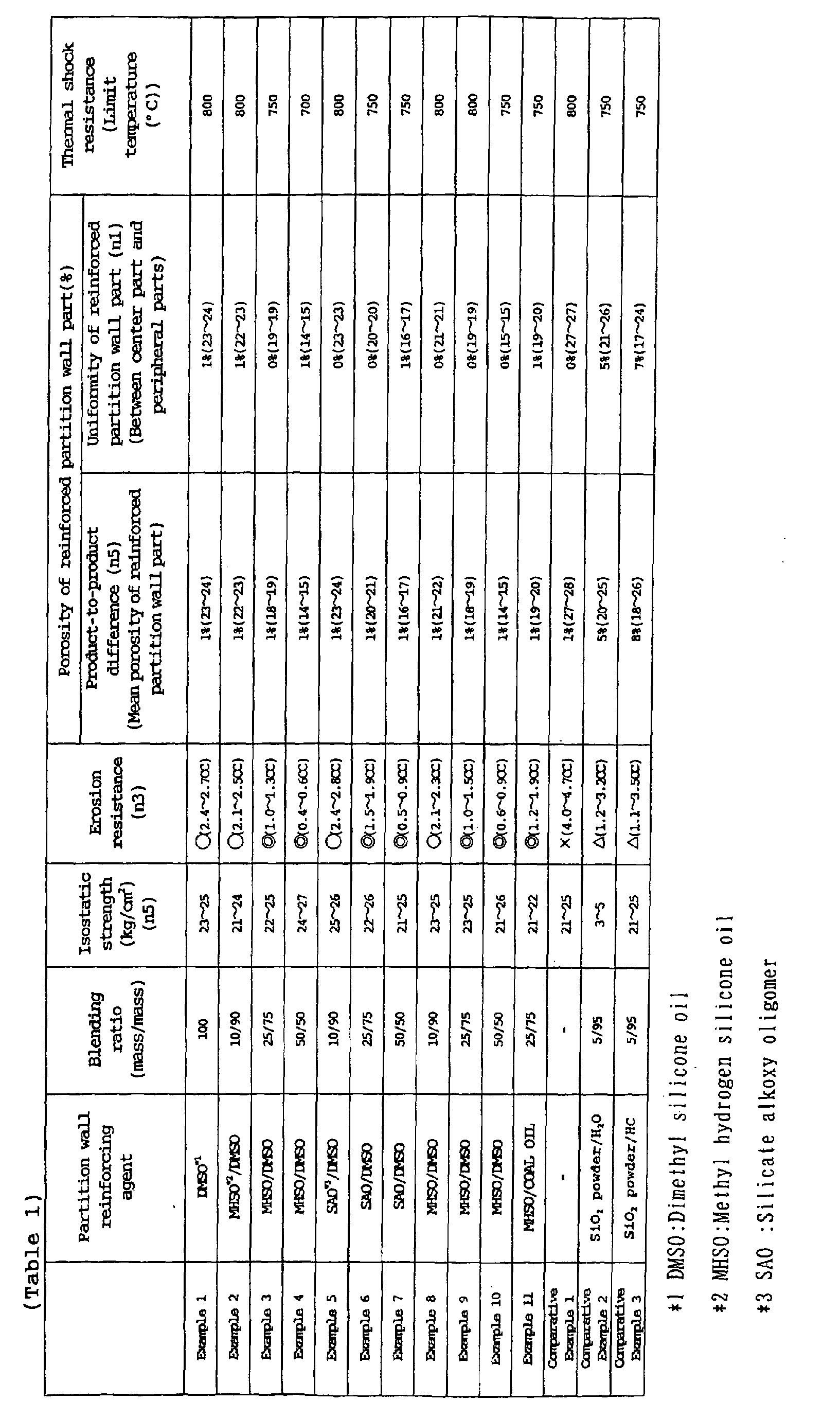
- the blending ratio of silicate alkoxy oligomer (SAO) or methyl hydrogen silicone oil (MHSO) to dimethyl silicone oil (DMSO) is preferably from 10/90 to 75/25 (mass/mass), more preferably from 15/85 to 50/50 (mass/mass), and more preferably from 20/80 to 50/50 (mass/mass), especially preferably from 25/75 to 50/50 (mass/mass).
- SAO silicate alkoxy oligomer
- MHSO methyl hydrogen silicone oil
- DMSO dimethyl silicone oil
- the blending ratio falls within these ranges, it is possible to obtain a ceramic honeycomb structure having excellent erosion resistance while ensuring desired thermal shock resistance.
- the partition wall reinforcing agent in the present embodiment may be the aforementioned compounds such as silicone oil, that are diluted in a diluent containing one or more than one selected from aromatic hydrocarbons such as toluene or xylene, aliphatic hydrocarbons such as petroleum ether or kerosene, petroleum-based hydrocarbons such as coal oil or diesel oil, alcohols such as isopropyl alcohol, lauryl alcohol or butanol, volatile silicone oils and so on.
- the partition wall reinforcing agent has an absolute viscosity of preferably from 1 to 10000 mPa ⁇ s, and more preferably from 10 to 1000 mPa ⁇ s.
- a compound having low viscosity is small in degree of polymerization and tends to volatilize easily. If the viscosity is less than 1 mPa ⁇ s, when the compound adhered to the partition walls is fired, Si or the like active ingredient existing in the partition wall reinforcing agent volatilizes together with CO 2 and H 2 O, so that it becomes difficult to form a rigid reinforced partition wall part. To the contrary, if the viscosity is more than 10000 mPa ⁇ s, the partition wall reinforcing agent is difficult to be adhered to the partition walls at uniform thickness.
- the partition wall reinforcing agent in the present embodiment is suitably selected for each kind of ceramic material.
- the partition wall reinforcing agent in the present embodiment is suitably selected for each kind of ceramic material.
- compounds having Si in their structures such as silicon oil are preferably selected.
- the partition wall reinforcing agent when adhered to the partition walls, by dipping the base material in the partition wall reinforcing agent from the end face of the opening end of the cells to a predetermine height, it is possible to readily and uniformly adhere the partition wall reinforcing agent to all the partition walls.
- This procedure is ideal in that the region where the reinforced partition wall part is to be provided can be easily and arbitrarily controlled.
- Spray application can also be used for achieving uniform application of the partition wall reinforcing agent, however, with the spray application, it is difficult to arbitrarily control the region where the reinforced partition wall part is to be provided.
- the base material to which the partition wall reinforcing agent has adhered is subjected to at least one firing to simultaneously conduct firing (formation) of the normal partition wall part and firing (formation) of the reinforced partition wall part.
- the base material and the partition wall reinforcing agent in advance of the firing step, and examples of the drying method include blast drying, hot air drying and microwave drying.
- the firing condition it is preferred to arbitrarily select a desired condition depending on the kinds of the base material and the partition wall reinforcing agent.
- the firing may be conducted at 1300 to 1500°C.
- the production method according to the present embodiment was explained step by step.
- the production method of the present embodiment it is possible to produce a ceramic honeycomb structure having excellent erosion resistance stably by a single firing step without causing deformation or the like in the partition walls, while achieving high productivity and great reduction of the product cost.
- a ceramic material comprising a cordierite forming raw material
- 8 parts by mass of methylcellulose, 0.5 part by mass of potassium laurate soap, 2 parts by mass of polyether and 28 parts by mass of water were mixed, and the resultant mixture was loaded to a continuous extruder to obtain a formed body having a honeycomb structure.
- This formed body was dried to obtain a base material (unfired dry body) having a honeycomb structure.
- the obtained base material was dipped in a partition wall reinforcing agent comprising dimethyl silicone oil (manufactured by Shin-Etsu Chemical Co., Ltd. under the trade name of KF96-100CS, absolute viscosity: about 100 mPa ⁇ s) at a depth of 5 mm in the axial direction from the opening end of the cells, to allow partition wall reinforcing agent to adhere the partition walls located at the opening end of the cells of the base material. Immediately after that, compressed air at room temperature was fed to remove the partition wall reinforcing agent that was adhered in excess.
- a partition wall reinforcing agent comprising dimethyl silicone oil (manufactured by Shin-Etsu Chemical Co., Ltd. under the trade name of KF96-100CS, absolute viscosity: about 100 mPa ⁇ s) at a depth of 5 mm in the axial direction from the opening end of the cells, to allow partition wall reinforcing agent to adhere the partition walls located at the opening end of the cells of
- the base material having a honeycomb structure bearing the partition wall reinforcing agent adhered to the partition walls located at the opening end of the cells was fired at 1400°C for four hours to produce a cylindrical ceramic honeycomb structure (not bearing catalyst) having a partition wall thickness of 0.064 mm, diameter of 100 mm and height of 100 mm with square cells in the density of 140 cells/cm 2 , and having a porosity of 85.5%.
- the porosity of the normal partition wall part of the produced ceramic honeycomb structure was from 27 to 28%.
- a ceramic honeycomb structure was prepared in the same manner as described in Example 1 except that as the partition wall reinforcing agent, methyl hydrogen silicone oil (manufactured by Shin-Etsu Chemical Co., Ltd. under the trade name of KF99, absolute viscosity: about 20 mPa ⁇ s) and dimethyl silicone oil (manufactured by Shin-Etsu Chemical Co., Ltd. under the trade name of KF96L-0.65CS, absolute viscosity: about 0.65 mPa ⁇ s) blended in the ratios (mass/mass) of 10/90, 25/75 and 50/50 were respectively used.
- methyl hydrogen silicone oil manufactured by Shin-Etsu Chemical Co., Ltd. under the trade name of KF99, absolute viscosity: about 20 mPa ⁇ s
- dimethyl silicone oil manufactured by Shin-Etsu Chemical Co., Ltd. under the trade name of KF96L-0.65CS, absolute viscosity: about 0.65 mPa ⁇ s
- a ceramic honeycomb structure was prepared in the same manner as described in Example 1 except that as the partition wall reinforcing agent, silicate alkoxy oligomer (manufactured by Shin-Etsu Chemical Co., Ltd. under the trade name of KR-500, absolute viscosity: about 20 mPa ⁇ s) and dimethyl silicone oil (manufactured by Shin-Etsu Chemical Co., Ltd. under the trade name of KF96L-0.65CS, absolute viscosity: about 0.65 mPa ⁇ s) blended in the ratios (mass/mass) of 10/90, 25/75 and 50/50 were respectively used.
- silicate alkoxy oligomer manufactured by Shin-Etsu Chemical Co., Ltd. under the trade name of KR-500, absolute viscosity: about 20 mPa ⁇ s
- dimethyl silicone oil manufactured by Shin-Etsu Chemical Co., Ltd. under the trade name of KF96L-0.65CS, absolute viscosity: about 0.
- a ceramic honeycomb structure was prepared in the same manner as described in Example 1 except that as the partition wall reinforcing agent, methyl hydrogen silicone oil (manufactured by Shin-Etsu Chemical Co., Ltd. under the trade name of KF99, absolute viscosity: about 20 mPa ⁇ s) and dimethyl silicone oil (manufactured by Shin-Etsu Chemical Co., Ltd. under the trade name of KF96L-1000CS, absolute viscosity: about 1000 mPa ⁇ s) blended in the ratios (mass/mass) of 10/90, 25/75 and 50/50 were respectively used.
- methyl hydrogen silicone oil manufactured by Shin-Etsu Chemical Co., Ltd. under the trade name of KF99, absolute viscosity: about 20 mPa ⁇ s
- dimethyl silicone oil manufactured by Shin-Etsu Chemical Co., Ltd. under the trade name of KF96L-1000CS, absolute viscosity: about 1000 mPa ⁇ s
- a ceramic honeycomb structure was prepared in the same manner as described in Example 1 except that as the partition wall reinforcing agent, methyl hydrogen silicone oil (manufactured by Shin-Etsu Chemical Co., Ltd. under the trade name of KF99, absolute viscosity: about 20 mPa ⁇ s) and coal oil (manufactured by Nisseki Mitsubishi Co., Ltd.) blended in the ratio (mass ratio) of 25/75 were used.
- methyl hydrogen silicone oil manufactured by Shin-Etsu Chemical Co., Ltd. under the trade name of KF99, absolute viscosity: about 20 mPa ⁇ s
- coal oil manufactured by Nisseki Mitsubishi Co., Ltd.
- a honeycomb structure was prepared in the same manner as described in Example 1 except that a partition wall reinforcing agent is not adhered to the base material having a honeycomb structure.
- a ceramic honeycomb structure was prepared in the same manner as described in Example 1 except that as the partition wall reinforcing agent was used a dispersion prepared by adding 0.5 parts by mass of dispersing agent (alkyl acetalized polyvinyl alcohol, manufactured by SEKISUI CHEMICAL CO., LTD. under the trade name of S-LEC KW-3) to 100 parts by mass of a dispersion of 5% by mass of silica (SiO 2 ) powder in water serving as a dispersing medium.
- dispersing agent alkyl acetalized polyvinyl alcohol, manufactured by SEKISUI CHEMICAL CO., LTD. under the trade name of S-LEC KW-3
- a ceramic honeycomb structure was prepared in the same manner as described in Example 1 except that as the partition wall reinforcing agent was used a dispersion prepared by adding 0.5 parts by mass of dispersing agent (polyoxyalkylene group polymer, manufactured by NOF CORPORATION under the trade name of MALIALIM AKM-0531) to 100 parts by mass of a dispersion of 5% by mass of silica (SiO 2 ) powder in petroleum-based hydrocarbon (manufactured by Nisseki Mitsubishi Co., Ltd., coal oil/CRISEF oil (trade name) F8 mixture, main component: coal oil) serving as a dispersing medium.
- dispersing agent polyoxyalkylene group polymer, manufactured by NOF CORPORATION under the trade name of MALIALIM AKM-0531
- silica (SiO 2 ) powder in petroleum-based hydrocarbon (manufactured by Nisseki Mitsubishi Co., Ltd., coal oil/CRISEF oil (trade name) F8 mixture, main component: coal
- the ceramic honeycomb structure obtained in each of Examples and Comparative Examples was examined for porosity, erosion resistance, isostatic strength and thermal shock resistance in the manner as described below.
- a measuring sample 6 was cut out in an area of 70 cm 2 which is almost the whole area of the end face in the reinforced partition wall part, and porosity of each measuring sample was measured, and the maximum difference was determined in the manner as described below.
- measuring samples 7 having an area of 9 cm 2 were cut out at the total of five regions including one center region and four peripheral regions in the end face, and porosity of each measuring sample was measured, and the maximum difference was determined in the manner as described below.
- a metallic can holding and accommodating a ceramic honeycomb structure was connected to the exhaust port of a gasoline engine of in-line four cylinders and 1.8 liters displacement. That is, a sample was placed right near the engine.
- the engine was operated under the conditions shown in Fig. 8 and, when the engine revolutions reached 6,000 rpm, 0.1 g of abrasive grains (silicon carbide, GC 320, average particle diameter: 50 im) were added. Further, the engine operation was continued under the conditions shown in Fig. 8; once in each two cycles (one cycle: 130 seconds), abrasive grains were added; this was repeated continuously.
- Test was conducted several times by changing the total amount of abrasive grains added between about 2 g and 16 g, and from the results was calculated the erosion amount (wind erosion volume) of the ceramic honeycomb structure when the amount of abrasive grains added was 10 g.
- Erosion amount was measured by, as shown in Fig. 9, winding a rubber sheet round the end face of a ceramic honeycomb structure 1 whose erosion amount was to be measured, placing therein ceramic-made beads of 1.5 mm in diameter at a height of about 3 mm, then recovering them to measure the volume of beads, and calculating a difference between beads volume after erosion test and beads volume before the test. This was conducted three times and an average thereof was taken as erosion amount. Evaluation was made on three ceramic honeycomb structural bodies obtained in each of Examples and Comparative Examples. When the erosion amount exceeds 3 cc in all the three samples, the symbol " ⁇ " was given representing unendurability to practical use.
- a test based on an automobile standard JASO M 505-87 was conducted to measure a value of applied pressure when breakage occurs.
- the value represents isostatic strength (kg/cm 2 ).
- the ceramic honeycomb structure After heating the ceramic honeycomb structure to a predetermined temperature in an electric furnace, the ceramic honeycomb structure was taken out and placed in room temperature atmosphere of 20°C, and whether defects such as cracking occurred due to thermal shock were visually checked both in the elevated temperature condition immediately after taking out the ceramic honeycomb structure, and in the condition after cooling by cold air (the condition at 20°C). When no defect was observed, the heating temperature was further elevated, and the test was repeated until some defect occurred. The temperature at which the defect occurred was determined to evaluate the thermal shock resistance.
- the maximum difference in porosity was as large as 5%, so that a local erosion phenomenon is more likely to occur compared to the ceramic honeycomb structure obtained in Example as will be described later. This suggests that when the mean porosity is uniform throughout the reinforced partition wall part, the erosion resistance is smaller.
- Fig. 3 shows a ceramic honeycomb structure obtained in Example 1
- the entire reinforced partition wall part had a mean porosity in the range of 14 to 24%, which is lower by 3 to 13% than that of the unreinforced part, suggesting that erosion resistance is increased.
- the maximum difference in mean porosity of the entire reinforced partition wall part among the five ceramic honeycomb structural bodies was 1%, representing very small variation, and that the erosion resistance was not more than 3 cc in every case.
- the reinforced partition wall part was uniformly formed as is apparent from the maximum difference in porosity of not more than 1%. This suggests that a local erosion phenomenon is not likely to occur in the reinforced partition wall part, and the erosion resistance is improved in the entire reinforced partition wall part.
- the present invention it is possible to obtain a honeycomb structure having desired performance without causing any deformation or the like in partition walls while dramatically improving the productivity and achieving cost reduction. Additionally, it is possible to accurately form a sophisticated and uniform reinforced partition wall part, and to stably obtain a ceramic honeycomb structure having excellent erosion resistance. Of course, the obtained ceramic honeycomb structure has greatly uniformed porosity throughout the reinforced partition wall part, and hence has more excellent erosion resistance because local erosion phenomenon is avoided almost completely.
Landscapes
- Chemical & Material Sciences (AREA)
- Engineering & Computer Science (AREA)
- Ceramic Engineering (AREA)
- Chemical Kinetics & Catalysis (AREA)
- Materials Engineering (AREA)
- Organic Chemistry (AREA)
- Manufacturing & Machinery (AREA)
- Structural Engineering (AREA)
- Inorganic Chemistry (AREA)
- Health & Medical Sciences (AREA)
- Environmental & Geological Engineering (AREA)
- Geometry (AREA)
- Physics & Mathematics (AREA)
- Mechanical Engineering (AREA)
- General Chemical & Material Sciences (AREA)
- General Engineering & Computer Science (AREA)
- Oil, Petroleum & Natural Gas (AREA)
- Combustion & Propulsion (AREA)
- Toxicology (AREA)
- Biomedical Technology (AREA)
- Analytical Chemistry (AREA)
- Geology (AREA)
- Life Sciences & Earth Sciences (AREA)
- Catalysts (AREA)
- Filtering Materials (AREA)
- Devices For Post-Treatments, Processing, Supply, Discharge, And Other Processes (AREA)
- Exhaust Gas After Treatment (AREA)
- Exhaust Gas Treatment By Means Of Catalyst (AREA)
- Porous Artificial Stone Or Porous Ceramic Products (AREA)
Abstract
Description
Claims (20)
- A ceramic honeycomb structure comprising:characterized in that in the partition walls, a part located at least one opening end of the cells of the cell group constitutes a reinforced partition wall part having higher strength than the other part of the partition walls (normal partition wall part) as well as having a variation of porosity per unit volume within ± 2%.a cell group having cells, the cells being divided each other by porous partition walls and functioning as a fluid channel; anda porous outer wall surrounding and holding outermost peripheral cells located at a circumference of the cell group,
- The ceramic honeycomb structure according to claim 1, wherein the value of porosity (%) of the reinforced partition wall part is smaller than the value of porosity (%) of the normal partition wall part by 3(%) or more.
- The ceramic honeycomb structure according to claim 1 or 2, wherein porosity of the reinforced partition wall is 30% or less.
- The ceramic honeycomb structure according to any one of claims 1 to 3, wherein the minimum partition wall thickness of the partition walls is in the range of 0.030 to 0.076 mm.
- The ceramic honeycomb structure according to any one of claims 1 to 4, wherein the length of the reinforced partition wall part from the end face of the opening end of the cells to a tip end thereof is not uniform throughout the reinforced partition wall part.
- The ceramic honeycomb structure according to any one of claims 1 to 5, wherein the partition wall thickness of the reinforced partition wall part is larger than the partition wall thickness of the normal partition wall part.
- The ceramic honeycomb structure according to any of claims 1 to 6, wherein taking the outermost peripheral cell as a starting cell, taking any cell of the third to the twentieth cell located inwardly from the starting cell as an end cell and taking cells located inwardly from the end cell as basic cells, a relation between thickness (Tc) of partition walls forming the basic cells and each thickness (Tr1, Tr3-20) of partition walls forming the starting cell and the end cell is 1.10 ≦ (Tr1, Tr3-20)/Tc ≦ 3.00.
- The ceramic honeycomb structure according to any one of claims 1 to 7, comprising at least one kind of ceramic selected from the group consisting of cordierite, alumina, mullite, silicon nitride, aluminum titanate, zirconia and silicon carbide.
- The ceramic honeycomb structure according to any of claims 1 to 8, wherein a sectional shape of the honeycomb structure perpendicular to the channel is circular, elliptic, oval, trapezoidal, triangular, tetragonal, hexagonal or asymmetric.
- The ceramic honeycomb structure according to any of claims 1 to 9, wherein the sectional shape of the honeycomb structure perpendicular to the channel is triangular, tetragonal or hexagonal.
- The ceramic honeycomb structure according to any one of claims 1 to 10 used as a carrier of catalyst for automobile exhaust gas emission control.
- The ceramic honeycomb structure according to any one of claims 1 to 11, incorporated into a catalyst converter in such a manner that the partition walls bear a catalyst component and the ceramic honeycomb structure is held at the outer circumference of the outer wall.
- A method of producing a ceramic honeycomb structure comprising the steps of:characterized in that as the partition wall reinforcing agent, the one that is based on a compound having in its structure at least one atom selected from the group consisting of Si, Ti, Mg and Al is used.obtaining a base material which is a dry body having a honeycomb structure with a plurality of partition walls by using a kneaded compound based on a ceramic material;adhering a partition wall reinforcing agent to a part located at at least one of the opening ends of the cells of the base material; andfiring the base material;
- The method of producing a ceramic honeycomb structure according to claim 13, wherein the basis of the partition wall reinforcing agent is a compound that generates an inorganic oxide upon firing.
- The method of producing a ceramic honeycomb structure according to claim 13 or 14, wherein the basis of the partition wall reinforcing agent is a compound that has a siloxane bond.
- The method of producing a ceramic honeycomb structure according to any one of claims 13 to 15, wherein the basis of the partition wall reinforcing agent is silicone oil, silicone varnish, alkoxy oligomer or mixture thereof.
- The method of producing a ceramic honeycomb structure according to any one of claims 13 to 16, wherein absolute viscosity of the partition wall reinforcing agent is in the range of 1 to 10000 mPa·s.
- The method of producing a ceramic honeycomb structure according to any one of claims 13 to 17, wherein the ceramic material is a cordierite forming raw material.
- The method of producing a ceramic honeycomb structure according to any one of claims 13 to 18, wherein the kneaded compound contains a water-soluble organic binder.
- The method of producing a ceramic honeycomb structure according to claim 19, wherein the water-soluble organic binder comprises at least one kind of water-soluble compound selected from the group consisting of hydroxypropylmethyl cellulose, methylcellulose, hydroxyethyl cellulose, carboxylmethyl cellulose, polyvinyl alcohol and polyvinyl acetal.
Applications Claiming Priority (5)
| Application Number | Priority Date | Filing Date | Title |
|---|---|---|---|
| JP2002072488 | 2002-03-15 | ||
| JP2002072488 | 2002-03-15 | ||
| JP2003002960 | 2003-01-09 | ||
| JP2003002960A JP4294964B2 (en) | 2002-03-15 | 2003-01-09 | Manufacturing method of ceramic honeycomb structure |
| PCT/JP2003/002055 WO2003078121A1 (en) | 2002-03-15 | 2003-02-25 | Ceramic honeycomb structural body and method of manufacturing the structural body |
Publications (3)
| Publication Number | Publication Date |
|---|---|
| EP1486305A1 true EP1486305A1 (en) | 2004-12-15 |
| EP1486305A4 EP1486305A4 (en) | 2007-08-29 |
| EP1486305B1 EP1486305B1 (en) | 2014-07-02 |
Family
ID=28043729
Family Applications (1)
| Application Number | Title | Priority Date | Filing Date |
|---|---|---|---|
| EP03707052.1A Expired - Lifetime EP1486305B1 (en) | 2002-03-15 | 2003-02-25 | Fired ceramic honeycomb structural body |
Country Status (9)
| Country | Link |
|---|---|
| US (1) | US7413717B2 (en) |
| EP (1) | EP1486305B1 (en) |
| JP (1) | JP4294964B2 (en) |
| KR (1) | KR100607480B1 (en) |
| CN (1) | CN100482429C (en) |
| AU (1) | AU2003211675A1 (en) |
| BR (1) | BR0308468A (en) |
| CA (1) | CA2477837A1 (en) |
| WO (1) | WO2003078121A1 (en) |
Cited By (2)
| Publication number | Priority date | Publication date | Assignee | Title |
|---|---|---|---|---|
| EP1547743A4 (en) * | 2002-08-21 | 2006-05-17 | Ngk Insulators Ltd | METHOD FOR MANUFACTURING A HONEYCOMB STRUCTURE |
| FR2931697A1 (en) * | 2008-05-29 | 2009-12-04 | Saint Gobain Ct Recherches | CATALYTIC FILTER OR SUPPORT BASED ON SILICON CARBIDE AND ALUMINUM TITANATE |
Families Citing this family (25)
| Publication number | Priority date | Publication date | Assignee | Title |
|---|---|---|---|---|
| WO2007049338A1 (en) * | 2005-10-25 | 2007-05-03 | Ngk Insulators, Ltd. | Honeycomb filter |
| US20090010817A1 (en) * | 2004-10-12 | 2009-01-08 | Ngk Insulators, Ltd. | Honeycomb filter |
| CN100386150C (en) * | 2005-08-17 | 2008-05-07 | 云南菲尔特环保科技有限公司 | Ceramic catalyst carrier, particle trap and particle trapping device and preparation method thereof |
| KR100667028B1 (en) * | 2005-10-04 | 2007-01-10 | 희성엥겔하드주식회사 | Reductionless injection SCR catalytic converter |
| JP4788497B2 (en) * | 2005-12-27 | 2011-10-05 | 株式会社デンソー | Hex honeycomb structure |
| JP5223340B2 (en) * | 2006-01-27 | 2013-06-26 | 日立金属株式会社 | Manufacturing method of ceramic honeycomb filter |
| US7674513B2 (en) * | 2006-03-31 | 2010-03-09 | Corning Incorporated | Crack-resistant ceramic honeycomb structures |
| JP2010227818A (en) * | 2009-03-26 | 2010-10-14 | Ngk Insulators Ltd | Honeycomb structure and honeycomb catalyst |
| US20100304041A1 (en) * | 2009-05-29 | 2010-12-02 | Tonia Havewala Fletcher | Method For Coating Honeycomb Bodies |
| JP2011162430A (en) * | 2010-01-14 | 2011-08-25 | Shin-Etsu Chemical Co Ltd | Water-soluble binder for ceramic molding and ceramic molding composition using the same |
| JP5757297B2 (en) * | 2013-01-23 | 2015-07-29 | トヨタ自動車株式会社 | Catalytic converter |
| JP6540260B2 (en) * | 2015-06-18 | 2019-07-10 | 株式会社デンソー | Honeycomb structure and automotive catalytic converter |
| JP6587565B2 (en) * | 2016-03-17 | 2019-10-09 | 日本碍子株式会社 | Honeycomb structure |
| JP6788515B2 (en) * | 2017-02-02 | 2020-11-25 | 日本碍子株式会社 | Sealed honeycomb structure |
| WO2019108918A1 (en) * | 2017-11-30 | 2019-06-06 | Corning Incorporated | Ceramic articles with bleed-through barrier and methods of manufacture thereof |
| JP7114886B2 (en) * | 2017-12-07 | 2022-08-09 | 株式会社デンソー | honeycomb structure |
| EP3727773B1 (en) | 2017-12-22 | 2022-07-13 | Corning Incorporated | Extrusion die |
| JP6881337B2 (en) * | 2018-01-30 | 2021-06-02 | 株式会社デンソー | Honeycomb structure and mold |
| CN112203741A (en) | 2018-05-31 | 2021-01-08 | 康宁股份有限公司 | Honeycomb body with a multi-region honeycomb structure and coextrusion production method |
| US11932582B2 (en) * | 2018-06-29 | 2024-03-19 | Corning Incorporated | Honeycomb bodies with controlled porosity gradient and firing methods thereof |
| WO2020005663A1 (en) | 2018-06-29 | 2020-01-02 | Corning Incorporated | Ceramic honeycomb bodies having high-strength skin and manufacturing methods thereof |
| JP7119970B2 (en) * | 2018-12-12 | 2022-08-17 | トヨタ自動車株式会社 | POSITION DETECTION METHOD AND POSITION DETECTION DEVICE |
| JP7004043B1 (en) * | 2020-08-21 | 2022-02-10 | 株式会社明電舎 | Ceramic flat membrane |
| JP7760319B2 (en) * | 2021-03-02 | 2025-10-27 | 日本碍子株式会社 | Method for manufacturing conductive honeycomb structure and method for manufacturing electrically heated carrier |
| CN116440852A (en) * | 2023-04-24 | 2023-07-18 | 北京工业大学 | PDMS-loaded integral round hole filler, preparation method and application |
Family Cites Families (21)
| Publication number | Priority date | Publication date | Assignee | Title |
|---|---|---|---|---|
| JPS54150406A (en) * | 1978-05-18 | 1979-11-26 | Nippon Soken | Ceramic honeycomb structure |
| JPS5599344A (en) | 1979-01-26 | 1980-07-29 | Mitsubishi Petrochem Co Ltd | End part reinforced abrasion-resistant catalyst molding for denitration |
| US4255316A (en) | 1979-04-26 | 1981-03-10 | Dow Corning Corporation | Ceramifiable silicone adhesives |
| JPS56129043A (en) * | 1980-03-14 | 1981-10-08 | Ngk Insulators Ltd | Honeycomb structure of ceramic |
| US4416675A (en) * | 1982-02-22 | 1983-11-22 | Corning Glass Works | High capacity solid particulate filter apparatus |
| US4902216A (en) * | 1987-09-08 | 1990-02-20 | Corning Incorporated | Extrusion die for protrusion and/or high cell density ceramic honeycomb structures |
| JP2608641B2 (en) | 1991-03-20 | 1997-05-07 | 日本碍子株式会社 | Honeycomb catalyst for purifying exhaust gas and method for producing the same |
| US6040266A (en) * | 1994-02-22 | 2000-03-21 | Ultramet | Foam catalyst support for exhaust purification |
| JPH08224720A (en) | 1995-02-22 | 1996-09-03 | Nippon Soken Inc | Method for manufacturing fiber-reinforced honeycomb structure |
| EP0745416B1 (en) * | 1995-06-02 | 2003-09-17 | Corning Incorporated | Device for removal of contaminants from fluid streams |
| US5952079A (en) * | 1996-08-07 | 1999-09-14 | Denso Corporation | Ceramic honeycomb structure and method of production thereof |
| US6217832B1 (en) * | 1998-04-30 | 2001-04-17 | Catalytica, Inc. | Support structures for a catalyst |
| JP3867439B2 (en) | 1998-06-03 | 2007-01-10 | 株式会社デンソー | Honeycomb structure and manufacturing method thereof |
| JP3394449B2 (en) * | 1998-06-18 | 2003-04-07 | 日本碍子株式会社 | Thin-walled honeycomb structure and method of reinforcing the same |
| JP3803850B2 (en) | 1999-02-25 | 2006-08-02 | 日立造船株式会社 | Curing treatment method for catalyst gas inflow end |
| US6381362B1 (en) * | 1999-04-08 | 2002-04-30 | Tata America International Corporation | Method and apparatus for including virtual ads in video presentations |
| JP4259703B2 (en) * | 1999-12-07 | 2009-04-30 | 株式会社デンソー | Ceramic honeycomb structure and manufacturing method thereof |
| JP2001226173A (en) | 1999-12-07 | 2001-08-21 | Denso Corp | Method for manufacturing honeycomb structure |
| DE19962544A1 (en) * | 1999-12-23 | 2001-07-19 | Degussa | Process for coating a ceramic honeycomb body |
| JP2001220245A (en) | 2000-02-07 | 2001-08-14 | Kousha:Kk | Extrusion molding method of ceramic material |
| JP2002070545A (en) * | 2000-08-25 | 2002-03-08 | Ibiden Co Ltd | Housing structure of ceramic honeycomb structure |
-
2003
- 2003-01-09 JP JP2003002960A patent/JP4294964B2/en not_active Expired - Fee Related
- 2003-02-25 EP EP03707052.1A patent/EP1486305B1/en not_active Expired - Lifetime
- 2003-02-25 KR KR1020047014509A patent/KR100607480B1/en not_active Expired - Fee Related
- 2003-02-25 US US10/506,184 patent/US7413717B2/en not_active Expired - Lifetime
- 2003-02-25 BR BR0308468-0A patent/BR0308468A/en not_active IP Right Cessation
- 2003-02-25 CA CA002477837A patent/CA2477837A1/en not_active Abandoned
- 2003-02-25 AU AU2003211675A patent/AU2003211675A1/en not_active Abandoned
- 2003-02-25 WO PCT/JP2003/002055 patent/WO2003078121A1/en not_active Ceased
- 2003-02-25 CN CNB038108925A patent/CN100482429C/en not_active Expired - Fee Related
Cited By (4)
| Publication number | Priority date | Publication date | Assignee | Title |
|---|---|---|---|---|
| EP1547743A4 (en) * | 2002-08-21 | 2006-05-17 | Ngk Insulators Ltd | METHOD FOR MANUFACTURING A HONEYCOMB STRUCTURE |
| US7501158B2 (en) | 2002-08-21 | 2009-03-10 | Ngk Insulators, Ltd. | Method for manufacturing honeycomb structure |
| FR2931697A1 (en) * | 2008-05-29 | 2009-12-04 | Saint Gobain Ct Recherches | CATALYTIC FILTER OR SUPPORT BASED ON SILICON CARBIDE AND ALUMINUM TITANATE |
| WO2009156638A1 (en) * | 2008-05-29 | 2009-12-30 | Saint-Gobain Centre De Recherches Et D'etudes Europeen | Catalytic filter or substrate containing silicon carbide and aluminum titanate |
Also Published As
| Publication number | Publication date |
|---|---|
| JP2003334455A (en) | 2003-11-25 |
| KR20050007441A (en) | 2005-01-18 |
| JP4294964B2 (en) | 2009-07-15 |
| EP1486305A4 (en) | 2007-08-29 |
| KR100607480B1 (en) | 2006-08-02 |
| CA2477837A1 (en) | 2003-09-25 |
| WO2003078121A1 (en) | 2003-09-25 |
| BR0308468A (en) | 2005-05-03 |
| AU2003211675A1 (en) | 2003-09-29 |
| CN1652907A (en) | 2005-08-10 |
| EP1486305B1 (en) | 2014-07-02 |
| US20050106083A1 (en) | 2005-05-19 |
| US7413717B2 (en) | 2008-08-19 |
| CN100482429C (en) | 2009-04-29 |
Similar Documents
| Publication | Publication Date | Title |
|---|---|---|
| US7413717B2 (en) | Ceramic honeycomb structural body and method of manufacturing the structural body | |
| EP1384508B1 (en) | Porous honeycomb structure and method for producing the same | |
| US7344770B2 (en) | Ceramics honeycomb structural body and method of manufacturing the structural body | |
| EP2767527B1 (en) | Method for producing ceramic honeycomb structure, and ceramic honeycomb structure | |
| US6764743B2 (en) | Porous honeycomb structure and process for production thereof | |
| EP1598102B1 (en) | Ceramic honeycomb structure | |
| EP1422390B1 (en) | High strength honeycomb structure | |
| EP1852184A1 (en) | Ceramic honeycomb structure | |
| EP1707545A1 (en) | Honeycomb structure and process for producing the same | |
| EP1428808B1 (en) | Honeycomb structural body | |
| EP1489060B1 (en) | Method of manufacturing a honeycomb structure | |
| EP2500079A1 (en) | Honeycomb structure | |
| ZA200406928B (en) | Ceramic honeycomb structural body and method of manufacturing the structural body | |
| JP6013243B2 (en) | Honeycomb catalyst body | |
| JP4082574B2 (en) | Manufacturing method of honeycomb structure | |
| ZA200408025B (en) | Ceramics honeycomb structural body and method of manufacturing the structural body. |
Legal Events
| Date | Code | Title | Description |
|---|---|---|---|
| PUAI | Public reference made under article 153(3) epc to a published international application that has entered the european phase |
Free format text: ORIGINAL CODE: 0009012 |
|
| 17P | Request for examination filed |
Effective date: 20040920 |
|
| AK | Designated contracting states |
Kind code of ref document: A1 Designated state(s): AT BE BG CH CY CZ DE DK EE ES FI FR GB GR HU IE IT LI LU MC NL PT SE SI SK TR |
|
| AX | Request for extension of the european patent |
Extension state: AL LT LV MK RO |
|
| A4 | Supplementary search report drawn up and despatched |
Effective date: 20070727 |
|
| 17Q | First examination report despatched |
Effective date: 20090626 |
|
| REG | Reference to a national code |
Ref country code: DE Ref legal event code: R079 Ref document number: 60346424 Country of ref document: DE Free format text: PREVIOUS MAIN CLASS: B28B0011040000 Ipc: B01D0053880000 |
|
| RIC1 | Information provided on ipc code assigned before grant |
Ipc: C04B 35/636 20060101ALI20131202BHEP Ipc: C04B 38/00 20060101ALI20131202BHEP Ipc: F01N 3/28 20060101ALI20131202BHEP Ipc: C04B 111/00 20060101ALI20131202BHEP Ipc: B01J 35/04 20060101ALI20131202BHEP Ipc: B01D 53/88 20060101AFI20131202BHEP Ipc: C04B 35/195 20060101ALI20131202BHEP Ipc: C04B 35/632 20060101ALI20131202BHEP |
|
| GRAP | Despatch of communication of intention to grant a patent |
Free format text: ORIGINAL CODE: EPIDOSNIGR1 |
|
| INTG | Intention to grant announced |
Effective date: 20140113 |
|
| GRAS | Grant fee paid |
Free format text: ORIGINAL CODE: EPIDOSNIGR3 |
|
| GRAA | (expected) grant |
Free format text: ORIGINAL CODE: 0009210 |
|
| AK | Designated contracting states |
Kind code of ref document: B1 Designated state(s): BE DE FR GB IT |
|
| REG | Reference to a national code |
Ref country code: GB Ref legal event code: FG4D |
|
| REG | Reference to a national code |
Ref country code: DE Ref legal event code: R096 Ref document number: 60346424 Country of ref document: DE Effective date: 20140821 |
|
| REG | Reference to a national code |
Ref country code: DE Ref legal event code: R097 Ref document number: 60346424 Country of ref document: DE |
|
| PG25 | Lapsed in a contracting state [announced via postgrant information from national office to epo] |
Ref country code: IT Free format text: LAPSE BECAUSE OF FAILURE TO SUBMIT A TRANSLATION OF THE DESCRIPTION OR TO PAY THE FEE WITHIN THE PRESCRIBED TIME-LIMIT Effective date: 20140702 |
|
| PLBE | No opposition filed within time limit |
Free format text: ORIGINAL CODE: 0009261 |
|
| STAA | Information on the status of an ep patent application or granted ep patent |
Free format text: STATUS: NO OPPOSITION FILED WITHIN TIME LIMIT |
|
| 26N | No opposition filed |
Effective date: 20150407 |
|
| PG25 | Lapsed in a contracting state [announced via postgrant information from national office to epo] |
Ref country code: BE Free format text: LAPSE BECAUSE OF NON-PAYMENT OF DUE FEES Effective date: 20150228 |
|
| GBPC | Gb: european patent ceased through non-payment of renewal fee |
Effective date: 20150225 |
|
| REG | Reference to a national code |
Ref country code: FR Ref legal event code: PLFP Year of fee payment: 14 |
|
| PG25 | Lapsed in a contracting state [announced via postgrant information from national office to epo] |
Ref country code: GB Free format text: LAPSE BECAUSE OF NON-PAYMENT OF DUE FEES Effective date: 20150225 |
|
| PG25 | Lapsed in a contracting state [announced via postgrant information from national office to epo] |
Ref country code: BE Free format text: LAPSE BECAUSE OF FAILURE TO SUBMIT A TRANSLATION OF THE DESCRIPTION OR TO PAY THE FEE WITHIN THE PRESCRIBED TIME-LIMIT Effective date: 20140702 |
|
| REG | Reference to a national code |
Ref country code: FR Ref legal event code: PLFP Year of fee payment: 15 |
|
| REG | Reference to a national code |
Ref country code: FR Ref legal event code: PLFP Year of fee payment: 16 |
|
| PGFP | Annual fee paid to national office [announced via postgrant information from national office to epo] |
Ref country code: FR Payment date: 20210113 Year of fee payment: 19 |
|
| PGFP | Annual fee paid to national office [announced via postgrant information from national office to epo] |
Ref country code: DE Payment date: 20210209 Year of fee payment: 19 |
|
| REG | Reference to a national code |
Ref country code: DE Ref legal event code: R119 Ref document number: 60346424 Country of ref document: DE |
|
| PG25 | Lapsed in a contracting state [announced via postgrant information from national office to epo] |
Ref country code: FR Free format text: LAPSE BECAUSE OF NON-PAYMENT OF DUE FEES Effective date: 20220228 |
|
| PG25 | Lapsed in a contracting state [announced via postgrant information from national office to epo] |
Ref country code: DE Free format text: LAPSE BECAUSE OF NON-PAYMENT OF DUE FEES Effective date: 20220901 |