EP1486277B1 - Device for charging casting devices with molten metal - Google Patents
Device for charging casting devices with molten metal Download PDFInfo
- Publication number
- EP1486277B1 EP1486277B1 EP03013322A EP03013322A EP1486277B1 EP 1486277 B1 EP1486277 B1 EP 1486277B1 EP 03013322 A EP03013322 A EP 03013322A EP 03013322 A EP03013322 A EP 03013322A EP 1486277 B1 EP1486277 B1 EP 1486277B1
- Authority
- EP
- European Patent Office
- Prior art keywords
- crucible
- pump
- cover
- discharge pipe
- outlet pipe
- Prior art date
- Legal status (The legal status is an assumption and is not a legal conclusion. Google has not performed a legal analysis and makes no representation as to the accuracy of the status listed.)
- Expired - Lifetime
Links
Images

Classifications
-
- B—PERFORMING OPERATIONS; TRANSPORTING
- B22—CASTING; POWDER METALLURGY
- B22D—CASTING OF METALS; CASTING OF OTHER SUBSTANCES BY THE SAME PROCESSES OR DEVICES
- B22D39/00—Equipment for supplying molten metal in rations
- B22D39/02—Equipment for supplying molten metal in rations having means for controlling the amount of molten metal by volume
- B22D39/023—Equipment for supplying molten metal in rations having means for controlling the amount of molten metal by volume using a displacement member
-
- B—PERFORMING OPERATIONS; TRANSPORTING
- B22—CASTING; POWDER METALLURGY
- B22D—CASTING OF METALS; CASTING OF OTHER SUBSTANCES BY THE SAME PROCESSES OR DEVICES
- B22D17/00—Pressure die casting or injection die casting, i.e. casting in which the metal is forced into a mould under high pressure
- B22D17/20—Accessories: Details
- B22D17/30—Accessories for supplying molten metal, e.g. in rations
-
- B—PERFORMING OPERATIONS; TRANSPORTING
- B22—CASTING; POWDER METALLURGY
- B22D—CASTING OF METALS; CASTING OF OTHER SUBSTANCES BY THE SAME PROCESSES OR DEVICES
- B22D39/00—Equipment for supplying molten metal in rations
- B22D39/02—Equipment for supplying molten metal in rations having means for controlling the amount of molten metal by volume
-
- F—MECHANICAL ENGINEERING; LIGHTING; HEATING; WEAPONS; BLASTING
- F04—POSITIVE - DISPLACEMENT MACHINES FOR LIQUIDS; PUMPS FOR LIQUIDS OR ELASTIC FLUIDS
- F04D—NON-POSITIVE-DISPLACEMENT PUMPS
- F04D7/00—Pumps adapted for handling specific fluids, e.g. by selection of specific materials for pumps or pump parts
- F04D7/02—Pumps adapted for handling specific fluids, e.g. by selection of specific materials for pumps or pump parts of centrifugal type
- F04D7/06—Pumps adapted for handling specific fluids, e.g. by selection of specific materials for pumps or pump parts of centrifugal type the fluids being hot or corrosive, e.g. liquid metals
- F04D7/065—Pumps adapted for handling specific fluids, e.g. by selection of specific materials for pumps or pump parts of centrifugal type the fluids being hot or corrosive, e.g. liquid metals for liquid metal
Definitions
- the invention relates to a device for feeding pouring devices with molten metal according to the preamble of claim 1.
- a device for feeding molten metal pouring devices comprising a crucible, a dosing pump immersed in the melt and an outlet pipe is known from DE-OS 2,111,462.
- the crucible is provided with a Zumess matterer, which is connected to the crucible.
- the inner edge forms an overflow, can be dispensed dosed through the immersion of a force acting in the manner of a plunger metering body the desired amount of melt to the outside.
- JP 08-033971 A discloses a device of the type mentioned, in which the metering unit is set in total directly on a crucible cover, which extend through corresponding passage openings in the crucible cover the outlet pipe, an axially movable piston skirt and support rods therethrough.
- the invention is based on the technical problem of designing a device of the type mentioned at the beginning in such a way that simple maintenance and simple adaptation to the caster are possible.
- the invention solves this problem by providing a device having the features of claim 1.
- the spout protrudes upwardly through a crucible cover, or more precisely, through a cover flange attachable to the crucible cover, and is pivotally mounted in the crucible cover, i. the cover flange, guided.
- the outlet pipe is part of a metering unit used in the crucible cover, which also includes the metering pump.
- the metering pump may be provided with a drive motor disposed outside the crucible cover and only with its pump part, i. So with suction and pressure part, protrude into the melt.
- the pressure side of the metering pump via a U-shaped connecting pipe with the lower end of the Outlet pipe to be connected, wherein the connecting tube is attached via a bracket to a cover flange which sits on the crucible cover.
- This cover flange can be provided in an embodiment of the invention with through bushings for the outlet pipe and for the metering pump, so that a crucible insert in the form of a unit is formed, which can be assigned to the crucible from above through the crucible cover in a relatively simple manner.
- the outlet pipe may be provided in a further embodiment with an approximately halfway up the side kinking outlet nozzle, in which case a supply opening for protective gas is provided in the outlet pipe above the outlet nozzle.
- This embodiment prevents the withdrawn melt is subjected to the risk of oxidation.
- the outlet pipe may be provided in the area outside the crucible cover at least to the outlet nozzle with a heat insulation and with a heating device, and in a particularly advantageous embodiment, it is possible to design the connecting pipe with heat-resistant plug-in connections for the pressure side of the metering pump and for the outlet pipe. Namely, this embodiment makes it possible after removal of the crucible insert easy disassembly for the purpose of cleaning the pump, outlet pipe and connecting pipe.
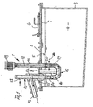
- a metering unit 1 which is designed as a crucible insert and can be introduced through the upper cover 2 of a crucible 3 in the molten metal 4, the level of which is maintained at level 5 by means not shown.
- the cover 2 of the crucible 3 is provided in a known manner with an opening 7 closed by a cover 6, through which material to be melted can be topped up.
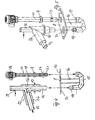
- the crucible insert 1 consists, as can be seen in particular from FIGS. 2 and 3, of a lid flange 8 which can be placed on the crucible cover 2 and which has passage openings 31, 32 for a pump tube 11 which can be inserted perpendicularly to the cover flange 8 or for a cover flange which is also perpendicular to the cover flange 8 insertable outlet pipe 12 is provided.
- the outlet pipe 12 is, as shown in FIGS. 1 and 2, approximately in half height with a kinking and slightly downwardly inclined outlet pipe 13 which forms an overflow edge for the supplied from the pump tube 11 from the melt material at its upper inner edge 13a.
- the lower end of the outlet pipe 12 is connected via a type of plug connection 14 to a U-shaped connecting tube 15, which in turn is connected via a tubular holder 16 fixed to the cover flange 8.
- the U-shaped connecting tube 15 has on the side of the pump tube 11 also has a plug-in connection 17, via which it is sealed to the lower end of the pump tube 11.
- a drive shaft 18 is rotatably mounted, which is displaceable by a drive motor 19 in rotation.
- the drive shaft 18 is provided at its lower end below a bearing 20 with a pump screw 21 or the like.
- a plurality of openings 23 are provided in the pump tube 11 distributed over the circumference, through which the melt 4 in the direction of the arrows 24 can enter into the tube interior.
- the melt is then conveyed through the connecting pipe 15 in the direction of the arrows 25 to the transition edge 13a and from there through the outlet pipe 13 to the pouring device, not shown. It is clear that by an appropriate loading of the drive motor 19 a precisely metered amount of melt can be discharged through the outlet pipe 13.
- the outlet pipe 12 is provided in the embodiment in the region of the cover flange 8 and up to the height of the outlet nozzle 13 with a jacket 26 of a heat insulation, in which also a heating in the form of electrical heating wires 27 or the like may be arranged.
- the temperature of the discharged melt can thus be maintained at a certain level until shortly before the transfer to the casting machine.
- the outlet pipe 12 is provided in the region above the outlet nozzle 13 with a feed nozzle 28 for the supply of a protective gas, so that in this way it can be prevented that the discharged melt on its way through the outlet pipe of the risk Oxidation is subjected.
- FIG. 3 shows that the outlet pipe 12 and the fixed outlet 13 connected to it in the direction of the arrows 29 is pivotally arranged about the axis 30, which coincides with the axis of the outlet pipe 12.
- the outlet pipe 12 including heat insulation 26 is pivotally held in the opening 31 of the cover flange 8, which takes place in each case by the arrangement of sleeves 9 or rings 10.
- the crucible insert 1 which can be used as a complete unit in the crucible 3 and can be fixed by means of its cover flange 8 on the crucible cover 2, from relatively easy to assemble, but also disassembled items exists, which on the one hand allow a simple construction of the dosing unit, on the other hand also easy maintenance and cleaning.
- a great advantage of this embodiment is that a change of the crucible itself is not necessary or only with respect to its cover. In the pump itself, no change in the melt level occurs during the pumping process. After overcoming the difference in height in the outlet pipe 12 between the level 5 and the transition edge 13a, the targeted dosing can take place. This outlet pipe 12 can, as Figs. 4 and 5 can be removed, easily disassemble for maintenance and clean.
Abstract
Description
Die Erfindung betrifft eine Vorrichtung zum Beschicken von Gießeinrichtungen mit Metallschmelze nach dem Oberbegriff des Anspruchs 1.The invention relates to a device for feeding pouring devices with molten metal according to the preamble of claim 1.
Eine Vorrichtung zum Beschicken von Gießeinrichtungen mit Metallschmelze, die einen Schmelzentiegel, eine in die Schmelze eintauchenden Dosierpumpe und ein Auslaufrohr umfasst, ist aus der DE-OS 2 111 462 bekannt. Dort ist der Schmelztiegel mit einem Zumessbehälter versehen, der an den Schmelztiegel angeschlossen ist. Vom Zumessbehälter aus führt durch die Wandung desselben ein Auslaufrohr schräg nach unten, dessen Innenkante einen Überlauf bildet, über den durch Eintauchen eines in der Art eines Plungers wirkenden Zumesskörpers die gewünschte Schmelzenmenge dosiert nach außen abgegeben werden kann.A device for feeding molten metal pouring devices comprising a crucible, a dosing pump immersed in the melt and an outlet pipe is known from DE-OS 2,111,462. There, the crucible is provided with a Zumessbehälter, which is connected to the crucible. From the metering tank leads through the wall of an outlet pipe obliquely downwards, the inner edge forms an overflow, can be dispensed dosed through the immersion of a force acting in the manner of a plunger metering body the desired amount of melt to the outside.
Aus der Patentschrift EP 817 691 B1 ist eine Vorrichtung bekannt, bei der ebenfalls das Auslaufrohr durch die Schmelztiegelwandung schräg nach unten und nach außen geführt ist. Dieses Auslaufrohr wird von einer Dosierpumpe beaufschlagt, die in den Entnahmeteil des Schmelztiegels eintaucht. Bei solchen Vorrichtung nach dem Stand der Technik wird ein Spezialtiegel erforderlich, in dessen Seitenwand das Auslaufrohr angeordnet wird. Da die Auslaufrohre starr mit dem Schmelztiegel verbunden sind, muss dieser zur Anpassung an die Füllbüchse einer entsprechenden Druckgießmaschine schwenkbar ausgeführt werden. Die Wartung solcher Einrichtungen ist überdies aufwendig. Dies gilt auch für die Dosierpumpe selbst, in der sich das Schmelzenniveau während des Dosiervorganges ändert.From the patent EP 817 691 B1 a device is known in which also the outlet pipe obliquely through the crucible wall is guided down and out. This outlet pipe is acted upon by a metering pump, which dips into the removal part of the crucible. In such a device according to the prior art, a special crucible is required, in whose side wall the outlet pipe is arranged. Since the outlet pipes are rigidly connected to the crucible, this must be made to adapt to the Füllbüchse a corresponding die casting machine pivotable. The maintenance of such facilities is also expensive. This also applies to the metering pump itself, in which the melt level changes during the dosing process.
Aus der Patentschrift DE 1 134 183 ist eine Beschickungsvorrichtung für Gießmaschinen bekannt, bei der die Pumpe schräg von oben durch die Schmelztiegelabdeckung in die Schmelze eingeführt ist und selbst an ihrem oberen Ende mit einer Auslauföffnung versehen ist. Diese Pumpe lässt sich auch höhenverschiebbar anordnen, aber die Anpassung an die entsprechenden Füllvorrichtungen von Druckgießmaschinen muss ebenfalls durch Anpassung der Tiegellage an die Druckgießmaschine vorgenommen werden. Eine notwendige Reinigung der Pumpe setzt den Stillstand der Füllvorrichtung voraus.From the patent DE 1 134 183 a charging device for casting machines is known in which the pump is introduced obliquely from above through the crucible cover in the melt and is itself provided at its upper end with an outlet opening. This pump can also be arranged vertically adjustable, but the adaptation to the corresponding filling devices of die casting machines must also be made by adjusting the crucible position to the die casting machine. A necessary cleaning of the pump requires the standstill of the filling device.
In der Offenlegungsschrift JP 2002-144013 A ist eine Vorrichtung der eingangs genannten Art offenbart, bei der sich das Auslaufrohr durch eine Tiegelabdeckung hindurch erstreckt und an dieser schwenkbar gehalten ist, während die Dosierpumpe durch einen separat vom Auslaufrohr an der Tiegelabdeckung gehaltenen Aufbau realisiert ist, der eine rotierende Motorwelle und einen axial beweglichen Kolbenschaft umfasst, die sich durch je eine Durchtrittsöffnung in der Tiegelabdeckung bzw. je einem zugehörigen Deckelflansch hindurch in den Schmelzentiegel erstrecken. Dabei ist der Kolbenschaft endseitig mit einem Kolben versehen, der in einem vertikalen zylindrischen Teil eines Pumpengehäuses geführt ist, welcher an der Unterseite der Tiegelabdeckung bzw. den Deckelflanschen angebracht ist und auf seiner anderen Seite mit dem Auslaufrohr in Verbindung steht.In the publication JP 2002-144013 A a device of the type mentioned is disclosed in which the outlet pipe extends through a crucible cover and is pivotally supported on this, while the metering pump is realized by a separately held from the outlet pipe to the crucible cover structure, which comprises a rotating motor shaft and an axially movable piston shaft, which extend through a respective passage opening in the crucible cover or depending on an associated cover flange into the crucible. In this case, the piston shaft is provided at the end with a piston which is guided in a vertical cylindrical part of a pump housing, which at the bottom of the crucible cover or the cover flanges is mounted and communicates with the outlet pipe on its other side.
In der Offenlegungsschrift JP 08-033971 A ist eine Vorrichtung der eingangs genannten Art offenbart, bei der die Dosiereinheit insgesamt direkt an einer Tiegelabdeckung festgelegt ist, wobei sich durch entsprechende Durchtrittsöffnungen in der Tiegelabdeckung das Auslaufrohr, ein axial beweglicher Kolbenschaft und Haltestangen hindurch erstrecken.In the patent document JP 08-033971 A discloses a device of the type mentioned, in which the metering unit is set in total directly on a crucible cover, which extend through corresponding passage openings in the crucible cover the outlet pipe, an axially movable piston skirt and support rods therethrough.
Der Erfindung liegt das technische Problem zugrunde, eine Vorrichtung der eingangs genannten Art so auszubilden, dass eine einfache Wartung und eine einfache Anpassung an die Gießmaschine möglich ist.The invention is based on the technical problem of designing a device of the type mentioned at the beginning in such a way that simple maintenance and simple adaptation to the caster are possible.
Die Erfindung löst dieses Problem durch die Bereitstellung einer Vorrichtung mit den Merkmalen des Anspruchs 1. Bei dieser Vorrichtung ragt das Auslaufrohr durch eine Tiegelabdeckung oder genauer gesagt durch einen an der Tiegelabdeckung befestigbaren Deckelflansch nach oben hindurch und ist schwenkbar in der Tiegelabdeckung, d.h. dem Deckelflansch, geführt. Eine solche Ausgestaltung macht, wenn das Auslauf rohr entsprechend lang ausgebildet ist, eine einfache Anpassung an die zugeordnete Gießeinrichtung möglich. Die Lage des Schmelzentiegels braucht nicht geändert zu werden.The invention solves this problem by providing a device having the features of claim 1. In this device, the spout protrudes upwardly through a crucible cover, or more precisely, through a cover flange attachable to the crucible cover, and is pivotally mounted in the crucible cover, i. the cover flange, guided. Such a configuration makes, if the outlet pipe is designed to be correspondingly long, a simple adaptation to the associated casting device possible. The position of the crucible does not need to be changed.
Dabei ist das Auslaufrohr Teil einer in die Tiegelabdeckung eingesetzten Dosiereinheit, die auch die Dosierpumpe umfasst. Die Dosierpumpe kann mit einem außerhalb der Tiegelabdeckung angeordneten Antriebsmotor versehen sein und nur mit ihrem Pumpenteil, d.h. also mit Saug- und Druckteil, in die Schmelze hereinragen.In this case, the outlet pipe is part of a metering unit used in the crucible cover, which also includes the metering pump. The metering pump may be provided with a drive motor disposed outside the crucible cover and only with its pump part, i. So with suction and pressure part, protrude into the melt.
In Ausgestaltung der Erfindung kann dabei die Druckseite der Dosierpumpe über ein U-förmiges Verbindungsrohr mit dem unteren Ende des Auslaufrohres verbunden sein, wobei das Verbindungsrohr über eine Halterung an einem Deckelflansch befestigt ist, der auf der Tiegelabdeckung sitzt.In an embodiment of the invention can be the pressure side of the metering pump via a U-shaped connecting pipe with the lower end of the Outlet pipe to be connected, wherein the connecting tube is attached via a bracket to a cover flange which sits on the crucible cover.
Dieser Deckelflansch kann in Ausgestaltung der Erfindung mit Durchtrittsbuchsen für das Auslaufrohr und für die Dosierpumpe versehen sein, so dass ein Tiegeleinsatz in der Form einer Baueinheit entsteht, der von oben durch die Tiegelabdeckung hindurch in relativ einfacher Weise dem Schmelztiegel zugeordnet werden kann.This cover flange can be provided in an embodiment of the invention with through bushings for the outlet pipe and for the metering pump, so that a crucible insert in the form of a unit is formed, which can be assigned to the crucible from above through the crucible cover in a relatively simple manner.
Das Auslaufrohr kann in weiterer Ausgestaltung mit einem etwa in halber Höhe seitlich abknickenden Auslaufstutzen versehen sein, wobei dann oberhalb des Auslaufstutzens eine Zuführöffnung für Schutzgas im Auslaufrohr vorgesehen ist. Diese Ausgestaltung verhindert, dass die entnommene Schmelze der Gefahr einer Oxidation unterworfen wird. Das Auslaufrohr kann im Bereich außerhalb der Tiegelabdeckung mindestens bis zum Auslaufstutzen mit einer Wärmeisolierung und mit einer Beheizungseinrichtung versehen sein, und in besonders vorteilhafter Ausgestaltung ist es möglich, das Verbindungsrohr mit hitzbeständigen Steckanschlüssen für die Druckseite der Dosierpumpe und für das Auslaufrohr auszugestalten. Diese Ausführung nämlich ermöglicht dann nach dem Ausbau des Tiegeleinsatzes eine leichte Demontage zum Zweck einer Reinigung von Pumpe, Auslaufrohr und Verbindungsrohr.The outlet pipe may be provided in a further embodiment with an approximately halfway up the side kinking outlet nozzle, in which case a supply opening for protective gas is provided in the outlet pipe above the outlet nozzle. This embodiment prevents the withdrawn melt is subjected to the risk of oxidation. The outlet pipe may be provided in the area outside the crucible cover at least to the outlet nozzle with a heat insulation and with a heating device, and in a particularly advantageous embodiment, it is possible to design the connecting pipe with heat-resistant plug-in connections for the pressure side of the metering pump and for the outlet pipe. Namely, this embodiment makes it possible after removal of the crucible insert easy disassembly for the purpose of cleaning the pump, outlet pipe and connecting pipe.
Die Erfindung ist anhand eines Ausführungsbeispieles in der Zeichnung dargestellt und wird im folgenden erläutert. Es zeigen:
- Fig. 1
- eine schematische Darstellung eines Längsschnittes durch einen Schmelztiegel mit einer nach der Erfindung ausgestalteten Dosiereinheit,
- Fig. 2
- die vergrößerte Darstellung eines Schnittes durch die Dosiereinrichtung der Fig. 1,
- Fig. 3
- die perspektivische Darstellung der Dosiereinheit nach Fig. 1,
- Fig. 4
- eine Explosionsdarstellung der für den Aufbau der Dosiereinheit verwendeten Teile und
- Fig. 5
- eine Explosionsdarstellung der Teile nach Fig. 4, jedoch in perspektivischer Darstellung.
- Fig. 1
- 1 is a schematic representation of a longitudinal section through a crucible with a metering unit designed according to the invention;
- Fig. 2
- the enlarged view of a section through the metering device of Fig. 1,
- Fig. 3
- the perspective view of the dosing unit of FIG. 1,
- Fig. 4
- an exploded view of the parts used for the construction of the dosing and
- Fig. 5
- an exploded view of the parts of FIG. 4, but in a perspective view.
Die Fig. 1 bis 3 zeigen eine Dosiereinheit 1, die als Tiegeleinsatz ausgebildet ist und durch die obere Abdeckung 2 eines Schmelztiegels 3 in die Metallschmelze 4 eingeführt werden kann, deren Niveau durch nicht gezeigte Mittel auf dem Pegel 5 gehalten wird. Die Abdeckung 2 des Tiegels 3 ist in bekannter Weise mit einer durch einen Deckel 6 geschlossenen Öffnung 7 versehen, durch welche zu schmelzendes Material nachgefüllt werden kann.1 to 3 show a metering unit 1, which is designed as a crucible insert and can be introduced through the
Der Tiegeleinsatz 1 besteht, wie insbesondere auch aus den Fig. 2 und 3 hervorgeht, aus einem auf die Tiegelabdeckung 2 aufsetzbaren Deckelflansch 8, der mit Durchtrittsöffnungen 31, 32 für ein senkrecht zum Deckelflansch 8 einführbares Pumpenrohr 11 bzw. für ein ebenfalls senkrecht zum Deckelflansch 8 einführbares Auslaufrohr 12 versehen ist. Das Auslaufrohr 12 ist dabei, wie die Fig. 1 und 2 zeigen, etwa in halber Höhe mit einem abknickenden und leicht nach unten geneigten Auslaufstutzen 13 versehen, der an seiner oberen Innenkante 13a eine Überlaufkante für das vom Pumpenrohr 11 aus gelieferte Schmelzenmaterial bildet. Das untere Ende des Auslaufrohres 12 ist über eine Art Steckanschluss 14 an ein U-förmiges Verbindungsrohr 15 angeschlossen, welches wiederum über eine rohrförmige Halterung 16 fest mit dem Deckelflansch 8 verbunden ist. Das U-förmige Verbindungsrohr 15 weist auf der Seite des Pumpenrohres 11 ebenfalls einen Steckanschluss 17 auf, über den es dicht mit dem unteren Ende des Pumpenrohres 11 verbunden ist.The crucible insert 1 consists, as can be seen in particular from FIGS. 2 and 3, of a
Die Figuren machen auch deutlich, dass im Pumpenrohr 11 eine Antriebswelle 18 drehbar gelagert ist, die von einem Antriebsmotor 19 in Rotation versetzbar ist. Die Antriebswelle 18 ist an ihrem unteren Ende unterhalb einer Lagerung 20 mit einer Pumpschnecke 21 oder dergleichen versehen. Oberhalb der Pumpschnecke sind im Pumpenrohr 11 auf dem Umfang verteilt mehrere Öffnungen 23 vorgesehen, durch welche die Schmelze 4 im Sinn der Pfeile 24 in das Rohrinnere eintreten kann. Die Schmelze wird dann durch das Verbindungsrohr 15 im Sinn der Pfeile 25 zur Übertrittskante 13a und von dort durch den Auslaufstutzen 13 zur nicht gezeigten Gießeinrichtung gefördert. Es wird deutlich, dass durch entsprechende Beaufschlagung des Antriebsmotors 19 eine genau dosierbare Menge an Schmelze durch den Auslaufstutzen 13 abgegeben werden kann.The figures also make clear that in the
Das Auslaufrohr 12 ist beim Ausführungsbeispiel im Bereich des Deckelflansches 8 und bis zur Höhe des Auslaufstutzens 13 mit einem Mantel 26 einer Wärmeisolierung versehen, in der auch noch eine Beheizung in Form elektrischer Heizdrähte 27 oder dergleichen angeordnet sein kann. Die Temperatur der abgegebenen Schmelze kann so bis kurz vor dem Übertritt in die Gießmaschine auf einem bestimmten Niveau gehalten werden.The
Wie die Figuren außerdem zeigen, ist das Auslaufrohr 12 im Bereich oberhalb des Auslaufstutzens 13 mit einem Zuführstutzen 28 für die Zufuhr eines Schutzgases versehen, so dass auf diese Weise auch verhindert werden kann, dass die abgegebene Schmelze auf ihrem Weg durch das Auslaufrohr der Gefahr einer Oxidation unterworfen wird.As the figures also show, the
Wesentlich ist, wie insbesondere Fig. 3 zeigt, dass das Auslaufrohr 12 und der fest mit ihm verbundene Auslaufstutzen 13 im Sinn der Pfeile 29 schwenkbar um die Achse 30 angeordnet ist, die mit der Achse des Auslaufrohres 12 zusammenfällt. Dies wird dadurch erreicht, dass das Auslaufrohr 12 einschließlich Wärmeisolierung 26 schwenkbar in der Öffnung 31 des Deckelflansches 8 gehalten ist, was jeweils durch die Anordnung von Muffen 9 oder Ringen 10 erfolgt.It is essential, in particular Fig. 3 shows that the
Die Fig. 4 und 5 machen nun zusätzlich deutlich, dass der Tiegeleinsatz 1, der als komplette Baueinheit in den Tiegel 3 einsetzbar ist und mit Hilfe seines Deckelflansches 8 auf der Tiegelabdeckung 2 befestigt werden kann, aus verhältnismäßig leicht zusammensetzbaren, aber auch wieder demontierbaren Einzelteilen besteht, die zum einen einen einfachen Aufbau der Dosiereinheit ermöglichen, zum anderen aber auch eine einfache Wartung und Reinigung. Ein großer Vorteil dieser Ausgestaltung ist es, dass eine Änderung des Tiegels selbst nicht oder nur bezüglich seiner Abdeckung notwendig ist. In der Pumpe selbst tritt während des Pumpvorganges keine Änderung des Schmelzniveaus ein. Nach dem Überwinden des Höhenunterschiedes im Auslaufrohr 12 zwischen dem Pegel 5 und der Übertrittskante 13a kann der gezielte Dosiervorgang stattfinden. Dieses Auslaufrohr 12 lässt sich, wie den Fig. 4 und 5 entnehmbar ist, für die Wartung leicht demontieren und reinigen.4 and 5 make now also clear that the crucible insert 1, which can be used as a complete unit in the
Der entscheidenste Vorteil ist, dass wegen der Schwenkbarkeit des Auslaufstutzens 13 im Sinn der Pfeile 29, eine Anpassung der Lage des Tiegels selbst an die entsprechende Gießmaschine nicht notwendig ist. Schließlich ist auch noch zu erwähnen, dass bei der gewählten Ausführung keine ungewollte Auslaufgefahr von Schmelze besteht, weil die Austrittsöffnungen oberhalb des Pegelniveaus 5 liegen. Die Ausgestaltung durch Steckanschlüsse und die Verbindung von Pumpe und Auslaufrohr mit dem Verbindungsrohr 15 ergeben einen einfachen Aufbau des gesamten Tiegeleinsatzes 1.The key advantage is that because of the pivoting of the
Claims (8)
- Device for charging casting devices with molten metal, having- a crucible (3) and a metering unit (1) comprising a metering pump (21, 23) with a pump part projecting into the crucible and a discharge pipe (12),characterized in that- the metering unit (1) is designed as a crucible insert having a cover flange (8) attachable to a cover (2) of the crucible (3), where the pump part projecting into the crucible (3) contains a pump pipe (11) that extends through an associated passage opening (32) of the cover flange and is connected to the discharge pipe (12), and the discharge pipe (12) is held swivellably in an associated passage opening (31) of the cover flange.
- Device according to Claim 1, characterized in that the metering pump is provided with a drive motor (19) arranged outside the crucible cover (2).
- Device according to Claim 1 or 2, characterized in that the discharge side of the metering pump is connected to the lower end of the discharge pipe (12) via a U-shaped connecting pipe (15).
- Device according to Claim 3, characterized in that the connecting pipe (15) is fastened to the cover flange (8) by a holder (16).
- Device according to one of Claims 1 to 4, characterized in that the discharge pipe (12) is provided about half way up with an outlet connection (13) projecting laterally from it.
- Device according to Claim 5, characterized in that a supply opening (28) for protective gas is provided in the discharge pipe (12) above the outlet connection (13).
- Device according to Claim 5 or 6, characterized in that the discharge pipe (12) is provided in the area outside the crucible cover (2) with a thermal insulation (26) and/or with a heating device (27) at least up to the outlet connection (13).
- Device according to one of Claims 3 to 7, characterized in that the connecting pipe (15) is provided with heat-resistant plug-in connections (17 and 14) for the pressure side of the metering pump (17, 18) and for the discharge pipe (12) respectively.
Priority Applications (7)
| Application Number | Priority Date | Filing Date | Title |
|---|---|---|---|
| EP03013322A EP1486277B1 (en) | 2003-06-13 | 2003-06-13 | Device for charging casting devices with molten metal |
| ES03013322T ES2279030T3 (en) | 2003-06-13 | 2003-06-13 | DEVICE FOR FEEDING MASSED METAL MASS TO COLADA DEVICES. |
| AT03013322T ATE347953T1 (en) | 2003-06-13 | 2003-06-13 | DEVICE FOR LOADING CASTING DEVICES WITH METAL MELTS |
| DE50305957T DE50305957D1 (en) | 2003-06-13 | 2003-06-13 | Apparatus for charging casting equipment with molten metal |
| US10/560,211 US7563406B2 (en) | 2003-06-13 | 2004-04-30 | Device for supplying casting installations with molten metal |
| CNB2004800165140A CN100352580C (en) | 2003-06-13 | 2004-04-30 | Device for filling casting installation with molten metal |
| PCT/EP2004/004581 WO2004110681A1 (en) | 2003-06-13 | 2004-04-30 | Device for supplying casting installations with molten metal |
Applications Claiming Priority (1)
| Application Number | Priority Date | Filing Date | Title |
|---|---|---|---|
| EP03013322A EP1486277B1 (en) | 2003-06-13 | 2003-06-13 | Device for charging casting devices with molten metal |
Publications (2)
| Publication Number | Publication Date |
|---|---|
| EP1486277A1 EP1486277A1 (en) | 2004-12-15 |
| EP1486277B1 true EP1486277B1 (en) | 2006-12-13 |
Family
ID=33185893
Family Applications (1)
| Application Number | Title | Priority Date | Filing Date |
|---|---|---|---|
| EP03013322A Expired - Lifetime EP1486277B1 (en) | 2003-06-13 | 2003-06-13 | Device for charging casting devices with molten metal |
Country Status (7)
| Country | Link |
|---|---|
| US (1) | US7563406B2 (en) |
| EP (1) | EP1486277B1 (en) |
| CN (1) | CN100352580C (en) |
| AT (1) | ATE347953T1 (en) |
| DE (1) | DE50305957D1 (en) |
| ES (1) | ES2279030T3 (en) |
| WO (1) | WO2004110681A1 (en) |
Cited By (2)
| Publication number | Priority date | Publication date | Assignee | Title |
|---|---|---|---|---|
| US7563406B2 (en) | 2003-06-13 | 2009-07-21 | Meltec Industriofenbau GmbH | Device for supplying casting installations with molten metal |
| EP2283950A1 (en) | 2009-08-12 | 2011-02-16 | Strikowestofen Gmbh | Method and device for dosing molten metal |
Families Citing this family (10)
| Publication number | Priority date | Publication date | Assignee | Title |
|---|---|---|---|---|
| EP1795283A1 (en) | 2005-12-06 | 2007-06-13 | Meltec Industrieofenbau GmbH | Device for charging foundry machines with metal melt |
| CN101337271B (en) * | 2007-07-08 | 2012-10-10 | 福建迪创投资有限公司 | Casting technique capable of melting, transferring and precisely quantitatively feeding metal and device thereof |
| JP5780608B2 (en) * | 2009-06-16 | 2015-09-16 | パイロテック インコーポレイテッド | Overflow vortex transfer system |
| EP2652167B1 (en) * | 2010-12-13 | 2015-04-08 | Posco | Continuous coating apparatus |
| CN102139366B (en) * | 2011-01-13 | 2012-10-31 | 河南中色赛尔工业炉有限公司 | Flexible hot molten metal transferring joint |
| CN102909357A (en) * | 2012-10-31 | 2013-02-06 | 重庆硕龙科技有限公司 | Quantitative pouring method of light alloy melt |
| CN103831424A (en) * | 2014-03-26 | 2014-06-04 | 深圳市鼎正鑫科技有限公司 | Automatic quantitative pouring pump of liquid aluminum alloy |
| CA2928650C (en) | 2015-05-01 | 2023-09-26 | Opta Minerals Inc. | Lance drive system |
| KR101879815B1 (en) * | 2016-03-18 | 2018-07-19 | 주식회사 고려다이캐스팅기계 | Supply pump for molten metals |
| CN106089733A (en) * | 2016-08-01 | 2016-11-09 | 江苏胜达科技有限公司 | Borax soln circulating pump |
Family Cites Families (6)
| Publication number | Priority date | Publication date | Assignee | Title |
|---|---|---|---|---|
| JP3179289B2 (en) * | 1994-07-22 | 2001-06-25 | 宇部興産株式会社 | Magnesium water heater |
| US5944496A (en) * | 1996-12-03 | 1999-08-31 | Cooper; Paul V. | Molten metal pump with a flexible coupling and cement-free metal-transfer conduit connection |
| CN2428243Y (en) * | 2000-06-15 | 2001-05-02 | 林利坤 | Melting furnace of press-casting forming machine |
| JP2002144013A (en) * | 2000-11-15 | 2002-05-21 | Toyo Mach & Metal Co Ltd | Die casting apparatus |
| ITTO20010288A1 (en) * | 2001-03-27 | 2002-09-27 | Teksid Spa | EQUIPMENT FOR THE TRANSFER OF LIQUID METALS FROM A WITHDRAWAL CONTAINER TO A COLLECTION CONTAINER. |
| DE50305957D1 (en) * | 2003-06-13 | 2007-01-25 | Meltec Industrieofenbau Gmbh | Apparatus for charging casting equipment with molten metal |
-
2003
- 2003-06-13 DE DE50305957T patent/DE50305957D1/en not_active Expired - Lifetime
- 2003-06-13 ES ES03013322T patent/ES2279030T3/en not_active Expired - Lifetime
- 2003-06-13 EP EP03013322A patent/EP1486277B1/en not_active Expired - Lifetime
- 2003-06-13 AT AT03013322T patent/ATE347953T1/en active
-
2004
- 2004-04-30 WO PCT/EP2004/004581 patent/WO2004110681A1/en active Application Filing
- 2004-04-30 CN CNB2004800165140A patent/CN100352580C/en not_active Expired - Fee Related
- 2004-04-30 US US10/560,211 patent/US7563406B2/en not_active Expired - Fee Related
Cited By (3)
| Publication number | Priority date | Publication date | Assignee | Title |
|---|---|---|---|---|
| US7563406B2 (en) | 2003-06-13 | 2009-07-21 | Meltec Industriofenbau GmbH | Device for supplying casting installations with molten metal |
| EP2283950A1 (en) | 2009-08-12 | 2011-02-16 | Strikowestofen Gmbh | Method and device for dosing molten metal |
| DE102009037368A1 (en) | 2009-08-12 | 2011-02-17 | Strikowestofen Gmbh | Method and apparatus for dosing molten metal |
Also Published As
| Publication number | Publication date |
|---|---|
| DE50305957D1 (en) | 2007-01-25 |
| US7563406B2 (en) | 2009-07-21 |
| CN100352580C (en) | 2007-12-05 |
| ATE347953T1 (en) | 2007-01-15 |
| EP1486277A1 (en) | 2004-12-15 |
| US20070074844A1 (en) | 2007-04-05 |
| CN1805809A (en) | 2006-07-19 |
| ES2279030T3 (en) | 2007-08-16 |
| WO2004110681A1 (en) | 2004-12-23 |
Similar Documents
| Publication | Publication Date | Title |
|---|---|---|
| EP1486277B1 (en) | Device for charging casting devices with molten metal | |
| EP0711616B1 (en) | Device for casting metals | |
| WO2011151007A1 (en) | Method for tilt casting components and tilt casting device | |
| DE2245768B2 (en) | Device for pouring a metered amount of molten metal | |
| DE3906645C2 (en) | ||
| DE1758553A1 (en) | Foundry equipment | |
| DE1508928A1 (en) | Method and device for the continuous casting of hollow metal pipes | |
| DE1920605C3 (en) | Automatic scooping and dispensing device for liquid metals on die casting machines | |
| DE1458133A1 (en) | Continuous metal casting process and equipment for its implementation | |
| DE3214922C2 (en) | Low-pressure casting device for casting liquid metals | |
| DE2530785C3 (en) | Device for introducing aggregates into iron melts | |
| DE3221432A1 (en) | DEVICE FOR DEVELOPING PHOTOMATERIAL IN A ROTATING DRUM | |
| DE1908316A1 (en) | Die casting machine | |
| DE102008039211A1 (en) | Pipe target with end block for coolant supply | |
| EP0081475A2 (en) | Apparatus for discharging material at a high temperature from a vessel, especially sponge iron from a shaft furnace | |
| DE3050183C2 (en) | Dosing device for conveying liquid metal | |
| DE3023261C2 (en) | Mouthpiece for the end of a delivery line of a metering device for delivering liquid metal | |
| DE102018106078A1 (en) | staghorn | |
| DE1427912B2 (en) | Device for applying cooling liquid to a heated metal strip in a rolling mill | |
| DE3012047C2 (en) | Dosing device for conveying liquid metal | |
| DE2048328C (en) | Device for dispensing molten metal from a reservoir to a casting machine | |
| EP0693338A1 (en) | Refractory closing element for a closure device of molten metal-containing vessel with an outlet nozzle | |
| DE2848248C2 (en) | Centrifugal casting machine, especially for casting steel | |
| EP1795283A1 (en) | Device for charging foundry machines with metal melt | |
| DE2455743A1 (en) | Automatic casting of accumulator grids - where rotary pump forces molten lead up feeder pipe to metering valve |
Legal Events
| Date | Code | Title | Description |
|---|---|---|---|
| PUAI | Public reference made under article 153(3) epc to a published international application that has entered the european phase |
Free format text: ORIGINAL CODE: 0009012 |
|
| AK | Designated contracting states |
Kind code of ref document: A1 Designated state(s): AT BE BG CH CY CZ DE DK EE ES FI FR GB GR HU IE IT LI LU MC NL PT RO SE SI SK TR |
|
| AX | Request for extension of the european patent |
Extension state: AL LT LV MK |
|
| 17P | Request for examination filed |
Effective date: 20050603 |
|
| AKX | Designation fees paid |
Designated state(s): AT BE BG CH CY CZ DE DK EE ES FI FR GB GR HU IE IT LI LU MC NL PT RO SE SI SK TR |
|
| GRAP | Despatch of communication of intention to grant a patent |
Free format text: ORIGINAL CODE: EPIDOSNIGR1 |
|
| GRAS | Grant fee paid |
Free format text: ORIGINAL CODE: EPIDOSNIGR3 |
|
| GRAA | (expected) grant |
Free format text: ORIGINAL CODE: 0009210 |
|
| RAP1 | Party data changed (applicant data changed or rights of an application transferred) |
Owner name: MELTEC INDUSTRIEOFENBAU GMBH |
|
| AK | Designated contracting states |
Kind code of ref document: B1 Designated state(s): AT BE BG CH CY CZ DE DK EE ES FI FR GB GR HU IE IT LI LU MC NL PT RO SE SI SK TR |
|
| PG25 | Lapsed in a contracting state [announced via postgrant information from national office to epo] |
Ref country code: CZ Free format text: LAPSE BECAUSE OF FAILURE TO SUBMIT A TRANSLATION OF THE DESCRIPTION OR TO PAY THE FEE WITHIN THE PRESCRIBED TIME-LIMIT Effective date: 20061213 Ref country code: SI Free format text: LAPSE BECAUSE OF FAILURE TO SUBMIT A TRANSLATION OF THE DESCRIPTION OR TO PAY THE FEE WITHIN THE PRESCRIBED TIME-LIMIT Effective date: 20061213 Ref country code: RO Free format text: LAPSE BECAUSE OF FAILURE TO SUBMIT A TRANSLATION OF THE DESCRIPTION OR TO PAY THE FEE WITHIN THE PRESCRIBED TIME-LIMIT Effective date: 20061213 Ref country code: FI Free format text: LAPSE BECAUSE OF FAILURE TO SUBMIT A TRANSLATION OF THE DESCRIPTION OR TO PAY THE FEE WITHIN THE PRESCRIBED TIME-LIMIT Effective date: 20061213 Ref country code: SK Free format text: LAPSE BECAUSE OF FAILURE TO SUBMIT A TRANSLATION OF THE DESCRIPTION OR TO PAY THE FEE WITHIN THE PRESCRIBED TIME-LIMIT Effective date: 20061213 Ref country code: IE Free format text: LAPSE BECAUSE OF FAILURE TO SUBMIT A TRANSLATION OF THE DESCRIPTION OR TO PAY THE FEE WITHIN THE PRESCRIBED TIME-LIMIT Effective date: 20061213 Ref country code: NL Free format text: LAPSE BECAUSE OF FAILURE TO SUBMIT A TRANSLATION OF THE DESCRIPTION OR TO PAY THE FEE WITHIN THE PRESCRIBED TIME-LIMIT Effective date: 20061213 Ref country code: DK Free format text: LAPSE BECAUSE OF FAILURE TO SUBMIT A TRANSLATION OF THE DESCRIPTION OR TO PAY THE FEE WITHIN THE PRESCRIBED TIME-LIMIT Effective date: 20061213 |
|
| REG | Reference to a national code |
Ref country code: GB Ref legal event code: FG4D Free format text: NOT ENGLISH |
|
| REG | Reference to a national code |
Ref country code: CH Ref legal event code: EP |
|
| REG | Reference to a national code |
Ref country code: IE Ref legal event code: FG4D Free format text: LANGUAGE OF EP DOCUMENT: GERMAN |
|
| REF | Corresponds to: |
Ref document number: 50305957 Country of ref document: DE Date of ref document: 20070125 Kind code of ref document: P |
|
| PG25 | Lapsed in a contracting state [announced via postgrant information from national office to epo] |
Ref country code: BG Free format text: LAPSE BECAUSE OF FAILURE TO SUBMIT A TRANSLATION OF THE DESCRIPTION OR TO PAY THE FEE WITHIN THE PRESCRIBED TIME-LIMIT Effective date: 20070313 Ref country code: SE Free format text: LAPSE BECAUSE OF FAILURE TO SUBMIT A TRANSLATION OF THE DESCRIPTION OR TO PAY THE FEE WITHIN THE PRESCRIBED TIME-LIMIT Effective date: 20070313 |
|
| GBT | Gb: translation of ep patent filed (gb section 77(6)(a)/1977) |
Effective date: 20070329 |
|
| PG25 | Lapsed in a contracting state [announced via postgrant information from national office to epo] |
Ref country code: PT Free format text: LAPSE BECAUSE OF FAILURE TO SUBMIT A TRANSLATION OF THE DESCRIPTION OR TO PAY THE FEE WITHIN THE PRESCRIBED TIME-LIMIT Effective date: 20070514 |
|
| NLV1 | Nl: lapsed or annulled due to failure to fulfill the requirements of art. 29p and 29m of the patents act | ||
| EN | Fr: translation not filed | ||
| REG | Reference to a national code |
Ref country code: ES Ref legal event code: FG2A Ref document number: 2279030 Country of ref document: ES Kind code of ref document: T3 |
|
| PLBE | No opposition filed within time limit |
Free format text: ORIGINAL CODE: 0009261 |
|
| STAA | Information on the status of an ep patent application or granted ep patent |
Free format text: STATUS: NO OPPOSITION FILED WITHIN TIME LIMIT |
|
| 26N | No opposition filed |
Effective date: 20070914 |
|
| BERE | Be: lapsed |
Owner name: MELTEC INDUSTRIEOFENBAU GMBH Effective date: 20070630 |
|
| PG25 | Lapsed in a contracting state [announced via postgrant information from national office to epo] |
Ref country code: MC Free format text: LAPSE BECAUSE OF NON-PAYMENT OF DUE FEES Effective date: 20070630 |
|
| REG | Reference to a national code |
Ref country code: CH Ref legal event code: PL |
|
| PG25 | Lapsed in a contracting state [announced via postgrant information from national office to epo] |
Ref country code: BE Free format text: LAPSE BECAUSE OF NON-PAYMENT OF DUE FEES Effective date: 20070630 |
|
| PG25 | Lapsed in a contracting state [announced via postgrant information from national office to epo] |
Ref country code: GR Free format text: LAPSE BECAUSE OF FAILURE TO SUBMIT A TRANSLATION OF THE DESCRIPTION OR TO PAY THE FEE WITHIN THE PRESCRIBED TIME-LIMIT Effective date: 20070314 Ref country code: CH Free format text: LAPSE BECAUSE OF NON-PAYMENT OF DUE FEES Effective date: 20070630 Ref country code: FR Free format text: LAPSE BECAUSE OF FAILURE TO SUBMIT A TRANSLATION OF THE DESCRIPTION OR TO PAY THE FEE WITHIN THE PRESCRIBED TIME-LIMIT Effective date: 20070803 Ref country code: LI Free format text: LAPSE BECAUSE OF NON-PAYMENT OF DUE FEES Effective date: 20070630 |
|
| PG25 | Lapsed in a contracting state [announced via postgrant information from national office to epo] |
Ref country code: FR Free format text: LAPSE BECAUSE OF FAILURE TO SUBMIT A TRANSLATION OF THE DESCRIPTION OR TO PAY THE FEE WITHIN THE PRESCRIBED TIME-LIMIT Effective date: 20061213 |
|
| PG25 | Lapsed in a contracting state [announced via postgrant information from national office to epo] |
Ref country code: EE Free format text: LAPSE BECAUSE OF FAILURE TO SUBMIT A TRANSLATION OF THE DESCRIPTION OR TO PAY THE FEE WITHIN THE PRESCRIBED TIME-LIMIT Effective date: 20061213 |
|
| PG25 | Lapsed in a contracting state [announced via postgrant information from national office to epo] |
Ref country code: CY Free format text: LAPSE BECAUSE OF FAILURE TO SUBMIT A TRANSLATION OF THE DESCRIPTION OR TO PAY THE FEE WITHIN THE PRESCRIBED TIME-LIMIT Effective date: 20061213 Ref country code: LU Free format text: LAPSE BECAUSE OF NON-PAYMENT OF DUE FEES Effective date: 20070613 |
|
| PG25 | Lapsed in a contracting state [announced via postgrant information from national office to epo] |
Ref country code: TR Free format text: LAPSE BECAUSE OF FAILURE TO SUBMIT A TRANSLATION OF THE DESCRIPTION OR TO PAY THE FEE WITHIN THE PRESCRIBED TIME-LIMIT Effective date: 20061213 Ref country code: HU Free format text: LAPSE BECAUSE OF FAILURE TO SUBMIT A TRANSLATION OF THE DESCRIPTION OR TO PAY THE FEE WITHIN THE PRESCRIBED TIME-LIMIT Effective date: 20070614 |
|
| PGFP | Annual fee paid to national office [announced via postgrant information from national office to epo] |
Ref country code: ES Payment date: 20120628 Year of fee payment: 10 |
|
| PGFP | Annual fee paid to national office [announced via postgrant information from national office to epo] |
Ref country code: GB Payment date: 20130620 Year of fee payment: 11 |
|
| PGFP | Annual fee paid to national office [announced via postgrant information from national office to epo] |
Ref country code: IT Payment date: 20130621 Year of fee payment: 11 |
|
| GBPC | Gb: european patent ceased through non-payment of renewal fee |
Effective date: 20140613 |
|
| PG25 | Lapsed in a contracting state [announced via postgrant information from national office to epo] |
Ref country code: IT Free format text: LAPSE BECAUSE OF NON-PAYMENT OF DUE FEES Effective date: 20140613 |
|
| PG25 | Lapsed in a contracting state [announced via postgrant information from national office to epo] |
Ref country code: GB Free format text: LAPSE BECAUSE OF NON-PAYMENT OF DUE FEES Effective date: 20140613 |
|
| REG | Reference to a national code |
Ref country code: ES Ref legal event code: FD2A Effective date: 20150728 |
|
| PG25 | Lapsed in a contracting state [announced via postgrant information from national office to epo] |
Ref country code: ES Free format text: LAPSE BECAUSE OF NON-PAYMENT OF DUE FEES Effective date: 20140614 |
|
| PGFP | Annual fee paid to national office [announced via postgrant information from national office to epo] |
Ref country code: DE Payment date: 20160617 Year of fee payment: 14 |
|
| PGFP | Annual fee paid to national office [announced via postgrant information from national office to epo] |
Ref country code: AT Payment date: 20160620 Year of fee payment: 14 |
|
| REG | Reference to a national code |
Ref country code: DE Ref legal event code: R119 Ref document number: 50305957 Country of ref document: DE |
|
| REG | Reference to a national code |
Ref country code: AT Ref legal event code: MM01 Ref document number: 347953 Country of ref document: AT Kind code of ref document: T Effective date: 20170613 |
|
| PG25 | Lapsed in a contracting state [announced via postgrant information from national office to epo] |
Ref country code: DE Free format text: LAPSE BECAUSE OF NON-PAYMENT OF DUE FEES Effective date: 20180103 |
|
| PG25 | Lapsed in a contracting state [announced via postgrant information from national office to epo] |
Ref country code: AT Free format text: LAPSE BECAUSE OF NON-PAYMENT OF DUE FEES Effective date: 20170613 |