EP1485967B1 - Verfahren und vorrichtung zur nachfuehrung einer antenne - Google Patents
Verfahren und vorrichtung zur nachfuehrung einer antenne Download PDFInfo
- Publication number
- EP1485967B1 EP1485967B1 EP03714757A EP03714757A EP1485967B1 EP 1485967 B1 EP1485967 B1 EP 1485967B1 EP 03714757 A EP03714757 A EP 03714757A EP 03714757 A EP03714757 A EP 03714757A EP 1485967 B1 EP1485967 B1 EP 1485967B1
- Authority
- EP
- European Patent Office
- Prior art keywords
- antenna
- polarization
- signal level
- reception
- main
- Prior art date
- Legal status (The legal status is an assumption and is not a legal conclusion. Google has not performed a legal analysis and makes no representation as to the accuracy of the status listed.)
- Expired - Lifetime
Links
Images


Classifications
-
- H—ELECTRICITY
- H01—ELECTRIC ELEMENTS
- H01Q—ANTENNAS, i.e. RADIO AERIALS
- H01Q1/00—Details of, or arrangements associated with, antennas
- H01Q1/12—Supports; Mounting means
- H01Q1/125—Means for positioning
- H01Q1/1257—Means for positioning using the received signal strength
-
- H—ELECTRICITY
- H01—ELECTRIC ELEMENTS
- H01Q—ANTENNAS, i.e. RADIO AERIALS
- H01Q1/00—Details of, or arrangements associated with, antennas
- H01Q1/12—Supports; Mounting means
- H01Q1/125—Means for positioning
Definitions
- the invention relates to a method and a device for tracking an antenna to receive orthogonal polarized transmission signals according to the preamble of the claim 1 or 9.
- satellite antennas have to receive according to programs broadcast via satellites be aligned exactly to a satellite. This is basically possible in vehicles even if this are in parked position. Problems exist however, if, for example, satellite programs to be received in moving objects, ie while a car or bus ride, a train ride on Ships or in airplanes.
- the cost expense is also not inconsiderable.
- the disadvantage is that the signal level of the satellite never optimally exploited can be, because by the pendulum motion, the main radiation direction or main lobe of the antenna for optimal alignment must be brought out, leading to the undesirable Drop of the signal level leads.
- a further device for receiving a satellite signal become known, for example, on trucks can be installed.
- cornering the Determination of an azimuthal angle deviation between the Direction of arrival of the satellite signal and the direction of reception the antenna by measuring the strength of the received Satellite signal.
- the antenna will also, as in the aforementioned prior art, after adjustment their elevation angle around their vertical Axis pivoted back and forth until the received Satellite signal reaches a maximum value. Does that happen? received satellite signal again, because the antenna for example, as a result of cornering of the land vehicle is turned away from the receiving direction of the satellite, the antenna is again pivoted about its vertical axis, until the received satellite signal again reaches a maximum value. Because with this azimuthal tracking the antenna at a drop in the received Satellite signal does not determine which Direction the antenna must be swiveled, this must be always be tried by swinging back and forth. If the received satellite signal continues to fall, that was Pivoting direction wrong.
- the direction of the azimuthal tracking of the antenna To be able to determine, it is preferably proposed that Antenna at a small angle about its vertical axis pivot after the direction of incidence of the satellite signal has been found.
- This azimuthal angle deviation the receiving direction of the antenna from the direction of incidence the satellite signal can be chosen so small be that the strength of the received satellite signal is above a minimum value, which is still one Image and sound reception should ensure.
- the antenna will never be in the optimal reception direction operated. This raises problems especially when the vehicle is in a receiving area, in which the satellite signal from home already weaker.
- the object of the present invention is therefore based on an improved from the last-mentioned prior art Tracking system especially for satellites with dual polarized transmit signals to create so before
- a satellite antenna i. especially one Flat antenna to achieve a high reception / signal level optimally aligned to a satellite.
- a change in direction e.g. of a vehicle with respect to a targeted Satellites safe to detect the antenna system targeted and thus drive-friendly actually to track to a maximum reception level.
- the invention is based on the following preliminary considerations on.
- Satellites transmit orthogonally polarized signals.
- a Satellite receiving antenna is capable of doing this orthogonal polarizations of a given frequency band (often a lower or upper frequency band) receive.
- a given frequency band often a lower or upper frequency band
- For linear polarizations one calls the both orthogonal polarizations with horizontal, though the E vector is horizontal to the earth, i. parallel to the horizon runs. From a vertical polarization is spoken when the E vector of the polarized electromagnetic Wave perpendicular to the earth, i. perpendicular to Horizon passes.
- At a circular polarization are the two orthogonal polarizations circularly clockwise or counter-clockwise.
- an antenna is now constructed so that the main beam directions, i. the main lobes for the respective polarization differ from each other.
- the antenna is left to e.g. in the azimuth plane squinting at a defined angle, i. that the Axes of the main lobes of the two orthogonal polarizations in the azimuth plane from each other by a defined Deviate angle.
- This allows, for example, that the main beam direction or the main lobe of the antenna or the feed system with respect to the H-polarization the desired satellite is aligned and in contrast the second polarization, in this case the V-polarization corresponding signals from the same satellite receives, but in the steeper flank area of the Main lobe.
- a deviation of the antenna alignment can now easily and accurately detected, since already a slight deviation with respect to an optimal Alignment of the antenna to the satellite with respect to the second polarization to a much greater signal level drop or a much stronger signal level rise leads, as this for the optimally aligned Polarization could be detected.
- a squint angle of for example, 0.2 ° - 2.0 °, preferably 0.4 ° - 1.0 ° full is sufficient. Because optimal conditions are always then reached when level differences of the detected polarization per angle change are as large as possible, thereby but the absolute reception level is not too small, so that the level difference is easy to detect. With In other words, so the squinting angle should be set be that - if the antenna with respect to the one actively received polarization is optimally aligned - the second to detect alignment and tracking received signal levels of the second polarization, for example has a signal level difference of 4 to 5 dB.
- the direction of the readjustment recognizable is.
- a level increase of the detected received signal one polarization indicates that the antenna from the non-squint position toward the detected one squinting position must be adjusted. there even the angle range can be adjusted by the level difference determine. From the level deviation can ultimately even derived an adjustment angle or a specific one Adjustment angle assigned to a specific level deviation become.
- the antenna can easily readjust without the Reception is impaired.
- the post-regulations only required if a misalignment actually to correct. As long as the detected signal the polarization evaluated for tracking no Signal level change, the entire system can in Rest remain, so that no motor drive for the tracking must be activated. This will be the total load of the rotationally driven mechanics significantly minimized in the prior art.
- an alignment or readjustment in the elevation direction also at greater intervals be made in the system according to the invention.
- AGC Anatenna Gain Control
- Figure 1 is a schematic representation of a geostationary Satellite 1 reproduced. About this satellite the programs are orthogonal to each other over at least two sent stationary polarization planes.
- This flat antenna 3 ' is, for example, on or in provided a moving object, such as a Motor vehicle, bus, ship or the like.
- the antenna 3 must always track so that ensures optimal program reception becomes.
- the antenna 3 with a tracking system 7 explained below (FIG. 2), So in the broadest sense with an evaluation and succession control device 7, about which a drive device 9 for alignment of the antenna 3 driven can be.
- This drive device 9 comprises at least a vertical axis of rotation 11 around which by means of the evaluation and control device, so ultimately by means of the tracking system 7 and the corresponding drive device 9 ', a tracking of the antenna 3 in Azimuth direction is enabled.
- a horizontal axis of rotation 13 is provided, to the antenna 3 also by means of another drive device 9 "in the elevation direction can.
- the antenna 3 including an associated feed system is constructed so that the main beam directions of the two polarizations differ, with others Words so the main radiation direction K1 for the horizontal Polarization with respect to the main radiation direction K2 for the vertical polarization V at a defined angle ⁇ to each other.
- This can be, for example in the case of a flat antenna by appropriate measures in realize the information networks.
- the result is therefore for the vertical Polarization V a level difference of about -5 dB.
- the entire setting is thus advantageously so chosen that level differences of the detected polarization per angle change are large, the absolute reception level but not too small, hence the level difference still easy to detect.
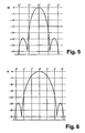
- such an antenna is in perspective Illustration indicated, including a three-dimensional representation of the main radiation direction or main lobe (partially reproduced in section).
- Elevation diagram yields the small one Half width in azimuth direction (in which the above explained, if necessary, each carried out readjustment or tracking the antenna carried out on the satellite becomes) and the comparatively large half width in the elevation direction, where it usually barely to a relevant signal level deterioration comes.
- a still improved solution offers itself then if, in addition, a location system, for example exists in the form of a GPS receiver. deviations the elevation basic settings for the respective receiving location can then be passed through this GPS receiver easily find out the necessary information then be delivered to the tracking system. A corresponding readjustment as described above is then unnecessary.
- An evaluation of the level differences can then be very simple by measuring the AGC, ie the Antenna Gain Control Signals are carried through the frontend.
- a downstream one AD converter can provide the appropriate information a microprocessor as part of the tracking system, i.e. as part of the evaluation and control device.
Landscapes
- Variable-Direction Aerials And Aerial Arrays (AREA)
- Details Of Aerials (AREA)
- Aerials With Secondary Devices (AREA)
- Radio Relay Systems (AREA)
Description
- Figur 1:
- eine schematische Darstellung eines Satelliten sowie einer Satelliten-Empfangsantenne;
- Figur 2:
- eine schematische Darstellung des erfindungsgemäßen Trackingsystems mit einer Auswert-, Kontroll- und/oder Steuerungseinrichtung;
- Figur 3:
- ein Diagramm bezüglich der schielenden Ausrichtung der beiden Hauptstrahlrichtungen der Antenne zur Verdeutlichung des Empfangs-Signalpegels;
- Figur 4:
- eine schematische perspektivische Darstellung einer Flachantenne mit unterschiedlicher Erstreckung in Horizontal- und Vertikalrichtung;
- Figur 5:
- ein Azimutdiagramm bezüglich der in Figur 3 wiedergegebenen Flachantenne; und
- Figur 6:
- ein Elevationsdiagramm.
Claims (16)
- Verfahren zur Nachführung einer auf oder in einem bewegten Objekt befindlichen Antenne auf einen Sender, insbesondere einen Satelliten, der Signale in zwei orthogonal zueinander ausgerichteten Polarisationen ausstrahlt, gekennzeichnet durch die folgenden Merkmale:es werden Antennen verwendet, deren beide Hauptstrahlrichtungen (K1, K2) oder Hauptkeulen (HK, VK) bezüglich der beiden empfangenen orthogonalen Polarisationen (H, V) zueinander einen divergierenden Schielwinkel (α) aufweisen,die Nachführung der Antenne (3) zum Empfang von über die horizontale Polarisation (H) ausgestrahlten Programmen erfolgt in Abhängigkeit des Empfangs-Signalpegels (19') und/oder der Empfangs-Signalpegel-Unterschiede (19') der weiteren detektierten vertikalen Polarisation (V), unddie Ausrichtung und Nachführung der Antenne (3) zum Empfang von über die vertikale Polarisation (V) ausgestrahlten Programmen erfolgt in Abhängigkeit des Empfangs-Signalpegels (17') und/oder der Empfangs-Signalpegelunterschiede (17') der weiteren detektierten horizontalen Polarisation (H).
- Verfahren nach Anspruch 1, dadurch gekennzeichnet, dass eine Antenne mit einem Schielwinkel (α) zwischen den beiden Hauptkeulen (HK, VK) zum Empfang der beiden Polarisationen (H, V) verwendet wird, derart, dass der der Detektion für die Nachführung der Antenne dienende Empfangs-Signalpegel (19') der einen Polarisation um etwa 2 bis 8 dB, vorzugsweise um etwa 4 bis 5 dB niedriger liegt als der Empfangs-Signalpegel (17') der auf optimalen Empfang nachgeführten anderen Polarisation (H, V) der Antenne (3).
- Verfahren nach Anspruch 1 oder 2, dadurch gekennzeichnet, dass zwischen den beiden Polarisationen (H, V) ein Schielwinkel (α) verwendet wird, derart, dass der empfangene Signalpegel (17', 19') der der Detektion für die Nachführung der Antenne (3) dienenden Polarisation (V, H) im Flankenbereich (15) der Hauptkeule (HK oder VK) liegt.
- Verfahren nach einem der Ansprüche 1 bis 3, dadurch gekennzeichnet, dass bei einem Anstieg des Empfang-Signalpegels (17', 19'), der der Detektion der schielenden Polarisation dient, die Antenne (3) so verstellt wird, dass die Hauptstrahlrichtung (K1, K2) oder Hauptkeule (HK, VK) der für den Empfang eines Programmes dienenden nachzuführenden Polarisation (H, V) in Richtung der der Detektion dienenden schielenden Polarisation (H, V) verstellt wird.
- Verfahren nach einem der Ansprüche 1 bis 4, dadurch gekennzeichnet, dass bei einem Absinken des Empfangs-Signalpegels (17', 19'), der der Detektion der schielenden Polarisation dient, die Antenne (3) so verstellt wird, dass die Hauptstrahlrichtung oder Hauptkeule der dem Empfang eines Programmes dienenden nachzuführenden Polarisation (H, V) von der der Detektion dienenden schielenden Polarisation (H, V) weg verstellt wird.
- Verfahren nach einem der Ansprüche 1 bis 5, dadurch gekennzeichnet, dass eine Flachantenne (3, 3') verwendet wird.
- Verfahren nach Anspruch 6, dadurch gekennzeichnet, dass eine Flachantenne (3, 3') mit einem Summationsnetzwerk verwendet wird, das so eingestellt ist, dass die Hauptrichtungen (K1, K2) oder Hauptkeulen (HK, VK) zum Empfangen der beiden orthogonalen Polarisationen (H, V) in einem definierten Schielwinkel (α) zueinander ausgerichtet sind.
- Verfahren nach einem der Ansprüche 1 bis 7, dadurch gekennzeichnet, dass eine Flachantenne (3, 3') verwendet wird, deren Azimuterstreckung gegenüber der Elevationserstreckung groß dimensioniert ist, also in Azimutrichtung eine Längserstreckung aufweist, die zumindest dreimal so groß, vorzugsweise viermal so groß ist wie in Elevationsrichtung.
- Vorrichtung zur Nachführung einer auf oder in einem bewegten Objekt befindlichen Antenne auf einen Sender, insbesondere einen Satelliten, der Signale in zwei orthogonal zueinander ausgerichteten Polarisationen ausstrahlt, mit einer Auswerte-, Kontroll- und/oder Steuerungseinrichtung (7) zur Nachführung der Antenne (3) um zumindest eine Achse in Azimutrichtung, gekennzeichnet durch die folgenden weiteren Merkmaledie Antenne (3, 3') und/oder das Speisesystem sind so aufgebaut, dass die beiden Hauptstrahlrichtungen (K1, K2) oder Hauptkeulen (HK, VK) der beiden empfangenen orthogonalen Polarisationen (H, V) in einem Schielwinkel (α) zueinander divergierend verlaufen,über die Auswerte-, Kontroll- und/oder Steuerungseinrichtung (7) wird der Signalpegel (19', 17') und/oder der jeweils schielend eingestellten Hauptkeule (VK oder HK) bezüglich der zugehörigen, empfangenen Polarisation (V oder H) und die sich ergebende Signalpegelveränderung so ausgewertet, dass die jeweils andere Polarisation (H oder V), über die ein jeweils aktuell gewünschtes Programm empfangen wird, gegenüber dem Signal-Empfangspegel (19' oder 17') der schielend eingestellten Polarisation einen höheren Signalpegel (17' oder 19'), vorzugsweise einen maximalen Signalpegel (17' oder 19') aufweist.
- Vorrichtung nach Anspruch 9, dadurch gekennzeichnet, dass der Schielwinkel (α) zwischen den beiden Polarisationen (H, V) bzw. zwischen den Hauptstrahlrichtungen (K1, K2) und/oder den beiden Hauptkeulen (HK, VK) so vorgesehen ist, dass der der Detektion für die Nachführung der Antenne (3) dienende Empfangs-Signalpegel (19', 17') um etwa 2 bis 8 dB, vorzugsweise um etwa 4 bis 5 dB niedriger liegt als der Empfangs-Signalpegel (17', 19') der auf optimalem Empfang nachgeführten Hauptkeule (HK oder VK) der Antenne(3).
- Vorrichtung nach Anspruch 9 oder 10, dadurch gekennzeichnet, dass der Schielwinkel (α) zwischen den beiden Polarisationen (H, V) bzw. den beiden Hauptstrahlrichtungen (K1, K2) der Hauptkeulen (HK, VK) so vorgesehen ist, dass der empfangene Signalpegel (17' oder 19') der der Detektion für die Nachführung der Antenne (3) dienenden Polarisation im Flankenbereich (15) der Hauptkeule (VK, HK) liegt.
- Vorrichtung nach einem der Ansprüche 9 bis 11, dadurch gekennzeichnet, dass bei einem Anstieg des Empfang-Signalpegels (19' oder 17') der der Detektion dienenden schielend eingestellten Polarisation die Antenne (3) so verstellbar ist, dass die für den Empfang eines Programms dienende nachzuführende Hauptstrahlrichtung (K1 oder K2) einer Hauptkeule (HK oder VK) in Richtung der der Detektion dienenden schielenden Hauptstrahlrichtung (K2 oder K1) der Hauptkeule (VK oder HK) der weiteren Polarisation (V, H) verstellbar ist.
- Vorrichtung nach einem der Ansprüche 9 bis 12, dadurch gekennzeichnet, dass bei einem Absinken des Empfangs-Signalpegels (19' oder 17') der der Detektion dienenden Hauptstrahlrichtung (K2 oder K1) der Hauptkeule (VK, HK) die Antenne (3) so verstellbar ist, dass die dem Empfang eines Programmes dienende nachzuführende Hauptstrahlrichtung (K1 oder K2) der zugehörigen Hauptkeule (HK oder VK)von der der Detektion dienenden schielenden Hauptkeule (VK oder HK) bzw. der zugehörigen Hauptstrahlrichtung (K2 oder K1) weg verstellbar ist.
- Vorrichtung nach einem der Ansprüche 9 bis 13, dadurch gekennzeichnet, dass die Antenne (3) aus einer Flachantenne (3') besteht.
- Vorrichtung nach einem der Ansprüche 9 bis 14, dadurch gekennzeichnet, dass die Antenne (3) insbesondere in Form einer Flachantenne (3') mit einem Summationsnetzwerk ausgestattet ist, das so eingestellt ist, dass die Hauptkeulen (HK, VK) bzw. ihre entsprechenden Hauptstrahlrichtungen (K1, K2) zum Empfang der beiden Polarisationen (H, V) in einem definierten Schielwinkel (α) zueinander ausgerichtet sind.
- Vorrichtung nach einem der Ansprüche 9 bis 15, dadurch gekennzeichnet, dass die Antenne (3) insbesondere in Form einer Flachantenne (3') so gestaltet ist, dass deren Azimuterstreckung gegenüber der Elevationserstreckung so dimensioniert ist, also in Azimutrichtung eine Längserstreckung aufweist, die zumindest dreimal so groß, vorzugsweise viermal so groß ist wie in Elevationsrichtung.
Applications Claiming Priority (3)
| Application Number | Priority Date | Filing Date | Title |
|---|---|---|---|
| DE10212625A DE10212625A1 (de) | 2002-03-21 | 2002-03-21 | Verfahren und Vorrichtung zur Nachführung einer Antenne |
| DE10212625 | 2002-03-21 | ||
| PCT/EP2003/002026 WO2003081717A1 (de) | 2002-03-21 | 2003-02-27 | Verfahren und vorrichtung zur nachführung einer antenne |
Publications (2)
| Publication Number | Publication Date |
|---|---|
| EP1485967A1 EP1485967A1 (de) | 2004-12-15 |
| EP1485967B1 true EP1485967B1 (de) | 2005-08-24 |
Family
ID=27815846
Family Applications (1)
| Application Number | Title | Priority Date | Filing Date |
|---|---|---|---|
| EP03714757A Expired - Lifetime EP1485967B1 (de) | 2002-03-21 | 2003-02-27 | Verfahren und vorrichtung zur nachfuehrung einer antenne |
Country Status (5)
| Country | Link |
|---|---|
| EP (1) | EP1485967B1 (de) |
| AT (1) | ATE303004T1 (de) |
| AU (1) | AU2003218999A1 (de) |
| DE (2) | DE10212625A1 (de) |
| WO (1) | WO2003081717A1 (de) |
Families Citing this family (1)
| Publication number | Priority date | Publication date | Assignee | Title |
|---|---|---|---|---|
| WO2006094558A1 (en) * | 2005-03-11 | 2006-09-14 | Siemens Ag Österreich | Method and system for the alignment of an earth station antenna with a satellite antenna |
Family Cites Families (2)
| Publication number | Priority date | Publication date | Assignee | Title |
|---|---|---|---|---|
| DE19548206A1 (de) * | 1995-12-22 | 1997-06-26 | Hans Schmelzle | Einrichtung zum Empfang eines Satelliten-Signals |
| US6137451A (en) * | 1997-10-30 | 2000-10-24 | Space Systems/Loral, Inc. | Multiple beam by shaped reflector antenna |
-
2002
- 2002-03-21 DE DE10212625A patent/DE10212625A1/de not_active Withdrawn
-
2003
- 2003-02-27 AU AU2003218999A patent/AU2003218999A1/en not_active Abandoned
- 2003-02-27 DE DE50301049T patent/DE50301049D1/de not_active Expired - Lifetime
- 2003-02-27 WO PCT/EP2003/002026 patent/WO2003081717A1/de not_active Ceased
- 2003-02-27 EP EP03714757A patent/EP1485967B1/de not_active Expired - Lifetime
- 2003-02-27 AT AT03714757T patent/ATE303004T1/de active
Also Published As
| Publication number | Publication date |
|---|---|
| EP1485967A1 (de) | 2004-12-15 |
| DE50301049D1 (de) | 2005-09-29 |
| ATE303004T1 (de) | 2005-09-15 |
| AU2003218999A1 (en) | 2003-10-08 |
| WO2003081717A1 (de) | 2003-10-02 |
| DE10212625A1 (de) | 2003-10-09 |
Similar Documents
| Publication | Publication Date | Title |
|---|---|---|
| DE2802492C2 (de) | Zielverfolgungssystem | |
| DE102008010087B4 (de) | Radar mit synthetischer Apertur und Verarbeitungsverfahren zum Reproduzieren eines Radarbildes eines Radars mit synthetischer Apertur | |
| DE102011101216A1 (de) | Integriertes Radarsystem und Fahrzeugregelungssystem | |
| WO2008058777A1 (de) | Radarsystem für kraftfahrzeuge | |
| DE102008010772A1 (de) | Radargerät mit synthetischer Apertur und Verfahren zum Betrieb eines Radargeräts mit synthetischer Apertur | |
| EP1506432A1 (de) | Sensor zum aussenden und empfangen von elektromagnetischen signalen | |
| DE3326499C2 (de) | ||
| WO2009013170A1 (de) | Kommunikationseinrichtung und verfahren zu deren betrieb | |
| DE10205379A1 (de) | Vorrichtung zum Senden und Empfangen elektromagnetischer Strahlung | |
| DE10212625A1 (de) | Verfahren und Vorrichtung zur Nachführung einer Antenne | |
| DE2717850C2 (de) | Radaranlage zur Erfassung von in geringer Flughöhe über einer reflektierenden Fläche fliegenden Zielen | |
| DE2550699C2 (de) | Radarantenne mit einem elevationalen Doppel-Diagramm | |
| WO2000077544A1 (de) | Vorrichtung und verfahren zur erhöhung der winkelauflösung einer antennenanordnung | |
| EP2418788A1 (de) | Verfahren und System zum Nachführen zweier Kommunikationsteilnehmer eines optischen Satelliten-Kommunikationssystems | |
| DE10212626B4 (de) | Verfahren und Vorrichtung zur Nachführung einer Antenne | |
| EP0742420A2 (de) | Verfahren zum Bestimmen der Rollage eines rollenden Flugobjektes | |
| DE1168513B (de) | Verfahren zur Stabilisierung und Lenkung eines Flugkoerpers mit Hilfe hochfrequenter elektrischer Schwingungen | |
| DE10200945A1 (de) | Verfahren zum automatischen Korrigieren von Ausgangswerten eines Abstandssensors bei einem Fahrzeug | |
| EP0124047A2 (de) | Rundempfangsantenne | |
| DE102020216379A1 (de) | Radarsystem für Kraftfahrzeuge | |
| DE2251389A1 (de) | Einrichtung zur automatischen verstaerkungs- und phasenregelung des summenund differenzkanals eines monopuls-dopplerradargeraetes | |
| DE1246057B (de) | Radargeraet zur Radarortung von Zielen, welche in der Richtung einer eventuell vorhandenen Stoerquelle liegen | |
| DE1910173C1 (de) | Peilverfahren unter Verwendung eines Grossbasispeilantennensystems | |
| DE2260028C1 (de) | ||
| DE3518587C2 (de) |
Legal Events
| Date | Code | Title | Description |
|---|---|---|---|
| PUAI | Public reference made under article 153(3) epc to a published international application that has entered the european phase |
Free format text: ORIGINAL CODE: 0009012 |
|
| 17P | Request for examination filed |
Effective date: 20040805 |
|
| AK | Designated contracting states |
Kind code of ref document: A1 Designated state(s): AT BE BG CH CY CZ DE DK EE ES FI FR GB GR HU IE IT LI LU MC NL PT SE SI SK TR |
|
| AX | Request for extension of the european patent |
Extension state: AL LT LV MK RO |
|
| GRAP | Despatch of communication of intention to grant a patent |
Free format text: ORIGINAL CODE: EPIDOSNIGR1 |
|
| RBV | Designated contracting states (corrected) |
Designated state(s): AT CH DE LI |
|
| GRAS | Grant fee paid |
Free format text: ORIGINAL CODE: EPIDOSNIGR3 |
|
| GRAA | (expected) grant |
Free format text: ORIGINAL CODE: 0009210 |
|
| AK | Designated contracting states |
Kind code of ref document: B1 Designated state(s): AT CH DE LI |
|
| REG | Reference to a national code |
Ref country code: CH Ref legal event code: EP |
|
| REF | Corresponds to: |
Ref document number: 50301049 Country of ref document: DE Date of ref document: 20050929 Kind code of ref document: P |
|
| PLBE | No opposition filed within time limit |
Free format text: ORIGINAL CODE: 0009261 |
|
| STAA | Information on the status of an ep patent application or granted ep patent |
Free format text: STATUS: NO OPPOSITION FILED WITHIN TIME LIMIT |
|
| 26N | No opposition filed |
Effective date: 20060526 |
|
| PG25 | Lapsed in a contracting state [announced via postgrant information from national office to epo] |
Ref country code: LI Free format text: LAPSE BECAUSE OF NON-PAYMENT OF DUE FEES Effective date: 20070228 Ref country code: CH Free format text: LAPSE BECAUSE OF NON-PAYMENT OF DUE FEES Effective date: 20070228 |
|
| REG | Reference to a national code |
Ref country code: CH Ref legal event code: PL |
|
| PGFP | Annual fee paid to national office [announced via postgrant information from national office to epo] |
Ref country code: DE Payment date: 20170222 Year of fee payment: 15 |
|
| PGFP | Annual fee paid to national office [announced via postgrant information from national office to epo] |
Ref country code: AT Payment date: 20170217 Year of fee payment: 15 |
|
| REG | Reference to a national code |
Ref country code: DE Ref legal event code: R082 Ref document number: 50301049 Country of ref document: DE Representative=s name: FLACH BAUER STAHL PATENTANWAELTE PARTNERSCHAFT, DE |
|
| REG | Reference to a national code |
Ref country code: DE Ref legal event code: R119 Ref document number: 50301049 Country of ref document: DE |
|
| REG | Reference to a national code |
Ref country code: AT Ref legal event code: MM01 Ref document number: 303004 Country of ref document: AT Kind code of ref document: T Effective date: 20180227 |
|
| PG25 | Lapsed in a contracting state [announced via postgrant information from national office to epo] |
Ref country code: AT Free format text: LAPSE BECAUSE OF NON-PAYMENT OF DUE FEES Effective date: 20180227 |
|
| PG25 | Lapsed in a contracting state [announced via postgrant information from national office to epo] |
Ref country code: DE Free format text: LAPSE BECAUSE OF NON-PAYMENT OF DUE FEES Effective date: 20180901 |