EP1485570B1 - Thrust control apparatus - Google Patents
Thrust control apparatus Download PDFInfo
- Publication number
- EP1485570B1 EP1485570B1 EP02793852A EP02793852A EP1485570B1 EP 1485570 B1 EP1485570 B1 EP 1485570B1 EP 02793852 A EP02793852 A EP 02793852A EP 02793852 A EP02793852 A EP 02793852A EP 1485570 B1 EP1485570 B1 EP 1485570B1
- Authority
- EP
- European Patent Office
- Prior art keywords
- thruster
- thrust
- biasing member
- tube
- spring
- Prior art date
- Legal status (The legal status is an assumption and is not a legal conclusion. Google has not performed a legal analysis and makes no representation as to the accuracy of the status listed.)
- Expired - Lifetime
Links
- 239000012530 fluid Substances 0.000 claims description 56
- 238000000034 method Methods 0.000 claims description 9
- 230000006835 compression Effects 0.000 claims description 6
- 238000007906 compression Methods 0.000 claims description 6
- 238000007789 sealing Methods 0.000 claims 2
- 238000005553 drilling Methods 0.000 description 36
- 230000014759 maintenance of location Effects 0.000 description 28
- 230000000712 assembly Effects 0.000 description 16
- 238000000429 assembly Methods 0.000 description 16
- 230000015572 biosynthetic process Effects 0.000 description 15
- 239000006096 absorbing agent Substances 0.000 description 12
- 239000000463 material Substances 0.000 description 4
- 230000007246 mechanism Effects 0.000 description 4
- 238000004873 anchoring Methods 0.000 description 3
- 238000010276 construction Methods 0.000 description 3
- 239000004519 grease Substances 0.000 description 3
- 239000011435 rock Substances 0.000 description 3
- 230000009471 action Effects 0.000 description 2
- 238000005520 cutting process Methods 0.000 description 2
- 238000010586 diagram Methods 0.000 description 2
- 230000000694 effects Effects 0.000 description 2
- 230000004048 modification Effects 0.000 description 2
- 238000012986 modification Methods 0.000 description 2
- 230000035939 shock Effects 0.000 description 2
- 239000007787 solid Substances 0.000 description 2
- 238000011144 upstream manufacturing Methods 0.000 description 2
- 238000005452 bending Methods 0.000 description 1
- 235000019282 butylated hydroxyanisole Nutrition 0.000 description 1
- 230000007812 deficiency Effects 0.000 description 1
- 238000006073 displacement reaction Methods 0.000 description 1
- 229930195733 hydrocarbon Natural products 0.000 description 1
- 150000002430 hydrocarbons Chemical class 0.000 description 1
- 238000011084 recovery Methods 0.000 description 1
- 230000009467 reduction Effects 0.000 description 1
- 230000007704 transition Effects 0.000 description 1
Images


Classifications
-
- E—FIXED CONSTRUCTIONS
- E21—EARTH OR ROCK DRILLING; MINING
- E21B—EARTH OR ROCK DRILLING; OBTAINING OIL, GAS, WATER, SOLUBLE OR MELTABLE MATERIALS OR A SLURRY OF MINERALS FROM WELLS
- E21B17/00—Drilling rods or pipes; Flexible drill strings; Kellies; Drill collars; Sucker rods; Cables; Casings; Tubings
- E21B17/02—Couplings; joints
- E21B17/04—Couplings; joints between rod or the like and bit or between rod and rod or the like
- E21B17/07—Telescoping joints for varying drill string lengths; Shock absorbers
Definitions
- the present invention relates generally to downhole tools that control thrust generating members. More particularly, the present invention relates to an apparatus that absorbs the thrust generated by a downhole tool having a mud motor and/or a propulsion system.
- BHA bottom hole assembly
- This system preferably includes a bit, a downhole means to rotate the bit, and a downhole means to thrust the bit against the bottom of the borehole.
- An exemplary arrangement utilizes a positive displacement motor (e.g., a "mud motor”) to rotate the bit and a tractor to generate thrust or weight on bit (WOB).
- a positive displacement motor e.g., a "mud motor”
- WOB thrust or weight on bit
- high pressure drilling mud is conveyed to the BHA through the umbilical. After passing through the BHA, the drilling mud exits through nozzles located in the bit and the drilling mud with returns flows back to the surface via an annulus formed between the umbilical and the borehole wall.
- the mud motor and tractor use the drilling fluid flowing through the umbilical as their power source.
- the hydraulic circuit includes a fluid line 10, a tractor 11 having a pressure chamber 12 and piston head 13, a mud motor 14 having a power section 18 that includes a rotor 15, a stator 19, and a bit 16.
- Drilling fluid flows through fluid line 10 and mud motor 14 to bit 16. A portion of the drilling fluid is diverted via line 17 to tractor 11.
- piston head 13 drives bit 16 into the formation.
- the drilling fluid flowing through mud motor 14 induces rotation of power-section rotor 15 and connected bit 16.
- mud motor 14 uses the pressure differential across power-section rotor 15 to induce bit 16 to rotate whereas tractor 11 uses the pressure in chamber 12 to drive piston head 13 and bit 16 into the formation.
- tractor 11 and mud motor 14 draw from a common hydraulic fluid line 10
- an unstable operating condition in mud motor 14 may cause a corresponding instability in tractor 11, and vice versa.
- the BHA may encounter a formation having earth and rock that is particularly difficult to disintegrate.
- a bit 16 forced against this hard to drill formation tends to increase the torque required to turn the drill bit against the formation.
- the bit torque increase causes a resultant increase in the differential pressure across power section 18 of mud motor 14.
- the pressure of the drilling fluid in fluid line 10 upstream of mud motor 14 also increases.
- Tractor 11 receives this higher pressure drilling fluid from line 17 which is connected to fluid line 10.
- tractor 11 causes tractor 11 to drive the bit 16 even harder against the formation and at a faster rate.
- tractor rate of advancement further contributes to the increase in the torque required to turn the bit 16, thereby creating a feed-back effect which may ultimately cause the bit to stall or shorten the operating life of BHA components such as mud motor 14.
- shock absorbers or dampeners in BHAs just above the mud motors. These shock absorbers or dampeners are sometimes Belleville springs that reduce the spring rate of the BHA between the motor and the tools above.
- having the springs just above the mud motors increases the length of the drillstring and also requires extra connections.
- An additional spline for transmitting torque load is also required.
- the tractor still pushes the bit by weight on bit and can have the same problems discussed above.
- the tractor, having dampeners on each anchor allows for each dampener to be reset whenever its anchor disengages the hole wall so that additional length of dampening movement can allow tractor rate of advancement to slow down to drilling rate. Also directional control ability of drill bit below is reduced due to lower bending rigidity, and also circumferential looseness of spline connections.
- US 4,615,401 discloses an automatic hydraulic thruster for hole boring including a mandrel (4) and sleeve (1,2) forming two expandable chambers (A, B) with plural wall anchor means (3) annularly disposed about the sleeve (1,2) responsive to pressure differential between one chamber (A) and the bore hole pressure.
- a three-way valve means for automatically connecting the chambers (A, B) respectively first with mandrel pressure and borehole pressure and then vice versa.
- the present invention addresses these and related deficiencies in prior art systems discussed above.
- the present invention features a thrust absorber interposed between a thrusting means and an anchoring means. Normally, the thrusting means and the anchoring means cooperate to axially displace a tube.
- the thrust absorber includes an enclosure that is fixed to the anchoring means and a retainer connecting to the thrusting means. Disposed within the enclosure is a biasing member that is configured to absorb thrust energy when a predetermined condition occurs.
- the thrusting means can encounter an overthrust condition when the thrusting means imparts a thrust force to the tube, but the tube is not substantially axially displaced.
- the biasing member is compressed by the tube, and thereby absorbs the thrust that otherwise would have been imparted to the tube.
- a thrust absorber may be provided for each such thrusting means.
- the thrust absorbers additionally comprise two different configurations that restrict the speed of movement of the thrust absorbers.
- the thrust absorbers are especially restricted once the external load across the absorber is relaxed.
- the thrust absorber additionally comprises a second biasing member disposed within the enclosure.
- the second biasing member restricts movement of the thrust absorber when the tube is displaced in a direction opposite that of the intended forward direction of the tractor.
- the second biasing member allows most of the length of the thruster stroke to be realized by preventing loss of stroke length due to movement of the thrust absorber.
- the present invention comprises a combination of features and advantages which enable it to overcome various problems of prior devices.
- the various characteristics described above, as well as other features, will be readily apparent to those skilled in the art upon reading the following detailed description of the preferred embodiments of the invention, and by referring to the accompanying drawings.
- BHA 20 a bottom hole assembly (BHA) 20 is shown disposed in a well bore 22 formed in a formation 24, the well bore 22 having a wall 26 and a well bottom 28. Arrangements for exemplary BHA's are discussed in U.S. Application Serial No. 09/081,981, filed May 20, 1998 entitled “Well System”, and in U.S. patent application Serial Number 09/467,588 filed December 20, 1999 entitled “Three Dimensional Steering System", both hereby incorporated herein by reference for all purposes.
- BHA 20 may include a bit 30, instrumentation 32, a mud motor 34, a tractor 36, and other auxiliary equipment 38, such as telemetry systems or data processors.
- An umbilical 40 connects BHA 20 to the surface.
- movement of BHA 20, or any of its components, in direction “D” is intended to denote movement of BHA 20 towards well bottom 28 (downhole).
- Movement of BHA 20, or any of its components, in direction “U” is intended to denote movement of BHA 20 away from well bottom 28 (uphole).
- the various devices and mechanisms of BHA 20 may be energized using high pressure drilling fluid (i.e., "mud") pumped from the surface through umbilical 40.
- mud high pressure drilling fluid
- this drilling fluid flows through the umbilical 40, through BHA 20, and exits at bit 30 through nozzles (not shown).
- the drilling fluid returns uphole through the annulus 25 formed by well bore wall 26 and umbilical 40 and carries with it the cuttings of earth and rock that have been created by the cutting action of bit 30 against well bottom 28.
- Drilling mud pumped downhole is normally under very high pressure. This high pressure can be converted into energy by BHA 20 components, such as the tractor 36 and mud motor 34, that use hydraulically actuated mechanisms.
- Tractor 36 is configured to convert the hydraulic pressure of the drilling fluid into a thrusting force for urging bit 30 against well bottom 28 (Fig. 2).
- the thrust developed by tractor 36 is controlled by a forward thrust controller 130 and an aft thrust controller 160.
- the details of tractor 36, the valve control circuitry (not shown) and other related mechanisms are discussed in United States Patent No. 6,003,606 Puller-Thruster Downhole Tool, hereby incorporated herein by reference for all purposes.
- Tractor arrangements are also disclosed in United States Patent No. 3,180,437 , also hereby incorporated herein by reference for all purposes. Accordingly, only general reference will be made to the structure and operation of tractor 36.
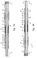
- a exemplary tractor 36 may include a forward anchor 60, an aft anchor 70, a forward thruster 80 and an aft thruster 100, all disposed on a mandrel or center tube 50. These components are energized using high pressure drilling fluid that is directed through tractor 36 by valve circuitry (not shown) and associated piping (not shown). The valve circuitry and associated piping will be referred to generally as valve circuitry hereinafter. Valve circuitry can be programmed to cause tractor 36 to deliver a thrust force to bit 30 and/or propel BHA 20 through well bore 22 (Fig. 2).
- Tube 50 transmits the thrust generated by forward and aft thrusters 80, 100 to bit 30.
- Tube 50 includes a medial portion 52 and first and second end portions 56, 58 and with a flowbore 54 extending therethrough.
- First and second end portions 56, 58 include connection interfaces for adjacent components in the bottom hole assembly 20.
- first end portion 56 may link tractor 36 with mud motor 34.
- Second end portion 58 may link tractor 36 with auxiliary equipment 38.
- Flowbore 54 provides a channel for conveying drilling fluid through tractor 36 to bit 30.
- Tube medial portion 52 telescopically reciprocates within tractor 36 as forward and aft thrusters 80, 100 alternately deliver their respective thrust forces to tube 50 in a manner described below.
- Forward anchor 60 holds forward thruster assembly 80 stationary relative to borehole wall 26 while forward thruster 80 urges tube 50 and aft thruster assembly 100 downhole towards well bottom 28 (i.e., direction "D").
- Forward anchor 60 includes borehole retention assemblies 62 and a housing 64.
- the tractor 36 valve circuitry directs high pressure drilling fluid into and out of actuation assemblies which are a part of borehole retention assemblies 62.
- Borehole retention assemblies 62 may include wedge members that extend radially or expandable bladder-like grippers.
- the introduction of drilling fluid causes borehole retention assemblies 62 to extend/inflate and engage borehole wall 26.
- Borehole retention assemblies 62 disengage borehole wall 26 when the valve circuitry discharges the drilling fluid into the annulus 25.
- aft anchor 70 engages borehole wall 26 while aft thruster 100 urges tube 50 downhole towards well bottom 28.
- aft anchor 70 includes borehole retention assemblies 72 and a housing 74.
- Forward thruster 80 generates a thrusting force that urges bit 30 downhole against the well bottom 28.
- Forward thruster 80 includes a cylinder member 82, a piston head 90, a closure member 92 and a valve assembly (not shown).
- Cylinder member 82 surrounds and freely slides along tube 50 and is a barrel-shaped member having a forward end 83, an interior chamber 84, and an aft end 85.
- Closure member 92 is received within forward end 83 of cylinder member 82 to seal interior chamber 84.
- Piston head 90 is fixed onto tube medial portion 52 and is positioned within chamber 84 to divide chamber 84 into a power section 86 and a reset section 88.
- Piston head 90 begins its stroke within chamber 84 next to cylinder aft end 85 and completes its stroke next to cylinder forward end 83.
- the valve circuitry initiates a stroke by injecting or "spurting" pre-determined amounts of drilling fluid into the power section 86 for a finely controlled rate of advancement.
- the valve assembly directs drilling fluid into reset section 88 to urge piston head 90 back to its original position.
- Aft thruster 100 generates the thrusting force that urges bit 30 downhole against the well bottom 28 in generally the same manner as forward thruster 80.
- Aft thruster 100 includes a cylinder 102, a piston head 110, a closure member 112, and associated valve assemblies (not shown). Cylinder member 102 surrounds and freely slides along tube 50. Cylinder member 102 is a barrel-shaped member having an forward end 103, an interior chamber 104, and an aft end 105. Closure member 112 is received by aft end 105 of cylinder member 102 to seal interior chamber 104.
- Piston head 110 mounts directly onto tube medial portion 52 and is positioned within chamber 104 to divide chamber 104 into a power section 106 and a reset section 108.
- Piston head 110 begins its stroke within chamber 104 next to cylinder aft end 105 and completes its stroke next to cylinder forward end 103.
- the valve assembly initiates a stroke by directing drilling fluid into the power section 106.
- the valve assembly directs drilling fluid into reset section 108 to urge piston head 110 back to its original position.
- forward thrust controller 130 controls the thrust generated by forward thruster 80.
- Forward thrust controller 130 includes a housing 132, a retainer 134 and at least one spring 136.
- Housing 132 includes first end 138, a back shoulder 140 forming an annular area 142 with tube 50, and a cavity 144.
- the cavity 144 is not sealed and although it initially preferably contains a high temperature grease, fluids such as annular drilling fluids may enter the cavity 144 during operation.
- Housing first end 138 is attached to forward anchor housing 64 (Fig. 3A) via a threaded connection or other suitable means.
- Retainer 134 transmits thrust between forward thruster 80 and spring 136.
- Retainer 134 includes a sleeve 146 and a collar 148 which are disposed around tube 50 and within housing cavity 144 in a piston-cylinder fashion.
- Sleeve 146 is generally a tubular member having a first end 143 and a second end 145 having collar 148.
- Sleeve 146 presents an outer surface 151 that is adapted to seat spring 136.
- First end 143 of sleeve 146 extends through the annular area 142 of back shoulder 140 and is attached to closure member 92 of forward thruster 80.
- Spring 136 on sleeve 146 is disposed between back shoulder 140 and collar 148.
- tube 50 When hydraulic pressure is applied on piston head 90 in power section 86, tube 50, which is attached to piston head 90, moves within thruster 80. Cylinder member 82, which is attached to forward anchor 60 via forward thrust controller 130, remains stationary as tube 50 moves within thruster 80. Should the bit 30 attached to tube 50 become stalled such as due to torque demand on the bit and mud motor, tube 50 will stop its forward movement. Also, tube 50 may stop its forward movement due to an excessive amount of "U" direction drag force from borehole wall 26 on tube 50. Because piston head 90 no longer can move, the hydraulic pressure will cause cylinder member 82 to move in a direction generally away from bit 30. As cylinder member 82 moves relative to forward anchor 60, collar 148 on sleeve 146 slides towards back shoulder 140 and compresses spring 136 between back shoulder 140 and collar 148.
- Spring 136 absorbs the energy associated with an undesired increase in the thrust developed by forward thruster 80.
- Spring 136 is disposed about sleeve 146 and is compressed against back shoulder 140 by collar 148.
- the capacity of spring 136 to absorb energy depends, in part, on the spring constant of the material forming the spring, the number of springs, and the diameter of the springs. It will be appreciated that springs, such as Belleville springs, are a relatively reliable and inexpensive biasing mechanism capable of absorbing bursts of increased thrust. Other methods utilizing coiled springs, compressible fluids, or other means may also be used in other circumstances.
- a resilient connection is established between forward borehole retention assembly 62 and cylinder member 82. Under normal operating conditions, this connection has a first state wherein a substantially solid connection is provided. Under overthrust conditions, this connection becomes resilient and allows cylinder member 82 to slide axially relative to forward borehole retention assembly 62 provided that the spring force of spring 136 is overcome.
- aft thrust controller 160 modulates the thrust generated by aft thruster 100. Similar to the construction of forward controller 130, aft thrust controller 160 includes a housing 162, a retainer 164, and at least one spring 166. Housing 162 includes a first end 167 forming a first shoulder 168, and a second end 169 forming a second shoulder 170 that forms an annular area 171 with tube 50, and a cavity 172. The cavity 172 is not sealed and although it initially preferably contains a high temperature grease, fluids such as annular drilling fluids may enter the cavity 172 during operation. Housing first end 167 is connected with aft anchor housing 74 (Fig.
- Retainer 164 transmits thrust to and from aft thruster 100 and spring 166.
- Retainer 164 includes a sleeve 174 and a collar 176 which are disposed around tube 50 and within housing cavity 172 in a piston-cylinder fashion.
- Sleeve 174 is generally a tubular member having a first end 178 and a second end 180 having collar 176.
- First end 178 of sleeve 174 extends through the annular area 171 and is connected to closure member 112 of aft thruster 100.
- tube 50 When hydraulic pressure is applied on piston head 110 in power section 106, tube 50, which is attached to piston head 110, moves within aft thruster 100. Cylinder member 102, which is attached to aft anchor 70 via aft thrust controller 160, remains stationary as tube 50 moves within aft thruster 100. Should the bit 30 attached to tube 50 become stalled such as due to encountering slow drilling formation or formation that requires higher torque to rotate the bit or an excessive amount of drag force, tube 50 will stop its forward movement. Because piston head 110 can no longer move, the hydraulic pressure will cause cylinder member 102 to move in a direction generally away from bit 30. As cylinder member 102 moves relative to aft anchor 70, collar 176 on sleeve 174 slides towards first shoulder 168 and compresses spring 166 between first shoulder 168 and collar 176.
- Spring 166 is formed in substantially the same manner as spring 136 of forward controller 130 and will not be discussed in further detail.
- a resilient connection is established between aft borehole retention assembly 72 and cylinder member 102. Under normal operating conditions, this connection has a first state wherein a substantially solid connection is provided. Under overthrust conditions, this connection becomes resilient and allows cylinder member 102 to slide axially relative to aft borehole retention assembly 72 provided that the spring force of spring 166 is overcome.
- valve circuitry sequentially energizes the components of tractor 36 to impart a thrust on tube 50.
- the sequence of this thrusting action has a first step wherein the forward anchor 60 and thruster 80 are energized and a second step wherein the aft anchor 70 and thruster 100 are energized.
- valve circuitry directs hydraulic fluid into forward anchor 60 to actuate borehole retention assembly 62. While forward anchor 60 engages borehole wall 26 (Fig. 2), valve circuitry injects hydraulic fluid into power section 86 of forward thruster 80. Under normal conditions, the hydraulic pressure in power section 86 works against piston head 90 to drive piston head 90 and connected tube 50 downhole in direction "D.” Once piston head 90 completes its stroke within chamber 84, the valve circuitry de-actuates forward borehole assembly 62 and directs drilling fluid into reset section 88 to reset piston head 90 within chamber 84.
- the second step begins with actuating aft anchor 70 causing borehole retention assembly 72 to engage borehole wall 26.
- the valve circuitry injects fluid into power section 106 of aft thruster 100.
- the hydraulic pressure in power section 106 drives piston head 110 and connected tube 50 downhole in direction "D."
- hydraulic fluid is directed into reset section 108 to reset piston head 110 within chamber 104 and the actuator assembly of borehole retention assembly 72 of aft anchor 70 to disengage from borehole wall 26. Thereafter, the operation repeats in substantially the same steps.
- controllers 130 and 160 are actuated when tube 50 encounters difficulty in moving downhole in direction "D." This can happen when attempting to drill through a particularly slow drilling formation or formation that causes an increase in the torque required to turn the drill bit 30 or when there is an excessive amount of drag force on tube 50. In either situation, the mud motor may unintentionally and nearly instantaneously raise the upstream differential pressure.
- forward anchor 60 engages borehole wall 26 (Fig. 2) while high pressure drilling fluid is directed into power section 86.
- the drilling fluid injected into power section 86 has a pressure higher than the desired operating pressure.
- the resilient connection between cylinder 82 and controller housing 132 enables the hydraulic pressure in power section 86 to urge cylinder 82 uphole in direction "U.”
- the axial motion of cylinder 82 and connected retainer 134 causes collar 148 to impart a compressive force on spring 136.
- spring 136 maintains a WOB on bit 30 until tube 50 can slide downhole in direction D. That is, while thruster 80 is energized, but not moving, spring 136 urges collar 148 downhole in direction D. Collar 148 transmits this thrust via sleeve 146 through closure member 92 to cylinder 82. This thrust is delivered through the generally non-compressed hydraulic fluid in chamber 86 to piston head 90 and ultimately through tube 50 to bit 30. Thus, the thrust delivered to bit 30 by tube 50 is that which is stored in spring 136, and not moving thruster 80.
- Aft controller 160 operates in substantially the same manner as forward controller 130.
- cylinder 102 In the event that tube 50 is prevented from movement downhole in direction "D" when hydraulic fluid is directed into power section 106, cylinder 102 is driven uphole in the "U” direction by the hydraulic pressure in power section 106. The movement of cylinder 102 also forces retainer 164 to move uphole in direction "U.” This movement by retainer 164 causes collar 176 to compress spring 166 against housing interior shoulder 168. As before, the spring 166 remains compressed until the thrust generated by the hydraulic pressure in power section 106 is reduced. The hydraulic pressure is reduced either due to bit drill-off where the rate the hole is drilled is faster than tractor rate of advancement or due to the end of the stroke.
- springs 136 and 166 incorporate a certain level of pre-compression that urges sleeves 146, 174 and thrusters 80, 100 downhole in direction D.
- This pre-compression is preferably enough to minimize any type of play or axial movement of retainers 134, 164 within their respective housings.
- This pre-compression may also provide a limited amount of compression of the spring from WOB during normal operating conditions.
- springs 136, 166 are sized to have the capacity to absorb as much thrust as can be generated in instances where an unusually slow drilling formation or formation that requires higher torque to rotate the bit is encountered by bit 30 or where there is an excessive amount of drag force on tube 50.
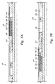
- thrust controllers 130, 160 constructed in accordance with a first alternative embodiment will now be described.
- the first alternative embodiment comprises the same elements and operates in the same manner as the preferred embodiment discussed above.
- the first alternative embodiment thrust controllers 130, 160 additionally comprise a dampener with orifices 510, 560 located in the collars 148, 176 of the forward and aft thrust controller retainers 134, 164, respectively. Cavities 144 and 172 are filled with oil or other fluid. In operation, increased loading across the thrust controllers 130, 160 allows movement between the thrusters 80, 100 and the borehole retention assemblies 62, 72.
- Thrusters 80, 100 and borehole retention assemblies 62, 72 thus move in accordance with the force stored in the springs 136, 166.
- the orifices 510, 560 restrict the movement of the borehole retention assemblies 62, 72 by requiring the fluid to pass through the orifices 510, 560.
- the orifices 510, 560 thereby restrict movement so that borehole retention assemblies 62, 72 will not slam against the thrusters 80, 100 whenever the borehole retention assemblies 62, 72 release their grip on the borehole.
- the orifice 510 has two positions, one maximum flow through orifice 510 and the other minimal flow therethrough. Flow through orifice 510 is maximized when spring 136 is being compressed to absorb energy and then is minimized when spring 136 is being de-compressed after borehole retention assembly 62 disengages borehole wall 26. This is done so that whenever the thruster 130 moves the tractor 36 down against the bit 30 during drilling, the movement of the thruster controller 130 and its ability to absorb load is not hampered by the orifice 510.
- the orifice 510 is biased toward the minimal flow position.
- the orifice 510 can be biased several ways and still remain within the spirit of the first alternative embodiment.
- One way is to have a spring biased piston 710 with a hole 720 through its center axis.
- a spring 730 loads the piston head 740 against a shoulder 750 that is the transition between diameters in a through hole 760 in the thrust controller collar 148.
- Fluid flow in the direction 770 that increases the thrust controller cavity 144 in volume causes the piston head 740 to seat more securely against the through hole inside shoulder 750. This allows flow only through the small hole 720 through its center axis.
- Fluid flow in the direction 780 that maximizes flow through orifice 510 pushes against the head of the piston 740 and biasing spring 730, moving the piston head 740 away from the shoulder 750, thereby increasing the flow area.
- Figure 6B Fluid flow in the direction 780 that maximizes flow through orifice 510 pushes against the head of the piston 740 and biasing
- thrust controllers 130, 160 constructed in accordance with a second alternative embodiment will now be described.
- the second alternative embodiment comprises the same elements and operates in the same manner as the preferred embodiment discussed above.
- the second alternative thrust controllers 130, 160 also comprise a dampener with orifices 510, 560 similar to those discussed above in the first alternative embodiment.
- the second alternative embodiment thrust controllers 130, 160 additionally comprise collar seals 610, 660 on the forward and aft retaining collars 148, 176, respectively.
- the collars 148, 176 are sealed so that movement between the forward and aft thrusters 80, 100 and the forward and aft borehole retention assemblies (not shown) forces fluid flow through the orifices 510, 560.
- the second alternative thrust controllers 130, 160 also comprise housing seals 615, 665 on the exterior portions 616, 666 of the forward and aft housings 64, 74.
- the cavities 144, 172 are sealed to the outside environment inside the borehole 26.
- the cavities 144, 172 are filled with a hydraulic fluid or high temperature grease, both fluids with low viscosity.
- Thrust controllers 130, 160 additionally comprise forward and aft biased volume compensator pistons 620, 670 located in enlarged diameter portions of the ends of forward and aft housings 64, 74 respectively. These pistons 620, 670 are biased by springs 625, 675 located in compensator cavities 630, 680 between the compensator pistons 620, 670 and the forward and aft compensator cavity shoulders 635, 685.
- the compensator cylinders 620, 670 are sealed with compensator seals 640, 645, 690, 695 to prevent fluid flow into the compensator cavities 630, 680.
- Retainer rings retain pistons 620, 670 in the enlarged diameter portions.
- the volume in cavities 144, 172 remains somewhat constant.
- movement of retaining collars 148, 176 changes the pressure in the volumes on either side of the collars 148, 176 that hinders movement of the retaining collars 148, 176.
- the fluid in controller cavities 144, 172 is not able to stabilize through the orifices 510, 550 quickly enough to balance the changes in volume and pressure on either side of the collars 148, 176.
- the compensator pistons 620, 670 adjust to account for the changes in volume on either side of the collars 148, 176. So as to not hinder movement of the compensator pistons 620, 670 with a similar pressure, the compensator cavities 630, 680 communicate with the environment outside the housings 64, 74 through ports 647, 697.
- the third alternative embodiment comprises the same elements and operates in the same manner as the preferred embodiment discussed above.
- the third alternative thrust controllers 130, 160 also comprise dampeners similar to those discussed above in the first or second alternative embodiments.
- the third alternative thrust controllers 130, 160 additionally comprise secondary biasing elements 810, 860.
- the first secondary biasing element 810 is located in the forward thrust controller cavity 144 between retainer collar 148 and the end 65 of housing 64.
- the second secondary biasing element 860 is located in the aft thrust controller cavity 172 between the collar 176 and the end 169 of housing 162.
- These secondary biasing elements 810, 860 are preferably springs that have limited movement, but can be other configurations without leaving the spirit of the third alternative embodiment.
- the forward and aft thrusters 80, 100 move in opposite directions than they would under overthrust conditions while moving the tube 50 into the borehole 22.
- the forward thruster 80 moves closer to the forward housing 64 and the aft thruster 100 moves further away from the aft housing 74. This movement prevents the tractor 36 from realizing the full length of the thruster stroke due to movement between the thrusters 80, 100 and the housings 64, 74 under load.
- the secondary biasing elements 810, 860 when the tractor 36 is moving in the reverse direction or coming out of the borehole 22, most of the length of the thruster strokes is realized in tractor 36 movement out of the borehole 22. This is because the secondary biasing elements 810, 860 reduce the total spring rate in upward direction but at minimal amount of movements so that the thruster strokes are not significantly reduced. The secondary biasing elements also reduce the total spring rate to protect the borehole retention assemblies (not shown) from high impact loads.
- the present invention may be adapted to nearly any arrangement of devices.
- the present invention has been described as applied to a tractor having two thrusters, the present teachings may be, as an example, advantageously applied to a BHA arrangement that includes only one thruster.
- the terms "U”, uphole, "D”, downhole, forward, and aft are terms merely to simplify the discussion of the various embodiments of the present invention. These terms, and other such similar terms, are not intended to denote any required movement or orientation with respect to the present invention.
Landscapes
- Engineering & Computer Science (AREA)
- Geology (AREA)
- Mining & Mineral Resources (AREA)
- Life Sciences & Earth Sciences (AREA)
- General Life Sciences & Earth Sciences (AREA)
- Fluid Mechanics (AREA)
- Environmental & Geological Engineering (AREA)
- Physics & Mathematics (AREA)
- Mechanical Engineering (AREA)
- Geochemistry & Mineralogy (AREA)
- Earth Drilling (AREA)
- Vehicle Body Suspensions (AREA)
- Fluid-Damping Devices (AREA)
- Vibration Dampers (AREA)
- Mechanical Treatment Of Semiconductor (AREA)
- Absorbent Articles And Supports Therefor (AREA)
- Actuator (AREA)
Applications Claiming Priority (3)
| Application Number | Priority Date | Filing Date | Title |
|---|---|---|---|
| US10/006,877 US6736223B2 (en) | 2001-12-05 | 2001-12-05 | Thrust control apparatus |
| US6877 | 2001-12-05 | ||
| PCT/US2002/034728 WO2003050375A2 (en) | 2001-12-05 | 2002-10-28 | Thrust control apparatus |
Publications (3)
| Publication Number | Publication Date |
|---|---|
| EP1485570A2 EP1485570A2 (en) | 2004-12-15 |
| EP1485570A4 EP1485570A4 (en) | 2005-11-23 |
| EP1485570B1 true EP1485570B1 (en) | 2007-10-10 |
Family
ID=21723052
Family Applications (1)
| Application Number | Title | Priority Date | Filing Date |
|---|---|---|---|
| EP02793852A Expired - Lifetime EP1485570B1 (en) | 2001-12-05 | 2002-10-28 | Thrust control apparatus |
Country Status (11)
| Country | Link |
|---|---|
| US (1) | US6736223B2 (es) |
| EP (1) | EP1485570B1 (es) |
| JP (1) | JP2005511933A (es) |
| CN (1) | CN1599833A (es) |
| AU (1) | AU2002359326B2 (es) |
| BR (1) | BR0214735A (es) |
| CA (1) | CA2469023C (es) |
| DE (1) | DE60222937T2 (es) |
| MX (1) | MXPA04005496A (es) |
| NO (1) | NO327434B1 (es) |
| WO (1) | WO2003050375A2 (es) |
Families Citing this family (14)
| Publication number | Priority date | Publication date | Assignee | Title |
|---|---|---|---|---|
| EP1703073A1 (en) * | 2005-03-17 | 2006-09-20 | Services Pétroliers Schlumberger | Methods and apparatus for moving equipment along a borehole |
| US7284606B2 (en) * | 2005-04-12 | 2007-10-23 | Baker Hughes Incorporated | Downhole position locating device with fluid metering feature |
| GB2469221B (en) * | 2008-01-03 | 2012-06-13 | Western Well Tool Inc | Anti-stall tool for downhole drilling assemblies |
| DK179473B1 (en) | 2009-10-30 | 2018-11-27 | Total E&P Danmark A/S | A device and a system and a method of moving in a tubular channel |
| DK177946B9 (da) | 2009-10-30 | 2015-04-20 | Maersk Oil Qatar As | Brøndindretning |
| DK178339B1 (en) | 2009-12-04 | 2015-12-21 | Maersk Oil Qatar As | An apparatus for sealing off a part of a wall in a section drilled into an earth formation, and a method for applying the apparatus |
| DK177547B1 (da) | 2011-03-04 | 2013-10-07 | Maersk Olie & Gas | Fremgangsmåde og system til brønd- og reservoir-management i udbygninger med åben zone såvel som fremgangsmåde og system til produktion af råolie |
| US8950513B2 (en) | 2012-10-03 | 2015-02-10 | Matthew Montgomery | Apparatus and methods for controlling drill string vibrations and applying a force to a drill bit |
| US10858895B2 (en) * | 2013-02-08 | 2020-12-08 | Qcd Technology Inc. | Axial, lateral and torsional force dampener |
| US20150090497A1 (en) * | 2013-10-01 | 2015-04-02 | Weatherford/Lamb, Inc. | Directional Drilling Using Variable Bit Speed, Thrust, and Active Deflection |
| EP3066288A4 (en) | 2014-01-21 | 2017-09-20 | Halliburton Energy Services, Inc. | Variable valve axial oscillation tool |
| US9663992B2 (en) * | 2014-08-26 | 2017-05-30 | Baker Hughes Incorporated | Downhole motor for extended reach applications |
| CN105937373B (zh) * | 2016-05-26 | 2018-07-03 | 中国石油集团渤海钻探工程有限公司 | 止点定位指示型减震推力器 |
| GB2593357B (en) | 2018-11-13 | 2023-04-05 | Rubicon Oilfield Int Inc | Three axis vibrating device |
Family Cites Families (26)
| Publication number | Priority date | Publication date | Assignee | Title |
|---|---|---|---|---|
| US2087677A (en) * | 1933-09-23 | 1937-07-20 | Seifer Theo | Boring motor |
| US2570577A (en) | 1947-06-13 | 1951-10-09 | Kenneth J Manion | Vibration absorber |
| US3099918A (en) | 1961-08-09 | 1963-08-06 | Drilco Oil Tools Inc | Resilient rotary drive fluid conduit |
| US3033011A (en) | 1960-08-31 | 1962-05-08 | Drilco Oil Tools Inc | Resilient rotary drive fluid conduit connection |
| US3180437A (en) | 1961-05-22 | 1965-04-27 | Jersey Prod Res Co | Force applicator for drill bit |
| US3122902A (en) | 1961-08-28 | 1964-03-03 | Drilprodco Inc | Drilling shock absorber |
| US3254508A (en) | 1963-09-18 | 1966-06-07 | Drilco Oil Tools Inc | Resilient unit for drill strings |
| US3230740A (en) | 1963-10-16 | 1966-01-25 | Fred K Fox | Drill string shock absorber and vibration dampener |
| US3301009A (en) | 1965-02-02 | 1967-01-31 | Rotary shock absorbing sub unit | |
| US3339380A (en) | 1965-09-16 | 1967-09-05 | Fred K Fox | Shock absorber |
| US3447340A (en) | 1967-05-29 | 1969-06-03 | Smith International | Resilient unit for drill strings |
| CH557753A (it) * | 1973-01-31 | 1975-01-15 | Alba Sa | Pennarello con punte multiple. |
| US3896886A (en) * | 1973-08-10 | 1975-07-29 | Bakerdrill Inc | Bore hole hammer drill |
| US3871193A (en) | 1973-12-12 | 1975-03-18 | Dresser Ind | Spring load system for drill string shock absorbers |
| US4207756A (en) * | 1977-10-21 | 1980-06-17 | Well Control, Inc. | Tension shock absorber device |
| US4162619A (en) | 1978-02-08 | 1979-07-31 | Maurer Engineering, Inc. | Drill string shock sub |
| US4194582A (en) | 1978-06-28 | 1980-03-25 | Christensen, Inc. | Double acting shock absorbers for drill strings |
| US4254837A (en) | 1979-04-12 | 1981-03-10 | Mustang Tripsaver Inc. | Technique for damping oscillations in a drill string |
| US4434863A (en) | 1979-05-14 | 1984-03-06 | Smith International, Inc. | Drill string splined resilient tubular telescopic joint for balanced load drilling of deep holes |
| US4466496A (en) | 1979-07-16 | 1984-08-21 | Mustang Trip Saver, Inc. | Technique for damping oscillations in a drill string |
| US4615401A (en) * | 1984-06-26 | 1986-10-07 | Smith International | Automatic hydraulic thruster |
| DE69016240T3 (de) | 1989-04-06 | 1999-03-11 | Sumitomo Electric Industries, Ltd., Osaka | Diamant für Abrichtungsvorrichtung |
| US6003606A (en) | 1995-08-22 | 1999-12-21 | Western Well Tool, Inc. | Puller-thruster downhole tool |
| BR9610373A (pt) * | 1995-08-22 | 1999-12-21 | Western Well Toll Inc | Ferramenta de furo de tração-empuxo |
| US5662180A (en) * | 1995-10-17 | 1997-09-02 | Dresser-Rand Company | Percussion drill assembly |
| US6241031B1 (en) * | 1998-12-18 | 2001-06-05 | Western Well Tool, Inc. | Electro-hydraulically controlled tractor |
-
2001
- 2001-12-05 US US10/006,877 patent/US6736223B2/en not_active Expired - Lifetime
-
2002
- 2002-10-28 MX MXPA04005496A patent/MXPA04005496A/es active IP Right Grant
- 2002-10-28 WO PCT/US2002/034728 patent/WO2003050375A2/en active IP Right Grant
- 2002-10-28 CN CN02824376.5A patent/CN1599833A/zh active Pending
- 2002-10-28 EP EP02793852A patent/EP1485570B1/en not_active Expired - Lifetime
- 2002-10-28 AU AU2002359326A patent/AU2002359326B2/en not_active Ceased
- 2002-10-28 BR BR0214735-1A patent/BR0214735A/pt not_active Application Discontinuation
- 2002-10-28 CA CA002469023A patent/CA2469023C/en not_active Expired - Fee Related
- 2002-10-28 DE DE60222937T patent/DE60222937T2/de not_active Expired - Fee Related
- 2002-10-28 JP JP2003551386A patent/JP2005511933A/ja active Pending
-
2004
- 2004-07-02 NO NO20042819A patent/NO327434B1/no not_active IP Right Cessation
Also Published As
| Publication number | Publication date |
|---|---|
| DE60222937T2 (de) | 2008-07-24 |
| CN1599833A (zh) | 2005-03-23 |
| WO2003050375A3 (en) | 2004-03-18 |
| NO327434B1 (no) | 2009-06-29 |
| MXPA04005496A (es) | 2005-03-23 |
| US20030102164A1 (en) | 2003-06-05 |
| JP2005511933A (ja) | 2005-04-28 |
| NO20042819L (no) | 2004-09-03 |
| AU2002359326B2 (en) | 2007-02-15 |
| US6736223B2 (en) | 2004-05-18 |
| WO2003050375A2 (en) | 2003-06-19 |
| BR0214735A (pt) | 2005-12-20 |
| EP1485570A2 (en) | 2004-12-15 |
| AU2002359326A1 (en) | 2003-06-23 |
| CA2469023C (en) | 2009-01-27 |
| CA2469023A1 (en) | 2003-06-19 |
| EP1485570A4 (en) | 2005-11-23 |
| DE60222937D1 (de) | 2007-11-22 |
Similar Documents
| Publication | Publication Date | Title |
|---|---|---|
| EP1485570B1 (en) | Thrust control apparatus | |
| US7766088B2 (en) | System and method for actuating wellbore tools | |
| CA2449506A1 (en) | Downhole tool | |
| US4632193A (en) | In-hole motor with bit clutch and circulation sub | |
| CA2284516C (en) | Rotary and longitudinal shock absorber for drilling | |
| EA000788B1 (ru) | Расположенная в скважине муфта с каналами для потока | |
| US20020032126A1 (en) | Borehole retention device | |
| CA2203736C (en) | Guided drilling system with shock absorber | |
| US10787875B2 (en) | Reaction valve drilling jar system | |
| AU2002242652A1 (en) | Device for anchoring a drill string in a borehole | |
| WO2002055834A1 (en) | Device for anchoring a drill string in a borehole | |
| EP1534925A1 (en) | Combined casing expansion / casing while drilling method and apparatus | |
| US4299296A (en) | In-hole motor drill with bit clutch | |
| US5964307A (en) | Shock tool for use in directional drilling | |
| US12049823B2 (en) | Drilling apparatus and method for use with rotating drill pipe | |
| US20230151706A1 (en) | Downhole Vibration Tool | |
| US20130186689A1 (en) | Downhole tool with external housing torque transfer |
Legal Events
| Date | Code | Title | Description |
|---|---|---|---|
| PUAI | Public reference made under article 153(3) epc to a published international application that has entered the european phase |
Free format text: ORIGINAL CODE: 0009012 |
|
| 17P | Request for examination filed |
Effective date: 20040702 |
|
| AK | Designated contracting states |
Kind code of ref document: A2 Designated state(s): AT BE BG CH CY CZ DE DK EE ES FI FR GB GR IE IT LI LU MC NL PT SE SK TR |
|
| AX | Request for extension of the european patent |
Extension state: AL LT LV MK RO SI |
|
| A4 | Supplementary search report drawn up and despatched |
Effective date: 20051010 |
|
| 17Q | First examination report despatched |
Effective date: 20060628 |
|
| GRAP | Despatch of communication of intention to grant a patent |
Free format text: ORIGINAL CODE: EPIDOSNIGR1 |
|
| GRAS | Grant fee paid |
Free format text: ORIGINAL CODE: EPIDOSNIGR3 |
|
| GRAA | (expected) grant |
Free format text: ORIGINAL CODE: 0009210 |
|
| AK | Designated contracting states |
Kind code of ref document: B1 Designated state(s): DE DK FR GB IT NL |
|
| REG | Reference to a national code |
Ref country code: GB Ref legal event code: FG4D |
|
| REF | Corresponds to: |
Ref document number: 60222937 Country of ref document: DE Date of ref document: 20071122 Kind code of ref document: P |
|
| PGFP | Annual fee paid to national office [announced via postgrant information from national office to epo] |
Ref country code: DK Payment date: 20071109 Year of fee payment: 6 Ref country code: NL Payment date: 20071109 Year of fee payment: 6 |
|
| PGFP | Annual fee paid to national office [announced via postgrant information from national office to epo] |
Ref country code: IT Payment date: 20071121 Year of fee payment: 6 |
|
| ET | Fr: translation filed | ||
| PG25 | Lapsed in a contracting state [announced via postgrant information from national office to epo] |
Ref country code: DK Free format text: LAPSE BECAUSE OF NON-PAYMENT OF DUE FEES Effective date: 20071010 |
|
| PLBE | No opposition filed within time limit |
Free format text: ORIGINAL CODE: 0009261 |
|
| STAA | Information on the status of an ep patent application or granted ep patent |
Free format text: STATUS: NO OPPOSITION FILED WITHIN TIME LIMIT |
|
| 26N | No opposition filed |
Effective date: 20080711 |
|
| PGFP | Annual fee paid to national office [announced via postgrant information from national office to epo] |
Ref country code: GB Payment date: 20080915 Year of fee payment: 7 |
|
| PGFP | Annual fee paid to national office [announced via postgrant information from national office to epo] |
Ref country code: DE Payment date: 20081031 Year of fee payment: 7 |
|
| PGFP | Annual fee paid to national office [announced via postgrant information from national office to epo] |
Ref country code: FR Payment date: 20081006 Year of fee payment: 7 |
|
| NLV4 | Nl: lapsed or anulled due to non-payment of the annual fee |
Effective date: 20090501 |
|
| PG25 | Lapsed in a contracting state [announced via postgrant information from national office to epo] |
Ref country code: NL Free format text: LAPSE BECAUSE OF NON-PAYMENT OF DUE FEES Effective date: 20090501 |
|
| PG25 | Lapsed in a contracting state [announced via postgrant information from national office to epo] |
Ref country code: IT Free format text: LAPSE BECAUSE OF NON-PAYMENT OF DUE FEES Effective date: 20081028 |
|
| REG | Reference to a national code |
Ref country code: FR Ref legal event code: ST Effective date: 20100630 |
|
| PG25 | Lapsed in a contracting state [announced via postgrant information from national office to epo] |
Ref country code: FR Free format text: LAPSE BECAUSE OF NON-PAYMENT OF DUE FEES Effective date: 20091102 Ref country code: DE Free format text: LAPSE BECAUSE OF NON-PAYMENT OF DUE FEES Effective date: 20100501 |
|
| PG25 | Lapsed in a contracting state [announced via postgrant information from national office to epo] |
Ref country code: GB Free format text: LAPSE BECAUSE OF NON-PAYMENT OF DUE FEES Effective date: 20091028 |