EP1485180B1 - Fluidfilteranordnung - Google Patents
Fluidfilteranordnung Download PDFInfo
- Publication number
- EP1485180B1 EP1485180B1 EP02757192A EP02757192A EP1485180B1 EP 1485180 B1 EP1485180 B1 EP 1485180B1 EP 02757192 A EP02757192 A EP 02757192A EP 02757192 A EP02757192 A EP 02757192A EP 1485180 B1 EP1485180 B1 EP 1485180B1
- Authority
- EP
- European Patent Office
- Prior art keywords
- filter
- assembly
- grommet
- diameter
- elongated
- Prior art date
- Legal status (The legal status is an assumption and is not a legal conclusion. Google has not performed a legal analysis and makes no representation as to the accuracy of the status listed.)
- Expired - Lifetime
Links
- 239000012530 fluid Substances 0.000 title claims abstract description 57
- 238000007789 sealing Methods 0.000 claims description 12
- 239000011521 glass Substances 0.000 claims description 3
- 239000007788 liquid Substances 0.000 abstract description 7
- 239000000446 fuel Substances 0.000 description 23
- 239000002828 fuel tank Substances 0.000 description 7
- 239000000463 material Substances 0.000 description 5
- 229920001944 Plastisol Polymers 0.000 description 2
- 230000015556 catabolic process Effects 0.000 description 2
- 238000007599 discharging Methods 0.000 description 2
- 239000004999 plastisol Substances 0.000 description 2
- 229920002449 FKM Polymers 0.000 description 1
- 239000000853 adhesive Substances 0.000 description 1
- 230000001070 adhesive effect Effects 0.000 description 1
- 230000000712 assembly Effects 0.000 description 1
- 238000000429 assembly Methods 0.000 description 1
- 239000000356 contaminant Substances 0.000 description 1
- 230000037431 insertion Effects 0.000 description 1
- 238000003780 insertion Methods 0.000 description 1
- 230000013011 mating Effects 0.000 description 1
- 239000003566 sealing material Substances 0.000 description 1
- 239000007787 solid Substances 0.000 description 1
Images



Classifications
-
- B—PERFORMING OPERATIONS; TRANSPORTING
- B01—PHYSICAL OR CHEMICAL PROCESSES OR APPARATUS IN GENERAL
- B01D—SEPARATION
- B01D27/00—Cartridge filters of the throw-away type
- B01D27/08—Construction of the casing
-
- B—PERFORMING OPERATIONS; TRANSPORTING
- B01—PHYSICAL OR CHEMICAL PROCESSES OR APPARATUS IN GENERAL
- B01D—SEPARATION
- B01D2201/00—Details relating to filtering apparatus
- B01D2201/30—Filter housing constructions
- B01D2201/301—Details of removable closures, lids, caps, filter heads
- B01D2201/304—Seals or gaskets
-
- B—PERFORMING OPERATIONS; TRANSPORTING
- B01—PHYSICAL OR CHEMICAL PROCESSES OR APPARATUS IN GENERAL
- B01D—SEPARATION
- B01D2201/00—Details relating to filtering apparatus
- B01D2201/34—Seals or gaskets for filtering elements
Definitions
- the present disclosure relates to fluid filters, and in particular to filters for liquid fuel. More particularly, the present disclosure relates to fluid filter assemblies including sealed outlets for discharging filtered fuel to a destination outside the fluid filter assembly.
- Fluid filters are used onboard vehicles and in other apparatus containing fluid transport systems to remove unwanted solids or other contaminants from the fluid.
- Oil filters and fuel filters are provided to clean oil and fuel used in vehicle engines. Filter seals are used to minimize unwanted leakage of fluids such as oil and fuel from a fluid filter.
- a fluid filter assembly in accordance with the present disclosure includes a filter housing, a filter element, and a fluid discharge system for discharging liquid fuel from a filtered-fluid region formed in the filter element to destinations outside of the filter housing.
- the fluid discharge system includes an outlet conduit extending from the filtered-fluid region through an aperture formed in the filter housing and an inlet conduit carrying liquid fuel into the filter housing for delivery to the filter element.
- the fluid discharge system further includes an elongated grommet mounted to extend around the outlet conduit to lie in sealing engagement with the filter element and the filter housing.
- the grommet is arranged inside the filter housing to block unfiltered liquid fuel discharged into the filter housing through the inlet conduit from mixing with filtered fuel in the filtered-fluid region of the filter element.
- an inner end of the elongated grommet is located to close and seal a gap between the filter element and the outlet conduit to block unwanted leakage of fluid from the filtered-fluid region into other spaces in the filter housing.
- An outer end of the elongated grommet is located to engage the filter housing.
- the elongated grommet has a necked-down mid-portion providing the elongated grommet with an hour-glass shape.
- the fluid filter assembly is configured to filter fuel that is delivered from a fuel tank to an engine and the outlet conduit is adapted to return some of the filtered fuel to the fuel tank.
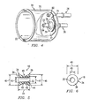
- An elongated grommet 10 is provided as shown, for example, in Figs. 1-6 for use in a fluid filter assembly 12 to manage flow of fluid in the assembly 12 so as to avoid unwanted mixing of unfiltered fluid with already filtered fluid inside fluid filter assembly 12.
- Another elongated grommet 110 is shown in Figs. 9-12 and yet another grommet 210 is shown in Fig. 13 .
- These grommets are configured to maintain sealing relationships with adjacent filter assembly components even if one or more of those components is mounted in a misaligned position in fluid filter assembly 12.
- Fluid filter assembly 12 is used in an illustrative embodiment to filter liquid fuel that has been drawn from a fuel tank 14 by a fuel pump 16 before the fuel is delivered to an engine 18.
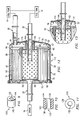
- Fluid filter assembly 12 includes a filter element 20 positioned to lie in a filter chamber 22 formed in a filter housing 24, an inlet conduit 26 adapted to receive fuel from fuel tank 14, a first outlet conduit 28 adapted to discharge fuel filtered by filter element 20 to engine 18, and a second outlet conduit 30 adapted to discharge some of the fuel filtered by filter element 20 to fuel tank 14.
- Each conduit 26, 28, and 30 is coupled to filter housing 24 to communicate with filter chamber 22 formed in filter housing 24 as shown, for example, in Fig. 2 .
- grommet 10 is formed to include a passageway 32 sized to receive a central portion 33 of second outlet conduit 30 therein. Although in the illustrated embodiment, a fluid-tight seal is established between grommet 10 and central portion 33, it is within the scope of this disclosure to fit grommet 10 in a "loose" manner on central portion 33 without establishing a fluid-tight seal therebetween.
- Grommet 10 is a monolithic element made, for example, of VITON (V2174) material.
- grommet 10 comprises first and second frustoconical members 34, 36 arranged to lie in "end-to-end" relation as shown, for example, in Figs. 1 , 3 , and 5 to provide grommet 10 with an "hour-glass" shape.
- First frustoconical member 34 has a large-diameter base 38 having a diameter 40 and a smaller-diameter top 42.
- Second frustoconical member 36 has a large-diameter base 44 having a diameter 46 about equal to diameter 40 and a smaller-diameter top 48 appended to smaller-diameter top of first frustoconical member 34 to form a "necked-down" section 49 of grommet 10.
- the diameters 40, 46 of large-diameter bases 3 8, 44 are about equal to the length 11 of grommet 10.
- Each smaller-diameter top 42, 48 has a diameter 47 that is about 60% of diameter 40 of large-diameter base 38.
- Passageway 32 has an internal diameter 45 that is about one-half of diameter 40 of large-diameter base 38.
- Filter element 20 includes a filter media 50 providing interior and exterior portions 52, 54 and an end cap 56 coupled to one end 58 of filter media 50 as shown, for example, in Figs. 2 and 3 .
- Interior portion 52 is configured to define a filtered-fluid region 60 located in filter element 20 to receive fluid in filter element 20 that has passed through filter media 50 from exterior portion 52 to interior portion 54. It is within the scope of this disclosure to use any suitable filter media.
- End cap 56 includes an interior edge 61 formed to define a conduit-receiving aperture 62 arranged to receive second outlet conduit 30 therein to locate an inlet end 64 of second outlet conduit 30 in filtered-fluid region 60 as shown, for example, in Fig. 2 .
- End cap 56 includes inner disk 65, annular inner wall 66, outer disk 67, and annular outer wall 68 as shown, for example, in Fig. 3 .
- PLASTISOL adhesive 69 or other suitable material is used to adhere end 58 of filter media 50 in a sealed fixed position to end cap 56.
- Filter housing 24 includes a cup 70, an end plate 72, and an internal conduit support hat 74 as shown, for example, in Figs. 2-4 .
- Cup 70 includes a side wall 75 arranged to surround filter element 20 to define an annular space 76 therebetween and a top wall 77 coupled to inlet conduit 26 and second outlet conduit 30 as shown, for example, in Fig. 2 .
- End cap 56 is arranged to lie in spaced-apart relation to top wall 77 to define a space 73 receiving grommet 10 and internal conduit support hat 74 therein.
- Internal conduit support hat 74 includes a flared sleeve 78 adapted to receive and engage central portion 33 of second outlet conduit 30 and an annular base 79 appended to flared sleeve 78 and coupled to top wall 77 of housing cup 70 as suggested, for example, in Figs. 2-4 .
- Base end 59 of filter media 50 is adhered to end plate 72 using PLASTISOL material 69 or other suitable material to mount filter element 20 in a sealed fixed position on end plate 72 as shown, for example, in Figs. 2 and 3 .
- End plate 72 is coupled to side wall 75 of housing cup 70 as suggested in Figs. 2 and 3 to position filter element 20 in a fixed position in filter chamber 22 formed in filter housing 24.
- end plate 72 and first outlet conduit 28 cooperate to form a monolithic base for housing cup 70.
- Inlet conduit 26 has an inner end 80 sized to carry a washer 81 and extend through an aperture 82 formed in top wall 77 of housing cup 70 as suggested, for example, in Figs. 2-4 .
- second outlet conduit 30 is sized to carry a washer 83 and extend through an aperture 84 formed in top wall 77 of housing cup 70.
- Each conduit is brazed to its washer and each washer is brazed to top wall 77 to mount the conduits in place on housing cup 70 as shown, for example, in Figs. 2 and 4 .
- Internal conduit support hat 74 is also brazed to an interior surface of top wall 77.
- Grommet 10 and second outlet conduit 30 cooperate to provide means for conducting fuel from filtered-fluid region 60 in filter element 20 through aperture 84 formed in filter housing 24 toward fuel tank 14.
- Grommet 10 is positioned to lie in filter chamber 22 in a space 73 between filter element 20 and filter housing 24.
- Grommet 10 is mounted on central portion 33 of second outlet conduit 30 to lie in sealing engagement with filter element 20 and filter housing 24, to block any unwanted fuel leakage of unfiltered fuel discharged into space 73 by inlet conduit 26 from the portion of space 73 around grommet 10 into filtered-fluid region 60 in filter element 20 through the opening 62 formed in filter element 20.
- an inner end 38 of grommet 10 to lie in sealing engagement with inner disk 65 of end cap 56 of filter element 20 and an outer end 44 of grommet 10 to lie in sealing engagement with an interior surface of top wall 77 of filter housing 24 as shown, for example, in Fig. 2 .
- Inner end 38 of grommet 10 engages end cap 56 to close any gap extant between interior edge 61 of end cap 56 and central portion 33 of second outlet conduit 30.
- Outer end 44 of grommet 10 sealingly engages internal conduit support hat 74.
- Grommet 10 is made of a pliable sealing material so as to permit relative movement between first and second frustoconical portions 34, 36 when certain components of fluid filter assembly 12 are misaligned with respect to filter housing 24. As shown, for example, in Fig. 7 , grommet 10 deforms to maintain sealing engagement with end cap 56 and filter housing 24 in the event that filter element 20 is misaligned within filter housing 24 (e.g. canted relative to axis 85 to cause a plane 86 defined by outer disk 67 to lie at an angle 87 relative to vertical plane 88). As shown, for example, in Fig.
- grommet 10 deforms to maintain sealing engagement with end cap 56 and filter housing 24 in the event that second outlet conduit 30 is misaligned relative to filter housing 24 (e.g. canted at an angle 89 relative to axis 85).
- grommet 10 comprises two mating frustoconical portions 34, 36 in the embodiment shown in Figs. 1-8 , it is within the scope of this disclosure to vary the shape of portions 34, 36 somewhat while maintaining a necked-down section 49.
- a grommet 110 is mounted on central portion 33 of second outlet conduit 30 instead of grommet 10.
- Grommet 110 is made of a material similar to grommet 10 and is formed to include passageway 132, inner end 138, outer end 144, and cylindrical side wall 145.
- a grommet 210 is mounted loosely on central portion 33 of second outlet conduit 30 without establishing a fluid-tight seal therebetween. Nevertheless, in each of the embodiments shown in Figs.
- the grommets 110,210 are arranged to have an inner end positioned to lie in sealing engagement with filter element 20 and an outer end positioned to lie in sealing engagement with filter housing 24 to establish a seal therebetween so that unfiltered fluid in filter chamber 22 does not bypass filter element 20 by leaking into filtered-fluid region 60 in filter element 20.
Landscapes
- Chemical & Material Sciences (AREA)
- Chemical Kinetics & Catalysis (AREA)
- Lubrication Details And Ventilation Of Internal Combustion Engines (AREA)
- Filtering Of Dispersed Particles In Gases (AREA)
- Filtration Of Liquid (AREA)
- Infusion, Injection, And Reservoir Apparatuses (AREA)
- Separation By Low-Temperature Treatments (AREA)
Claims (17)
- Fluidfilterbaugruppe (12, 112) miteinem Filtergehäuse (24), das so ausgebildet ist, dass es eine Filterkammer (22) aufweist,einem Filterelement (20), das so positioniert ist, dass es in der Filterkammer liegt,einer langgestreckten Durchführungsdichtung (10), die in der Filterkammer liegt und ein inneres Ende aufweist, das so angeordnet ist, dass es mit dem Filterelement in abdichtendem Eingriff liegt, sowie ein äußeres Ende, das so angeordnet ist, dass es mit dem Filtergehäuse in abdichtendem Eingriff liegt, undeiner Auslassleitung, die sich von einem in dem Filterelement ausgebildeten Bereich für gefiltertes Fluid durch eine in dem Filterelement ausgebildete Öffnung, einen in der langgestreckten Durchführungsdichtung ausgebildeten Durchgang (32, 132) und eine in dem Filtergehäuse ausgebildete Öffnung zu einer Zielstelle außerhalb des Filtergehäuses erstreckt, um Fluid von dem Bereich für gefiltertes Fluid zu der Zielstelle außerhalb des Filtergehäuses zu leiten, wobei das Filtergehäuse eine innere Abdeckung (74) zum Halten der Leitung aufweist, die in der Filterkammer angeordnet und so ausgebildet ist, dass sie eine Öffnung aufweist, durch die sich die Auslassleitung erstreckt, wobei sich die innere Abdeckung zum Halten der Leitung in den in der langgestreckten Durchführungsdichtung ausgebildeten Durchgang erstreckt, dadurch gekennzeichnet, dass die langgestreckte Durchführungsdichtung ein monolithisches Element mit einem ersten kegelstumpfartigen Teil (34) ist, das das innere Ende definiert, und mit einem zweiten kegelstumpfartigen Teil (36), das das äußere Ende definiert, und das erste kegelstumpfartige Teil (34) eine Basis mit großen Durchmesser und einen oberen Abschnitt mit kleinem Durchmesser aufweist und das zweite kegelstumpfartige Teil (36) eine Basis mit großem Durchmesser und einen oberen Abschnitt mit kleinem Durchmesser aufweist, der an dem oberen Abschnitt mit kleinem Durchmesser des ersten kegelstumpfartigen Teils befestigt ist, so dass ein eingeschnürter Abschnitt der langgestreckten Durchführungsdichtung (10) gebildet ist und die langgestreckte Durchführungsdichtung eine Sanduhrform erhält.
- Baugruppe nach Anspruch 1, bei der das Filterelement ein Filtermedium (50) aufweist, das so ausgebildet ist, dass es den Bereich für gefiltertes Fluid und eine Endkappe (56) umfasst, die mit einem Ende des Filtermediums verbunden ist, wobei die Basis mit großem Durchmesser des ersten kegelstumpfartigen Teils so angeordnet ist, dass sie in die Endkappe eingreift, und die Basis mit großem Durchmesser des zweiten kegelstumpfartigen Teils so angeordnet ist, dass sie an der inneren Abdeckung zum Halten der Leitung angreift.
- Baugruppe nach Anspruch 2, bei der die Endkappe einen Innenrand (61) aufweist, der so ausgebildet ist, dass er eine Öffnung definiert, durch die sich die Auslassleitung in den Bereich für gefiltertes Fluid erstreckt, und die Basis mit großem Durchmesser des ersten kegelstumpfartigen Teils jeglichen Spalt schließt, der zwischen dem Innenrand der Endkappe und der Auslassleitung vorhanden ist.
- Baugruppe nach Anspruch 1, bei der die langgestreckte Durchführungsdichtung (10) eine vorbestimmte Länge hat und der Durchmesser jeder Basis mit großem Durchmesser etwa der vorbestimmten Länge der langgestreckten Durchführungsdichtung entspricht.
- Baugruppe nach Anspruch 1, bei der der in der langgestreckten Durchführungsdichtung ausgebildete Durchgang (32, 132) einen Innendurchmesser hat, der etwa dem halben Durchmesser der Basis mit großem Durchmesser des ersten kegelstumpfartigen Teils entspricht.
- Baugruppe nach Anspruch 1, bei der das innere Ende der langgestreckten Durchführungsdichtung (10) einen vorbestimmten Durchmesser hat, die langgestreckte Durchführungsdichtung ferner einen eingeschnürten Abschnitt aufweist, der so angeordnet ist, dass er zwischen dem inneren Ende und dem äußeren Ende liegt, und der eingeschnürte Abschnitt einen Außendurchmesser hat, der etwa 60% des vorbestimmten Durchmessers des inneren Endes der langgestreckten Durchführungsdichtung entspricht.
- Baugruppe nach Anspruch 1, bei der die langgestreckte Durchführungsdichtung eine vorbestimmte Länge hat und das innere Ende einen Durchmesser hat, der etwa der vorbestimmten Länge entspricht.
- Baugruppe nach Anspruch 1, bei der das Filterelement ein Filtermedium (50) aufweist, das so ausgebildet ist, dass es den Bereich (60) für gefiltertes Fluid und eine Endkappe umfasst, die mit einem Ende des Filtermediums verbunden ist, und das innere Ende der Durchführungsdichtung so angeordnet ist, dass es in die Endkappe eingreift.
- Baugruppe nach Anspruch 8, bei der die Endkappe (56) einen Innenrand (61) aufweist, der so ausgebildet ist, dass er eine Öffnung definiert, durch die sich die Auslassleitung in den Bereich für gefiltertes Fluid erstreckt, und das innere Ende der Durchführungsdichtung jeglichen Spalt schließt, der zwischen dem Innenrand der Endkappe und der Auslassleitung vorhanden ist.
- Baugruppe nach Anspruch 8, bei der die Endkappe (56) eine in axiale Richtung gewandte Fläche aufweist und das innere Ende der Durchführungsdichtung eine in axialer Richtung gewandte Stirnfläche aufweist, die an der axial gerichteten Fläche der Endkappe angreift.
- Baugruppe nach Anspruch 1, bei der das äußere Ende der langgestreckten Durchführungsdichtung (10) so angeordnet ist, dass es mit der inneren Abdeckung (74) zum Halten der Leitung in abdichtendem Eingriff liegt.
- Baugruppe nach Anspruch 1, bei der die innere Abdeckung zum Halten der Leitung eine konisch erweiterte Hülse (78) aufweist, die so angeordnet ist, dass sie an dem äußeren Ende der langgestreckten Durchführungsdichtung angreift, um das äußere Ende zu verformen.
- Baugruppe nach Anspruch 1, bei der sich die innere Abdeckung zum Halten der Leitung bei ihrer Erstreckung axial nach innen in den in der langgestreckten Durchführungsdichtung ausgebildeten Durchgang (32, 132) radial nach innen verjüngt.
- Baugruppe nach Anspruch 1, bei der das Filtergehäuse eine Schale (70) mit einer Seitenwand (75) und einer mit der oberen Wand verbundenen oberen Wand (77) aufweist, wobei die Seitenwand so angeordnet ist, dass sie das Filterelement umgibt, die obere Wand so ausgebildet ist, dass sie die in dem Filtergehäuse ausgebildete Öffnung aufweist, und die innere Abdeckung zum Halten der Leitung so angeordnet ist, dass sie in der Filterkammer (22) zwischen der oberen Wand und der langgestreckten Durchführungsdichtung liegt.
- Baugruppe nach Anspruch 14, bei der die innere Abdeckung zum Halten der Leitung eine mit der oberen Wand verbundene ringförmige Basis (79) und eine konisch erweiterte Hülse aufweist, die sich von der ringförmigen Basis in den Durchgang erstreckt.
- Baugruppe nach Anspruch 15, bei der sich die konisch erweiterte Hülse (78) bei ihrer Erstreckung axial nach innen in den Durchgang, wo die konisch erweiterte Hülse an einem Ende der inneren Abdeckung zum Halten der Leitung endet, radial nach innen verjüngt.
- Baugruppe nach Anspruch 1, die ferner eine zweite Auslassleitung aufweist, die mit dem Filtergehäuse (24) verbunden und so angeordnet ist, dass sie Fluid von dem Bereich (60) für gefiltertes Fluid in dem Filterelement zu einer zweiten Zielstelle außerhalb des Filtergehäuses leitet.
Applications Claiming Priority (3)
| Application Number | Priority Date | Filing Date | Title |
|---|---|---|---|
| US10/084,964 US6595371B1 (en) | 2002-02-28 | 2002-02-28 | Fluid filter assembly |
| US84964 | 2002-02-28 | ||
| PCT/US2002/026216 WO2003074150A1 (en) | 2002-02-28 | 2002-08-19 | Fluid filter assembly |
Publications (3)
| Publication Number | Publication Date |
|---|---|
| EP1485180A1 EP1485180A1 (de) | 2004-12-15 |
| EP1485180A4 EP1485180A4 (de) | 2005-03-30 |
| EP1485180B1 true EP1485180B1 (de) | 2010-05-26 |
Family
ID=22188327
Family Applications (1)
| Application Number | Title | Priority Date | Filing Date |
|---|---|---|---|
| EP02757192A Expired - Lifetime EP1485180B1 (de) | 2002-02-28 | 2002-08-19 | Fluidfilteranordnung |
Country Status (11)
| Country | Link |
|---|---|
| US (1) | US6595371B1 (de) |
| EP (1) | EP1485180B1 (de) |
| JP (1) | JP3889401B2 (de) |
| AT (1) | ATE468899T1 (de) |
| AU (1) | AU2002323228B2 (de) |
| BR (1) | BR0213231A (de) |
| CA (1) | CA2463292C (de) |
| DE (1) | DE60236547D1 (de) |
| ES (1) | ES2347322T3 (de) |
| MX (1) | MXPA04006467A (de) |
| WO (1) | WO2003074150A1 (de) |
Families Citing this family (21)
| Publication number | Priority date | Publication date | Assignee | Title |
|---|---|---|---|---|
| US9233322B1 (en) | 2008-08-08 | 2016-01-12 | Kx Technologies Llc | Push filter with floating key lock |
| US11426685B2 (en) | 2008-08-08 | 2022-08-30 | Kx Technologies Llc | Push filter with floating key lock |
| US9901852B2 (en) | 2008-08-08 | 2018-02-27 | Kx Technologies Llc | Push filter with floating key lock |
| US9821253B2 (en) * | 2013-11-19 | 2017-11-21 | Motor Components, Llc | Axially compact fuel filter |
| US20170175692A1 (en) * | 2015-12-21 | 2017-06-22 | K&N Engineering, Inc. | Application specific fuel filter |
| KR101892047B1 (ko) * | 2018-02-13 | 2018-08-27 | 김용준 | 필터 하우징 |
| CN112334080B (zh) | 2018-06-13 | 2024-08-16 | 史赛克欧洲运营有限公司 | 骨屑收集装置和处理装置 |
| US11273397B2 (en) | 2018-09-13 | 2022-03-15 | Electrolux Home Products, Inc. | Filter base for electronic connection to mating filter housing assembly |
| WO2021050693A1 (en) * | 2019-09-13 | 2021-03-18 | Kx Technologies Llc | Filter base for electronic connection to mating filter housing assembly |
| USD948659S1 (en) | 2019-11-18 | 2022-04-12 | Electrolux Home Products, Inc. | Filter cartridge |
| USD946702S1 (en) | 2019-11-18 | 2022-03-22 | Electrolux Home Products, Inc. | Filter cartridge |
| USD946701S1 (en) | 2019-11-18 | 2022-03-22 | Electrolux Home Products, Inc. | Filter cartridge |
| USD946703S1 (en) | 2019-11-18 | 2022-03-22 | Electrolux Home Products, Inc. | Filter cartridge |
| USD946699S1 (en) | 2019-11-18 | 2022-03-22 | Electrolux Home Products, Inc. | Filter cartridge |
| USD969270S1 (en) | 2019-11-18 | 2022-11-08 | Electrolux Home Products, Inc. | Filter cartridge |
| USD948660S1 (en) | 2019-11-18 | 2022-04-12 | Electrolux Home Products, Inc. | Filter cartridge |
| US11413560B2 (en) | 2019-11-18 | 2022-08-16 | Electrolux Home Products, Inc. | Push filter with floating key lock |
| USD946700S1 (en) | 2019-11-18 | 2022-03-22 | Electrolux Home Products, Inc. | Filter cartridge |
| US12274629B2 (en) | 2019-12-18 | 2025-04-15 | Stryker European Operations Limited | Bone fragment collector and processor |
| EP3904700A1 (de) * | 2020-04-28 | 2021-11-03 | Hamilton Sundstrand Corporation | Filteranordnung für ein servoventil |
| US12564801B2 (en) * | 2021-03-18 | 2026-03-03 | Volvo Truck Corporation | Oil filter with two filtrate outlets and vehicle lubrication circuit |
Family Cites Families (11)
| Publication number | Priority date | Publication date | Assignee | Title |
|---|---|---|---|---|
| GB1589235A (en) * | 1977-07-04 | 1981-05-07 | Ucc International Ltd | Disposable filter canister and oil filter assembly which includes the canister |
| US4372847A (en) | 1980-06-23 | 1983-02-08 | Chicago Rawhide Manufacturing Company | Fuel filter assembly and cartridge |
| US4456529A (en) * | 1982-10-21 | 1984-06-26 | Applied Diesel Engineering, Inc. | Filter device for diesel engines |
| DE3635728A1 (de) * | 1986-10-21 | 1988-04-28 | Bosch Gmbh Robert | Fluessigkeitsfilter, insbesondere fuer kraftstoffe |
| DE4134367A1 (de) * | 1991-10-17 | 1993-04-22 | Bosch Gmbh Robert | Fluessigkeitsfilter |
| US5423984A (en) | 1993-04-13 | 1995-06-13 | Facet International, Inc. | Fluid filter |
| DE4430471A1 (de) * | 1994-08-27 | 1996-02-29 | Bosch Gmbh Robert | Flüssigkeitsfilter mit eingebautem Druckregler |
| DE19536084A1 (de) * | 1995-09-28 | 1997-04-03 | Bosch Gmbh Robert | Flüssigkeitsfilter mit eingebautem Druckregler |
| US5637215A (en) | 1995-10-18 | 1997-06-10 | Purolator Products Company | Fuel filter having improved communication with a contaminant container |
| DE19754243A1 (de) * | 1997-12-06 | 1999-06-10 | Bosch Gmbh Robert | Flüssigkeitsfilter mit eingebautem Druckregler |
| EP1008375A1 (de) * | 1998-12-11 | 2000-06-14 | Baldwin Filters, Inc. | Wegwerfbare Kraftstoffilterdeckelanordnung |
-
2002
- 2002-02-28 US US10/084,964 patent/US6595371B1/en not_active Expired - Lifetime
- 2002-08-19 AU AU2002323228A patent/AU2002323228B2/en not_active Expired - Fee Related
- 2002-08-19 AT AT02757192T patent/ATE468899T1/de not_active IP Right Cessation
- 2002-08-19 JP JP2003572658A patent/JP3889401B2/ja not_active Expired - Fee Related
- 2002-08-19 CA CA2463292A patent/CA2463292C/en not_active Expired - Fee Related
- 2002-08-19 ES ES02757192T patent/ES2347322T3/es not_active Expired - Lifetime
- 2002-08-19 BR BR0213231-1A patent/BR0213231A/pt not_active Application Discontinuation
- 2002-08-19 DE DE60236547T patent/DE60236547D1/de not_active Expired - Lifetime
- 2002-08-19 MX MXPA04006467A patent/MXPA04006467A/es active IP Right Grant
- 2002-08-19 WO PCT/US2002/026216 patent/WO2003074150A1/en not_active Ceased
- 2002-08-19 EP EP02757192A patent/EP1485180B1/de not_active Expired - Lifetime
Also Published As
| Publication number | Publication date |
|---|---|
| DE60236547D1 (de) | 2010-07-08 |
| CA2463292A1 (en) | 2003-09-12 |
| MXPA04006467A (es) | 2004-10-04 |
| ES2347322T3 (es) | 2010-10-28 |
| CA2463292C (en) | 2012-04-17 |
| ATE468899T1 (de) | 2010-06-15 |
| EP1485180A4 (de) | 2005-03-30 |
| JP3889401B2 (ja) | 2007-03-07 |
| JP2005518923A (ja) | 2005-06-30 |
| AU2002323228B2 (en) | 2008-05-29 |
| US6595371B1 (en) | 2003-07-22 |
| EP1485180A1 (de) | 2004-12-15 |
| AU2002323228A1 (en) | 2003-09-16 |
| BR0213231A (pt) | 2004-09-28 |
| WO2003074150A1 (en) | 2003-09-12 |
Similar Documents
| Publication | Publication Date | Title |
|---|---|---|
| US6595371B1 (en) | Fluid filter assembly | |
| CA2652904C (en) | Tri-flow filter element with venting | |
| CN105327577B (zh) | 用于分离流体的装置以及该装置的壳体、壳盖和连接件 | |
| CN105283659B (zh) | 空心过滤器元件、过滤器壳和过滤器 | |
| CN101991985B (zh) | 用于过滤流体的过滤器系统的密封装置 | |
| CN1119523C (zh) | 安装于燃料管内的单独滤清器 | |
| US8465643B2 (en) | Fluid filter, fluid filter assembly, and mounting method | |
| CN108495698B (zh) | 用于从气体中分离至少一种流体的装置的壳体、流体出口密封部件、壳体盖、连接部件,以及用于分离流体的装置和设备 | |
| US20230338877A1 (en) | Fuel Filter Element and Filter Assembly | |
| JPH07256011A (ja) | モジュール式フィルタ組立体及び燃料供給方法 | |
| US6196200B1 (en) | Compact fuel pump module and final filter | |
| CN110248714B (zh) | 适用于无螺纹外壳的可扩展螺纹适配器 | |
| US12161957B2 (en) | Integral filter endcap, mold, and seal | |
| US12350608B2 (en) | Fuel filter passage for downward fuel flow direction | |
| US11801462B2 (en) | Filter element having flow directing tube and standpipe and filter systems including the filter element | |
| CN104955542A (zh) | 液体过滤器 | |
| US20020014451A1 (en) | Multi-configurable filter base module and manufacturing method therefor | |
| WO2001034271A1 (en) | Fluid filter cartridge arrangement and adapter |
Legal Events
| Date | Code | Title | Description |
|---|---|---|---|
| PUAI | Public reference made under article 153(3) epc to a published international application that has entered the european phase |
Free format text: ORIGINAL CODE: 0009012 |
|
| 17P | Request for examination filed |
Effective date: 20040920 |
|
| AK | Designated contracting states |
Kind code of ref document: A1 Designated state(s): AT BE BG CH CY CZ DE DK EE ES FI FR GB GR IE IT LI LU MC NL PT SE SK TR |
|
| A4 | Supplementary search report drawn up and despatched |
Effective date: 20050211 |
|
| RIC1 | Information provided on ipc code assigned before grant |
Ipc: 7B 01D 27/08 A Ipc: 7B 01D 29/15 B |
|
| RAP1 | Party data changed (applicant data changed or rights of an application transferred) |
Owner name: PUROLATOR FILTERS NA LLC |
|
| 17Q | First examination report despatched |
Effective date: 20070723 |
|
| GRAP | Despatch of communication of intention to grant a patent |
Free format text: ORIGINAL CODE: EPIDOSNIGR1 |
|
| GRAS | Grant fee paid |
Free format text: ORIGINAL CODE: EPIDOSNIGR3 |
|
| GRAA | (expected) grant |
Free format text: ORIGINAL CODE: 0009210 |
|
| AK | Designated contracting states |
Kind code of ref document: B1 Designated state(s): AT BE BG CH CY CZ DE DK EE ES FI FR GB GR IE IT LI LU MC NL PT SE SK TR |
|
| REG | Reference to a national code |
Ref country code: GB Ref legal event code: FG4D |
|
| REG | Reference to a national code |
Ref country code: CH Ref legal event code: EP |
|
| REG | Reference to a national code |
Ref country code: IE Ref legal event code: FG4D |
|
| REF | Corresponds to: |
Ref document number: 60236547 Country of ref document: DE Date of ref document: 20100708 Kind code of ref document: P |
|
| REG | Reference to a national code |
Ref country code: NL Ref legal event code: VDEP Effective date: 20100526 |
|
| REG | Reference to a national code |
Ref country code: ES Ref legal event code: FG2A Ref document number: 2347322 Country of ref document: ES Kind code of ref document: T3 |
|
| PG25 | Lapsed in a contracting state [announced via postgrant information from national office to epo] |
Ref country code: SE Free format text: LAPSE BECAUSE OF FAILURE TO SUBMIT A TRANSLATION OF THE DESCRIPTION OR TO PAY THE FEE WITHIN THE PRESCRIBED TIME-LIMIT Effective date: 20100526 |
|
| PG25 | Lapsed in a contracting state [announced via postgrant information from national office to epo] |
Ref country code: AT Free format text: LAPSE BECAUSE OF FAILURE TO SUBMIT A TRANSLATION OF THE DESCRIPTION OR TO PAY THE FEE WITHIN THE PRESCRIBED TIME-LIMIT Effective date: 20100526 Ref country code: FI Free format text: LAPSE BECAUSE OF FAILURE TO SUBMIT A TRANSLATION OF THE DESCRIPTION OR TO PAY THE FEE WITHIN THE PRESCRIBED TIME-LIMIT Effective date: 20100526 |
|
| PG25 | Lapsed in a contracting state [announced via postgrant information from national office to epo] |
Ref country code: CY Free format text: LAPSE BECAUSE OF FAILURE TO SUBMIT A TRANSLATION OF THE DESCRIPTION OR TO PAY THE FEE WITHIN THE PRESCRIBED TIME-LIMIT Effective date: 20100526 Ref country code: GR Free format text: LAPSE BECAUSE OF FAILURE TO SUBMIT A TRANSLATION OF THE DESCRIPTION OR TO PAY THE FEE WITHIN THE PRESCRIBED TIME-LIMIT Effective date: 20100827 |
|
| PG25 | Lapsed in a contracting state [announced via postgrant information from national office to epo] |
Ref country code: DK Free format text: LAPSE BECAUSE OF FAILURE TO SUBMIT A TRANSLATION OF THE DESCRIPTION OR TO PAY THE FEE WITHIN THE PRESCRIBED TIME-LIMIT Effective date: 20100526 Ref country code: NL Free format text: LAPSE BECAUSE OF FAILURE TO SUBMIT A TRANSLATION OF THE DESCRIPTION OR TO PAY THE FEE WITHIN THE PRESCRIBED TIME-LIMIT Effective date: 20100526 Ref country code: EE Free format text: LAPSE BECAUSE OF FAILURE TO SUBMIT A TRANSLATION OF THE DESCRIPTION OR TO PAY THE FEE WITHIN THE PRESCRIBED TIME-LIMIT Effective date: 20100526 Ref country code: PT Free format text: LAPSE BECAUSE OF FAILURE TO SUBMIT A TRANSLATION OF THE DESCRIPTION OR TO PAY THE FEE WITHIN THE PRESCRIBED TIME-LIMIT Effective date: 20100927 |
|
| PG25 | Lapsed in a contracting state [announced via postgrant information from national office to epo] |
Ref country code: SK Free format text: LAPSE BECAUSE OF FAILURE TO SUBMIT A TRANSLATION OF THE DESCRIPTION OR TO PAY THE FEE WITHIN THE PRESCRIBED TIME-LIMIT Effective date: 20100526 Ref country code: CZ Free format text: LAPSE BECAUSE OF FAILURE TO SUBMIT A TRANSLATION OF THE DESCRIPTION OR TO PAY THE FEE WITHIN THE PRESCRIBED TIME-LIMIT Effective date: 20100526 Ref country code: BE Free format text: LAPSE BECAUSE OF FAILURE TO SUBMIT A TRANSLATION OF THE DESCRIPTION OR TO PAY THE FEE WITHIN THE PRESCRIBED TIME-LIMIT Effective date: 20100526 |
|
| PG25 | Lapsed in a contracting state [announced via postgrant information from national office to epo] |
Ref country code: MC Free format text: LAPSE BECAUSE OF NON-PAYMENT OF DUE FEES Effective date: 20100831 |
|
| REG | Reference to a national code |
Ref country code: CH Ref legal event code: PL |
|
| PLBE | No opposition filed within time limit |
Free format text: ORIGINAL CODE: 0009261 |
|
| STAA | Information on the status of an ep patent application or granted ep patent |
Free format text: STATUS: NO OPPOSITION FILED WITHIN TIME LIMIT |
|
| PG25 | Lapsed in a contracting state [announced via postgrant information from national office to epo] |
Ref country code: CH Free format text: LAPSE BECAUSE OF NON-PAYMENT OF DUE FEES Effective date: 20100831 Ref country code: LI Free format text: LAPSE BECAUSE OF NON-PAYMENT OF DUE FEES Effective date: 20100831 |
|
| 26N | No opposition filed |
Effective date: 20110301 |
|
| REG | Reference to a national code |
Ref country code: DE Ref legal event code: R097 Ref document number: 60236547 Country of ref document: DE Effective date: 20110228 |
|
| PG25 | Lapsed in a contracting state [announced via postgrant information from national office to epo] |
Ref country code: IE Free format text: LAPSE BECAUSE OF NON-PAYMENT OF DUE FEES Effective date: 20100819 |
|
| PG25 | Lapsed in a contracting state [announced via postgrant information from national office to epo] |
Ref country code: LU Free format text: LAPSE BECAUSE OF NON-PAYMENT OF DUE FEES Effective date: 20100819 Ref country code: BG Free format text: LAPSE BECAUSE OF FAILURE TO SUBMIT A TRANSLATION OF THE DESCRIPTION OR TO PAY THE FEE WITHIN THE PRESCRIBED TIME-LIMIT Effective date: 20100526 |
|
| PG25 | Lapsed in a contracting state [announced via postgrant information from national office to epo] |
Ref country code: TR Free format text: LAPSE BECAUSE OF FAILURE TO SUBMIT A TRANSLATION OF THE DESCRIPTION OR TO PAY THE FEE WITHIN THE PRESCRIBED TIME-LIMIT Effective date: 20100526 |
|
| PG25 | Lapsed in a contracting state [announced via postgrant information from national office to epo] |
Ref country code: BG Free format text: LAPSE BECAUSE OF FAILURE TO SUBMIT A TRANSLATION OF THE DESCRIPTION OR TO PAY THE FEE WITHIN THE PRESCRIBED TIME-LIMIT Effective date: 20100826 |
|
| PGFP | Annual fee paid to national office [announced via postgrant information from national office to epo] |
Ref country code: ES Payment date: 20140826 Year of fee payment: 13 Ref country code: GB Payment date: 20140827 Year of fee payment: 13 Ref country code: FR Payment date: 20140818 Year of fee payment: 13 |
|
| PGFP | Annual fee paid to national office [announced via postgrant information from national office to epo] |
Ref country code: IT Payment date: 20140825 Year of fee payment: 13 |
|
| GBPC | Gb: european patent ceased through non-payment of renewal fee |
Effective date: 20150819 |
|
| PG25 | Lapsed in a contracting state [announced via postgrant information from national office to epo] |
Ref country code: IT Free format text: LAPSE BECAUSE OF NON-PAYMENT OF DUE FEES Effective date: 20150819 |
|
| REG | Reference to a national code |
Ref country code: FR Ref legal event code: ST Effective date: 20160429 |
|
| PG25 | Lapsed in a contracting state [announced via postgrant information from national office to epo] |
Ref country code: GB Free format text: LAPSE BECAUSE OF NON-PAYMENT OF DUE FEES Effective date: 20150819 |
|
| PG25 | Lapsed in a contracting state [announced via postgrant information from national office to epo] |
Ref country code: FR Free format text: LAPSE BECAUSE OF NON-PAYMENT OF DUE FEES Effective date: 20150831 |
|
| REG | Reference to a national code |
Ref country code: ES Ref legal event code: FD2A Effective date: 20160926 |
|
| PG25 | Lapsed in a contracting state [announced via postgrant information from national office to epo] |
Ref country code: ES Free format text: LAPSE BECAUSE OF NON-PAYMENT OF DUE FEES Effective date: 20150820 |
|
| PGFP | Annual fee paid to national office [announced via postgrant information from national office to epo] |
Ref country code: DE Payment date: 20210827 Year of fee payment: 20 |
|
| REG | Reference to a national code |
Ref country code: DE Ref legal event code: R071 Ref document number: 60236547 Country of ref document: DE |