EP1485144B1 - Pompe sanguine helicocentrifuge a double canal d'entree - Google Patents
Pompe sanguine helicocentrifuge a double canal d'entree Download PDFInfo
- Publication number
- EP1485144B1 EP1485144B1 EP03700754A EP03700754A EP1485144B1 EP 1485144 B1 EP1485144 B1 EP 1485144B1 EP 03700754 A EP03700754 A EP 03700754A EP 03700754 A EP03700754 A EP 03700754A EP 1485144 B1 EP1485144 B1 EP 1485144B1
- Authority
- EP
- European Patent Office
- Prior art keywords
- flow
- blood
- pump
- mixed
- impeller
- Prior art date
- Legal status (The legal status is an assumption and is not a legal conclusion. Google has not performed a legal analysis and makes no representation as to the accuracy of the status listed.)
- Expired - Lifetime
Links
Images


Classifications
-
- F—MECHANICAL ENGINEERING; LIGHTING; HEATING; WEAPONS; BLASTING
- F04—POSITIVE - DISPLACEMENT MACHINES FOR LIQUIDS; PUMPS FOR LIQUIDS OR ELASTIC FLUIDS
- F04D—NON-POSITIVE-DISPLACEMENT PUMPS
- F04D1/00—Radial-flow pumps, e.g. centrifugal pumps; Helico-centrifugal pumps
- F04D1/04—Helico-centrifugal pumps
-
- A—HUMAN NECESSITIES
- A61—MEDICAL OR VETERINARY SCIENCE; HYGIENE
- A61M—DEVICES FOR INTRODUCING MEDIA INTO, OR ONTO, THE BODY; DEVICES FOR TRANSDUCING BODY MEDIA OR FOR TAKING MEDIA FROM THE BODY; DEVICES FOR PRODUCING OR ENDING SLEEP OR STUPOR
- A61M60/00—Blood pumps; Devices for mechanical circulatory actuation; Balloon pumps for circulatory assistance
- A61M60/10—Location thereof with respect to the patient's body
- A61M60/122—Implantable pumps or pumping devices, i.e. the blood being pumped inside the patient's body
- A61M60/165—Implantable pumps or pumping devices, i.e. the blood being pumped inside the patient's body implantable in, on, or around the heart
- A61M60/178—Implantable pumps or pumping devices, i.e. the blood being pumped inside the patient's body implantable in, on, or around the heart drawing blood from a ventricle and returning the blood to the arterial system via a cannula external to the ventricle, e.g. left or right ventricular assist devices
-
- A—HUMAN NECESSITIES
- A61—MEDICAL OR VETERINARY SCIENCE; HYGIENE
- A61M—DEVICES FOR INTRODUCING MEDIA INTO, OR ONTO, THE BODY; DEVICES FOR TRANSDUCING BODY MEDIA OR FOR TAKING MEDIA FROM THE BODY; DEVICES FOR PRODUCING OR ENDING SLEEP OR STUPOR
- A61M60/00—Blood pumps; Devices for mechanical circulatory actuation; Balloon pumps for circulatory assistance
- A61M60/20—Type thereof
- A61M60/205—Non-positive displacement blood pumps
- A61M60/216—Non-positive displacement blood pumps including a rotating member acting on the blood, e.g. impeller
- A61M60/221—Non-positive displacement blood pumps including a rotating member acting on the blood, e.g. impeller the blood flow through the rotating member having both radial and axial components, e.g. mixed flow pumps
-
- A—HUMAN NECESSITIES
- A61—MEDICAL OR VETERINARY SCIENCE; HYGIENE
- A61M—DEVICES FOR INTRODUCING MEDIA INTO, OR ONTO, THE BODY; DEVICES FOR TRANSDUCING BODY MEDIA OR FOR TAKING MEDIA FROM THE BODY; DEVICES FOR PRODUCING OR ENDING SLEEP OR STUPOR
- A61M60/00—Blood pumps; Devices for mechanical circulatory actuation; Balloon pumps for circulatory assistance
- A61M60/40—Details relating to driving
- A61M60/403—Details relating to driving for non-positive displacement blood pumps
- A61M60/419—Details relating to driving for non-positive displacement blood pumps the force acting on the blood contacting member being permanent magnetic, e.g. from a rotating magnetic coupling between driving and driven magnets
-
- F—MECHANICAL ENGINEERING; LIGHTING; HEATING; WEAPONS; BLASTING
- F04—POSITIVE - DISPLACEMENT MACHINES FOR LIQUIDS; PUMPS FOR LIQUIDS OR ELASTIC FLUIDS
- F04D—NON-POSITIVE-DISPLACEMENT PUMPS
- F04D13/00—Pumping installations or systems
- F04D13/02—Units comprising pumps and their driving means
- F04D13/06—Units comprising pumps and their driving means the pump being electrically driven
- F04D13/0606—Canned motor pumps
-
- F—MECHANICAL ENGINEERING; LIGHTING; HEATING; WEAPONS; BLASTING
- F04—POSITIVE - DISPLACEMENT MACHINES FOR LIQUIDS; PUMPS FOR LIQUIDS OR ELASTIC FLUIDS
- F04D—NON-POSITIVE-DISPLACEMENT PUMPS
- F04D3/00—Axial-flow pumps
- F04D3/02—Axial-flow pumps of screw type
-
- A—HUMAN NECESSITIES
- A61—MEDICAL OR VETERINARY SCIENCE; HYGIENE
- A61M—DEVICES FOR INTRODUCING MEDIA INTO, OR ONTO, THE BODY; DEVICES FOR TRANSDUCING BODY MEDIA OR FOR TAKING MEDIA FROM THE BODY; DEVICES FOR PRODUCING OR ENDING SLEEP OR STUPOR
- A61M2206/00—Characteristics of a physical parameter; associated device therefor
- A61M2206/10—Flow characteristics
-
- A—HUMAN NECESSITIES
- A61—MEDICAL OR VETERINARY SCIENCE; HYGIENE
- A61M—DEVICES FOR INTRODUCING MEDIA INTO, OR ONTO, THE BODY; DEVICES FOR TRANSDUCING BODY MEDIA OR FOR TAKING MEDIA FROM THE BODY; DEVICES FOR PRODUCING OR ENDING SLEEP OR STUPOR
- A61M60/00—Blood pumps; Devices for mechanical circulatory actuation; Balloon pumps for circulatory assistance
- A61M60/10—Location thereof with respect to the patient's body
- A61M60/122—Implantable pumps or pumping devices, i.e. the blood being pumped inside the patient's body
- A61M60/126—Implantable pumps or pumping devices, i.e. the blood being pumped inside the patient's body implantable via, into, inside, in line, branching on, or around a blood vessel
- A61M60/148—Implantable pumps or pumping devices, i.e. the blood being pumped inside the patient's body implantable via, into, inside, in line, branching on, or around a blood vessel in line with a blood vessel using resection or like techniques, e.g. permanent endovascular heart assist devices
-
- A—HUMAN NECESSITIES
- A61—MEDICAL OR VETERINARY SCIENCE; HYGIENE
- A61M—DEVICES FOR INTRODUCING MEDIA INTO, OR ONTO, THE BODY; DEVICES FOR TRANSDUCING BODY MEDIA OR FOR TAKING MEDIA FROM THE BODY; DEVICES FOR PRODUCING OR ENDING SLEEP OR STUPOR
- A61M60/00—Blood pumps; Devices for mechanical circulatory actuation; Balloon pumps for circulatory assistance
- A61M60/40—Details relating to driving
- A61M60/403—Details relating to driving for non-positive displacement blood pumps
- A61M60/422—Details relating to driving for non-positive displacement blood pumps the force acting on the blood contacting member being electromagnetic, e.g. using canned motor pumps
Definitions
- the present invention relates to a mixed flow blood pump displaying characteristics of both radial-flow and axial-flow pumps.
- the types of treatment available for patients of heart failure depend on the extent and severity of the illness. Many patients can be cured with rest and drug therapy but there are still severe cases that require various heart surgery, including heart transplantation. Actually, the mortality rate for patients with cardiomyopathy who receive drug therapy is about 25 % within two years and there still is some form of these diseases that cannot be treated medically. One of the last options that remain for these patients is heart transplantation. Unfortunately, according to the procurement agency UNOS (United Network for Organ Sharing in the United States), the waiting list for heart transplantation grows at a rate of more than twice the number of heart donors.
- UNOS United Network for Organ Sharing in the United States
- VAD Ventricular Assist Devices
- VAD Implantable Ventricular Assist Systems
- characteristics include medical requirements including restoration of hemodynamic function (pressure and cardiac index) avoidance of hemolysis, prevention of clot formation, infection and bleeding, and minimisation of the anti-coagulation requirement.
- Further technical requirements include: small size, control mode, long life span (> 2 years), low heating, noise and vibration.
- VADs can be used in several circumstances where a patient has poor hemodynamic functions (low cardiac output, low ejection fraction, low systolic pressure). Whatever the origin of the cardiac failure, the goal of the VAD is to help the heart in its pumping action. The VAD reduces the load on the heart by enhancing circulation, thus restoring the hemodynamic functions and providing improved end organ perfusion. Many current VAD devices can achieve these goals; however they are not optimal, and hemolysis and thrombus formation are still important problems requiring investigation.
- a non-pulsatile VAD In a non-pulsatile VAD, an impeller is enclosed in a housing and continuously rotates to produce a pumping action. The faster the rotation, the higher the blood flow. These devices are called non-pulsatile or continuous because they provide for a constant blood flow. Most axial-flow blood pumps operate around 10 000 RPM (Rotations Per Minute). However, in in-vivo conditions, there is a dynamic range (about 1000 RPM around the operating point) over which the output flow is pulsatile. Since the native heart is still contracting, a pressure difference between the ventricle (inlet) and the aorta (outlet) is created. This pressure variation will produce a variation in the pump flow.
- Radial-flow blood pumps were first used in cardio-pulmonary bypass for heart surgery. Based on results obtained with the Bio-Medicus pump (Medtronic Bio-Medicus inc., Eden Prarie, MN), several groups decided to develop much smaller radial-flow blood pumps so that they could be totally implantable.
- the rotation of the impeller produces a centrifugal force that drags blood from the inlet port on top to the outlet port at the bottom.
- the impeller is coupled to an electric motor. This coupling is made either (a) magnetically by means of permanent magnets located under the impeller and on the rotor of the motor or (b) mechanically by means of a shaft interposed between the impeller and the motor's rotor. Magnetically coupled devices generally show better functionality because no seal is required between the motor and the impeller shaft.
- a problem related to radial-flow blood pumps is that although they are much smaller than pulsatile pumps, they are still too large to be totally implanted in a human thorax thus eliminating any intra-ventricular implantation.
- axial-flow ventricular assist blood pumps were developed. These axial-flow blood pumps can decrease the hemolysis rate by decreasing the time of exposure of the blood to friction forces and by reducing the intensity of these forces. Another interesting advantage is that axial-flow blood pumps are generally much smaller than radial-flow blood pumps.
- the first commercially available axial-flow blood pump was the HemopumpTM (Medtronic Inc. Minneapolis, MN) used as short term circulatory support. Based on the good results obtained with this pump, several groups have initiated the development of totally implantable axial-flow VADs for long term use.
- U.S. patent No. 5,211,546 granted to Isaacson et al. on May 18, 1993 teaches an axial-flow blood pump which is similar to that of U.S. patent No. 5,205,721.
- a rotor is suspended radially by hydrodynamic bearings.
- a radially centered thrust bearing element is provided to stabilise rotation of the suspended rotor.
- This design generates two pumping zones inside the pump, one of these zones being an outer annulus which is expected to create substantial shearing of the blood in the outer part of the rotor.
- a primary annular flow path is formed between the hollow shaft and the pump housing, and a secondary annular flow is formed between the hollow shaft and the supporting axle.
- these secondary annular paths have minimal flow rates and are used to insure proper lubrication of bearing faces or the cleaning of regions which would otherwise collect debris.
- US Patent No. 5 851 174 (Jarvik et al.) describes a cardiac support device, more particularly a cannula pump implantable in the heart, comprising first and second, longitudinally spaced apart pumping blade arrangements for imparting pumping energy to blood entering axially spaced apart first and second inlet ports, respectively, where the blade structure could be modified to provide a mixed flow having both axial and centrifugal components.
- the present invention relates to a mixed-flow blood pump presenting features of both axial-flow and radial-flow pumps.
- This mixed-flow blood pump comprises a stationary housing structure and a rotative impeller.
- the stationary housing structure defines at least one blood inlet, a blood outlet, and a blood conduit between these blood inlet and blood outlet, and the rotative impeller is mounted in the blood conduit.
- the rotative impeller has an impeller shaft rotative about the longitudinal axis of the stationary housing structure which has a shaft portion tapered in a direction opposite to the direction of blood flow.
- the at least one blood inlet, the blood outlet, the blood conduit and the rotative impeller have respective structures and configurations that operate the mixed-flow blood pump at a given point of a maximum hydraulic efficiency curve relating a specific pump rotational speed and a specific pump diameter, that given point being located within a transition region of the maximum hydraulic efficiency curve between axial-flow and radial-flow pumps.
- a mixed-flow blood pump which presents the flow characteristics of an axial-flow blood pump while maintaining the throughput of a radial-flow blood pump, at the given point of the maximum hydraulic efficiency curve located within the transition region of the curve between radial-flow and axial-flow pumps enables obtention of a pumping efficiency as high as 53%.
- the mixed-flow blood pump of the present invention is not restricted to an application to an implantable VAD system. Since the mixed-flow blood pump according to the invention overcomes a number of drawbacks of the current blood pumps, those of ordinary skill in the art will understand that such a mixed-flow blood pump can be used as part of an intra-corporal system such as an intra-ventricular VAD, or an extra-ventricular VAD (for example a VAD located in the abdomen or thorax), or altematively as a para-corporal or extra-corporal VAD (for example in a bridge to heart transplantation). It shall also be understood that the mixed-flow blood pump of the present invention can be used in temporary VADs (for example a bridge to heart transplant) or permanent VADs:
- the mixed-flow blood pump 2 has also been designed to fit in small adults and in teens. Since the physical size and shape of the mixed-flow blood pump 2 are greatly influenced by the desired location of the pump, a good description of the ventricle anatomy is required. Feigenbaum, Harvey, "Echocardiography", 5th edition, 1994, Lea & Febiger, Philadelphia, presents several dimensions of the heart normalised by the BSA (Body Surface Area). These anatomical dimensions have been statistically determined and are known to represent 95% of the population. Taking into consideration the above-identfied statistics, a ventricular dimension for humans corresponding to a BSA of 1.5 m 2 was used to design the pump.
- the physical size and shape of the mixed-flow blood pump 2 could also be adapted to meet the anatomical dimensions of individuals falling outside this 95% of the population. Similarly, the size and shape could be adapted to specific and particular individuals and heart conditions.
- the internal diameter of the left ventricle 4 ranges from 37 to 46 mm in diastole and between 22 to 31 mm in systole. This diameter is determined at the centre of the ventricular length (segment AB in Figure 1). The diameter near the apex at the first third of the ventricular length is about 1.5 cm (segment CD of Figure 1). The internal length of the ventricle from the apex to the aortic valve ranges from 55 to 70 mm. Finally, the other important parameter is the surface of the aortic valve opening which ranges from 2.5 to 4 cm 2 .
- the favoured insertion procedure is to use the same approach as with valve replacement.
- an incision is made at the root of the aorta 6 ( Figure 1) and the mixed-flow blood pump 2 is inserted though the aortic valve and then into the left ventricle 4.
- the mixed-flow blood pump 2 is then pushed until its base reaches the myocardium at the apex 8.
- the mixed-flow blood pump 2 should be fixed.
- an outflow cannula should pass through the aortic valve to further reduce bleeding.
- One of the main roles of the mixed-flow blood pump 2 is to restore a hemodynamic function in patients with cardiac failure.
- the pump 2 is susceptible to work at flow rates between 2 to 6 litres per minute (l/min) against a pressure as high as 120 mmHg and, more commonly, at a flow rate between 3 to 5 l/min against a pressure of 80 mmHg.
- Hemolysis is the tearing of red blood cells which empties the content of the cells in the blood stream resulting in free haemoglobin; the normal level of plasma free haemoglobin is around 10 mg/dl.
- a blood pump with a normalised index of hemolysis (NIH) of 0.005 g/100 l and lower is considered to be almost athromatic for red blood cells.
- NIH normalised index of hemolysis
- a NIH situated between 0.005 g/100 l to 0.05 g/100 l can therefore be envisaged for a VAD.
- a NIH as close to 0.005 g/100 l as possible is desirable.
- Platelets are other important blood elements; their activation by high hydromechanical forces should be avoided in order to prevent clot formation.
- Part A describes the general approach used for the selection of the pump configuration.
- Part B describes the external shape and size of an illustrative embodiment of the mixed-flow blood pump according to the invention, and part C describes the internal structure of this illustrative embodiment of mixed-flow blood pump.
- Part A Selection of a general pump configuration
- axial-flow pumps display a number of characteristics which make them particularly well suited for implantation.
- other pump configurations also exhibit characteristics, different from those of the axial-flow pump, which would also be useful in a cardiac blood pump.
- dimensionless characteristic values are used to compare different pump configurations. Dimensionless characteristic values provide useful indications to pump designers of expected performance regardless of the size of the pump, a comparison which would otherwise prove difficult given a virtually infinite number of operating parameters that depend on infinite variations of internal pump geometry. These dimensionless characteristic values, therefore, can be used to provide an objective starting point for the selection of a general pump configuration.
- ⁇ the rotation speed the pump in rad/s
- Q the flow rate in m 3 /second
- H the head (i.e. the gain in pressure) of the pump
- D the diameter of the pump, both in meters.
- N s remains the same regardless of the size of the pump and therefore provides an accurate measure of the performance of a given pump design.
- D s relates the pump diameter to the pump head H and flow rate Q.
- non-pulsatile pumps characterised by the direction of flow of fluid through the pump relative to the axis of rotation: axial-flow, radial-flow and mixed-flow pumps.
- axial-flow pumps In axial-flow pumps the direction of fluid flow is parallel to the axis of rotation.
- the pressure differential, or head is produced by a change in the amount of tangential movement.
- Characteristics associated with axial-flow pumps include high flow rate Q and small head H. This results in high specific speeds N s .
- radial-flow pumps In radial-flow pumps a large portion of the throughput, either on the outlet or the inlet, is radial, i.e. perpendicular to the axis of rotation. This change in direction causes an increase in pressure. Contrary to an axial-flow pump, a radial-flow pump is characterised by relatively large head H and smaller flow rate Q, resulting in lower specific speeds N s .
- mixed-flow pumps Located between radial-flow pumps and axial-flow pumps are mixed-flow pumps where the direction of flow at the output or input is composed of both radial-flow and axial-flow components. As would be expected, the specific speed of mixed-flow pumps is located between the specific speed of axial-flow and radial-flow pumps.
- N s and D s within which a given pump configuration will provide efficient operation.
- the specific speed N s of 1.62 falls within a transition region of the curve between axial-flow and radial-flow pumps. In this transition region, a mixed-flow pump topology would yield a higher efficiency than purely radial-flow or axial-flow pumps.
- the specific diameter D s is around 2 which, by applying equation (2) above, yields a characteristic diameter of 9.83 X 10 -3 for the pump, i.e. a very small pump.
- the external design (shape and size) of the mixed-flow blood pump 2 (Figure 1) depends on the anatomic dimensions of the left ventricle 4.
- Figure 3 illustrates the external shape of the mixed-flow blood pump 2 and the critical geometric parameters thereof.
- Figure 1 shows that the illustrative embodiment of the mixed-flow blood pump 2 rests at the bottom of the left ventricle 4, in the region of the apex 8 of the heart 30.
- a first end of the pump presents the generaly configuration of a hemisphere 16.
- the diameter of the hemisphere 16 is set to approximately 20 mm, which is smaller than the segment CD (see Figure 1) and suitable to limit the level of pressure on the walls of the left ventricle 4 near the apex 8.
- the inlet 12 is found at the first end of the pump 2 between the hemisphere 16 and a first end of an axial, cylindrical member 18.
- the cylindrical member 18 contains the stator windings 80.
- a first series of narrow, axially extending supports 20 spread out evenly around the axis of the pump 2 connects the hemisphere 16 to the cylindrical member 18.
- the second inlet 14 is formed between the second end of the cylindrical member 18 and an impeller housing 22.
- a second series of narrow, axially extending supports 24 spread out evenly around the axis of the pump 2 interconnects the cylindrical member 18 to the impeller housing 22.
- the second inlet 14 is axially spaced apart from the first inlet 12. The separation between the inlets 12 and 14 reduces the effect occlusion of one of the pump inlets may have on normal operation of the pump 2.
- the outflow diameter 26 (see Figure 3) is reduced so as to reduce as much as possible the obstruction caused by an outflow cannula 28 to the operation of the aortic valve (not shown); since the function of the mixed-flow blood pump 2 is to assist blood circulation, blood flow contribution from the natural contraction of the heart 30 should be maintained.
- the area of the outflow cannula 28, corresponding to diameter 26, is 1.3 cm 2 .
- outflow cannula 28 is, in the illustrative embodiment, integral with the impeller housing 22.
- a blood diffuser 32 is formed at the free end of the cannula 28, integrally therewith.
- the function of the diffuser 32 is to reduce the shear stress on blood cells. Without diffuser 32, the velocity of blood ejected from the pump 2 is higher than the velocity of blood ejected from the heart 30. The difference in velocity between these two blood flows would result in shear stress proportional to this difference.
- a solution for reducing the relative velocity of the blood flows from the pump 2 and from the heart 30 is (a) to increase the area of the orifice 34 of the cannula 28 to reduce the velocity of the flow of blood from the pump 2, and (b) to decrease the area occupied by the blood flow from the heart to increase the velocity of the latter blood flow.
- This is exactly the role of the diffuser 32.
- parameters such as the angle of opening and the length of the diffuser 32 can be adjusted at will to fit the mechanical characteristics of the pump 2 in view of minimising the shear stress on the blood cells.
- the diameter of the mixed-flow blood pump 2 is a compromise between pumping requirements and minimal interference with heart contraction.
- the maximum allowable diameter 36 is about 22 mm which is the diameter of the left ventricle 4 in systole. This dimension is reasonable since people with heart failure generally have dilated ventricles.
- the maximum length 38 of the mixed-flow blood pump 2 is set in regard of the average distance between the apex 8 and the aortic valve 40 of the heart 30.
- the length 38 of the mixed-flow blood pump 2 is about 55 mm.
- a reduction of the pump diameter (see 40) toward the outflow increases the aortic valve clearance in order to minimise interference with the aortic valve function.
- the mixed-flow blood pump 2 will be completely located inside the left ventricle 4, blood will circulate around the pump 2.
- all external surfaces of the pump 2 should be as smooth as possible and avoid as much as possible abrupt deviations to thereby minimise vortices, turbulence and recirculation zones which may be at the origin of clot formation.
- the pump 2 and other components may be machined from surgical quality titanium.
- fixation mechanism 42 comprises:
- the required electrical supply for the operation of the motor (to be described herein below) is made through a wire that could, for example, extend from the mixed-flow blood pump 2 along the needle member 44 to reach a controller and an energy source (both to be further described hereinafter).
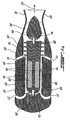
- the mixed-flow blood pump 2 comprises a stationary housing structure comprising an inflow bushing mount 56 which defines the hemisphere 16, the cylindrical member 18, the impeller housing 22, a stationary outflow stator 52, an outflow bushing mount 58, the outflow cannula 28 and the blood diffuser 32.
- Blood pump 2 further comprises a rotative impeller 50 with an impeller shaft 48 and an impeller blade 70.
- the mixed-flow blood pump 2 presents an enclosed-impeller mixed-flow configuration.
- the impeller blade 70 is a spiralling auger-type impeller blade having a constant height and being rigidly attached to the outer surface of the impeller drive shaft 48 and enclosed in the impeller housing 22.
- the impeller blade 70 fits snugly within the impeller housing 22.
- the shape (curvature and angulation) of the impeller blade 70 should be optimally designed in relation to pumping performance and other hydrodynamic considerations.
- the influence of the blade angulation on the level of shearing stresses, turbulence and cavitation responsible for red blood cell damage and increase of hemolysis rate must be carefully taken into consideration.
- the end portion of the impeller shaft 48 bearing the impeller blade 70 is slightly tapered in a direction opposite to the direction of blood flow. This contributes to create the mixed-flow operation of the pump 2. More specifically, this slight taper imparts to the blood flow both axial and radial components.
- end pivots 66 and 68 protrude.
- the function of the end pivots 66 and 68 is to support the impeller drive shaft 48 at each end.
- the end pivots 66 and 68 are respectively inserted into the respective bushing mounts 56 and 58.
- Bushing 72 is mounted on the inner face of the inflow bushing mount 56.
- bushing 74 is mounted on the adjacent face of the outflow bushing mount 58.
- the bearings formed by the bushing and pivot assemblies 66;72 and 68;74 are the only mechanical parts subject to wear. Therefore, these parts are expected to be mostly responsible for the life span of the mixed-flow blood pump 2.
- the cylindrical gap 76 separating the impeller shaft 48 and the inner surface of the cylindrical member 18 should be sufficiently thick to produce sufficient blood flow in order to increase washout and prevent clot formation.
- too large a gap 76 may either reduce the pump efficiency (by reducing the electromagnetic coupling) or result in higher hemolysis.
- the section of the impeller shaft 48 within the cylindrical member 18 is cylindrical whereby the gap 76 has a constant thickness.
- the volume of blood pumped through the second inlet 14 is typically 4 liters/minute. This is higher than the volume of blood pumped through the first inlet 12 and the cylindrical gap 76 which is typically 1 liter/minute.
- a number of benefits is associated with the higher volume blood pumped through the second inlet 14. For example, installation of the mixed-flow blood pump 2 in the left ventricle 4 of a patient with the cannula 28 extending through the aortic valve generally interferes with proper operation of the aortic valve. Optimally, the aortic valve should continue to function normally; however, in some cases, it has been observed that the aortic valve ceases to function further until it remains closed around the cannula 28.
- blood would have the tendency to collect in the region close to the aortic valve and the cannula 28 which might lead to thrombus formation and other adverse effects.
- the increased volume of blood pumped through the second inlet 14 has the effect of creating turbulence in the region within the ventricle 4 bordered by the aortic valve and the cannula 28, thus providing improved washout of this region and thereby reducing the effects of the malfunctioning aortic valve.
- the volume of blood pumped through the second inlet 14 contributes to the radial-flow operation of the mixed-flow blood pump 2.
- the volume of blood pumped through the first inlet 12 and the cylindrical gap 76 contributes to the axial-flow operation of the mixed-flow blood pump 2.
- the stationary outflow stator 52 comprises a plurality of blades shaped and disposed around the outflow bushing mount 58 to transform the rotational motion of the flow about the longitudinal axis 54 into a translational motion. Therefore, the stationary outflow stator 52 constitutes a blood flow straightener.
- the pump design should minimise shearing stress in order to minimise hemolysis.
- reduction of the rotational speed would obviously contribute to reduce hemolysis.
- reduction of the rotational speed while pumping the same volume of blood requires an increase of the volume of blood contained in the rotor zone of the pump 2.
- the volume of blood contained in the rotor zone can be increased by either increasing the diameter of the rotor zone, or alternatively minimising the volume of the central hub of the pump rotor.
- FIG. 5a shows the configuration of the region between the inflow bushing mount 56 and the impeller drive shaft 48.
- Figure 5b shows the configuration of the region between the impeller drive shaft 48 and the outflow bushing mount 58.
- the end surface 60 of the impeller drive shaft 48 is convex and generally hemispheric while the confronting surface 62 of the bushing mount 56 is concave and generally hemispheric. Forming the surfaces in this manner reduces the shearing stress placed on the blood thus minimising hemolysis (see flow 61).
- the outflow bushing mount 58 is formed with a similar convex, generally hemispheric end surface to reduce shearing stress at the outlet (see Figure 5b, in particular flow 65).
- the confronting end of the impeller shaft 48 is flat and perpendicular to the axis 54.
- end pivots 66 and 68 by which the respective ends of the impeller shaft 48 are mounted to their respective bushing mounts 56, 58 are slightly tapered in a direction opposite to blood flow. This helps prevent the creation of eddies and the collection of debris in proximity to the end pivots. Normally, a taper of the order of five degrees (5°) is adequate.
- pivot 66 has a smaller diameter free end received within the bushing 72.
- pivot 68 has a larger diameter free end received in the bushing 74.
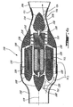
- FIG. 4b illustrates an alternative, illustrative extra-ventricular embodiment of mixed-flow blood pump 100.
- Pump 100 is adapted for use externally of the heart as a ventricle bypass/assist.
- the pump 100 would typically be implanted above the diaphragm in the thorax and would be connected to the circulation system using standard vascular grafts, a first graft 102 being attached to the inflow end of the pump and a second graft 104 being attached to the outflow end of the pump 100.
- the attemative illustrative embodiment 100 as illustrated in Figure 4b comprises a stationary housing structure including an inflow bushing mount 122, a cylindrical member 108, an impeller housing 106, a stationary outflow stator 114, an outflow bushing mount 124, an outflow cannula 150 and a blood diffuser 151.
- Blood pump 100 further comprises a rotative impeller 112 with an impeller shaft 110 and an impeller blade 116.
- the impeller blade 116 is a spiralling auger-type impeller blade rigidly connected to the impeller drive shaft 110 and enclosed in the impeller housing 106.
- a series of longitudinal ridges 118 typically five (5) evenly spaced around the pump axis 119, support the cylindrical member 108 within the impeller housing 106 thereby forming a series of longitudinal flow passages such as 120 between the cylindrical member 108 and the impeller housing 106.
- the longitudinal ridges 118 extend to meet and hold rigid the inflow bushing mount 122 with respect to the impeller housing 106 and the cylindrical member 108. Similarly, the outflow bushing mount 124 is supported within the impeller housing 106 through the stationary outflow stator 114.
- the stationary outflow stator 114 comprises a plurality of blades shaped and disposed around the outflow bushing mount 124 to transform the rotational motion of the blood flow about the longitudinal axis 119 into a translational motion. Therefore, the stationary outflow stator 114 constitutes a flow straightener.
- pivots 126 and 128 protrude.
- the end pivots 126 and 128 are respectively inserted into respective bushings 130 and 132 to support the impeller drive shaft 110 within the cylindrical conduit 108 while at the same time allowing the impeller shaft 110 to rotate freely.
- Bushing 130 is mounted on the inflow bushing mount 122.
- bushing 132 is mounted on the outflow bushing mount 124.
- annular flow passage 134 is formed between the inner surface 136 of the cylindrical member 108 and the outer surface 138 of the impeller shaft 110.
- Flow of blood through the mixed-flow pump 100 is indicated by the arrows 152-154.
- the mixed-flow blood pump 2 is actuated by means of a brushless DC (direct current) motor.
- This brushless configuration presents the advantage of minimal wear.
- Two other interesting characteristics of brushless DC motors are high rotational speed and high torque.
- the brushless DC motor includes elongated axial permanent magnets such as 78 inserted in the impeller shaft 48 and stator windings 80 embedded or housed in the cylindrical member 18.
- the cylindrical gap 76 between the outer surface of the impeller shaft 48 and the inner surface of the cylindrical member 18 must be sufficiently thick to produce sufficient blood flow in order to increase washout and prevent clot formation.
- increasing the thickness of the gap 76 decreases the efficiency of the magnetic coupling between the permanent magnets 78 and the stator windings 80.
- increase in current leads to an increase in thermal loss from the stator windings 80; this thermal loss increases as the square of the current through the stator windings 80.
- the gap 76 must be sufficiently small to provide efficient magnetic coupling between the permanent magnets 78 and the stator windings 80.
- Thermal performance is also improved given the proximate position of the stator windings 80 to the external surface 82 of the cylindrical member 18. Blood flow over the external surface 82 efficiently cools the stator windings 80. The flow of blood within the gap 76 between the impeller shaft 48 and the inner surface 84 of the cylindrical member 18 also contributes in efficiently cooling the stator windings 80.
- the alternative illustrative embodiment 100 of the mixed-flow blood pump as illustrated in Figure 4b maintains the essential electrical characteristics of the illustrative embodiment of Figure 4a with the exception that, referring to Figure 4b, the design of the pump 100 overcomes the thermal limitations by allowing for a second blood flow passage along the series of longitudinal flow passages 120 between the impeller housing 106 and the cylindrical member 108.
- Axial spacing between the impeller blade and the permanent magnets along the impeller shaft enables separate design of the DC motor and the impeller to obtain simultaneously both efficient coupling between the permanent magnets and the stator windings and sufficient pumping volume.
- the choice of materials for an implantable device is crucial and several properties of the available materials should be considered: strength, durability, hardness, elasticity, wear resistance, surface finish and biocompatibility. Biocompatibility is very important to minimise irritation, rejection and thrombogenesis. The interaction between the surface of the material and the biological tissues is very complex. In several cases, treatment of the surface with human proteins, certain drugs like heparin or other biocompatible material may considerably increase the biocompatibility and minimise thrombus formation.
- FIG. 6 schematically illustrates an embodiment of implantable VAD system including an axial-flow blood pump 2.
- the VAD system is composed of four main parts:
- VAD and TEIT Systems are well known in the art and will not be further discussed in the present specification.
- VADs ventricular assist devices
- VAD is becoming a cost effective solution considering the fact that patients are discharged from the hospitals more rapidly and may return to normal life occupations.
- several insurance companies are now reimbursing the implantation of VADs.
- the mixed-flow blood pump 2 provides an excellent bridge to heart transplant and aims at long term implant.
- the new proposed mixed-flow blood pump 2 should answer most of the remaining problems and limitations of the prior axial-flow blood pumps, especially those related to hemolysis and bleeding.
Claims (16)
- Une pompe à sang à écoulement mixte (2) présentant des caractéristiques à la fois des pompes à écoulement axial et des pompes à écoulement radial, comprenant:une structure de boítier stationnaire (22) définissant un axe longitudinal (54), un passage d'entrée du sang annulaire s'étendant axialement (76), un passage d'entrée du sang annulaire s'étendant radialement (14), une sortie de sang axiale (28), et un conduit de sang axial entre (a) les passages d'entrée du sang s'étendant axialement et radialement, et (b) la sortie de sang axiale; etune turbine rotative (50) montée dans la structure de boítier stationnaire, comprenant:un arbre de turbine (48) rotatif autour de l'axe longitudinal de la structure de boítier stationnaire, l'arbre de turbine ayant, dans le conduit de sang axial, une portion d'arbre effilée dans une direction opposée à la direction d'écoulement du sang; etune pale de turbine (70) montée sur la portion d'arbre effilée;dans lequel le passage d'entrée du sang annulaire s'étendant axialement, le passage d'entrée du sang annulaire s'étendant radialement, la portion d'arbre effilée, la pale de turbine montée sur la portion d'arbre effilée, et la sortie de sang axiale peuvent faire fonctionner la pompe à sang à écoulement mixte à un point donné d'une courbe d'efficacité hydraulique maximale reliant une vitesse de rotation spécifique de la pompe avec un diamètre spécifique de la pompe, ledit point donné étant situé dans une région de transition de la courbe d'efficacité hydraulique maximale entre les pompes à écoulement axial et les pompes à écoulement radial.
- Une pompe à sang à écoulement mixte telle que définie dans la revendication 1, dans laquelle la vitesse de rotation spécifique de la pompe et le diamètre spécifique de la pompe ont des valeurs sans dimension.
- Une pompe à sang à écoulement mixte telle que définie dans la revendication 2, dans laquelle la valeur sans dimension de la vitesse de rotation spécifique de la pompe est 1.62.
- Une pompe à sang à écoulement mixte telle que définie dans la revendication 1, dans laquelle:la structure de boítier stationnaire comporte des première (12) et seconde (13) entrées de sang annulaires espacées axialement;le passage d'entrée de sang annulaire s'étendant axialement s'étend entre la première entrée de sang annulaire et le conduit de sang axial; etle passage d'entrée de sang annulaire s'étendant radialement s'étend entre la seconde entrée de sang annulaire et le conduit de sang axial.
- Une pompe à sang à écoulement mixte telle que définie dans la revendication 4, dans laquelle:le passage d'entrée de sang annulaire s'étendant axialement comporte une portion de passage axial généralement cylindrique.
- Une pompe à sang à écoulement mixte telle que définie dans la revendication 4, dans laquelle :le passage d'entrée de sang annulaire s'étendant radialement définit un angle aigu par rapport à l'axe longitudinal de la structure de boítier stationnaire.
- Une pompe à sang à écoulement mixte telle que définie dans la revendication 5, dans laquelle:la structure de boítier stationnaire comporte un élément cylindrique avec une surface intérieure; etla portion de passage axial généralement cylindrique comporte un espacement entre l'arbre de turbine et la surface intérieure de l'élément cylindrique.
- Une pompe à sang à écoulement mixte telle que définie dans la revendication 1, dans laquelle la pale de turbine comporte un pale de turbine de type vis sans fin montée sur l'arbre de turbine.
- Une pompe à sang à écoulement mixte telle que définie dans la revendication 1, dans laquelle:la structure de boítier stationnaire comporte un élément cylindrique autour de l'arbre de turbine; etla pompe à sang à écoulement mixte comporte en outre une structure de moteur électrique comprenant :des aimants permanents noyés à l'intérieur de l'arbre de turbine; etdes enroulements électriques montés dans l'élément cylindrique de la structure de boítier stationnaire.
- Une pompe à sang à écoulement mixte telle que définie dans la revendication 7, dans laquelle:la pompe à sang à écoulement mixte comprend en outre, dans la région de l'espacement entre l'arbre de turbine et la surface intérieure de l'élément cylindrique, une structure de moteur électrique comprenant :des aimants permanents noyés dans l'arbre de turbine; et des enroulements électriques montés dans l'élément cylindrique de la structure de boítier stationnaire.
- Une pompe à sang à écoulement mixte telle que définie dans la revendication 1, dans laquelle:l'arbre de turbine comporte des première et second extrémités opposées et des premier et second pivots d'extrémités opposées; etla structure de boítier stationnaire comprend des premier et second supports de coussinet respectivement aux première et seconde extrémités de l'arbre de turbine pour recevoir les premier et second pivots d'extrémités opposées.
- Une pompe à sang à écoulement mixte telle que définie dans la revendication 11, dans laquelle:le premier pivot est légèrement effilé dans une direction opposée à la direction d'écoulement du sang et comprend un extrémité libre de plus petit diamètre;le premier support de coussinet comprend un premier coussinet pour recevoir l'extrémité libre de plus petit diamètre du premier pivot;le premier support de coussinet comprend une surface concave généralement hémisphérique dans la région du premier coussinet; etla première extrémité de l'arbre de turbine est convexe et généralement hémisphérique.
- Une pompe à sang à écoulement mixte telle que définie dans la revendication 11, dans laquelle:le second pivot est légèrement effilé dans une direction opposée à la direction d'écoulement de sang et comporte un extrémité libre de plus grand diamètre;le second support de coussinet comporte un second coussinet pour recevoir l'extrémité libre de plus grand diamètre du second pivot;le second support de coussinet comprend une surface convexe généralement hémisphérique dans la région du second coussinet; etla seconde extrémité de l'arbre de turbine est généralement plate.
- Une pompe à sang à écoulement mixte telle que définie dans la revendication 1, dans laquelle :la structure de boítier stationnaire comprend un boítier de turbine autour de la pale de turbine, le boítier de turbine ayant une surface intérieure dans laquelle la pale de turbine est ajustée.
- Une pompe à sang à écoulement mixte telle que définie dans la revendication 11, dans laquelle:la pale de turbine a une hauteur constante.
- Une pompe à sang à écoulement mixte telle que définie dans la revendication 1, dans laquelle:une structure de redresseur d'écoulement reliée au boítier de turbine pour redresser l'écoulement de sang en provenance de la pale de turbine; etune structure de diffuseur d'écoulement en aval de la structure de redresseur d'écoulement pour diffuser l'écoulement de sang redressé.
Applications Claiming Priority (3)
| Application Number | Priority Date | Filing Date | Title |
|---|---|---|---|
| CA002374989A CA2374989A1 (fr) | 2002-03-08 | 2002-03-08 | Dispositif d'assistance ventriculaire comprenant une pompe a sang hybride a double entree |
| CA2374989 | 2002-03-08 | ||
| PCT/CA2003/000103 WO2003075981A1 (fr) | 2002-03-08 | 2003-01-27 | Pompe sanguine helicocentrifuge a double canal d'entree |
Publications (2)
| Publication Number | Publication Date |
|---|---|
| EP1485144A1 EP1485144A1 (fr) | 2004-12-15 |
| EP1485144B1 true EP1485144B1 (fr) | 2005-07-27 |
Family
ID=27792825
Family Applications (1)
| Application Number | Title | Priority Date | Filing Date |
|---|---|---|---|
| EP03700754A Expired - Lifetime EP1485144B1 (fr) | 2002-03-08 | 2003-01-27 | Pompe sanguine helicocentrifuge a double canal d'entree |
Country Status (7)
| Country | Link |
|---|---|
| US (1) | US20050107657A1 (fr) |
| EP (1) | EP1485144B1 (fr) |
| AT (1) | ATE300321T1 (fr) |
| AU (1) | AU2003202357A1 (fr) |
| CA (1) | CA2374989A1 (fr) |
| DE (1) | DE60301135T2 (fr) |
| WO (1) | WO2003075981A1 (fr) |
Families Citing this family (36)
| Publication number | Priority date | Publication date | Assignee | Title |
|---|---|---|---|---|
| JP4248811B2 (ja) * | 2002-07-11 | 2009-04-02 | 健太郎 長田 | 締め付けバンド |
| US7014605B2 (en) * | 2004-04-15 | 2006-03-21 | Paul Weatherbee | Pulsatile blood pumping system |
| US8419609B2 (en) | 2005-10-05 | 2013-04-16 | Heartware Inc. | Impeller for a rotary ventricular assist device |
| EP2438936B1 (fr) | 2005-06-06 | 2015-10-07 | The Cleveland Clinic Foundation | Pompe sanguine |
| AU2013257469B2 (en) * | 2005-10-05 | 2016-03-17 | Heartware, Inc. | Axial flow pump with multi-grooved rotor |
| US8672611B2 (en) | 2006-01-13 | 2014-03-18 | Heartware, Inc. | Stabilizing drive for contactless rotary blood pump impeller |
| AU2007207782B2 (en) | 2006-01-13 | 2012-09-27 | Heartware, Inc. | Rotary blood pump |
| US8376926B2 (en) * | 2007-11-29 | 2013-02-19 | Micromed Technology, Inc. | Rotary blood pump |
| JP5571087B2 (ja) * | 2008-09-26 | 2014-08-13 | ワールドハート インコーポレーテッド | 磁気浮上血液ポンプ及び該ポンプの小型化を可能にする最適化方法 |
| FR2955499B1 (fr) * | 2010-01-28 | 2013-06-14 | Fineheart | " pompe cardiaque autonome, et procede mis en oeuvre dans une telle pompe". |
| TW201217010A (en) * | 2010-06-22 | 2012-05-01 | Thoratec Corp | Apparatus and method for modifying pressure-flow characteristics of a pump |
| EP3056231A1 (fr) | 2010-10-13 | 2016-08-17 | Thoratec Corporation | Pompe a sang |
| EP2707053B1 (fr) * | 2011-05-13 | 2016-11-30 | Heartware, Inc. | Pompe à sang vasculaire et procédé d'implantation |
| CN103747815A (zh) | 2011-07-28 | 2014-04-23 | 好心公司 | 可移除的心脏泵以及利用这种泵所实施的方法 |
| US8864643B2 (en) | 2011-10-13 | 2014-10-21 | Thoratec Corporation | Pump and method for mixed flow blood pumping |
| WO2013134319A1 (fr) | 2012-03-05 | 2013-09-12 | Justin Aron Callaway | Pompe médicale modulaire implantable |
| WO2013145135A1 (fr) * | 2012-03-27 | 2013-10-03 | 株式会社サンメディカル技術研究所 | Système de dispositif d'assistance ventriculaire |
| CN103957958B (zh) | 2012-03-27 | 2016-06-01 | 株式会社太阳医疗技术研究所 | 辅助人工心脏泵 |
| EP2942527B1 (fr) * | 2013-01-07 | 2018-04-11 | National University Corporation Kobe University | Pompe sanguine à flux axial |
| DE102013013700A1 (de) * | 2013-04-05 | 2014-10-09 | CircuLite GmbH | Implantierbare Blutpumpe, Blutpumpensystem und Verfahren zur Datenübertragung in einem Blutpumpensystem |
| FR3004113A1 (fr) * | 2013-04-08 | 2014-10-10 | Harobase Innovations Inc | Ensemble pour implanter une pompe d'assistance cardiaque ventriculaire gauche |
| FR3004111A1 (fr) * | 2013-04-08 | 2014-10-10 | Harobase Innovations Inc | Pompe d'assistance cardiaque ventriculaire gauche |
| EP2983732B1 (fr) * | 2013-04-08 | 2022-02-23 | Systol Dynamics | Pompe d'assistance cardiaque pour le ventriculaire gauche et procédés associés |
| US9345824B2 (en) * | 2014-07-07 | 2016-05-24 | Assistocor Gmbh & Co Kg | Ventricular assist device |
| WO2016086137A1 (fr) * | 2014-11-26 | 2016-06-02 | Thoratec Corporation | Pompe et procédé de pompage de sang hélicocentrifuge |
| EP3069739B1 (fr) * | 2015-03-18 | 2020-12-16 | Abiomed Europe GmbH | Pompe sanguine |
| US10857273B2 (en) | 2016-07-21 | 2020-12-08 | Tc1 Llc | Rotary seal for cantilevered rotor pump and methods for axial flow blood pumping |
| WO2018031741A1 (fr) | 2016-08-12 | 2018-02-15 | Tc1 Llc | Dispositifs et procédés de surveillance des performances d'un palier et d'un joint |
| DE102018201030A1 (de) | 2018-01-24 | 2019-07-25 | Kardion Gmbh | Magnetkuppelelement mit magnetischer Lagerungsfunktion |
| DE102018208540A1 (de) * | 2018-05-30 | 2019-12-05 | Kardion Gmbh | Pumpengehäusevorrichtung und Verfahren zum Herstellen einer Pumpengehäusevorrichtung und Pumpe mit einer Pumpengehäusevorrichtung |
| EP3581216A1 (fr) * | 2018-06-11 | 2019-12-18 | Universität Zürich | Pompe sanguine pour l'assistance circulatoire mécanique des patients opérés d'un fontan |
| DE102018211327A1 (de) | 2018-07-10 | 2020-01-16 | Kardion Gmbh | Laufrad für ein implantierbares, vaskuläres Unterstützungssystem |
| EP3682918A1 (fr) * | 2019-01-21 | 2020-07-22 | Berlin Heart GmbH | Pompe à fluide |
| DE102020102474A1 (de) | 2020-01-31 | 2021-08-05 | Kardion Gmbh | Pumpe zum Fördern eines Fluids und Verfahren zum Herstellen einer Pumpe |
| CN115591105B (zh) * | 2021-07-07 | 2023-08-15 | 上海焕擎医疗科技有限公司 | 一种心脏辅助装置的叶轮及心脏辅助装置 |
| CN117839060A (zh) * | 2022-07-08 | 2024-04-09 | 深圳核心医疗科技股份有限公司 | 驱动机构和血泵 |
Family Cites Families (68)
| Publication number | Priority date | Publication date | Assignee | Title |
|---|---|---|---|---|
| FR2451480A1 (fr) * | 1979-03-16 | 1980-10-10 | Belenger Jacques | Pompe centrifuge medicale |
| JPS6022944B2 (ja) * | 1980-11-10 | 1985-06-05 | 日本ゼオン株式会社 | 血液用ポンプ装置 |
| US4688998A (en) * | 1981-03-18 | 1987-08-25 | Olsen Don B | Magnetically suspended and rotated impellor pump apparatus and method |
| EP0060569B1 (fr) | 1981-03-18 | 1990-12-19 | Günther Walter Otto Bramm | Appareil de pompage avec rotor suspendu et entraîné magnétiquement |
| US4625712A (en) * | 1983-09-28 | 1986-12-02 | Nimbus, Inc. | High-capacity intravascular blood pump utilizing percutaneous access |
| JPS60242860A (ja) * | 1984-05-18 | 1985-12-02 | 日本ゼオン株式会社 | 血液ポンプの成形方法 |
| US4606698A (en) * | 1984-07-09 | 1986-08-19 | Mici Limited Partnership Iv | Centrifugal blood pump with tapered shaft seal |
| US4589822A (en) * | 1984-07-09 | 1986-05-20 | Mici Limited Partnership Iv | Centrifugal blood pump with impeller |
| US4643641A (en) * | 1984-09-10 | 1987-02-17 | Mici Limited Partnership Iv | Method and apparatus for sterilization of a centrifugal pump |
| US4753221A (en) * | 1986-10-22 | 1988-06-28 | Intravascular Surgical Instruments, Inc. | Blood pumping catheter and method of use |
| US4779614A (en) * | 1987-04-09 | 1988-10-25 | Nimbus Medical, Inc. | Magnetically suspended rotor axial flow blood pump |
| US4817586A (en) * | 1987-11-24 | 1989-04-04 | Nimbus Medical, Inc. | Percutaneous bloom pump with mixed-flow output |
| US4846152A (en) * | 1987-11-24 | 1989-07-11 | Nimbus Medical, Inc. | Single-stage axial flow blood pump |
| US4895557A (en) * | 1987-12-07 | 1990-01-23 | Nimbus Medical, Inc. | Drive mechanism for powering intravascular blood pumps |
| US4994078A (en) * | 1988-02-17 | 1991-02-19 | Jarvik Robert K | Intraventricular artificial hearts and methods of their surgical implantation and use |
| US4981414A (en) * | 1988-05-27 | 1991-01-01 | Sheets Herman E | Method and apparatus for producing fluid pressure and controlling boundary layer |
| US4908012A (en) * | 1988-08-08 | 1990-03-13 | Nimbus Medical, Inc. | Chronic ventricular assist system |
| US4898518A (en) * | 1988-08-31 | 1990-02-06 | Minnesota Mining & Manufacturing Company | Shaft driven disposable centrifugal pump |
| US4964864A (en) * | 1988-09-27 | 1990-10-23 | American Biomed, Inc. | Heart assist pump |
| US4944722A (en) * | 1989-02-23 | 1990-07-31 | Nimbus Medical, Inc. | Percutaneous axial flow blood pump |
| US4984972A (en) * | 1989-10-24 | 1991-01-15 | Minnesota Mining And Manufacturing Co. | Centrifugal blood pump |
| US5098256A (en) * | 1989-11-21 | 1992-03-24 | The Cleveland Clinic Foundation | Viscous seal blood pump |
| US5112202A (en) * | 1990-01-31 | 1992-05-12 | Ntn Corporation | Turbo pump with magnetically supported impeller |
| US5211546A (en) * | 1990-05-29 | 1993-05-18 | Nu-Tech Industries, Inc. | Axial flow blood pump with hydrodynamically suspended rotor |
| US5112200A (en) * | 1990-05-29 | 1992-05-12 | Nu-Tech Industries, Inc. | Hydrodynamically suspended rotor axial flow blood pump |
| US5195877A (en) * | 1990-10-05 | 1993-03-23 | Kletschka Harold D | Fluid pump with magnetically levitated impeller |
| US5470208A (en) * | 1990-10-05 | 1995-11-28 | Kletschka; Harold D. | Fluid pump with magnetically levitated impeller |
| US5205721A (en) | 1991-02-13 | 1993-04-27 | Nu-Tech Industries, Inc. | Split stator for motor/blood pump |
| US5316440A (en) * | 1991-05-10 | 1994-05-31 | Terumo Kabushiki Kaisha | Blood pump apparatus |
| JP3181340B2 (ja) * | 1991-11-19 | 2001-07-03 | 康裕 福井 | 一体型人工心肺 |
| US6387125B1 (en) * | 1992-06-23 | 2002-05-14 | Sun Medical Technology Research Corporation | Auxiliary artificial heart of an embedded type |
| US5290227A (en) * | 1992-08-06 | 1994-03-01 | Pasque Michael K | Method of implanting blood pump in ascending aorta or main pulmonary artery |
| US5399074A (en) * | 1992-09-04 | 1995-03-21 | Kyocera Corporation | Motor driven sealless blood pump |
| JP2569419B2 (ja) * | 1993-02-18 | 1997-01-08 | 工業技術院長 | 人工心臓用ポンプ |
| DE4321260C1 (de) * | 1993-06-25 | 1995-03-09 | Westphal Dieter Dipl Ing Dipl | Blutpumpe als Zentrifugalpumpe |
| US5527159A (en) * | 1993-11-10 | 1996-06-18 | The United States Of America As Represented By The Administrator Of The National Aeronautics And Space Administration | Rotary blood pump |
| US5947892A (en) * | 1993-11-10 | 1999-09-07 | Micromed Technology, Inc. | Rotary blood pump |
| US5507629A (en) * | 1994-06-17 | 1996-04-16 | Jarvik; Robert | Artificial hearts with permanent magnet bearings |
| US5613935A (en) * | 1994-12-16 | 1997-03-25 | Jarvik; Robert | High reliability cardiac assist system |
| US5707218A (en) * | 1995-04-19 | 1998-01-13 | Nimbus, Inc. | Implantable electric axial-flow blood pump with blood cooled bearing |
| US5588812A (en) * | 1995-04-19 | 1996-12-31 | Nimbus, Inc. | Implantable electric axial-flow blood pump |
| US5824070A (en) * | 1995-10-30 | 1998-10-20 | Jarvik; Robert | Hybrid flow blood pump |
| US5840070A (en) * | 1996-02-20 | 1998-11-24 | Kriton Medical, Inc. | Sealless rotary blood pump |
| US5911685A (en) * | 1996-04-03 | 1999-06-15 | Guidant Corporation | Method and apparatus for cardiac blood flow assistance |
| DE19613564C1 (de) * | 1996-04-04 | 1998-01-08 | Guenter Prof Dr Rau | Intravasale Blutpumpe |
| US6015272A (en) * | 1996-06-26 | 2000-01-18 | University Of Pittsburgh | Magnetically suspended miniature fluid pump and method of designing the same |
| US6244835B1 (en) * | 1996-06-26 | 2001-06-12 | James F. Antaki | Blood pump having a magnetically suspended rotor |
| US5851174A (en) * | 1996-09-17 | 1998-12-22 | Robert Jarvik | Cardiac support device |
| JP4016441B2 (ja) * | 1996-10-02 | 2007-12-05 | 株式会社ジェイ・エム・エス | ターボ式血液ポンプ |
| US5964694A (en) * | 1997-04-02 | 1999-10-12 | Guidant Corporation | Method and apparatus for cardiac blood flow assistance |
| US6093001A (en) * | 1997-05-02 | 2000-07-25 | University Of Pittsburgh | Rotary pump having a bearing which dissipates heat |
| AUPO902797A0 (en) * | 1997-09-05 | 1997-10-02 | Cortronix Pty Ltd | A rotary blood pump with hydrodynamically suspended impeller |
| CA2206644A1 (fr) * | 1997-05-30 | 1998-11-30 | L. Conrad Pelletier | Dispositif d'assistance ventriculaire comprenant une pompe a sang axiale a roue fermee |
| US6250880B1 (en) * | 1997-09-05 | 2001-06-26 | Ventrassist Pty. Ltd | Rotary pump with exclusively hydrodynamically suspended impeller |
| US5928131A (en) * | 1997-11-26 | 1999-07-27 | Vascor, Inc. | Magnetically suspended fluid pump and control system |
| WO1999034847A2 (fr) * | 1998-01-12 | 1999-07-15 | Klein Enrique J | Hemopompe sans joint amelioree |
| JPH11244376A (ja) * | 1998-02-27 | 1999-09-14 | Kyocera Corp | 血液ポンプ |
| US6176822B1 (en) * | 1998-03-31 | 2001-01-23 | Impella Cardiotechnik Gmbh | Intracardiac blood pump |
| US6123659A (en) * | 1999-01-26 | 2000-09-26 | Nimbus Inc. | Blood pump with profiled outflow region |
| US6018208A (en) * | 1999-01-26 | 2000-01-25 | Nimbus, Inc. | Articulated motor stator assembly for a pump |
| DE50010708D1 (de) * | 1999-04-20 | 2005-08-18 | Berlin Heart Ag | Vorrichtung zur axialen Förderung von fluiden Medien |
| US6247892B1 (en) * | 1999-07-26 | 2001-06-19 | Impsa International Inc. | Continuous flow rotary pump |
| JP2001207988A (ja) * | 2000-01-26 | 2001-08-03 | Nipro Corp | 磁気駆動型軸流ポンプ |
| DE20004136U1 (de) * | 2000-03-04 | 2000-12-14 | Krankenhausbetr Sgesellschaft | Blutpumpe |
| US6439845B1 (en) * | 2000-03-23 | 2002-08-27 | Kidney Replacement Services, P.C. | Blood pump |
| AT412065B (de) * | 2000-03-24 | 2004-09-27 | Schima Heinrich Dr | Rotationspumpe mit hydraulisch gelagertem rotor |
| JP2001336528A (ja) * | 2000-05-25 | 2001-12-07 | Ntn Corp | 磁気浮上装置 |
| US6761532B2 (en) * | 2001-03-14 | 2004-07-13 | Vascor, Inc. | Touch down of blood pump impellers |
-
2002
- 2002-03-08 CA CA002374989A patent/CA2374989A1/fr not_active Abandoned
-
2003
- 2003-01-27 AT AT03700754T patent/ATE300321T1/de not_active IP Right Cessation
- 2003-01-27 WO PCT/CA2003/000103 patent/WO2003075981A1/fr not_active Application Discontinuation
- 2003-01-27 EP EP03700754A patent/EP1485144B1/fr not_active Expired - Lifetime
- 2003-01-27 DE DE60301135T patent/DE60301135T2/de not_active Expired - Fee Related
- 2003-01-27 US US10/499,801 patent/US20050107657A1/en not_active Abandoned
- 2003-01-27 AU AU2003202357A patent/AU2003202357A1/en not_active Abandoned
Also Published As
| Publication number | Publication date |
|---|---|
| CA2374989A1 (fr) | 2003-09-08 |
| DE60301135D1 (de) | 2005-09-01 |
| US20050107657A1 (en) | 2005-05-19 |
| ATE300321T1 (de) | 2005-08-15 |
| AU2003202357A1 (en) | 2003-09-22 |
| EP1485144A1 (fr) | 2004-12-15 |
| DE60301135T2 (de) | 2006-04-20 |
| WO2003075981A1 (fr) | 2003-09-18 |
Similar Documents
| Publication | Publication Date | Title |
|---|---|---|
| EP1485144B1 (fr) | Pompe sanguine helicocentrifuge a double canal d'entree | |
| US20050250975A1 (en) | Blood pump with dual inlet passages | |
| WO1998053864A1 (fr) | Appareil d'assistance ventriculaire avec pompe a sang axiale a rotor ferme | |
| US11185678B2 (en) | Blood pump | |
| US9162018B2 (en) | Cardiac pump | |
| Reul et al. | Blood pumps for circulatory support | |
| US5290227A (en) | Method of implanting blood pump in ascending aorta or main pulmonary artery | |
| AU678697B2 (en) | Cannula pumps for temporary cardiac support | |
| US20070083077A1 (en) | Total artificial heart system for auto-regulating flow and pressure balance | |
| JPH1099429A (ja) | ターボ式血液ポンプ | |
| Jarvik | Jarvik 2000 pump technology and miniaturization | |
| US20220296852A1 (en) | Mammalian body implantable fluid flow influencing device | |
| Wampler et al. | A sealless centrifugal blood pump with passive magnetic and hydrodynamic bearings | |
| Olia et al. | Preclinical performance of a pediatric mechanical circulatory support device: The PediaFlow ventricular assist device | |
| CA2472088A1 (fr) | Pompe sanguine helicocentrifuge a double canal d'entree | |
| US20230211143A1 (en) | Left ventricle unloading device | |
| CA2292432A1 (fr) | Appareil d'assistance ventriculaire avec pompe a sang axiale a rotor ferme | |
| CA2517236A1 (fr) | Pompe a sang a structure d'appui en tronc de cone | |
| Yamane et al. | Fluid dynamics of turbo pumps for artificial hearts | |
| Benkowski et al. | Rotary blood pump | |
| Golding et al. | Centrifugal pumps—now and the future | |
| Kawahito et al. | Phase 1 ex vivo studies of the Baylor/NASA axial flow ventricular assist device | |
| Sakuma et al. | Development of a Seal-Less Motor-Driven Centrifugal Blood Pump (Baylor Gyro Pump) |
Legal Events
| Date | Code | Title | Description |
|---|---|---|---|
| PUAI | Public reference made under article 153(3) epc to a published international application that has entered the european phase |
Free format text: ORIGINAL CODE: 0009012 |
|
| 17P | Request for examination filed |
Effective date: 20041008 |
|
| AK | Designated contracting states |
Kind code of ref document: A1 Designated state(s): AT BE BG CH CY CZ DE DK EE ES FI FR GB GR HU IE IT LI LU MC NL PT SE SI SK TR |
|
| AX | Request for extension of the european patent |
Extension state: AL LT LV MK RO |
|
| GRAP | Despatch of communication of intention to grant a patent |
Free format text: ORIGINAL CODE: EPIDOSNIGR1 |
|
| GRAS | Grant fee paid |
Free format text: ORIGINAL CODE: EPIDOSNIGR3 |
|
| GRAA | (expected) grant |
Free format text: ORIGINAL CODE: 0009210 |
|
| AK | Designated contracting states |
Kind code of ref document: B1 Designated state(s): AT BE BG CH CY CZ DE DK EE ES FI FR GB GR HU IE IT LI LU MC NL PT SE SI SK TR |
|
| PG25 | Lapsed in a contracting state [announced via postgrant information from national office to epo] |
Ref country code: IT Free format text: LAPSE BECAUSE OF FAILURE TO SUBMIT A TRANSLATION OF THE DESCRIPTION OR TO PAY THE FEE WITHIN THE PRESCRIBED TIME-LIMIT;WARNING: LAPSES OF ITALIAN PATENTS WITH EFFECTIVE DATE BEFORE 2007 MAY HAVE OCCURRED AT ANY TIME BEFORE 2007. THE CORRECT EFFECTIVE DATE MAY BE DIFFERENT FROM THE ONE RECORDED. Effective date: 20050727 Ref country code: NL Free format text: LAPSE BECAUSE OF FAILURE TO SUBMIT A TRANSLATION OF THE DESCRIPTION OR TO PAY THE FEE WITHIN THE PRESCRIBED TIME-LIMIT Effective date: 20050727 Ref country code: SK Free format text: LAPSE BECAUSE OF FAILURE TO SUBMIT A TRANSLATION OF THE DESCRIPTION OR TO PAY THE FEE WITHIN THE PRESCRIBED TIME-LIMIT Effective date: 20050727 Ref country code: CH Free format text: LAPSE BECAUSE OF FAILURE TO SUBMIT A TRANSLATION OF THE DESCRIPTION OR TO PAY THE FEE WITHIN THE PRESCRIBED TIME-LIMIT Effective date: 20050727 Ref country code: FI Free format text: LAPSE BECAUSE OF FAILURE TO SUBMIT A TRANSLATION OF THE DESCRIPTION OR TO PAY THE FEE WITHIN THE PRESCRIBED TIME-LIMIT Effective date: 20050727 Ref country code: LI Free format text: LAPSE BECAUSE OF FAILURE TO SUBMIT A TRANSLATION OF THE DESCRIPTION OR TO PAY THE FEE WITHIN THE PRESCRIBED TIME-LIMIT Effective date: 20050727 Ref country code: CZ Free format text: LAPSE BECAUSE OF FAILURE TO SUBMIT A TRANSLATION OF THE DESCRIPTION OR TO PAY THE FEE WITHIN THE PRESCRIBED TIME-LIMIT Effective date: 20050727 Ref country code: SI Free format text: LAPSE BECAUSE OF FAILURE TO SUBMIT A TRANSLATION OF THE DESCRIPTION OR TO PAY THE FEE WITHIN THE PRESCRIBED TIME-LIMIT Effective date: 20050727 Ref country code: AT Free format text: LAPSE BECAUSE OF FAILURE TO SUBMIT A TRANSLATION OF THE DESCRIPTION OR TO PAY THE FEE WITHIN THE PRESCRIBED TIME-LIMIT Effective date: 20050727 Ref country code: BE Free format text: LAPSE BECAUSE OF FAILURE TO SUBMIT A TRANSLATION OF THE DESCRIPTION OR TO PAY THE FEE WITHIN THE PRESCRIBED TIME-LIMIT Effective date: 20050727 |
|
| REG | Reference to a national code |
Ref country code: GB Ref legal event code: FG4D |
|
| REG | Reference to a national code |
Ref country code: CH Ref legal event code: EP |
|
| REG | Reference to a national code |
Ref country code: IE Ref legal event code: FG4D |
|
| REF | Corresponds to: |
Ref document number: 60301135 Country of ref document: DE Date of ref document: 20050901 Kind code of ref document: P |
|
| PG25 | Lapsed in a contracting state [announced via postgrant information from national office to epo] |
Ref country code: BG Free format text: LAPSE BECAUSE OF FAILURE TO SUBMIT A TRANSLATION OF THE DESCRIPTION OR TO PAY THE FEE WITHIN THE PRESCRIBED TIME-LIMIT Effective date: 20051027 Ref country code: GR Free format text: LAPSE BECAUSE OF FAILURE TO SUBMIT A TRANSLATION OF THE DESCRIPTION OR TO PAY THE FEE WITHIN THE PRESCRIBED TIME-LIMIT Effective date: 20051027 Ref country code: SE Free format text: LAPSE BECAUSE OF FAILURE TO SUBMIT A TRANSLATION OF THE DESCRIPTION OR TO PAY THE FEE WITHIN THE PRESCRIBED TIME-LIMIT Effective date: 20051027 Ref country code: DK Free format text: LAPSE BECAUSE OF FAILURE TO SUBMIT A TRANSLATION OF THE DESCRIPTION OR TO PAY THE FEE WITHIN THE PRESCRIBED TIME-LIMIT Effective date: 20051027 |
|
| PG25 | Lapsed in a contracting state [announced via postgrant information from national office to epo] |
Ref country code: ES Free format text: LAPSE BECAUSE OF FAILURE TO SUBMIT A TRANSLATION OF THE DESCRIPTION OR TO PAY THE FEE WITHIN THE PRESCRIBED TIME-LIMIT Effective date: 20051107 |
|
| PG25 | Lapsed in a contracting state [announced via postgrant information from national office to epo] |
Ref country code: PT Free format text: LAPSE BECAUSE OF FAILURE TO SUBMIT A TRANSLATION OF THE DESCRIPTION OR TO PAY THE FEE WITHIN THE PRESCRIBED TIME-LIMIT Effective date: 20051227 |
|
| PG25 | Lapsed in a contracting state [announced via postgrant information from national office to epo] |
Ref country code: IE Free format text: LAPSE BECAUSE OF NON-PAYMENT OF DUE FEES Effective date: 20060127 |
|
| PG25 | Lapsed in a contracting state [announced via postgrant information from national office to epo] |
Ref country code: HU Free format text: LAPSE BECAUSE OF FAILURE TO SUBMIT A TRANSLATION OF THE DESCRIPTION OR TO PAY THE FEE WITHIN THE PRESCRIBED TIME-LIMIT Effective date: 20060128 |
|
| PG25 | Lapsed in a contracting state [announced via postgrant information from national office to epo] |
Ref country code: LU Free format text: LAPSE BECAUSE OF NON-PAYMENT OF DUE FEES Effective date: 20060131 Ref country code: MC Free format text: LAPSE BECAUSE OF NON-PAYMENT OF DUE FEES Effective date: 20060131 |
|
| REG | Reference to a national code |
Ref country code: CH Ref legal event code: PL |
|
| NLV1 | Nl: lapsed or annulled due to failure to fulfill the requirements of art. 29p and 29m of the patents act | ||
| ET | Fr: translation filed | ||
| PLBE | No opposition filed within time limit |
Free format text: ORIGINAL CODE: 0009261 |
|
| STAA | Information on the status of an ep patent application or granted ep patent |
Free format text: STATUS: NO OPPOSITION FILED WITHIN TIME LIMIT |
|
| 26N | No opposition filed |
Effective date: 20060428 |
|
| REG | Reference to a national code |
Ref country code: IE Ref legal event code: MM4A |
|
| PGFP | Annual fee paid to national office [announced via postgrant information from national office to epo] |
Ref country code: DE Payment date: 20080208 Year of fee payment: 6 Ref country code: GB Payment date: 20080129 Year of fee payment: 6 |
|
| PG25 | Lapsed in a contracting state [announced via postgrant information from national office to epo] |
Ref country code: EE Free format text: LAPSE BECAUSE OF FAILURE TO SUBMIT A TRANSLATION OF THE DESCRIPTION OR TO PAY THE FEE WITHIN THE PRESCRIBED TIME-LIMIT Effective date: 20050727 |
|
| PG25 | Lapsed in a contracting state [announced via postgrant information from national office to epo] |
Ref country code: TR Free format text: LAPSE BECAUSE OF FAILURE TO SUBMIT A TRANSLATION OF THE DESCRIPTION OR TO PAY THE FEE WITHIN THE PRESCRIBED TIME-LIMIT Effective date: 20050727 |
|
| PGFP | Annual fee paid to national office [announced via postgrant information from national office to epo] |
Ref country code: FR Payment date: 20080125 Year of fee payment: 6 |
|
| PG25 | Lapsed in a contracting state [announced via postgrant information from national office to epo] |
Ref country code: CY Free format text: LAPSE BECAUSE OF FAILURE TO SUBMIT A TRANSLATION OF THE DESCRIPTION OR TO PAY THE FEE WITHIN THE PRESCRIBED TIME-LIMIT Effective date: 20050727 |
|
| GBPC | Gb: european patent ceased through non-payment of renewal fee |
Effective date: 20090127 |
|
| PG25 | Lapsed in a contracting state [announced via postgrant information from national office to epo] |
Ref country code: DE Free format text: LAPSE BECAUSE OF NON-PAYMENT OF DUE FEES Effective date: 20090801 |
|
| REG | Reference to a national code |
Ref country code: FR Ref legal event code: ST Effective date: 20091030 |
|
| PG25 | Lapsed in a contracting state [announced via postgrant information from national office to epo] |
Ref country code: GB Free format text: LAPSE BECAUSE OF NON-PAYMENT OF DUE FEES Effective date: 20090127 |
|
| PG25 | Lapsed in a contracting state [announced via postgrant information from national office to epo] |
Ref country code: FR Free format text: LAPSE BECAUSE OF NON-PAYMENT OF DUE FEES Effective date: 20090202 |