EP1484873A1 - Verfahren und System zur Durchführung schnurloser Kommunikation durch Erzeugen und Senden eines Zeitinformation und Sendeabfolge beinhaltenden Zeiteinteilungsplans - Google Patents
Verfahren und System zur Durchführung schnurloser Kommunikation durch Erzeugen und Senden eines Zeitinformation und Sendeabfolge beinhaltenden Zeiteinteilungsplans Download PDFInfo
- Publication number
- EP1484873A1 EP1484873A1 EP20040013178 EP04013178A EP1484873A1 EP 1484873 A1 EP1484873 A1 EP 1484873A1 EP 20040013178 EP20040013178 EP 20040013178 EP 04013178 A EP04013178 A EP 04013178A EP 1484873 A1 EP1484873 A1 EP 1484873A1
- Authority
- EP
- European Patent Office
- Prior art keywords
- wireless terminal
- data
- schedule map
- transmission
- frame
- Prior art date
- Legal status (The legal status is an assumption and is not a legal conclusion. Google has not performed a legal analysis and makes no representation as to the accuracy of the status listed.)
- Granted
Links
Images


Classifications
-
- H—ELECTRICITY
- H04—ELECTRIC COMMUNICATION TECHNIQUE
- H04W—WIRELESS COMMUNICATION NETWORKS
- H04W74/00—Wireless channel access, e.g. scheduled or random access
- H04W74/04—Scheduled or contention-free access
-
- H—ELECTRICITY
- H04—ELECTRIC COMMUNICATION TECHNIQUE
- H04W—WIRELESS COMMUNICATION NETWORKS
- H04W72/00—Local resource management
- H04W72/12—Wireless traffic scheduling
- H04W72/121—Wireless traffic scheduling for groups of terminals or users
-
- H—ELECTRICITY
- H04—ELECTRIC COMMUNICATION TECHNIQUE
- H04W—WIRELESS COMMUNICATION NETWORKS
- H04W84/00—Network topologies
- H04W84/18—Self-organising networks, e.g. ad-hoc networks or sensor networks
-
- H—ELECTRICITY
- H04—ELECTRIC COMMUNICATION TECHNIQUE
- H04W—WIRELESS COMMUNICATION NETWORKS
- H04W72/00—Local resource management
- H04W72/12—Wireless traffic scheduling
- H04W72/1263—Mapping of traffic onto schedule, e.g. scheduled allocation or multiplexing of flows
- H04W72/1268—Mapping of traffic onto schedule, e.g. scheduled allocation or multiplexing of flows of uplink data flows
Definitions
- the present invention relates to a local communication system and a method in a wireless communication system, and more particularly to a local communication system and a method for allowing a plurality of terminals to perform wireless communication.
- a local area network is a network developed from a wire-based communication network.
- the local area network is a small or medium scale of a wire network constructed by means of a coaxial cable, so that terminals in the local area network can share or exchange data with each other. Since the local area network as described above is a wire-based network, it is by its nature limited in mobility.
- Wireless communication technology may be classified into various methods according to a classification standard into a frequency division multiplexing (FDM) method using a frequency division, and a code division multiplexing (CDM) method using a code division.
- FDM frequency division multiplexing
- CDM code division multiplexing
- a CDMA mobile communication system using the CDM method is currently in use and classified into a synchronous CDMA and an asynchronous CDMA.
- CDMA synchronous code division multiple access
- a 1x EV-DO system capable of transmitting high speed data has currently reached its commercialization stage.
- a 1x EV-DO system capable of providing both a voice and high-rate data has cbeen developed.
- Data provided in various fields is gradually being transmitted in large quantities.
- high definition (HD) televisions are now available and require high definition services to be provided.
- high quality of image data transmission is also being required together with the appearance of digital radio data (DVD).
- DVD digital radio data
- a method having been proposed for a local wireless communication system may include a wireless local area network (WLAN) and an ad-hoc network.
- WLAN wireless local area network
- ad-hoc network a wireless local area network
- wire-based connections such as a coaxial cable are no longer required, and communication is performed by means of a radio frequency (RF) transmission.
- RF radio frequency
- a specific node accesses another node on a competition basis.
- the mechanism for the connection is very complicated. Accordingly, when a specific terminal requires a high quality data transmission as described above, there exist many limitations in the wireless local area network. This is because the processing time required for the data transmission increases as the control mechanism increases in complication, or an expensive apparatus capable of quickly performing a complicated process is required.
- a specific terminal transmits information to adjacent terminals, and the adjacent terminals retransmit the information to a further destination.
- position change and path change of the adjacent terminals may frequently occur. Accordingly, a time delay or a transmission failure for a transmitted service may occur. That is, when a large quantity of data must be transmitted at a high speed as described above, a desired quality of service (QoS) cannot be satisfied.
- QoS quality of service
- the present invention solves at least the above-mentioned problems occurring in the prior art.
- An aspect of the present invention is to provide a local wireless communication system and method which can transmit data at a high speed while satisfying the desired service quality.
- Another aspect of the present invention is to provide a local wireless communication system and method which can transmit data at a high speed without a separate repeater.
- a further aspect of the present invention is to provide a local wireless communication system and method which can increase a wireless bandwidth by minimizing an overhead while providing a high speed data communication service.
- a local wireless communication method in a wireless communication system including a main wireless terminal and at least two peripheral wireless terminals, the method comprising the steps of negotiating by the main wireless terminal with each of the at least two peripheral wireless terminals that requests data communication, generating a schedule map including negotiated time information and a transmission sequence for the requesting peripheral wireless terminals, and transmitting the generated schedule map to the requesting peripheral wireless terminals; and said performing by each requesting peripheral wireless terminal communication circularly and directly with the main wireless terminal according to the transmission sequence determined in the schedule map for the time period determined in the received schedule map.
- a system for performing a local wireless communication in a wireless communication system including a main wireless terminal and at least two peripheral wireless terminals, the system comprising: a main wireless terminal for negotiating with each of the peripheral wireless terminals requesting transmission during a time period for which a frame will be transmitted, generating a schedule map including negotiated time information and a transmission sequence of each of the requesting peripheral wireless terminals, and transmitting the generated schedule map to all peripheral wireless terminals; and the peripheral wireless terminals storing the schedule map received from the main wireless terminal, and directly performing communication with the main wireless terminal according to the sequence determined in the schedule map for the negotiated time period.
- FIG. 1 is a diagram illustrating connections between terminals in a wireless network to which the present invention is applied.
- FIG. 1 shows a network 100 including six wireless terminals and an access point 170 (AP) connected to a wire-based network.
- AP access point 170
- FIG. 1 shows a description on the assumption that a main wireless terminal 110 is connected to the access point 170 as shown in FIG. 1.
- each of the wireless terminals 110, 120, 130, 140, 150 and 160 may be a terminal including a wireless apparatus. That is, all apparatuses including wireless communication apparatuses, such as PDAs, mobile communication terminals, or notebook computers, may be the wireless terminals.
- the main wireless terminal 110 performs special operations for providing local communications according to the present invention.
- FIG. 2 is a block diagram of the main wireless terminal to which the present invention is applied.
- FIG. 2 an internal construction and operation of the main wireless terminal 110 according to the present invention will be described in detail with reference to FIG. 2.
- a control unit 111 controls the main wireless terminal 110, and controls the local wireless communication when the local wireless communication is required according to the present invention.
- the control is classified into a control for a main wireless terminal and a control for a peripheral wireless terminal.
- a specific wireless terminal becomes the main wireless terminal 110 and other wireless terminals constituting the network become peripheral wireless terminals.
- the control unit 111 assigns a time required for communication to the other wireless terminals in a beacon period according to the present invention, and creates a schedule map according to the assigned time.
- An example of the schedule map is shown in Table 1. Transmission sequence Address of wireless terminal Permitted transmission time (PTT) Accumulated transmission time (ATT) 1 a first wireless terminal 2 2 2 a third wireless terminal 3 5 3 a fourth wireless terminal 1 6 4 a second wireless terminal 2 8
- each of the wireless terminals has a sequence for data transmission in the present invention. Only one wireless terminal can transmit a data frame at a specific point in time. As shown in Table 1, the sequence of each of the wireless terminals is matched with the address of each of the wireless terminals and the matched sequence and address are stored in the schedule map. Further, the schedule map stores a time (permitted transmission time, PTT) assigned to each of the wireless terminals for performing communications.
- the permitted transmission time may be calculated by seconds or by another unit of time. Since such a unit is an item which can be determined by contract in advance, the unit is not limited in the present invention. However, for helping the general understanding of the present invention, a description will be given on an assumption that the permitted transmission time may be calculated by seconds.
- the schedule map also stores accumulated transmission time (ATT) obtained by accumulating time periods of data transmission by a wireless terminal starting from an initial transmission. Since the schedule map is generated as described above, the beacon period is not determined to be a constant time. That is, one beacon period changes according to the total number of wireless terminals and a transmission time required for each wireless terminal.
- ATT accumulated transmission time
- each wireless terminal does not always have the authority to generate a frame for the permitted transmission time and transmitting the generated frame.
- the third wireless terminal 140 which transmits data in the second data transmission interval of the beacon period in Table 1
- the third wireless terminal 140 is scheduled to generate and transmit two second of data.
- the accumulated transmission time becomes four seconds, which is the actual data transmission time, instead of five seconds. That is, every wireless terminal only generates frames that include only the data to be transmitted by itself and transmit the generated frames.
- a wireless terminal which will transmit data in the next data transmission interval, transmits the data after a period of an idle time when data transmission has not been detected for the idle time being set in advance.
- the control unit 111 broadcasts information of the generated schedule map to all wireless terminals that are to perform communication, and allows the wireless terminals to receive the information. Further, the control unit 111 determines if a connection request of a specific wireless terminal exists. From the result of the determination, when the connection request of the specific wireless terminal exists during a predetermined time period in the beacon period, the control unit 111 detects the connection request, modifies the schedule map, and reports the modified schedule map. The control unit 111 performs communication through a wireless channel for the permitted transmission time for a connection with each wireless terminal during each beacon period.
- the control unit 111 determines the beacon period, and performs a connection request at a predetermined time period during the beacon period when a wireless communication is required.
- the control unit 111 receives and stores a broadcasted schedule map, and performs communication through a wireless channel according to the schedule map.
- An access point interface 112 is connected to the access point 170 by a wire-based connection, and provides an interface for the data according to any number of methods known in the art. For example, in an XDSL (X-Digital Subscriber Line) method, the access point interface 112 processes data according to the XDSL method and performs an interface with the access point 170. In contrast, in an SDH (synchronous digital hierarchy) optical transmission methods, the access point interface 112 processes data according to the SDH method and performs an interface with the access point 170. Further, the access point interface 112 interfaces with elements that are outside the local network simultaneously performs an interface with the control unit 111, and processes data received from the elements outside of the local network to output the processed data to the control unit 111.
- XDSL X-Digital Subscriber Line
- SDH synchronous digital hierarchy
- a wireless processing unit 113 up-converts data output from the control unit 111 to a predetermined RF band to broadcast the up-converted data through an antenna.
- the wireless processing unit 113 transmits data on an RF band in order to communicate with a specific wireless terminal according to the present invention, and sends the processed data into the air.
- the wireless processing unit 113 also receives data from the antenna, and provides the processed data to the control unit 111.
- a memory 114 stores various programs for use_in the main wireless terminal 110 and data generated when a program is performed.
- the memory 114 may include a read only memory (ROM) and random access memory (RAM), and further include a hard disk or an exterior subsidiary memory device.
- the memory 114 also includes an area for storing the schedule map according to the present invention.
- the memory 114 stores data of the schedule map as shown in Table 1.
- a user interface 115 converts graphic data, which is output from the control unit 111 to a user, to a display unit 117, or outputs data received from an input unit 116 to the control unit 111.
- the user interface 115 provides an interface between the user and the control unit 111.
- the input unit 116 is a device through which a user inputs data to the wireless terminal, or the user inputs a signal requiring a predetermined operation.
- the input unit 116 may be a keyboard, a mouse, or a joystick, a keypad or a touch pad, or other input device.
- the input unit 116 may be also an infrared receiver.
- the display unit 117 displays an operation state of the device or a process step and service required by a user.
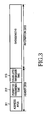
- FIG. 3 is a diagram illustrating a structure of a data frame transmitted when a local wireless communication is performed according to a preferred embodiment of the present invention.
- the structure of a wireless frame according to the present invention will be described with reference to FIG. 3.
- the frame includes a header part 310 and an information part 320.
- the header part 310 includes an address area 311, a permitted transmission time area 312, and an accumulated transmission time are 313.
- the address area 311 is an area contains an address of the next wireless terminal determined by the schedule map as shown in Table 1.
- a time period for which the frame is transmitted is contained in the permitted transmission time area 312, and the frame is transmitted for the time period given.
- time periods, for which the frame including data to be transmitted has been transmitted in one beacon period are accumulated and recorded.
- the accumulated transmission time may be calculated by accumulating the permitted transmission time of a corresponding terminal in advance and inserting the accumulated time into the header when data is to be transmitted by the corresponding terminal.
- Table 1 The frame structure will be described with reference to Table 1.
- the frame structure is as shown Table 2. Also, when a wireless terminal, which will currently transmit data, is the fourth wireless terminal 150, the frame structure is as shown Table 3.
- the third wireless terminal 2 2 data The second wireless terminal 1 6 data
- the wireless terminal that is scheduled to transmit data designates an address of a wireless terminal in the next turn in the header in order to indicate the next wireless terminal. Further, time data to be transmitted by the wireless terminal transmitting the data is contained in the header, and accumulated time information is recorded in the last part of the header. The data stream is segmented into data corresponding to the permitted transmission time assigned to the wireless terminal, and the data is then transmitted.
- transmitting the accumulated time information as described above causes a circulation period of data transmission to be easily calculated through a modulo calculation.
- the total accumulated transmission time may change.
- the next wireless terminal changes the accumulated transmission time to a value according to the schedule map to transmit the changed value. Data transmission is not actually performed, but the accumulated transmission time is determined by the schedule map.
- all peripheral wireless terminals actually calculate the total accumulated transmission time when performing transmission and transmit the 5 calculated time. Further, all wireless terminals can detect a wireless terminal which does not have data to transmit. Therefore, a transmission time value of a corresponding wireless terminal may be added to an accumulated value, and a modulo calculation is then performed at a point in time at which data transmission by the last wireless terminal in the schedule map has been completed.
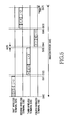
- FIG. 4 is a timing chart of a beacon period according to a preferred embodiment of the present invention. Each timing period of the beacon period according to the present invention will be described with reference to FIG. 4.
- the start of the beacon period may be reported to other wireless terminals by transmitting a beacon header 401.
- the wireless terminals examines the beacon period more than once and determines a point in time at which the beacon header 401 is detected as a starting time point of one period.
- Connection request slots 402 which are used when other wireless terminals request a new connection, are provided after the beacon header 401.
- a wireless terminal which does not perform a wireless communication, may perform a connection request during the connection request slots 402 after an ending time point of the beacon header 401.
- the main wireless terminal When the connection request exists as described above, the main wireless terminal generates a schedule map including a corresponding wireless terminal to transmit the generated schedule map to other wireless terminals.
- each wireless terminal sequentially transmits data according to a sequence set in the schedule map.
- Reference numerals 411 to 41N correspond to intervals in which the data is sequentially transmitted. The intervals will be described with reference to Table 1.
- the first wireless terminal 120 transmits data in the first transmission interval 411
- the third wireless terminal 140 transmits data in the second transmission interval 412. Since each interval is a time period set according to the schedule map, each interval has a time interval different from each other. Further, since each wireless terminal is spaced a predetermined interval from other wireless terminals, including the main wireless terminal 110, and the data transmission is performed through a wireless channel, each wireless terminal has an idle time for detecting a transmission completion time point of each data.
- Reference numeral 420 in FIG. 2 represents such an idle time.
- the idle time may be set by negotiation between the main wireless terminal and other wireless terminals, or may be a predetermined time period.
- each wireless terminal existing on the schedule map transmits the data according to the sequence of the schedule map.
- the wireless terminal transmitting the data designates another wireless terminal in the address area 311 of the header 310, which will transmit data in the next data transmission interval.
- a wireless terminal awaiting data transmission examines the address area in which a wireless terminal for transmitting the next data is designated. As a result of the examination, when the wireless terminal is selected as a wireless terminal which will transmit the data, the wireless terminal transmits the data in the next data transmission interval.
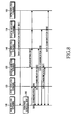
- FIG. 5 is a timing chart when a wireless terminal transmits data according to a preferred embodiment of the present invention. The timing in which the wireless terminal transmits the data according to a schedule map of the present invention will be described with reference to FIG. 5.
- FIG. 5 considers only data transmission without showing the aforementioned beacon header and the connection request slots in FIG. 4.
- FIG. 5 is an example of a case in which the data is transmitted according to the schedule map as shown in Table 1.
- the first wireless terminal 120 which will first transmit data, starts to transmit one frame at a time point 500.
- '2' is recorded in the permitted transmission time area 312 of the header 310 as shown in Table 1, and '2', which is the time accumulated up to the current time point, is recorded in the accumulated transmission time area 313 of the header 310.
- the header 310 is then transmitted.
- the data stream is segmented into data which can be transmitted for two seconds, and the segmented data is inserted into the information area 320 and transmitted. Such a transmission continues up to a time point 501 according to the schedule map.
- the third wireless terminal 140 When the data transmission by the first wireless terminal 120 has been completed at the time point 501, all wireless terminals do not transmit data for the idle time. This is for clarifying a boundary between a collision of data and the data transmission. Accordingly, the third wireless terminal 140, the next wireless terminal, inserts data of '4, 3, and 5' into the header as described above, and inserts data segmented into data which can be transmitted for three seconds to generate one frame. Then, the third wireless terminal 140 transmits the generated frame from a time point 502, at which a preset idle time has passed, to a time point 503. When an idle time such as the reference numeral 420 passes, the fourth wireless terminal 150 generates a frame in the same manner and transmits the generated frame from a time point 504 to a time point 505.
- the second wireless terminal 130 transmits a frame from a time point 506 to a time point 507 in the same manner. In this way, a time for which all of the beacon header 401,the connection request slots 402, and the data transmission intervals are performed becomes one beacon period.
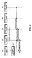
- FIG. 6 is a flow chart of a signal and data between wireless terminals when data communication is performed according to an embodiment of the present invention. A case in which the data transmission is performed between each wireless terminal and the main wireless terminal 110 according to the present invention will be described with reference to FIG. 6.
- the data transmission to the main wireless terminal 110 is formed as shown in Table 1, the data transmission is requested in a sequence of the first wireless terminal 120, the third wireless terminal 140, the fourth wireless terminal 150, and the second wireless terminal 130.
- the data transmission request by each wireless terminal may be performed in the connection request slots 402 of one beacon period, but the data transmission request signal is received in different beacon period in most cases.
- FIG. 6 a description will be given on the assumption that all data transmission requests are performed in the connection request slots 402 in one beacon period for convenience of description. Further, it is assumed that each wireless terminal transmits the data transmission request signal according to the sequence as shown in Table 1.
- the first wireless terminal 120 transmits the data transmission request signal to the main wireless terminal 110 in step 601.
- the main wireless terminal 110 negotiates with the first wireless terminal 120 during the time required for communication. Through such a negotiation, the main wireless terminal 110 may generate a schedule map.
- the third wireless terminal 140 performs a data transmission request in step 603, and the main wireless terminal 110 negotiates with the third wireless terminal 140 during a time period required for data communication similarly to a case of the first wireless terminal 120.
- the main wireless terminal 110 includes the time period negotiated with the third wireless terminal 140 in a data transmission time and generates a new schedule map. Such a process is applied to both the data transmission request performed by the fourth wireless terminal 150 in step 605 and the data transmission request performed by the second wireless terminal 130 in step 607.
- the main wireless terminal 110 can generate the schedule map at the point in time at which the negotiation according to each connection request has been completed.
- the main wireless terminal 110 performs the negotiation according to the connection request, and generates only a resultant according to the negotiation. Then, the main wireless terminal 110 can generate the schedule map as shown in Table 1 at a point in time at which all connection requests have been completed. As described above, the schedule map may be updated whenever the data transmission request exists from each wireless terminal.
- FIG. 6 shows a process in which the schedule map is generated at a time in step 609.
- the main wireless terminal 110 broadcasts information of the schedule map generated in step 609 so that all wireless terminals can receive the information in step 611. Then, each wireless terminal receives and stores the information, and can determine its own data transmission time point and a relation before or after the data transmission. Also, each wireless terminal can determine an entire beacon period. When a time period for which data can be transmitted is determined, each wireless terminal performs data communication according to the schedule map. That is, the first wireless terminal 120 generates a frame, which will be transmitted for a time period assigned to the first wireless terminal 120, in step 613, and transmits the generated frame to the main wireless terminal 110. The transmitted frame is generated in the same way as that shown in FIG. 3, and is then transmitted.
- the third wireless terminal 140 which is next in turn to transmit data, performs data communication with the main wireless terminal 110.
- each wireless terminal performs data communication with the main wireless terminal 110 in the same manner.
- the case described in FIG. 6 is a case in which every wireless terminal has data to be transmitted. However, since data traffic is actually burst when generated, there may occur a case in which data to be transmitted does not exist even if there is a data transmission interval in the beacon period, which is reserved for data transmission by a specific terminal. Hereinafter, a process in which data are transmitted in such a case will be described with reference to FIG. 7.
- FIG. 7 is a timing chart of data transmission according to another embodiment of the present invention, in which a specific wireless terminal has no data to be transmitted at its own data transmission time point.
- the first wireless terminal 120 generates a frame 710 including data which will be transmitted to the main wireless terminal 110, and transmits the generated frame.
- an address of a wireless terminal, which will transmit data in the next data transmission interval is contained a header and transmitted.
- the first wireless terminal 120 completes the transmission at a time point 701.
- the third wireless terminal 140, the next wireless terminal has no data to be transmitted, the third wireless terminal 140 does not transmit data.
- the fourth wireless terminal 150 the next wireless terminal after the third wireless terminal 140, further waits a preset idle time. That is, the fourth wireless terminal 150, which has a transmission sequence next to the third wireless terminal 140, waits a time period twice as long as a preset idle time.
- the fourth wireless terminal 150 performs a transmission of a frame. Accordingly, when the frame is not detected after a time point 702, the fourth wireless terminal 150 further waits a preset idle time. Even after the waiting, when a transmission of a frame is not detected, the fourth wireless terminal 150 recognizes that the third wireless terminal 140 has no data to be transmitted, generates a frame 712 including data to be transmitted, and transmits the generated frame from a time point 703 to a time point 705. Then, the second wireless terminal 130 generates a frame 714 including data to transmit the generated frame in the same way as that described above.
- the fourth wireless terminal 150 does not transmit any frame. Then, the second wireless terminal 130 waits for duration of three times as long as a preset idle time, and generates a frame including data to be transmitted, and transmits the generated frame. Through such a method, when data to be transmitted does not exist, the next wireless terminal can automatically generate a frame to transmit the generated frame without adding a separate header.
- each peripheral wireless terminal has no data to be transmitted for a permitted transmission time.
- the first wireless terminal 120 must transmit two second of data as shown in FIG. 7.
- data transmission will be completed before the time point 701 in FIG. 7.
- the third wireless terminal 140 which will perform the next data transmission, has data to be transmitted, an idle time passes after one second, and then data transmission does not occur, the third wireless terminal 140 transmits the data.
- the fourth wireless terminal 150 starts data transmission. In this way, the data transmission time is modified within a time period set in advance and data can be transmitted.
- a new wireless terminal may request communication. That is, there may occur a case in which data transmission is requested through the connection request slot as shown in FIG. 4. Such a case will be described with reference to FIG. 8.
- FIG. 8 is a flow chart of a signal and a frame transmitted when a new wireless terminal requests data transmission according to another embodiment of the present invention.
- the new wireless terminal detects the beacon period as describe above and requests the data communication through the connection request slots existing in one beacon period. That is, when a beacon header ends and when a point in time at which the connection request slots can be transmitted arrives, the fifth wireless terminal 160, which is to newly perform communication, transmits a signal for requesting data communication in step 801. Then, the main wireless terminal 110 determines a time period for which data will be transmitted through a negotiation with the fifth wireless terminal 160. Then, the main wireless terminal 110 generates a new schedule map in step 802. The schedule map as shown in Table 1 is updated as shown in Table 4 below. Transmission sequence Address of wireless terminal Permitted transmission time (PTT) Accumulated transmission time (ATT) 1 a first wireless terminal 2 2 2 a third wireless terminal 3 5 3 a fourth wireless terminal 1 6 4 a second wireless terminal 2 8 5 a fifth wireless terminal 3 11
- PTT Permitted transmission time
- ATT Accumulated transmission time
- each wireless terminal performs data communication as described above.
- the amount of data to be transmitted by a specific wireless terminal may suddenly increase. That is, there may occur a case in which data exceeding the amount of data which can be transmitted in a time period negotiated in advance must be continuously transmitted.
- the wireless terminal performs a new negotiation and must receive a time period for which it can transmit this additional data. In such a case, it is necessary to update the schedule map.
- such a case will be described with reference to FIG. 9.
- FIG. 9 is a signal flow diagram of a signal and traffic after the negotiation for changing an established time period according to another embodiment of the present invention.
- FIG. 9 illustrates an example in which the established time period changes when communication is performed according to the schedule map in Table 1.
- the negotiation for changing the established time period can be performed in a transmission interval, in which each wireless terminal itself transmits traffic, without a separate channel.
- the fourth wireless terminal 150 When the established time period must change, the fourth wireless terminal 150 generates a negotiation request signal at its own traffic transmission point in time to transmit the generated signal to the main wireless terminal 110.
- the fourth wireless terminal 150 has a transmission point in time at which the fourth wireless terminal 150 transmits traffic data, but the fourth wireless terminal 150 does not transmit the data but requests a negotiation for changing a transmission time.
- the fourth wireless terminal 150 requests a negotiation and performs a negotiation with the main wireless terminal 110 for changing the established time period.
- the main wireless terminal 110 updates the schedule map according to received information. Further, when the update of the schedule map has been completed, the main wireless terminal 110 broadcasts the updated schedule map to all wireless terminals in step 903. Accordingly, all wireless terminals store the updated schedule map.
- An application point in time of the schedule map is generally from the next beacon period. However, the schedule map can be applied from a current beacon period.
- the embodiment in FIG. 9 shows an example in which the schedule map is applied from the next beacon period. It is considered that the fourth wireless terminal 150 has completed a frame transmission in step 901, and the second wireless terminal 130, the next wireless terminal, transmits its data in step 904 after receiving a broadcasting signal.
- the main wireless terminal 110 broadcasts the beacon header 401. Further, when time periods of the connection request slots 402 pass after the broadcasting of the beacon header 401 has been completed, the first wireless terminal 120 performs a transmission again. Herein, the first wireless terminal 120 performs the transmission according to the schedule map broadcasted in step 903.
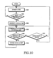
- FIG. 10 is a flowchart of a local communication by the main wireless terminal according to an embodiment of the present invention. Hereinafter, a control flow performed by the main wireless terminal 110 according to the present invention will be described with reference to FIG. 10.
- the main wireless terminal 110 maintains a standby state in step 1000.
- the standby state is a process of examining whether or not connection requests of other wireless terminals exist. For example, a time period for examining whether or not a connection request of a wireless terminal, which has not performed communication, exists through the connection request slots 402 after the beacon header has been transmitted can occur during the standby state.
- the main wireless terminal 110 examines whether or not data communication must be performed in step 1002.
- the main wireless terminal 110 determines whether or not a connection request from a predetermined wireless terminal exists in the connection request slots 402. From the result of the determination, when the connection request exists and the data communication is required, step 1004 is performed.
- the main wireless terminal 110 generates a schedule map in step 1004. Such a schedule map is generated in the same form as that in Table 1.
- the main wireless terminal 110 performs communication according to the generated schedule map in step 1006. Performing the communication according to the schedule map as described above represents a process in which communication is performed in the same manner as that in FIGs. 4 to 7.
- the main wireless terminal 110 determines whether or not it is necessary to change the schedule map in step 1008 while performing the communication according to the schedule map.
- the determination of whether or not it is necessary to change the schedule map represents an determination of whether or not the change of the data transmission time is required as described in FIG. 9.
- step 1010 is performed, otherwise, step 1012 is performed.
- the main wireless terminal 110 negotiates with a wireless terminal requesting a negotiation for the data transmission time in step 1010, and updates the schedule map according to the result of the negotiation.
- step 1006 is performed.
- step 1008 when it is not necessary to change the schedule map, the main wireless terminal 110 determines whether or not the communication with all wireless terminals is ended in step 1012. As a result of the determination in step 1012, when the communication with all wireless terminals ends, step 1000 is performed, and the main wireless terminal 110 maintains the standby state. In contrast, when the communication with all wireless terminals is not ended, step 1006 is performed. The main wireless terminal 110 then performs communication according to the schedule map.
- FIG. 11 is a flowchart of a local wireless communication by a peripheral wireless terminal according to an embodiment of the present invention.
- a control process when the peripheral wireless terminal performs the local wireless communication will be described in detail with reference to FIG. 11.
- the peripheral wireless terminal maintains a standby state in step 1100.
- the standby state represents a standby state different from that in FIG. 10. That is, the standby state in FIG. 11 represents a state during which the peripheral wireless terminal performs other operations instead of performing the wireless communication, or does not perform any operation.
- the peripheral wireless terminal determines whether or not a communication request occurs in step 1102 while performing such a standby state. As a result of the examination in step 1102, when the communication request occurs, step 1104 is performed. Otherwise, the peripheral wireless terminal continuously maintains the standby state in step 1100.
- the peripheral wireless terminal detects the beacon header 401 broadcast by the main wireless terminal 110 to examine the beacon period in step 1104. Accordingly, the peripheral wireless terminal can detect a point in time of the connection request slots 402 by examining the beacon period. When the point in time of the connection request slots 402 is detected, the peripheral wireless terminal requests a call connection to the main wireless terminal 110. Then, the peripheral wireless terminal determines data transmission time through a negotiation with the main wireless terminal 110. When the negotiation as described above has been completed, the peripheral wireless terminal receives and stores a schedule map, which is transmitted by the main wireless terminal 110, in step 1106. The peripheral wireless terminal performs communication according to the received schedule map in step 1108. Such a communication is performed in the same manner as that in FIGs. 4 to 7.
- the peripheral wireless terminal determines whether or not it is necessary to change the schedule map while performing the communication according to the schedule map in step 1108.
- the determination of whether or not it is necessary to change the schedule map represents an determination of whether or not it is necessary to change the data transmission time as described in FIG. 8.
- the peripheral wireless terminal performs a negotiation for a time change with the main wireless terminal 110 at data transmission interval of the peripheral wireless terminal in step 1112. Then, the peripheral wireless terminal receives the information of the changed 5 schedule map from the main wireless terminal 110 and stores the received information in step 1106. Then, step 1108 is performed.
- the peripheral wireless terminal determines whether or not the communication is ended in step 1114.
- the ending of the 0 communication refers to a state in which a peripheral wireless terminal performing communication for a predetermined time in one beacon period has no data to be transmitted, or the peripheral wireless terminal is to delete its own communication time in the beacon period due to other reasons.
- the peripheral wireless terminal ends the communication through a specific procedure in step 1116.
- the schedule map may automatically become modified. That is, when a transmission of a traffic does not exist for more than ten beacon periods, a corresponding peripheral wireless terminal may be deleted from the schedule map.
- step 1100 is performed without performing step 1116.
- one access point can be efficiently connected and data communication can be performed without a specific overhead when local wireless communication is performed.
- the efficient use of resources can be increased and data communication can be performed through an uncomplicated algorithm.
Applications Claiming Priority (2)
| Application Number | Priority Date | Filing Date | Title |
|---|---|---|---|
| KR2003035753 | 2003-06-03 | ||
| KR20030035753A KR100584326B1 (ko) | 2003-06-03 | 2003-06-03 | 무선 통신 시스템에서 근거리 통신 시스템 및 방법 |
Publications (2)
| Publication Number | Publication Date |
|---|---|
| EP1484873A1 true EP1484873A1 (de) | 2004-12-08 |
| EP1484873B1 EP1484873B1 (de) | 2015-08-12 |
Family
ID=33157377
Family Applications (1)
| Application Number | Title | Priority Date | Filing Date |
|---|---|---|---|
| EP04013178.1A Active EP1484873B1 (de) | 2003-06-03 | 2004-06-03 | Verfahren und System zur Durchführung schnurloser Kommunikation durch Erzeugen und Senden eines Zeitinformation und Sendeabfolge beinhaltenden Zeiteinteilungsplans |
Country Status (5)
| Country | Link |
|---|---|
| US (1) | US7643790B2 (de) |
| EP (1) | EP1484873B1 (de) |
| JP (1) | JP3962036B2 (de) |
| KR (1) | KR100584326B1 (de) |
| CN (1) | CN1607753B (de) |
Cited By (5)
| Publication number | Priority date | Publication date | Assignee | Title |
|---|---|---|---|---|
| WO2006114710A2 (en) * | 2005-02-28 | 2006-11-02 | Nokia Corporation | Discontinuous transmission/reception in a communications system |
| GB2466469A (en) * | 2008-12-22 | 2010-06-23 | Toshiba Res Europ Ltd | Sharing a common wireless communication channel |
| EP2023552A3 (de) * | 2007-08-08 | 2011-11-30 | NTT DoCoMo, Inc. | Drahtlose Kommunikationsvorrichtung und drahtloses Kommunikationsverfahren |
| US8312142B2 (en) | 2005-02-28 | 2012-11-13 | Motorola Mobility Llc | Discontinuous transmission/reception in a communications system |
| WO2014081359A1 (en) * | 2012-11-23 | 2014-05-30 | Telefonaktiebolaget L M Ericsson (Publ) | Methods and apparatuses for radio resource management |
Families Citing this family (26)
| Publication number | Priority date | Publication date | Assignee | Title |
|---|---|---|---|---|
| FR2841716B1 (fr) * | 2002-06-28 | 2005-02-04 | Thomson Licensing Sa | Procede de creation d'un nouveau reseau de communication par un terminal sans fil et terminal mettant en oeuvre le procede |
| KR20070043887A (ko) * | 2004-08-18 | 2007-04-25 | 스타카토 커뮤니케이션즈, 인코포레이티드 | 비콘 그룹 병합 |
| US8175534B2 (en) * | 2004-09-03 | 2012-05-08 | Cisco Technology, Inc. | RF-aware packet filtering in radio access networks |
| US7453885B2 (en) * | 2004-10-13 | 2008-11-18 | Rivulet Communications, Inc. | Network connection device |
| JP4398886B2 (ja) * | 2005-03-07 | 2010-01-13 | ソニー株式会社 | 通信端末装置、通信システム、通信方法、およびプログラム |
| US7826408B1 (en) * | 2005-03-14 | 2010-11-02 | Ozmo, Inc. | Apparatus and method for integrating short-range wireless personal area networks for a wireless local area network infrastructure |
| TWI276334B (en) * | 2005-09-16 | 2007-03-11 | Ind Tech Res Inst | Methods for allocating transmission bandwidths of a network |
| CN100415017C (zh) * | 2005-12-01 | 2008-08-27 | 华为技术有限公司 | 一种发言权控制方法、装置及系统 |
| JP4761365B2 (ja) * | 2005-12-28 | 2011-08-31 | Kddi株式会社 | 通信スケジューリング方法 |
| DE102006030297B4 (de) | 2006-06-30 | 2009-02-12 | Siemens Ag | Verfahren und Netzwerkknoten zur Broadcast-Übertragung von Daten mit garantierter Datenzustellung |
| KR100741383B1 (ko) * | 2006-07-28 | 2007-07-20 | 지씨티 세미컨덕터 인코포레이티드 | 무선랜 및 블루투스를 이용한 음성 데이터 전송 방법 및시스템 |
| KR101272965B1 (ko) | 2006-08-11 | 2013-06-10 | 삼성전자주식회사 | 메쉬 네트워크에서 멀티 채널을 이용한 전력 절약 방법 및장치 |
| EP2097819B1 (de) * | 2006-11-27 | 2018-07-18 | Nytell Software LLC | Anfragegesteuerte priorisierte datenstruktur |
| KR101450778B1 (ko) * | 2008-01-31 | 2014-10-14 | 삼성전자주식회사 | 제어국의 기지국 유휴 시간 설정 방법 및 그 제어국 |
| US20090249350A1 (en) * | 2008-03-31 | 2009-10-01 | John W. Senders | Resource Allocation Through Negotiation |
| US8184541B2 (en) * | 2008-07-24 | 2012-05-22 | Mediatek Inc. | Method and system for link layer scheduling in a multiple access communication system |
| CN102217275A (zh) * | 2008-11-18 | 2011-10-12 | 思达伦特网络有限责任公司 | 无线网络中的选择性寻呼 |
| US8428625B2 (en) | 2009-02-27 | 2013-04-23 | Cisco Technology, Inc. | Paging heuristics in packet based networks |
| US8861535B2 (en) | 2010-05-21 | 2014-10-14 | Cisco Technology, Inc. | Multi-tiered paging support using paging priority |
| US8537829B2 (en) | 2010-09-15 | 2013-09-17 | Cisco Technology, Inc. | Paging control in communication networks |
| US9148236B2 (en) * | 2012-09-24 | 2015-09-29 | Qualcomm Incorporated | Optimized HARQ recombining within transmission window |
| US9060347B2 (en) | 2012-11-30 | 2015-06-16 | Cisco Technology, Inc. | Subscriber-aware paging |
| WO2015121988A1 (ja) * | 2014-02-14 | 2015-08-20 | 株式会社東芝 | 通信装置、通信方法およびプログラム |
| CN106712904B (zh) * | 2016-12-27 | 2020-06-30 | 深圳市道通合创软件开发有限公司 | 数据传输的控制方法及装置、终端 |
| US11122598B2 (en) * | 2017-08-29 | 2021-09-14 | Cable Television Laboratories, Inc. | Systems and methods for latency reduction using map staggering |
| JP7126894B2 (ja) * | 2018-07-24 | 2022-08-29 | 矢崎総業株式会社 | 車載システム |
Citations (3)
| Publication number | Priority date | Publication date | Assignee | Title |
|---|---|---|---|---|
| US6198728B1 (en) | 1996-12-19 | 2001-03-06 | Phillips Electronics North America Corp. | Medium access control (MAC) protocol for wireless ATM |
| US20020105970A1 (en) | 2001-02-07 | 2002-08-08 | Xtremespectrum, Inc | System, method, and computer program product for sharing bandwidth in a wireless personal area network or a wireless local area network |
| WO2003063434A2 (en) | 2002-01-22 | 2003-07-31 | Xtremespectrum, Inc. | Method for transmission of isochronous and asynchronous data in a radio network |
Family Cites Families (3)
| Publication number | Priority date | Publication date | Assignee | Title |
|---|---|---|---|---|
| US5983073A (en) * | 1997-04-04 | 1999-11-09 | Ditzik; Richard J. | Modular notebook and PDA computer systems for personal computing and wireless communications |
| JP2001333067A (ja) | 1999-06-08 | 2001-11-30 | Sony Corp | 通信方法、通信システムおよび通信端末 |
| US20040013135A1 (en) * | 2002-07-17 | 2004-01-22 | Yoram Haddad | System and method for scheduling traffic in wireless networks |
-
2003
- 2003-06-03 KR KR20030035753A patent/KR100584326B1/ko active IP Right Grant
-
2004
- 2004-06-02 US US10/858,986 patent/US7643790B2/en active Active
- 2004-06-03 EP EP04013178.1A patent/EP1484873B1/de active Active
- 2004-06-03 JP JP2004166153A patent/JP3962036B2/ja active Active
- 2004-06-03 CN CN2004100959221A patent/CN1607753B/zh active Active
Patent Citations (3)
| Publication number | Priority date | Publication date | Assignee | Title |
|---|---|---|---|---|
| US6198728B1 (en) | 1996-12-19 | 2001-03-06 | Phillips Electronics North America Corp. | Medium access control (MAC) protocol for wireless ATM |
| US20020105970A1 (en) | 2001-02-07 | 2002-08-08 | Xtremespectrum, Inc | System, method, and computer program product for sharing bandwidth in a wireless personal area network or a wireless local area network |
| WO2003063434A2 (en) | 2002-01-22 | 2003-07-31 | Xtremespectrum, Inc. | Method for transmission of isochronous and asynchronous data in a radio network |
Non-Patent Citations (1)
| Title |
|---|
| LAN/MAN STANDARDS COMMITTEE OF THE IEEE COMPUTER SOCIETY: "Draft P 802.15.3, "Part 15.3: Wireless Medium Access Control (MAC) and Physical Layer (PHY) Specifications for High Rate Wireless Personal Area Networks (WPAN)", pg:1-xiv, chptrs: 1-5,7, 8", DRAFT P802.15.3, 17 February 2003 (2003-02-17), IEEE, 445 HOES LANE, P O BOX 1331, PISCATAWAY, NJ 08855-1331, USA, pages 107 - 228, XP002294149 * |
Cited By (11)
| Publication number | Priority date | Publication date | Assignee | Title |
|---|---|---|---|---|
| WO2006114710A2 (en) * | 2005-02-28 | 2006-11-02 | Nokia Corporation | Discontinuous transmission/reception in a communications system |
| WO2006114710A3 (en) * | 2005-02-28 | 2007-01-11 | Nokia Corp | Discontinuous transmission/reception in a communications system |
| US8312142B2 (en) | 2005-02-28 | 2012-11-13 | Motorola Mobility Llc | Discontinuous transmission/reception in a communications system |
| CN101156491B (zh) * | 2005-02-28 | 2013-07-31 | 摩托罗拉移动公司 | 通信系统中的不连续发送/接收 |
| US8572250B2 (en) | 2005-02-28 | 2013-10-29 | Motorola Mobility Llc | Discontinuous transmission/reception in a communications system |
| EP2023552A3 (de) * | 2007-08-08 | 2011-11-30 | NTT DoCoMo, Inc. | Drahtlose Kommunikationsvorrichtung und drahtloses Kommunikationsverfahren |
| US8144677B2 (en) | 2007-08-08 | 2012-03-27 | Ntt Docomo, Inc. | Wireless communication device and wireless communication method |
| GB2466469A (en) * | 2008-12-22 | 2010-06-23 | Toshiba Res Europ Ltd | Sharing a common wireless communication channel |
| WO2014081359A1 (en) * | 2012-11-23 | 2014-05-30 | Telefonaktiebolaget L M Ericsson (Publ) | Methods and apparatuses for radio resource management |
| US9717085B2 (en) | 2012-11-23 | 2017-07-25 | Telefonaktiebolaget Lm Ericsson (Publ) | Methods and apparatuses for radio resource management |
| US10064188B2 (en) | 2012-11-23 | 2018-08-28 | Telefonaktiebolaget Lm Ericsson (Publ) | Methods and apparatuses for radio resource management |
Also Published As
| Publication number | Publication date |
|---|---|
| CN1607753B (zh) | 2010-05-12 |
| JP3962036B2 (ja) | 2007-08-22 |
| JP2004364308A (ja) | 2004-12-24 |
| US7643790B2 (en) | 2010-01-05 |
| EP1484873B1 (de) | 2015-08-12 |
| US20050003856A1 (en) | 2005-01-06 |
| KR100584326B1 (ko) | 2006-05-26 |
| CN1607753A (zh) | 2005-04-20 |
| KR20040104219A (ko) | 2004-12-10 |
Similar Documents
| Publication | Publication Date | Title |
|---|---|---|
| US7643790B2 (en) | Local communication system and method in wireless communication system | |
| US6754176B1 (en) | Scheme for managing overlapping wireless computer networks | |
| CN100531076C (zh) | 通过无线电传输提供多个站间的同时通信的方法和接入点 | |
| US7593375B2 (en) | Medium access control apparatus for use in a channel overlay network | |
| KR101403342B1 (ko) | 무선 비디오 영역 네트워크를 위한 채널 설정 방법 및시스템 | |
| US7391745B2 (en) | Multiple access communication system and data transceiver | |
| CN100525226C (zh) | Wlan中的带宽准备的方法和设备 | |
| CN101707738B (zh) | 关于多播/广播服务的流处理和映射方法及装置 | |
| US8619741B2 (en) | Method and device for transmitting and receiving data in wireless network | |
| TW200814629A (en) | Wireless communication system and method | |
| US8300611B2 (en) | Method and apparatus to provide air time fairness in multiple physical transmission rate wireless systems | |
| KR100591752B1 (ko) | 독립된 복수의 전송 채널을 갖는 무선 통신 시스템 | |
| CN101207439A (zh) | 至少一个用户台和至少两个基站之间的通信方法 | |
| US20020025818A1 (en) | Method for allocating bandwidth in a wireless local area network and apparatus thereof | |
| JP2006528454A (ja) | 無線インターネット接続中継装置及びその方法 | |
| CN102349340B (zh) | 在无线网络中发送和接收数据的方法和设备 | |
| US6992996B2 (en) | Network management method, wireless transmission method and wireless transmission apparatus | |
| JP2006174263A (ja) | マルチホップ無線ネットワーク | |
| JP5292082B2 (ja) | ネットワークにおける通信方法 | |
| KR100873513B1 (ko) | 모바일 vod 시스템 및 이를 이용한 브로드캐스트스트리밍 방법 | |
| US20040202144A1 (en) | Wireless network including a time slot sorting mechanism | |
| KR20060031528A (ko) | 광대역 무선 접속 시스템에서 채널 접속 정보 송/수신 방법 | |
| KR20140112807A (ko) | 기지국 기반 다중 중계 무선 통신망을 위한 중앙 집중식 매체 접속 제어 장치 및 방법 |
Legal Events
| Date | Code | Title | Description |
|---|---|---|---|
| PUAI | Public reference made under article 153(3) epc to a published international application that has entered the european phase |
Free format text: ORIGINAL CODE: 0009012 |
|
| 17P | Request for examination filed |
Effective date: 20040603 |
|
| AK | Designated contracting states |
Kind code of ref document: A1 Designated state(s): AT BE BG CH CY CZ DE DK EE ES FI FR GB GR HU IE IT LI LU MC NL PL PT RO SE SI SK TR |
|
| AX | Request for extension of the european patent |
Extension state: AL HR LT LV MK |
|
| AKX | Designation fees paid |
Designated state(s): DE FI FR GB IT SE |
|
| 17Q | First examination report despatched |
Effective date: 20101102 |
|
| RAP1 | Party data changed (applicant data changed or rights of an application transferred) |
Owner name: SAMSUNG ELECTRONICS CO., LTD. |
|
| REG | Reference to a national code |
Ref country code: DE Ref legal event code: R079 Ref document number: 602004047643 Country of ref document: DE Free format text: PREVIOUS MAIN CLASS: H04L0012560000 Ipc: H04W0072120000 |
|
| GRAP | Despatch of communication of intention to grant a patent |
Free format text: ORIGINAL CODE: EPIDOSNIGR1 |
|
| RIC1 | Information provided on ipc code assigned before grant |
Ipc: H04W 72/12 20090101AFI20150217BHEP |
|
| INTG | Intention to grant announced |
Effective date: 20150313 |
|
| GRAS | Grant fee paid |
Free format text: ORIGINAL CODE: EPIDOSNIGR3 |
|
| GRAA | (expected) grant |
Free format text: ORIGINAL CODE: 0009210 |
|
| AK | Designated contracting states |
Kind code of ref document: B1 Designated state(s): DE FI FR GB IT SE |
|
| REG | Reference to a national code |
Ref country code: GB Ref legal event code: FG4D |
|
| REG | Reference to a national code |
Ref country code: DE Ref legal event code: R096 Ref document number: 602004047643 Country of ref document: DE |
|
| PG25 | Lapsed in a contracting state [announced via postgrant information from national office to epo] |
Ref country code: FI Free format text: LAPSE BECAUSE OF FAILURE TO SUBMIT A TRANSLATION OF THE DESCRIPTION OR TO PAY THE FEE WITHIN THE PRESCRIBED TIME-LIMIT Effective date: 20150812 |
|
| PG25 | Lapsed in a contracting state [announced via postgrant information from national office to epo] |
Ref country code: SE Free format text: LAPSE BECAUSE OF FAILURE TO SUBMIT A TRANSLATION OF THE DESCRIPTION OR TO PAY THE FEE WITHIN THE PRESCRIBED TIME-LIMIT Effective date: 20150812 |
|
| PG25 | Lapsed in a contracting state [announced via postgrant information from national office to epo] |
Ref country code: IT Free format text: LAPSE BECAUSE OF FAILURE TO SUBMIT A TRANSLATION OF THE DESCRIPTION OR TO PAY THE FEE WITHIN THE PRESCRIBED TIME-LIMIT Effective date: 20150812 |
|
| REG | Reference to a national code |
Ref country code: DE Ref legal event code: R097 Ref document number: 602004047643 Country of ref document: DE |
|
| REG | Reference to a national code |
Ref country code: FR Ref legal event code: PLFP Year of fee payment: 13 |
|
| PLBE | No opposition filed within time limit |
Free format text: ORIGINAL CODE: 0009261 |
|
| STAA | Information on the status of an ep patent application or granted ep patent |
Free format text: STATUS: NO OPPOSITION FILED WITHIN TIME LIMIT |
|
| 26N | No opposition filed |
Effective date: 20160513 |
|
| REG | Reference to a national code |
Ref country code: FR Ref legal event code: PLFP Year of fee payment: 14 |
|
| REG | Reference to a national code |
Ref country code: FR Ref legal event code: PLFP Year of fee payment: 15 |
|
| P01 | Opt-out of the competence of the unified patent court (upc) registered |
Effective date: 20230520 |
|
| PGFP | Annual fee paid to national office [announced via postgrant information from national office to epo] |
Ref country code: FR Payment date: 20230522 Year of fee payment: 20 Ref country code: DE Payment date: 20230522 Year of fee payment: 20 |
|
| PGFP | Annual fee paid to national office [announced via postgrant information from national office to epo] |
Ref country code: GB Payment date: 20230523 Year of fee payment: 20 |