EP1484655A1 - Calcul du temps de réaction d'un système de commande - Google Patents
Calcul du temps de réaction d'un système de commande Download PDFInfo
- Publication number
- EP1484655A1 EP1484655A1 EP03012937A EP03012937A EP1484655A1 EP 1484655 A1 EP1484655 A1 EP 1484655A1 EP 03012937 A EP03012937 A EP 03012937A EP 03012937 A EP03012937 A EP 03012937A EP 1484655 A1 EP1484655 A1 EP 1484655A1
- Authority
- EP
- European Patent Office
- Prior art keywords
- control system
- response time
- maximum response
- event
- components
- Prior art date
- Legal status (The legal status is an assumption and is not a legal conclusion. Google has not performed a legal analysis and makes no representation as to the accuracy of the status listed.)
- Ceased
Links
Images

Classifications
-
- G—PHYSICS
- G05—CONTROLLING; REGULATING
- G05B—CONTROL OR REGULATING SYSTEMS IN GENERAL; FUNCTIONAL ELEMENTS OF SUCH SYSTEMS; MONITORING OR TESTING ARRANGEMENTS FOR SUCH SYSTEMS OR ELEMENTS
- G05B19/00—Programme-control systems
- G05B19/02—Programme-control systems electric
- G05B19/04—Programme control other than numerical control, i.e. in sequence controllers or logic controllers
- G05B19/042—Programme control other than numerical control, i.e. in sequence controllers or logic controllers using digital processors
-
- G—PHYSICS
- G05—CONTROLLING; REGULATING
- G05B—CONTROL OR REGULATING SYSTEMS IN GENERAL; FUNCTIONAL ELEMENTS OF SUCH SYSTEMS; MONITORING OR TESTING ARRANGEMENTS FOR SUCH SYSTEMS OR ELEMENTS
- G05B2219/00—Program-control systems
- G05B2219/30—Nc systems
- G05B2219/34—Director, elements to supervisory
- G05B2219/34406—Effect of computer, communication delay in real time control
Definitions
- the invention relates to a method and an apparatus to determine at least one reaction time of a control system, as well as an input element, output element or another component of such a control system.
- DE 199 22 561 A1 describes a method for the secure transmission of data signals via a bus system in which the data signals from generated at least one sensor and at least via the bus system be transferred to an actuator. That of at least one The data signals generated by the sensors are before initiation into the bus system according to a predetermined security coding method coded. Then the encoded data signals fed into the bus system and transmitted via this. The encoded data signals are used by at least one receive the actuators and according to a specified security coding method corresponding decoding method decoded. Furthermore, an electronic surveillance system described for performing this procedure.
- the invention is based, to determine at least the task to simplify a response time of a control system.
- This task is at least determined by a procedure a response time of a control system, where the response time between the acquisition of an input signal in an input element of the control system and the output of one caused by the input signal Output signal by an output element of the control system elapsed time, which method includes the response time from each of the input element, the output element and other components of the control system Information is determined automatically.
- This task is at least performed by a device for determining a response time of a control system solved, where the response time is between the acquisition of an input signal in an input element of the control system and the output of one caused by the input signal Output signal by an output element of the control system elapsed time, the device comprising means for automatically determining the response time from each the input element, the output element and other components the information associated with the control system.
- This task is performed by an input element, an output element or other components of a control system solved, with information associated with these components, which for automatically determining at least one reaction time of the control system can be used, the response time between the detection of an input signal in the Input element of the control system and the output of a output signal caused by the input signal the output element of the control system elapsed time includes.
- the specified maximum response times of the individual components can also depend on parameter settings of the component vary.
- the single ones Numerical values are usually included in a spreadsheet program editable file accepted and added. However, this way of determining a response time is neither failsafe nor does it lead to a satisfactory one Result, since usually the maximum Response times of the individual components can be used.
- the invention offers a surprisingly simple solution, the risk of human error in assembling and Evaluate the data off and in a simpler way to get better results.
- a safety-relevant response time of a safety-related Control system determined.
- security technology is relevant between the acquisition of an input signal in an input element of the control system and the output of one caused by the input signal Output signal by an output element of the control system elapsed time relevant, d. H. in the case of security technology the time from "electrical" detection of a safety-relevant Signal request up to the "electrical" Initiation of the safety reaction, i.e. the total reaction time of the control system.
- the security profile is required additional processing times compared to the standard profile (e.g. for security-specific software drivers).
- the total response time is safety-relevant and must not be used on anyone Case exceed the so-called process fault tolerance time.
- the proposed method meets an open standard, so that e.g. B. different on a safe fieldbus Manufacturers can operate their devices and get results can be delivered with tested security.
- response times of a control system is usually different from the individual reaction times of the components of the Control system composed, contain the components information associated with the control system a further embodiment of the invention, response times or a formula for calculating response times the input element, the output element or the other Control system components.
- response times of the Components also count individual transmission times Communication routes, e.g. B. bus transmission times, cycle times of CPUs, etc. response times of the individual components, which z. B. depending on the parameter settings Component can vary, are advantageously by a formula for calculating the response time is shown.
- the maximum response time from the input element to the output element the control system is made up of the maximum response times of the individual components in the signal flow from the input element to the Output element. Because the maximum response times of each Components generally when an error occurs it is much longer than in the normal case without errors reasonable between a "maximum response time in the event of an error" and a “maximum response time in error-free Case ". Therefore, according to another advantageous Embodiment of the invention a maximum response time of the control system in the event of a fault and a maximum Response time of the control system determined in the faultless case.
- the "maximum response time in the event of an error" can z. B. be determined by a monitoring time.
- a further advantageous embodiment of the invention contain those assigned to the components of the control system Information each a maximum response time in the event of an error, a maximum response time in the error-free Case and a typical response time of the input element, the output element or the other components of the control system. Based on this information, a maximum Response time in the event of an error, a maximum response time in the faultless case and a typical response time of the Control system can be determined. It can also be application dependent any combination of different types the reaction times of the components to determine a reaction time of the control system.
- security means assigned to the stored information become.
- security means e.g. B. signatures, Encryption, defined and standardized names, etc.
- all security-relevant information can be secured become.
- the correctness and integrity of the deposited Information e.g. B. specified response times can so with or before using the information for the determination a response time checked using the security means become.
- Security aids can also include programs, program parts, Macros, functions and the like can be assigned.
- the control system 1 shows a control system in a schematic representation 1 and a device 2 for determining at least one Response time of the control system 1.
- the control system 1 has components 5 - 11, which by means of communication means 12 - 17 are connected.
- the control system 1 is u. a. around an input element 5, an output element 11 and other components 6 - 10.
- Components 5 - 11 are information 18 assigned. This information 18 is provided by the configuration system 2 to determine at least one reaction time of the Control system 1 used.
- the information can also be about the internet is available and / or on portable storage media, z. B. in the form of device master data, the configuration system be available.
- the manufacturer or the The supplier of a component 5 - 11 can be that of the respective Component-assigned information 18 on its homepage for Provide download or with the respective Component z. B. deliver a CD-ROM on which the information 18 are stored.
- the configuration system 2 is coupled with a human-machine interface 3, 4.
- the Human-machine interface 3, 4 contains a screen, Speakers, a keyboard and other input devices.
- With the reference numerals 19-24 are symbolized as circles or ellipses Response times of components 5 - 11 and the Communication means 12 - 17 designated.
- Control system 1 is a safety-related one Automation system for manufacturing and process automation.
- the control system 1 is decentralized Fieldbus technology built, e.g. B. according to the standardized Communication system PROFIBUS (IEC 61158) or the PROFIsafe profile.
- the output element 11 is a DP output module.
- the other components 6 - 10 of the control system 1 are DP slaves (components 6 or 10), DP masters (Components 7 and 9) and an F-CPU (safety-related Central unit, component 8).
- a project planning system 2 is provided, which through a human-machine interface 3, 4 can be operated by a user or information can pass on to the user.
- a response time should be from the input (failsafe sensor) to the output (failsafe actuator) can be determined over several communication links.
- the response time is that in security technology relevant time denotes that of "electrical" cognition a safety-relevant signal request up to the "electrical” Initiation of the security reaction passes.
- This response time is composed of several individual times, u. a. the bus transmission times.
- the total response time 24 of the control system 1 from the input element 5 to the output element 11 is shown in FIG. 1 as an ellipse. This Total response time 24 is made up of individual response times 19-23 together. These are u. a.
- Another Response time which contributes to the total reaction time 24, is the bus transmission time on fieldbus 13 between DP slave and DP master, symbolized by the circle 20.
- the Safety-related communication requires non-fail-safe communication additional processing times (caused e.g. by so-called F drivers).
- the entire response time 24 is safety-relevant in the example and must not under any circumstances a predefined process fault tolerance time exceed.
- the Parameterization of the system meet an open standard, so that different manufacturers on this safe fieldbus can operate their devices and the engineering system 2 results can deliver with defined security.
- the described safety-related automation system for example to control and monitor a press used. A non-restricted area of the press will be monitored by a light grid. When an intrusion occurs Item, e.g. B. a hand of a user is Light curtain generates a signal which is transmitted through the input element 5 is detected.
- a stop signal to stop the press immediately.
- a Predefined time elapses which is greater than the total Response time 24 of the control system 1 is.
- View of personal protection may, for. B. a maximum response time of 100 ms are not exceeded.
- the components 5 - 11 of the control system 1 contain in Save the relevant response times.
- the Input element 5 or the sensor contains the three reaction times "maximum response time in the event of an error", “maximum response time in case of error "and” typical response time ". These response times depend on the set parameters dependent, e.g. B. from the required security category (e.g. SIL), activation of cross-circuit monitoring, etc.
- the component manufacturer specifies all response times in Dependence on the possible parameters. So z. B. digital fail-safe input elements (so-called F-DI modules) a typical error response time of 20 ms and a maximum error reaction time of 56 ms.
- the "maximum response time in the event of an error” is equal to Monitoring time, e.g. B. the PROFIsafe timeout time (see FIG 2).
- the minimum monitoring time results from the bus parameters, the response time of the F-CPU and the acknowledgment time the fail-safe periphery.
- the "maximum response time in case of error "and the" typical reaction time " can be calculated from bus parameters today.
- the "maximum response time in the event of an error" of the F-CPU is through the cycle time monitoring and the monitoring time, z. B. the PROFIsafe timeout time.
- the "maximum response time in the faultless case” is composed of the maximum cycle time and the maximum program runtime.
- the "Typical response time” can e.g. B. from half the cycle time and the typical program duration.
- the “maximum response time in the event of an error” is equal to Monitoring time, here the PROFIsafe timeout time (see FIG 2).
- the minimum monitoring time results from the bus parameters, the response time of the F-CPU and the acknowledgment time the periphery.
- the "maximum response time in error-free Fall "and the" typical response time "can today can be calculated from bus parameters.
- the output element 11 or the actuator contains the three reaction times "maximum response time in the event of an error", “maximum Response time in case of error "and” typical reaction time ".
- These response times are of the set ones Parameters dependent, e.g. B. from SIL, activation of cross-circuit monitoring, etc. The manufacturer of the components there all response times depending on the possible parameters on.
- All saved response times also called time parameters, get defined and standardized names that decoded by the configuration system 2 and for calculation be used. These names are e.g. B. in the GSD (device master data of the component) is used.
- a CRC e.g. "F_Time_CRC” is used to check the correctness the specified time parameters.
- the project planning system 2 collects all data of the components 5 - 11 involved (including F input, F CPU, F output) and searches for component 5 - 11 with the greatest "maximum response time in the event of an error". For this component, this "maximum response time in Error case ", for all other components the "Maximum response time in case of no errors" for the calculation used.
- the configuration system 2 takes note of this according to the safety requirements (e.g. SIL 2 or SIL 3) automatically whether one or two errors are assumed got to.
- the project engineer gives the required total reaction time (F sensor to F actuator).
- the project planning system 2 determines whether this time can be achieved with the components used is. If not, a corresponding message appears. If the time is realizable, the configuration system distributes the two PROFIsafe timeout values so that the sum the total reaction time required according to the above strategy results. With the differentiated calculated values it is rather possible to prove that the required process fault tolerance time is observed.
- the "typical response time" is often of the control system 1 interesting. In general, this is the mean response time in the error-free case.
- the Determination of a "typical response time" of a safety-related Control system is a completely new approach.
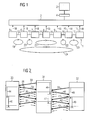
- the control system contains a fail-safe Input (F input 30), a fail-safe central unit (F-CPU 31) and a fail-safe output unit (F output 32). Communication takes place via telegrams 33 - 37 between F input 30 and F-CPU 31 or via telegrams 39 - 43 between F-CPU 31 and F-output 32.
- F-input 30, F-CPU 31 and F-output 32 communicate over a cyclic bus.
- Other components involved in communication such as z. B. DP master and DP slave are here for the sake of simplicity not shown. The repeated due to the cyclical bus Transmission of telegrams is done by the little ones Arrows 38 indicated.
- the communication flow is as follows exemplary in the communication between the F input 30 and the F-CPU 31 will be explained.
- the F-CPU 31 sends a first Telegram 33 to the F input 30.
- the F input 30 replies this first telegram 33 with a second telegram 34.
- Telegram 34 contains an acknowledgment of the first telegram 33 and possibly further information on the transfer to the F-CPU 31.
- the F-CPU monitors between F-input 30 and F-CPU 31 31 whether during the monitoring time 46 (typical value e.g.
- this telegram Acknowledgment of feedback from F input 30 is carried out and is received by the F-CPU 31.
- Telegrams 33, 35, 37 received by the F-CPU 31 immediately has acknowledged, the F-CPU 31 also acknowledges the F input 30 received telegrams 34, 36.
- the receipt of the corresponding Acknowledgment signal in a telegram 35, 37 is in the F input 30 accordingly during monitoring times 44 or 45 monitors. Communication takes place accordingly F-CPU 31 and F-edition 32.
- those of F-edition 32 telegrams 39, 41 and 43 sent immediately by the F-CPU 31 sent telegrams 40 or 42 acknowledged.
- the corresponding Monitoring times in F-CPU 31 and F output 32 are marked with the reference numerals 47 or 48 and 49.
- FIG. 3 shows a further exemplary embodiment of a method to determine a response time.
- the read ones Data becomes the one running in the spreadsheet program 63 Macro evaluated.
- they are also provided signatures of the data or macros checked, making sure that the right data were used to calculate the response times.
- the response times determined in this way are determined by suitable means 64 available to a user or other applications posed.
- the invention thus relates to a method and a device for determining at least one reaction time 24 of a control system 1 and input elements 5, output elements 11 or further components 6-10 of one Control system 1.
- a response time of a control system 1 is proposed that the response time 24 each from an input element 5, an output element 11 and other components 6 -10 of the control system 1 associated information 18 is determined automatically, the response time 24 between the detection of an input signal in the input element 5 of the control system 1 and the output of a the input signal caused by the output signal Output element 11 of the control system 1 elapsed time includes.
Landscapes
- Physics & Mathematics (AREA)
- General Physics & Mathematics (AREA)
- Engineering & Computer Science (AREA)
- Automation & Control Theory (AREA)
- Testing And Monitoring For Control Systems (AREA)
Priority Applications (1)
| Application Number | Priority Date | Filing Date | Title |
|---|---|---|---|
| EP03012937A EP1484655A1 (fr) | 2003-06-06 | 2003-06-06 | Calcul du temps de réaction d'un système de commande |
Applications Claiming Priority (1)
| Application Number | Priority Date | Filing Date | Title |
|---|---|---|---|
| EP03012937A EP1484655A1 (fr) | 2003-06-06 | 2003-06-06 | Calcul du temps de réaction d'un système de commande |
Publications (1)
| Publication Number | Publication Date |
|---|---|
| EP1484655A1 true EP1484655A1 (fr) | 2004-12-08 |
Family
ID=33155180
Family Applications (1)
| Application Number | Title | Priority Date | Filing Date |
|---|---|---|---|
| EP03012937A Ceased EP1484655A1 (fr) | 2003-06-06 | 2003-06-06 | Calcul du temps de réaction d'un système de commande |
Country Status (1)
| Country | Link |
|---|---|
| EP (1) | EP1484655A1 (fr) |
Cited By (1)
| Publication number | Priority date | Publication date | Assignee | Title |
|---|---|---|---|---|
| DE102022106058A1 (de) | 2022-03-16 | 2023-09-21 | WAGO Verwaltungsgesellschaft mit beschränkter Haftung | Bestimmung einer reaktionszeit eines eingangs oder eines ausgangs eines eingabe-/ausgabe-moduls |
Citations (4)
| Publication number | Priority date | Publication date | Assignee | Title |
|---|---|---|---|---|
| DE3640624A1 (de) * | 1986-04-30 | 1987-11-05 | Mitsubishi Electric Corp | Diagnosevorrichtung |
| EP0837394A2 (fr) * | 1996-10-18 | 1998-04-22 | Elan Schaltelemente GmbH | Système de bus à sûreté intégrée |
| EP0924585A1 (fr) * | 1997-12-19 | 1999-06-23 | Robert Bosch Gmbh | Dispositif de surveillance d'actionneur de porte de garage |
| DE10059301A1 (de) * | 2000-11-29 | 2002-06-27 | Daimler Chrysler Ag | Peripherie-Baugruppe |
-
2003
- 2003-06-06 EP EP03012937A patent/EP1484655A1/fr not_active Ceased
Patent Citations (4)
| Publication number | Priority date | Publication date | Assignee | Title |
|---|---|---|---|---|
| DE3640624A1 (de) * | 1986-04-30 | 1987-11-05 | Mitsubishi Electric Corp | Diagnosevorrichtung |
| EP0837394A2 (fr) * | 1996-10-18 | 1998-04-22 | Elan Schaltelemente GmbH | Système de bus à sûreté intégrée |
| EP0924585A1 (fr) * | 1997-12-19 | 1999-06-23 | Robert Bosch Gmbh | Dispositif de surveillance d'actionneur de porte de garage |
| DE10059301A1 (de) * | 2000-11-29 | 2002-06-27 | Daimler Chrysler Ag | Peripherie-Baugruppe |
Cited By (1)
| Publication number | Priority date | Publication date | Assignee | Title |
|---|---|---|---|---|
| DE102022106058A1 (de) | 2022-03-16 | 2023-09-21 | WAGO Verwaltungsgesellschaft mit beschränkter Haftung | Bestimmung einer reaktionszeit eines eingangs oder eines ausgangs eines eingabe-/ausgabe-moduls |
Similar Documents
| Publication | Publication Date | Title |
|---|---|---|
| EP3170287B1 (fr) | Système de commande et de transmission de données, module de passerelle, module e/a et procédé de commande de processus | |
| EP1952238B1 (fr) | Module de bus a raccorder a un systeme de bus et utilisation d'un module de bus de ce type dans un systeme de bus as-i | |
| EP0742500A2 (fr) | Fonctions de commutateur simple et à contact à sûreté intégrée avec évitement d'erreur | |
| WO2005101145A1 (fr) | Dispositif de commande de securite | |
| EP3607405B1 (fr) | Procédé de paramétrage d'un appareil de terrain et appareil de terrain paramétrable | |
| EP1296207B1 (fr) | Appareil HMI et procédé de commande d'une installation technique, système d'automatisation avec cet appareil HMI et produit de programme informatique avec un programme pour la mise en oeuvre de ce procédé dans un appareil HMI ou dans un système d'automatisation | |
| EP2246756B1 (fr) | Procédé et appareil de commande destinés à commander un composant d'automatisation industriel lié à la sécurité | |
| EP3100121B1 (fr) | Procédé et dispositif pour déconnecter en toute sécurité une charge électrique | |
| EP1043641A2 (fr) | Système d'automatisation à sécurité intrinsèque avec un processeur standard et méthode pour un système d'automatisation à sécurité intrinsèque | |
| EP3745217B1 (fr) | Dispositif de surveillance d' un système de traitement et de transmission de données. | |
| EP1748299A1 (fr) | Circuit électronique, système avec un circuit électronique et procédé pour tester un circuit électronique | |
| EP2835700B1 (fr) | Procédé de paramétrage d'un appareil de terrain | |
| EP3470937B1 (fr) | Procédé et dispositifs de surveillance du temps réactionnel d'une fonction de sécurité fournie par un système de sécurité | |
| EP3470939B1 (fr) | Procédé et système de surveillance de l'intégrité de sécurité d'une fonction de sécurité fournie par un système de sécurité | |
| EP1683016B1 (fr) | Acquisition fiable de donnees d'entree | |
| EP1484655A1 (fr) | Calcul du temps de réaction d'un système de commande | |
| EP3622403A2 (fr) | Procédé pour le contrôle automatisé assisté par ordinateur de descriptions | |
| EP1853979A1 (fr) | Commande machine comportant une fonction de securite | |
| DE102006020478A1 (de) | Verfahren zur Entwicklung sicherheitsgerichteter Softwareapplikationen | |
| DE10233879B4 (de) | Verfahren zum Steuern und Überwachen einer sicherheitskritischen Anlage, insbesondere Verkehrs-Signalanlage sowie Vorrichtung zur Durchführung des Verfahrens | |
| EP3026514B1 (fr) | Installation d'automatisation et procédé de commande externe d'un algorithme d'autocontrôle dans un dispositif de sécurité décentralisé | |
| EP4300220A1 (fr) | Procédé de communication de sécurité, dispositif de communication, système de communication de sécurité et système de commande | |
| EP3647889A1 (fr) | Contrôle de séquence de processus protégé contre les erreurs | |
| DE102021210453A1 (de) | Steuergerät, system und verfahren zum konfigurieren von geräten eines feldbusnetzwerks | |
| DE102010038484A1 (de) | Verfahren und Vorrichtung zum Steuern einer Anlage |
Legal Events
| Date | Code | Title | Description |
|---|---|---|---|
| PUAI | Public reference made under article 153(3) epc to a published international application that has entered the european phase |
Free format text: ORIGINAL CODE: 0009012 |
|
| AK | Designated contracting states |
Kind code of ref document: A1 Designated state(s): AT BE BG CH CY CZ DE DK EE ES FI FR GB GR HU IE IT LI LU MC NL PT RO SE SI SK TR |
|
| AX | Request for extension of the european patent |
Extension state: AL LT LV MK |
|
| 17P | Request for examination filed |
Effective date: 20050607 |
|
| AKX | Designation fees paid |
Designated state(s): DE FR IT |
|
| 17Q | First examination report despatched |
Effective date: 20060405 |
|
| RAP1 | Party data changed (applicant data changed or rights of an application transferred) |
Owner name: SIEMENS AKTIENGESELLSCHAFT |
|
| RAP1 | Party data changed (applicant data changed or rights of an application transferred) |
Owner name: SIEMENS AKTIENGESELLSCHAFT |
|
| STAA | Information on the status of an ep patent application or granted ep patent |
Free format text: STATUS: THE APPLICATION HAS BEEN REFUSED |
|
| 18R | Application refused |
Effective date: 20161106 |