EP1484655A1 - React time monitoring of a control system - Google Patents
React time monitoring of a control system Download PDFInfo
- Publication number
- EP1484655A1 EP1484655A1 EP03012937A EP03012937A EP1484655A1 EP 1484655 A1 EP1484655 A1 EP 1484655A1 EP 03012937 A EP03012937 A EP 03012937A EP 03012937 A EP03012937 A EP 03012937A EP 1484655 A1 EP1484655 A1 EP 1484655A1
- Authority
- EP
- European Patent Office
- Prior art keywords
- control system
- response time
- maximum response
- event
- components
- Prior art date
- Legal status (The legal status is an assumption and is not a legal conclusion. Google has not performed a legal analysis and makes no representation as to the accuracy of the status listed.)
- Ceased
Links
Images

Classifications
-
- G—PHYSICS
- G05—CONTROLLING; REGULATING
- G05B—CONTROL OR REGULATING SYSTEMS IN GENERAL; FUNCTIONAL ELEMENTS OF SUCH SYSTEMS; MONITORING OR TESTING ARRANGEMENTS FOR SUCH SYSTEMS OR ELEMENTS
- G05B19/00—Programme-control systems
- G05B19/02—Programme-control systems electric
- G05B19/04—Programme control other than numerical control, i.e. in sequence controllers or logic controllers
- G05B19/042—Programme control other than numerical control, i.e. in sequence controllers or logic controllers using digital processors
-
- G—PHYSICS
- G05—CONTROLLING; REGULATING
- G05B—CONTROL OR REGULATING SYSTEMS IN GENERAL; FUNCTIONAL ELEMENTS OF SUCH SYSTEMS; MONITORING OR TESTING ARRANGEMENTS FOR SUCH SYSTEMS OR ELEMENTS
- G05B2219/00—Program-control systems
- G05B2219/30—Nc systems
- G05B2219/34—Director, elements to supervisory
- G05B2219/34406—Effect of computer, communication delay in real time control
Definitions
- the invention relates to a method and an apparatus to determine at least one reaction time of a control system, as well as an input element, output element or another component of such a control system.
- DE 199 22 561 A1 describes a method for the secure transmission of data signals via a bus system in which the data signals from generated at least one sensor and at least via the bus system be transferred to an actuator. That of at least one The data signals generated by the sensors are before initiation into the bus system according to a predetermined security coding method coded. Then the encoded data signals fed into the bus system and transmitted via this. The encoded data signals are used by at least one receive the actuators and according to a specified security coding method corresponding decoding method decoded. Furthermore, an electronic surveillance system described for performing this procedure.
- the invention is based, to determine at least the task to simplify a response time of a control system.
- This task is at least determined by a procedure a response time of a control system, where the response time between the acquisition of an input signal in an input element of the control system and the output of one caused by the input signal Output signal by an output element of the control system elapsed time, which method includes the response time from each of the input element, the output element and other components of the control system Information is determined automatically.
- This task is at least performed by a device for determining a response time of a control system solved, where the response time is between the acquisition of an input signal in an input element of the control system and the output of one caused by the input signal Output signal by an output element of the control system elapsed time, the device comprising means for automatically determining the response time from each the input element, the output element and other components the information associated with the control system.
- This task is performed by an input element, an output element or other components of a control system solved, with information associated with these components, which for automatically determining at least one reaction time of the control system can be used, the response time between the detection of an input signal in the Input element of the control system and the output of a output signal caused by the input signal the output element of the control system elapsed time includes.
- the specified maximum response times of the individual components can also depend on parameter settings of the component vary.
- the single ones Numerical values are usually included in a spreadsheet program editable file accepted and added. However, this way of determining a response time is neither failsafe nor does it lead to a satisfactory one Result, since usually the maximum Response times of the individual components can be used.
- the invention offers a surprisingly simple solution, the risk of human error in assembling and Evaluate the data off and in a simpler way to get better results.
- a safety-relevant response time of a safety-related Control system determined.
- security technology is relevant between the acquisition of an input signal in an input element of the control system and the output of one caused by the input signal Output signal by an output element of the control system elapsed time relevant, d. H. in the case of security technology the time from "electrical" detection of a safety-relevant Signal request up to the "electrical" Initiation of the safety reaction, i.e. the total reaction time of the control system.
- the security profile is required additional processing times compared to the standard profile (e.g. for security-specific software drivers).
- the total response time is safety-relevant and must not be used on anyone Case exceed the so-called process fault tolerance time.
- the proposed method meets an open standard, so that e.g. B. different on a safe fieldbus Manufacturers can operate their devices and get results can be delivered with tested security.
- response times of a control system is usually different from the individual reaction times of the components of the Control system composed, contain the components information associated with the control system a further embodiment of the invention, response times or a formula for calculating response times the input element, the output element or the other Control system components.
- response times of the Components also count individual transmission times Communication routes, e.g. B. bus transmission times, cycle times of CPUs, etc. response times of the individual components, which z. B. depending on the parameter settings Component can vary, are advantageously by a formula for calculating the response time is shown.
- the maximum response time from the input element to the output element the control system is made up of the maximum response times of the individual components in the signal flow from the input element to the Output element. Because the maximum response times of each Components generally when an error occurs it is much longer than in the normal case without errors reasonable between a "maximum response time in the event of an error" and a “maximum response time in error-free Case ". Therefore, according to another advantageous Embodiment of the invention a maximum response time of the control system in the event of a fault and a maximum Response time of the control system determined in the faultless case.
- the "maximum response time in the event of an error" can z. B. be determined by a monitoring time.
- a further advantageous embodiment of the invention contain those assigned to the components of the control system Information each a maximum response time in the event of an error, a maximum response time in the error-free Case and a typical response time of the input element, the output element or the other components of the control system. Based on this information, a maximum Response time in the event of an error, a maximum response time in the faultless case and a typical response time of the Control system can be determined. It can also be application dependent any combination of different types the reaction times of the components to determine a reaction time of the control system.
- security means assigned to the stored information become.
- security means e.g. B. signatures, Encryption, defined and standardized names, etc.
- all security-relevant information can be secured become.
- the correctness and integrity of the deposited Information e.g. B. specified response times can so with or before using the information for the determination a response time checked using the security means become.
- Security aids can also include programs, program parts, Macros, functions and the like can be assigned.
- the control system 1 shows a control system in a schematic representation 1 and a device 2 for determining at least one Response time of the control system 1.
- the control system 1 has components 5 - 11, which by means of communication means 12 - 17 are connected.
- the control system 1 is u. a. around an input element 5, an output element 11 and other components 6 - 10.
- Components 5 - 11 are information 18 assigned. This information 18 is provided by the configuration system 2 to determine at least one reaction time of the Control system 1 used.
- the information can also be about the internet is available and / or on portable storage media, z. B. in the form of device master data, the configuration system be available.
- the manufacturer or the The supplier of a component 5 - 11 can be that of the respective Component-assigned information 18 on its homepage for Provide download or with the respective Component z. B. deliver a CD-ROM on which the information 18 are stored.
- the configuration system 2 is coupled with a human-machine interface 3, 4.
- the Human-machine interface 3, 4 contains a screen, Speakers, a keyboard and other input devices.
- With the reference numerals 19-24 are symbolized as circles or ellipses Response times of components 5 - 11 and the Communication means 12 - 17 designated.
- Control system 1 is a safety-related one Automation system for manufacturing and process automation.
- the control system 1 is decentralized Fieldbus technology built, e.g. B. according to the standardized Communication system PROFIBUS (IEC 61158) or the PROFIsafe profile.
- the output element 11 is a DP output module.
- the other components 6 - 10 of the control system 1 are DP slaves (components 6 or 10), DP masters (Components 7 and 9) and an F-CPU (safety-related Central unit, component 8).
- a project planning system 2 is provided, which through a human-machine interface 3, 4 can be operated by a user or information can pass on to the user.
- a response time should be from the input (failsafe sensor) to the output (failsafe actuator) can be determined over several communication links.
- the response time is that in security technology relevant time denotes that of "electrical" cognition a safety-relevant signal request up to the "electrical” Initiation of the security reaction passes.
- This response time is composed of several individual times, u. a. the bus transmission times.
- the total response time 24 of the control system 1 from the input element 5 to the output element 11 is shown in FIG. 1 as an ellipse. This Total response time 24 is made up of individual response times 19-23 together. These are u. a.
- Another Response time which contributes to the total reaction time 24, is the bus transmission time on fieldbus 13 between DP slave and DP master, symbolized by the circle 20.
- the Safety-related communication requires non-fail-safe communication additional processing times (caused e.g. by so-called F drivers).
- the entire response time 24 is safety-relevant in the example and must not under any circumstances a predefined process fault tolerance time exceed.
- the Parameterization of the system meet an open standard, so that different manufacturers on this safe fieldbus can operate their devices and the engineering system 2 results can deliver with defined security.
- the described safety-related automation system for example to control and monitor a press used. A non-restricted area of the press will be monitored by a light grid. When an intrusion occurs Item, e.g. B. a hand of a user is Light curtain generates a signal which is transmitted through the input element 5 is detected.
- a stop signal to stop the press immediately.
- a Predefined time elapses which is greater than the total Response time 24 of the control system 1 is.
- View of personal protection may, for. B. a maximum response time of 100 ms are not exceeded.
- the components 5 - 11 of the control system 1 contain in Save the relevant response times.
- the Input element 5 or the sensor contains the three reaction times "maximum response time in the event of an error", “maximum response time in case of error "and” typical response time ". These response times depend on the set parameters dependent, e.g. B. from the required security category (e.g. SIL), activation of cross-circuit monitoring, etc.
- the component manufacturer specifies all response times in Dependence on the possible parameters. So z. B. digital fail-safe input elements (so-called F-DI modules) a typical error response time of 20 ms and a maximum error reaction time of 56 ms.
- the "maximum response time in the event of an error” is equal to Monitoring time, e.g. B. the PROFIsafe timeout time (see FIG 2).
- the minimum monitoring time results from the bus parameters, the response time of the F-CPU and the acknowledgment time the fail-safe periphery.
- the "maximum response time in case of error "and the" typical reaction time " can be calculated from bus parameters today.
- the "maximum response time in the event of an error" of the F-CPU is through the cycle time monitoring and the monitoring time, z. B. the PROFIsafe timeout time.
- the "maximum response time in the faultless case” is composed of the maximum cycle time and the maximum program runtime.
- the "Typical response time” can e.g. B. from half the cycle time and the typical program duration.
- the “maximum response time in the event of an error” is equal to Monitoring time, here the PROFIsafe timeout time (see FIG 2).
- the minimum monitoring time results from the bus parameters, the response time of the F-CPU and the acknowledgment time the periphery.
- the "maximum response time in error-free Fall "and the" typical response time "can today can be calculated from bus parameters.
- the output element 11 or the actuator contains the three reaction times "maximum response time in the event of an error", “maximum Response time in case of error "and” typical reaction time ".
- These response times are of the set ones Parameters dependent, e.g. B. from SIL, activation of cross-circuit monitoring, etc. The manufacturer of the components there all response times depending on the possible parameters on.
- All saved response times also called time parameters, get defined and standardized names that decoded by the configuration system 2 and for calculation be used. These names are e.g. B. in the GSD (device master data of the component) is used.
- a CRC e.g. "F_Time_CRC” is used to check the correctness the specified time parameters.
- the project planning system 2 collects all data of the components 5 - 11 involved (including F input, F CPU, F output) and searches for component 5 - 11 with the greatest "maximum response time in the event of an error". For this component, this "maximum response time in Error case ", for all other components the "Maximum response time in case of no errors" for the calculation used.
- the configuration system 2 takes note of this according to the safety requirements (e.g. SIL 2 or SIL 3) automatically whether one or two errors are assumed got to.
- the project engineer gives the required total reaction time (F sensor to F actuator).
- the project planning system 2 determines whether this time can be achieved with the components used is. If not, a corresponding message appears. If the time is realizable, the configuration system distributes the two PROFIsafe timeout values so that the sum the total reaction time required according to the above strategy results. With the differentiated calculated values it is rather possible to prove that the required process fault tolerance time is observed.
- the "typical response time" is often of the control system 1 interesting. In general, this is the mean response time in the error-free case.
- the Determination of a "typical response time" of a safety-related Control system is a completely new approach.
- the control system contains a fail-safe Input (F input 30), a fail-safe central unit (F-CPU 31) and a fail-safe output unit (F output 32). Communication takes place via telegrams 33 - 37 between F input 30 and F-CPU 31 or via telegrams 39 - 43 between F-CPU 31 and F-output 32.
- F-input 30, F-CPU 31 and F-output 32 communicate over a cyclic bus.
- Other components involved in communication such as z. B. DP master and DP slave are here for the sake of simplicity not shown. The repeated due to the cyclical bus Transmission of telegrams is done by the little ones Arrows 38 indicated.
- the communication flow is as follows exemplary in the communication between the F input 30 and the F-CPU 31 will be explained.
- the F-CPU 31 sends a first Telegram 33 to the F input 30.
- the F input 30 replies this first telegram 33 with a second telegram 34.
- Telegram 34 contains an acknowledgment of the first telegram 33 and possibly further information on the transfer to the F-CPU 31.
- the F-CPU monitors between F-input 30 and F-CPU 31 31 whether during the monitoring time 46 (typical value e.g.
- this telegram Acknowledgment of feedback from F input 30 is carried out and is received by the F-CPU 31.
- Telegrams 33, 35, 37 received by the F-CPU 31 immediately has acknowledged, the F-CPU 31 also acknowledges the F input 30 received telegrams 34, 36.
- the receipt of the corresponding Acknowledgment signal in a telegram 35, 37 is in the F input 30 accordingly during monitoring times 44 or 45 monitors. Communication takes place accordingly F-CPU 31 and F-edition 32.
- those of F-edition 32 telegrams 39, 41 and 43 sent immediately by the F-CPU 31 sent telegrams 40 or 42 acknowledged.
- the corresponding Monitoring times in F-CPU 31 and F output 32 are marked with the reference numerals 47 or 48 and 49.
- FIG. 3 shows a further exemplary embodiment of a method to determine a response time.
- the read ones Data becomes the one running in the spreadsheet program 63 Macro evaluated.
- they are also provided signatures of the data or macros checked, making sure that the right data were used to calculate the response times.
- the response times determined in this way are determined by suitable means 64 available to a user or other applications posed.
- the invention thus relates to a method and a device for determining at least one reaction time 24 of a control system 1 and input elements 5, output elements 11 or further components 6-10 of one Control system 1.
- a response time of a control system 1 is proposed that the response time 24 each from an input element 5, an output element 11 and other components 6 -10 of the control system 1 associated information 18 is determined automatically, the response time 24 between the detection of an input signal in the input element 5 of the control system 1 and the output of a the input signal caused by the output signal Output element 11 of the control system 1 elapsed time includes.
Landscapes
- Physics & Mathematics (AREA)
- General Physics & Mathematics (AREA)
- Engineering & Computer Science (AREA)
- Automation & Control Theory (AREA)
- Testing And Monitoring For Control Systems (AREA)
Abstract
Description
Die Erfindung betrifft ein Verfahren sowie eine Vorrichtung zur Ermittlung mindestens einer Reaktionszeit eines Steuerungssystems, sowie ein Eingangselement, Ausgangselement bzw. eine weitere Komponente eines solchen Steuerungssystems.The invention relates to a method and an apparatus to determine at least one reaction time of a control system, as well as an input element, output element or another component of such a control system.
Ein solches Verfahren findet insbesondere Anwendung in industriellen Automatisierungssystemen. Die DE 199 22 561 A1 beschreibt ein Verfahren zur sicheren Übertragung von Datensignalen über ein Bussystem, bei welchem die Datensignale von zumindest einem Sensor erzeugt und über das Bussystem zu mindestens einem Aktor übertragen werden. Die von zumindest einem der Sensoren erzeugten Datensignale werden vor Einleitung in das Bussystem gemäß einem vorgegebenen Sicherheitscodierverfahren codiert. Anschließend werden die codierten Datensignale in das Bussystem eingespeist und über dieses übertragen. Die codierten Datensignale werden von zumindest einem der Aktoren empfangen und gemäß einem dem vorgegebenen Sicherheitscodierverfahren entsprechenden Decodierverfahren decodiert. Weiterhin wird ein elektronisches Überwachungssystem zum Durchführen dieses Verfahrens beschrieben.Such a method is used in particular in industrial applications Automation systems. DE 199 22 561 A1 describes a method for the secure transmission of data signals via a bus system in which the data signals from generated at least one sensor and at least via the bus system be transferred to an actuator. That of at least one The data signals generated by the sensors are before initiation into the bus system according to a predetermined security coding method coded. Then the encoded data signals fed into the bus system and transmitted via this. The encoded data signals are used by at least one receive the actuators and according to a specified security coding method corresponding decoding method decoded. Furthermore, an electronic surveillance system described for performing this procedure.
Der Erfindung liegt die Aufgabe zugrunde, die Ermittlung mindestens einer Reaktionszeit eines Steuerungssystems zu vereinfachen.The invention is based, to determine at least the task to simplify a response time of a control system.
Diese Aufgabe wird durch ein Verfahren zur Ermittlung mindestens einer Reaktionszeit eines Steuerungssystems gelöst, wobei die Reaktionszeit die zwischen dem Erfassen eines Eingangssignals in einem Eingangselement des Steuerungssystems und der Ausgabe eines durch das Eingangssignal veranlassten Ausgangssignals durch ein Ausgangselement des Steuerungssystems verstrichene Zeit umfasst, bei welchem Verfahren die Reaktionszeit aus jeweils dem Eingangselement, dem Ausgangselement und weiteren Komponenten des Steuerungssystems zugeordneten Informationen automatisch ermittelt wird.This task is at least determined by a procedure a response time of a control system, where the response time between the acquisition of an input signal in an input element of the control system and the output of one caused by the input signal Output signal by an output element of the control system elapsed time, which method includes the response time from each of the input element, the output element and other components of the control system Information is determined automatically.
Diese Aufgabe wird durch eine Vorrichtung zur Ermittlung mindestens einer Reaktionszeit eines Steuerungssystems gelöst, wobei die Reaktionszeit die zwischen dem Erfassen eines Eingangssignals in einem Eingangselement des Steuerungssystems und der Ausgabe eines durch das Eingangssignal veranlassten Ausgangssignals durch ein Ausgangselement des Steuerungssystems verstrichene Zeit umfasst, wobei die Vorrichtung Mittel zur automatischen Ermittlung der Reaktionszeit aus jeweils dem Eingangselement, dem Ausgangselement und weiteren Komponenten des Steuerungssystems zugeordneten Informationen aufweist.This task is at least performed by a device for determining a response time of a control system solved, where the response time is between the acquisition of an input signal in an input element of the control system and the output of one caused by the input signal Output signal by an output element of the control system elapsed time, the device comprising means for automatically determining the response time from each the input element, the output element and other components the information associated with the control system.
Diese Aufgabe wird durch ein Eingangselement, ein Ausgangselement bzw. weitere Komponenten eines Steuerungssystems gelöst, mit diesen Komponenten zugeordneten Informationen, welche zur automatischen Ermittlung mindestens einer Reaktionszeit des Steuerungssystems verwendbar sind, wobei die Reaktionszeit die zwischen dem Erfassen eines Eingangssignals im Eingangselement des Steuerungssystems und der Ausgabe eines durch das Eingangssignal veranlassten Ausgangssignals durch das Ausgangselement des Steuerungssystems verstrichene Zeit umfasst.This task is performed by an input element, an output element or other components of a control system solved, with information associated with these components, which for automatically determining at least one reaction time of the control system can be used, the response time between the detection of an input signal in the Input element of the control system and the output of a output signal caused by the input signal the output element of the control system elapsed time includes.
Um die Reaktionszeit eines Steuerungssystems vom Sensor bis zum Aktor zu ermitteln ist bisher das mühsame händische Zusammensammeln der in Gerätehandbüchern der einzelnen Komponenten des Steuerungssystems angegebenen maximalen Reaktionszeiten erforderlich. Die angegebenen maximalen Reaktionszeiten der einzelnen Komponenten können zudem abhängig von Parametereinstellungen der Komponente variieren. Die einzelnen Zahlenwerte werden üblicherweise in eine mit einem Tabellenkalkulationsprogramm bearbeitbare Datei übernommen und aufaddiert. Diese Art der Ermittlung einer Reaktionszeit ist jedoch weder fehlersicher noch führt sie zu einem zufriedenstellenden Ergebnis, da üblicherweise jeweils die maximalen Reaktionszeiten der einzelnen Komponenten herangezogen werden. Die Erfindung bietet eine überraschend einfache Lösung, um die Gefahr menschlichen Versagens beim Zusammenstellen und Auswerten der Daten auszuschalten und auf einfachere Weise bessere Ergebnisse zu erhalten.The response time of a control system from the sensor to To date, the tedious manual gathering has to be determined for the actuator in the manuals for the individual components maximum response times specified by the control system required. The specified maximum response times of the individual components can also depend on parameter settings of the component vary. The single ones Numerical values are usually included in a spreadsheet program editable file accepted and added. However, this way of determining a response time is neither failsafe nor does it lead to a satisfactory one Result, since usually the maximum Response times of the individual components can be used. The invention offers a surprisingly simple solution, the risk of human error in assembling and Evaluate the data off and in a simpler way to get better results.
Gemäß einer vorteilhaften Ausgestaltung der Erfindung wird eine sicherheitsrelevante Reaktionszeit eines sicherheitsgerichteten Steuerungssystems ermittelt. In der Sicherheitstechnik relevant ist die zwischen dem Erfassen eines Eingangssignals in einem Eingangselement des Steuerungssystems und der Ausgabe eines durch das Eingangssignal veranlassten Ausgangssignals durch ein Ausgangselement des Steuerungssystems verstrichene Zeit relevant, d. h. im Falle der Sicherheitstechnik die Zeit vom "elektrischen" Erkennen einer sicherheitsrelevanten Signalanforderung bis zum "elektrischen" Einleiten der Sicherheitsreaktion, also die Gesamtreaktionszeit des Steuerungssystems. Das Sicherheitsprofil benötigt gegenüber dem Standardprofil zusätzliche Bearbeitungszeiten (z. B. für sicherheitsspezifische Software-Treiber). Die Gesamtreaktionszeit ist sicherheitsrelevant und darf auf keinen Fall die sogenannte Prozessfehlertoleranzzeit überschreiten. Zudem genügt das vorgeschlagene Verfahren einem offenen Standard, so dass z. B. an einem sicheren Feldbus unterschiedlichste Hersteller ihre Geräte betreiben können und Ergebnisse mit geprüfter Sicherheit geliefert werden können.According to an advantageous embodiment of the invention a safety-relevant response time of a safety-related Control system determined. In security technology is relevant between the acquisition of an input signal in an input element of the control system and the output of one caused by the input signal Output signal by an output element of the control system elapsed time relevant, d. H. in the case of security technology the time from "electrical" detection of a safety-relevant Signal request up to the "electrical" Initiation of the safety reaction, i.e. the total reaction time of the control system. The security profile is required additional processing times compared to the standard profile (e.g. for security-specific software drivers). The total response time is safety-relevant and must not be used on anyone Case exceed the so-called process fault tolerance time. In addition, the proposed method meets an open standard, so that e.g. B. different on a safe fieldbus Manufacturers can operate their devices and get results can be delivered with tested security.
Da sich die Reaktionszeit eines Steuerungssystems üblicherweise aus den einzelnen Reaktionszeiten der Komponenten des Steuerungssystems zusammensetzt, enthalten die den Komponenten des Steuerungssystems zugeordneten Informationen gemäß einer weiteren Ausgestaltung der Erfindung jeweils Reaktionszeiten oder eine Formel zur Berechnung von Reaktionszeiten des Eingangselements, des Ausgangselements bzw. der weiteren Komponenten des Steuerungssystems. Zu den Reaktionszeiten der Komponenten zählen dabei auch Übertragungszeiten der einzelnen Kommunikationsstrecken, z. B. Busübertragungszeiten, Zykluszeiten von CPUs, usw. Reaktionszeiten der einzelnen Komponente, welche z. B. abhängig von Parametereinstellungen der Komponente variieren können, werden vorteilhafterweise durch eine Formel zur Berechnung der Reaktionszeit abgebildet.Because the response time of a control system is usually different from the individual reaction times of the components of the Control system composed, contain the components information associated with the control system a further embodiment of the invention, response times or a formula for calculating response times the input element, the output element or the other Control system components. At the response times of the Components also count individual transmission times Communication routes, e.g. B. bus transmission times, cycle times of CPUs, etc. response times of the individual components, which z. B. depending on the parameter settings Component can vary, are advantageously by a formula for calculating the response time is shown.
Die maximale Reaktionszeit vom Eingangselement zum Ausgangselement des Steuerungssystems, z. B. vom Sensor zum Aktor, setzt sich zusammen aus den maximalen Reaktionszeiten der einzelnen Komponenten im Signalfluss vom Eingangselement zum Ausgangselement. Da die maximalen Reaktionszeiten der einzelnen Komponenten im Allgemeinen bei Auftreten eines Fehlers wesentlich länger als im fehlerfreien Normalfall sind, ist es sinnvoll, zwischen einer "maximalen Reaktionszeit im Fehlerfall" und einer "maximalen Reaktionszeit im fehlerfreien Fall" zu unterscheiden. Daher wird gemäß einer weiteren vorteilhaften Ausgestaltung der Erfindung eine maximale Reaktionszeit des Steuerungssystems im Fehlerfall und eine maximale Reaktionszeit des Steuerungssystems im fehlerfreien Fall ermittelt. Die "maximale Reaktionszeit im Fehlerfall" kann z. B. durch eine Überwachungszeit bestimmt sein.The maximum response time from the input element to the output element the control system, e.g. B. from sensor to actuator, is made up of the maximum response times of the individual components in the signal flow from the input element to the Output element. Because the maximum response times of each Components generally when an error occurs it is much longer than in the normal case without errors reasonable between a "maximum response time in the event of an error" and a "maximum response time in error-free Case ". Therefore, according to another advantageous Embodiment of the invention a maximum response time of the control system in the event of a fault and a maximum Response time of the control system determined in the faultless case. The "maximum response time in the event of an error" can z. B. be determined by a monitoring time.
Zum herstellerunabhängigen Einsatz der Erfindung ist es von Vorteil, wenn gemäß einer weiteren Ausgestaltung der Erfindung die Informationen als Gerätestammdaten (= GSD) hinterlegt sind. Die Informationen können insbesondere in einer erweiterbaren Auszeichnungssprache, z. B. XML (= Extensible Markup Language) beschrieben sein, oder als Metawissen der Komponente zur Verfügung gestellt werden.For the manufacturer-independent use of the invention, it is from Advantage if according to a further embodiment of the invention the information is stored as device master data (= GSD) are. The information can be expanded in particular Markup language, e.g. B. XML (= Extensible Markup Language), or as meta knowledge of Component to be made available.
Gemäß einer weiteren vorteilhaften Ausgestaltung der Erfindung enthalten die den Komponenten des Steuerungssystems zugeordneten Informationen jeweils eine maximale Reaktionszeit im Fehlerfall, eine maximale Reaktionszeit im fehlerfreien Fall sowie eine typische Reaktionszeit des Eingangselements, des Ausgangselements bzw. der weiteren Komponenten des Steuerungssystems. Auf Basis dieser Informationen kann eine maximale Reaktionszeit im Fehlerfall, eine maximale Reaktionszeit im fehlerfreien Fall sowie eine typische Reaktionszeit des Steuerungssystem ermittelt werden. Zudem können anwendungsabhängig beliebige Kombinationen der unterschiedlichen Arten der Reaktionszeiten der Komponenten zur Ermittlung einer Reaktionszeit des Steuerungssystems herangezogen werden.According to a further advantageous embodiment of the invention contain those assigned to the components of the control system Information each a maximum response time in the event of an error, a maximum response time in the error-free Case and a typical response time of the input element, the output element or the other components of the control system. Based on this information, a maximum Response time in the event of an error, a maximum response time in the faultless case and a typical response time of the Control system can be determined. It can also be application dependent any combination of different types the reaction times of the components to determine a reaction time of the control system.
Insbesondere für sicherheitsgerichtete Anwendungen ist es vorteilhaft, wenn gemäß einer weiteren Ausgestaltung der Erfindung den hinterlegten Informationen Sicherheitsmittel zugeordnet werden. Durch die Sicherheitsmittel, z. B. Signaturen, Verschlüsselungen, definierte und standardisierte Namen, etc. können alle sicherheitsrelevanten Informationen abgesichert werden. Die Korrektheit und Unversehrtheit der hinterlegten Informationen, z. B. angegebene Reaktionszeiten, können so bei bzw. vor der Nutzung der Informationen zur Ermittlung einer Reaktionszeit anhand der Sicherheitsmittel überprüft werden. Hierdurch wird es möglich eine sicherheitsrelevante Aussage zur derart ermittelten Reaktionszeit bereitzustellen. Sicherheitsmittel können auch Programmen, Programmteilen, Makros, Funktionen und Ähnlichem zugeordnet werden.It is especially for safety-related applications advantageous if according to a further embodiment of the invention security means assigned to the stored information become. Through the security means, e.g. B. signatures, Encryption, defined and standardized names, etc. all security-relevant information can be secured become. The correctness and integrity of the deposited Information, e.g. B. specified response times can so with or before using the information for the determination a response time checked using the security means become. This makes it possible to have a safety-related one To provide information on the reaction time determined in this way. Security aids can also include programs, program parts, Macros, functions and the like can be assigned.
Bei der bisher üblichen händischen Ermittlung von Reaktionszeiten
werden die jeweiligen maximalen Reaktionszeiten der
Komponenten im Fehlerfall zur Berechnung herangezogen. Diese
werden addiert, das Ergebnis der Addition ist die Gesamtreaktionszeit.
Dies führt zu unnötig hohen Anforderungen an die
beteiligten Komponenten und ist auch aus sicherheitstechnischen
Gründen nicht erforderlich, da man bei übliche Sicherheitsanforderungen
von maximal einem Fehler (z. B. SIL 2; SIL
= Security Integrity Level) oder von maximal zwei Fehlern
(SIL 3) zu einem Zeitpunkt ausgehen muss. Es muss nach den
Sicherheitsanforderungen (z.B. gemäß IEC 61508) nicht von beliebig
vielen gleichzeitigen Fehlern ausgegangen werden, sondern
nur von zeitlich gestaffelt auftretenden Fehlern. Gemäß
einer weiteren vorteilhaften Ausgestaltung der Erfindung wird
daher zur Ermittlung einer maximalen Reaktionszeit des Steuerungssystems
im Fehlerfall bei einer durch Sicherheitsanforderungen
bestimmten Anzahl von Komponenten des Steuerungssystems
jeweils die maximale Reaktionszeit der Komponente im
Fehlerfall verwendet und bei den übrigen Komponenten jeweils
die maximale Reaktionszeit der Komponenten im fehlerfreien
Fall verwendet.With the usual manual determination of reaction times
the respective maximum response times of the
Components are used for the calculation in the event of an error. This
are added, the result of the addition is the total reaction time.
This leads to unnecessarily high demands on the
involved components and is also from safety-related
Reasons not necessary, since you have the usual security requirements
of a maximum of one fault (
Wenn ein Fehler erkannt und behoben wird, bevor ein zweiter Fehler in einer anderen Komponente auftritt und ein Fehler sich nicht auf die maximale Reaktionszeit mehrerer Komponenten auswirkt, muss bei der Berechnung der maximalen Reaktionszeit nur bei einer Komponente im Signalfluss die "maximale Reaktionszeit im Fehlerfall" angesetzt werden. Für alle anderen Komponenten kann die wesentlich kleinere "maximale Reaktionszeit im fehlerfreien Fall" angesetzt werden. Besonders vorteilhaft ist dabei, wenn gemäß einer weiteren Ausgestaltung der Erfindung zur Ermittlung einer maximalen Reaktionszeit des Steuerungssystems im Fehlerfall die maximale Reaktionszeit im Fehlerfall der Komponente mit der im Vergleich größten maximalen Reaktionszeit im Fehlerfall verwendet wird und bei den übrigen Komponenten die maximale Reaktionszeit der Komponenten im fehlerfreien Fall verwendet wird.If an error is detected and corrected before a second Failure occurs in another component and an error does not affect the maximum response time of multiple components has an impact when calculating the maximum response time the "maximum. only for one component in the signal flow Response time in the event of an error ". For all others Components can have the much smaller "maximum response time in the faultless case ". Especially It is advantageous if according to a further embodiment of the invention for determining a maximum response time of the control system in the event of a fault, the maximum response time in the event of a failure of the component with the comparison largest maximum response time in the event of an error and the maximum response time for the other components the components are used in a faultless case.
Nachfolgend wird die Erfindung anhand der in den Figuren dargestellten Ausführungsbeispiele näher beschrieben und erläutert.The invention is illustrated below with reference to the figures Exemplary embodiments described and explained in more detail.
Es zeigen:
- FIG 1
- eine schematische Darstellung eines Steuerungssystems sowie eine Vorrichtung zur Ermittlung mindestens einer Reaktionszeit des Steuerungssystems,
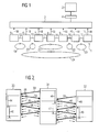
- FIG 2
- die Kommunikation zwischen Komponenten eines Steuerungssystems und
- FIG 3
- ein weiteres Ausführungsbeispiel eines Verfahrens zur Ermittlung einer Reaktionszeit.
- FIG. 1
- 1 shows a schematic representation of a control system and a device for determining at least one reaction time of the control system,
- FIG 2
- the communication between components of a control system and
- FIG 3
- another embodiment of a method for determining a response time.
FIG 1 zeigt in schematischer Darstellung ein Steuerungssystem
1 sowie eine Vorrichtung 2 zur Ermittlung mindestens einer
Reaktionszeit des Steuerungssystems 1. Das Steuerungssystem 1
weist Komponenten 5 - 11 auf, welche mittels Kommunikationsmitteln
12 - 17 verbunden sind. Bei den Komponenten 5 - 11
des Steuerungssystems 1 handelt es sich u. a. um ein Eingangselement
5, ein Ausgangselement 11 sowie weitere Komponenten
6 - 10. Den Komponenten 5 - 11 sind Informationen 18
zugeordnet. Diese Informationen 18 werden vom Projektierungssystem
2 zur Ermittlung mindestens einer Reaktionszeit des
Steuerungssystems 1 genutzt. Die Informationen 18 können in
hier nicht dargestellten Speichermitteln gespeichert sein.
Speichermittel können z. B. in die Komponenten integrierte
RAM- oder ROM-Bausteine (RAM = Random Access Memory, ROM =
Read Only Memory), transportable Speichermedien wie Memorycards
und Ähnliches sein. Die Informationen können auch über
das Internet verfügbar sein und/oder auf transportablen Speichermedien,
z. B. in Form von Geräte-Stammdaten, dem Projektierungssystem
zur Verfügung stehen. Der Hersteller bzw. der
Lieferant einer Komponente 5 - 11 kann die der jeweiligen
Komponente zugeordnete Information 18 auf seiner Homepage zum
Herunterladen zur Verfügung stellen oder mit der jeweiligen
Komponente z. B. eine CD-ROM liefern, auf welcher die Informationen
18 gespeichert sind. Das Projektierungssystem 2 ist
mit einer Mensch-Maschine-Schnittstelle 3, 4 gekoppelt. Die
Mensch-Maschine-Schnittstelle 3, 4 enthält einen Bildschirm,
Lautsprecher, eine Tastatur und weitere Eingabemittel. Mit
den Bezugszeichen 19 - 24 sind als Kreise bzw. Ellipsen symbolisierte
Reaktionszeiten der Komponenten 5 - 11 sowie der
Kommunikationsmittel 12 - 17 bezeichnet.1 shows a control system in a schematic representation
1 and a
Anhand FIG 1 soll im Folgenden ein Verfahren zur Ermittlung
mindestens einer Reaktionszeit des Steuerungssystems 1 beispielhaft
erläutert werden. Bei dem in FIG 1 dargestellten
Steuerungssystem 1 handelt es sich um ein sicherheitsgerichtetes
Automatisierungssystem für die Fertigungs- und Prozessautomatisierung.
Das Steuerungssystem 1 ist in dezentraler
Feldbustechnik aufgebaut, z. B. gemäß dem standardisierten
Kommunikationssystem PROFIBUS (IEC 61158) bzw. dem PROFIsafe-Profil.
Insofern ist das Eingangselement 5 im Ausführungsbeispiel
der FIG 1 ein DP-Eingangsmodul (DP = dezentrale Peripherie).
Das Ausgangselement 11 ist in diesem Fall ein DP-Ausgangsmodul.
Die weiteren Komponenten 6 - 10 des Steuerungssystems
1 sind DP-Slaves (Komponenten 6 bzw. 10), DP-Master
(Komponenten 7 bzw. 9) sowie eine F-CPU (sicherheitsgerichtete
Zentraleinheit, Komponente 8). Zur Projektierung
des Steuerungssystems 1 ist ein Projektierungssystem 2 vorgesehen,
welches durch eine Mensch-Maschinen-Schnittstelle 3, 4
durch einen Anwender bedient werden kann bzw. Informationen
an den Anwender weitergeben kann.A method for determination is to be described below with reference to FIG
at least one reaction time of the control system 1 as an example
are explained. In the illustrated in FIG 1
Control system 1 is a safety-related one
Automation system for manufacturing and process automation.
The control system 1 is decentralized
Fieldbus technology built, e.g. B. according to the standardized
Communication system PROFIBUS (IEC 61158) or the PROFIsafe profile.
In this respect, the input element 5 is in the exemplary embodiment
1 shows a DP input module (DP = decentralized periphery).
In this case, the output element 11 is a DP output module.
The other components 6 - 10 of the control system
1 are DP slaves (components 6 or 10), DP masters
(Components 7 and 9) and an F-CPU (safety-related
Central unit, component 8). For project planning
of the control system 1, a
Mit Hilfe des Projektierungssystems 2 soll eine Reaktionszeit
vom Eingang (Failsafe-Sensor) bis zum Ausgang (Failsafe-Aktor)
über mehrere Kommunikationsstrecken ermittelt werden.
Als Reaktionszeit wird dabei die in der Sicherheitstechnik
relevante Zeit bezeichnet, welche vom "elektrischen" Erkennen
einer sicherheitsrelevanten Signalanforderung bis zum "elektrischen"
Einleiten der Sicherheitsreaktion vergeht. Diese Reaktionszeit
setzt sich aus mehreren Einzelzeiten zusammen,
u. a. den Busübertragungszeiten. Die gesamte Reaktionszeit 24
des Steuerungssystems 1 vom Eingangselement 5 bis zum Ausgangselement
11 ist in FIG 1 als Ellipse dargestellt. Diese
gesamte Reaktionszeit 24 setzt sich aus einzelnen Reaktionszeiten
19 - 23 zusammen. Dies sind u. a. die Eingangsverzögerung
des fehlersicheren DP-Eingangsmoduls (verursacht durch
die Bearbeitungszeit) sowie der Busübertragungszeit zum DP-Slave,
hier symbolisiert durch die Ellipse 19. Eine weitere
Reaktionszeit, welche zur Gesamtreaktionszeit 24 beiträgt,
ist die Busübertragungszeit auf dem Feldbus 13 zwischen DP-Slave
und DP-Master, symbolisiert durch den Kreis 20. Die
fehlersichere Übertragung und Bearbeitung der Signale in DP-Master
und F-CPU, abhängig von der Zykluszeit der F-CPU, resultiert
in einer weiteren Reaktionszeit 21. Ebenfalls berücksichtigt
werden muss die Überwachungszeit der fehlersicheren
Kommunikation zwischen DP-Eingangsmodul und F-CPU bzw.
zwischen F-CPU und DP-Ausgangsmodul. Bis zur Ausgabe eines
Ausgangssignals durch das DP-Ausgangsmodul fallen weitere
Busübertragungszeiten 22, bzw. Bearbeitungszeiten 23 an. Die
sicherheitsgerichtete Kommunikation benötigt dabei gegenüber
einer nicht fehlersicheren Kommunikation zusätzliche Bearbeitungszeiten
(verursacht z. B. durch so genannte F-Treiber).
Die gesamte Reaktionszeit 24 ist im Beispielsfall sicherheitsrelevant
und darf auf keinen Fall eine vorgegebene Prozessfehlertoleranzzeit
überschreiten. Des Weiteren muss die
Parametrierung des Systems einem offenen Standard genügen, so
dass an diesem sicheren Feldbus unterschiedlichste Hersteller
ihre Geräte betreiben können und das Engineering System 2 Ergebnisse
mit definierter Sicherheit liefern kann. Das beschriebene
sicherheitsgerichtete Automatisierungssystem wird
beispielsweise zur Steuerung und Überwachung einer Presse
eingesetzt. Ein nicht abgeschrankter Bereich der Presse wird
dabei durch ein Lichtgitter überwacht. Bei Eindringen eines
Gegenstands, z. B. einer Hand eines Anwenders, wird durch das
Lichtgitter ein Signal erzeugt, welches durch das Eingangselement
5 erfasst wird. In diesem Fall wäre das sicherheitsrelevante
Ausgangssignal des Ausgangselements 11 ein Stoppsignal
zum sofortigen Anhalten der Presse. Zwischen Auslösen
des Lichtgitters und Anhalten der Presse darf maximal eine
zuvor definierte Zeit verstreichen, welche größer als die gesamte
Reaktionszeit 24 des Steuerungssystems 1 ist. Aus Sicht
des Personenschutzes darf z. B. eine maximale Reaktionszeit
von 100 ms nicht überschritten werden.With the help of the
Die Komponenten 5 - 11 des Steuerungssystems 1 enthalten in Speichermitteln die jeweils relevanten Reaktionszeiten. Das Eingangselement 5 bzw. der Sensor enthält die drei Reaktionszeiten "maximale Reaktionszeit im Fehlerfall", "maximale Reaktionszeit im fehlerfreien Fall" sowie "typische Reaktionszeit". Diese Reaktionszeiten sind von den eingestellten Parametern abhängig, z. B. von der geforderten Sicherheitskategorie (z. B. SIL), Aktivierung der Querschlussüberwachung, etc. Der Hersteller der Komponenten gibt alle Reaktionszeiten in Abhängigkeit von den möglichen Parametern an. So haben z. B. digitale fehlersichere Eingabeelemente (sogenannte F-DI-Baugruppen) eine typische Fehler-Reaktionszeit von 20 ms und eine maximale Fehlerreaktionszeit von 56 ms.The components 5 - 11 of the control system 1 contain in Save the relevant response times. The Input element 5 or the sensor contains the three reaction times "maximum response time in the event of an error", "maximum response time in case of error "and" typical response time ". These response times depend on the set parameters dependent, e.g. B. from the required security category (e.g. SIL), activation of cross-circuit monitoring, etc. The component manufacturer specifies all response times in Dependence on the possible parameters. So z. B. digital fail-safe input elements (so-called F-DI modules) a typical error response time of 20 ms and a maximum error reaction time of 56 ms.
Für die Kommunikation zwischen Eingangselement 5 und F-CPU ist die "maximale Reaktionszeit im Fehlerfall" gleich der Überwachungszeit, z. B. der PROFIsafe-Timeout-Zeit (siehe FIG 2). Die minimale Überwachungszeit ergibt sich aus den Bus-Parametern, der Reaktionszeit der F-CPU und der Quittierungszeit der fehlersicheren Peripherie. Die "maximale Reaktionszeit im fehlerfreien Fall" und die "typische Reaktionszeit" können heute aus Busparametern errechnet werden.For communication between input element 5 and F-CPU the "maximum response time in the event of an error" is equal to Monitoring time, e.g. B. the PROFIsafe timeout time (see FIG 2). The minimum monitoring time results from the bus parameters, the response time of the F-CPU and the acknowledgment time the fail-safe periphery. The "maximum response time in case of error "and the" typical reaction time " can be calculated from bus parameters today.
Die "maximale Reaktionszeit im Fehlerfall" der F-CPU wird durch die Zykluszeitüberwachung und die Überwachungszeit, z. B. der PROFIsafe-Timeout-Zeit, bestimmt. Die "maximale Reaktionszeit im fehlerfreien Fall" setzt sich zusammen aus der maximalen Zykluszeit und der maximalen Programmlaufzeit. Die "typische Reaktionszeit" kann z. B. aus der halben Zykluszeit und der typischen Programmlaufzeit berechnet werden.The "maximum response time in the event of an error" of the F-CPU is through the cycle time monitoring and the monitoring time, z. B. the PROFIsafe timeout time. The "maximum response time in the faultless case "is composed of the maximum cycle time and the maximum program runtime. The "Typical response time" can e.g. B. from half the cycle time and the typical program duration.
Für die Kommunikation zwischen F-CPU und Ausgangselement 11 ist die "maximale Reaktionszeit im Fehlerfall" gleich der Überwachungszeit, hier der PROFIsafe-Timeout-Zeit (siehe FIG 2). Die minimale Überwachungszeit ergibt sich aus den Bus-Parametern, der Reaktionszeit der F-CPU und der Quittierungszeit der Peripherie. Die "maximale Reaktionszeit im fehlerfreien Fall" und die "typische Reaktionszeit" können heute aus Busparametern errechnet werden.For communication between F-CPU and output element 11 the "maximum response time in the event of an error" is equal to Monitoring time, here the PROFIsafe timeout time (see FIG 2). The minimum monitoring time results from the bus parameters, the response time of the F-CPU and the acknowledgment time the periphery. The "maximum response time in error-free Fall "and the" typical response time "can today can be calculated from bus parameters.
Das Ausgangselement 11 bzw. der Aktor enthält die drei Reaktionszeiten "maximale Reaktionszeit im Fehlerfall", "maximale Reaktionszeit im fehlerfreien Fall" sowie "typische Reaktionszeit". Diese Reaktionszeiten sind von den eingestellten Parametern abhängig, z. B. vom SIL, Aktivierung der Querschlussüberwachung, etc. Der Hersteller der Komponenten gibt alle Reaktionszeiten in Abhängigkeit von den möglichen Parametern an.The output element 11 or the actuator contains the three reaction times "maximum response time in the event of an error", "maximum Response time in case of error "and" typical reaction time ". These response times are of the set ones Parameters dependent, e.g. B. from SIL, activation of cross-circuit monitoring, etc. The manufacturer of the components there all response times depending on the possible parameters on.
Alle gespeicherten Reaktionszeiten, auch Zeitparameter genannt,
erhalten definierte und standardisierte Namen, die
durch das Projektierungssystem 2 entschlüsselt und zur Berechnung
herangezogen werden. Diese Namen werden z. B. in der
GSD (Geräte-Stamm-Daten der Komponente) verwendet. Eine CRC
(z. B. "F_Time_CRC") dient zur Überprüfung der Korrektheit
der angegebenen Zeitparameter. Das Projektierungssystem 2
sammelt alle Daten der beteiligten Komponenten 5 - 11 (u. a.
F-Eingabe, F-CPU, F-Ausgabe) und sucht diejenige Komponente 5
- 11 mit der größten "maximalen Reaktionszeit im Fehlerfall".
Für diese Komponente wird diese "maximale Reaktionszeit im
Fehlerfall" übernommen, für alle anderen Komponenten wird die
"maximale Reaktionszeit im fehlerfreien Fall" für die Berechnung
herangezogen. Das Projektierungssystem 2 beachtet dabei
entsprechend der Sicherheitsvorgabe (z. B. SIL 2 oder SIL 3)
automatisch ob von einem oder zwei Fehlern ausgegangen werden
muss. Der Projekteur gibt die geforderte Gesamtreaktionszeit
(F-Sensor bis F-Aktor) vor. Das Projektierungssystem 2 ermittelt,
ob diese Zeit mit den benutzten Komponenten realisierbar
ist. Wenn nicht erscheint eine entsprechende Meldung.
Wenn die Zeit realisierbar ist verteilt das Projektierungssystem
die beiden PROFIsafe-Timeout-Werte so, dass die Summe
der Zeiten nach obiger Strategie die geforderte Gesamtreaktionszeit
ergibt. Mit den differenzierter berechneten Werten
ist eher der Nachweis möglich, dass die geforderte Prozessfehlertoleranzzeit
eingehalten wird. Optional können Vorschläge
zur Optimierung gemacht werden, z. B. wenn die Überwachungszeiten
mit einem großen Puffer gewählt wurden. Darüber
hinaus ist häufig zusätzlich die "typische Reaktionszeit"
des Steuerungssystems 1 interessant. Dies ist im Allgemeinen
die mittlere Reaktionszeit im fehlerfreien Fall. Die
Ermittlung einer "typischen Reaktionszeit" eines sicherheitsgerichteten
Steuerungssystems ist ein vollkommen neuer Ansatz.All saved response times, also called time parameters,
get defined and standardized names that
decoded by the
FIG 2 zeigt die Kommunikation zwischen Komponenten eines
Steuerungssystems. In der schematisch vereinfachten Darstellung
der FIG 2 enthält das Steuerungssystem eine fehlersichere
Eingabe (F-Eingabe 30), eine fehlersichere Zentraleinheit
(F-CPU 31) sowie eine fehlersichere Ausgabeeinheit (F-Ausgabe
32). Die Kommunikation erfolgt über Telegramme 33 - 37 zwischen
F-Eingabe 30 und F-CPU 31 bzw. über Telegramme 39 - 43
zwischen F-CPU 31 und F-Ausgabe 32. F-Eingabe 30, F-CPU 31
und F-Ausgabe 32 kommunizieren über einen zyklischen Bus.
Weitere an der Kommunikation beteiligte Komponenten, wie
z. B. DP-Master und DP-Slave sind hier der Einfachheit halber
nicht dargestellt. Die aufgrund des zyklischen Busses wiederholte
Übermittlung von Telegrammen wird durch die kleinen
Pfeile 38 angedeutet. In der schematischen Darstellung entspricht
die waagerechte Achse der räumlichen Ausdehnung des
Steuerungssystems, die senkrechte Achse hingegen dem zeitlichen
Ablauf. Der Ablauf der Kommunikation soll im Folgenden
beispielhaft an der Kommunikation zwischen der F-Eingabe 30
und der F-CPU 31 erläutert werden. Am zeitlichen Beginn der
hier dargestellten Kommunikation sendet die F-CPU 31 ein erstes
Telegramm 33 an die F-Eingabe 30. Die F-Eingabe 30 erwidert
dieses erste Telegramm 33 mit einem zweiten Telegramm
34. Das Telegramm 34 enthält eine Quittierung des ersten Telegramms
33 und eventuell weitere Informationen zur Weitergabe
an die F-CPU 31. Zur Überwachung der Kommunikationsbeziehung
zwischen F-Eingabe 30 und F-CPU 31 überwacht die F-CPU
31, ob während der Überwachungszeit 46 (typischer Wert z. B.
50 ms) nach Absenden des ersten Telegramms 33 eine dieses Telegramm
quittierende Rückmeldung der F-Eingabe 30 erfolgt und
von der F-CPU 31 empfangen wird. Ebenso wie die F-Eingabe 30
von der F-CPU 31 empfangene Telegramme 33, 35, 37 umgehend zu
quittieren hat, quittiert auch die F-CPU 31 von der F-Eingabe
30 empfangene Telegramme 34, 36. Der Empfang des entsprechenden
Quittierungssignals in einem Telegramm 35, 37 wird in der
F-Eingabe 30 entsprechend während Überwachungszeiten 44 bzw.
45 überwacht. Entsprechend erfolgt die Kommunikation zwischen
F-CPU 31 und F-Ausgabe 32. Auch werden die von F-Ausgabe 32
gesendeten Telegramme 39, 41 und 43 umgehend in von der F-CPU
31 gesendeten Telegrammen 40 bzw. 42 quittiert. Die entsprechenden
Überwachungszeiten in F-CPU 31 und F-Ausgabe 32 sind
mit den Bezugszeichen 47 bzw. 48 und 49 gekennzeichnet.2 shows the communication between components of a
Control system. In the schematically
FIG 3 zeigt ein weiteres Ausführungsbeispiel eines Verfahrens
zur Ermittlung einer Reaktionszeit. Bei dem hier dargestellten
Ausführungsbeispiel wird das Verfahren durch ein Makro
ausgeführt, welches in eine mit einem Tabellenkalkulationsprogramm
ausführbare Datei eingebettet ist. Das Auslesen von
durch ein Projektierungswerkzeug 61 bzw. durch Gerätestammdaten
60 bereitgestellten Daten über Programmierschnittstellen
62 (z. B. API = Application Programming Interface) wird mit
den Bezugszeichen 66 bzw. 65 gekennzeichnet. Die ausgelesenen
Daten werden durch das im Tabellenkalkulationsprogramm 63 ablaufende
Makro ausgewertet. Zusätzlich werden die ebenfalls
bereitgestellten Signaturen der Daten bzw. der Makros überprüft,
so dass sichergestellt wird, dass die richtigen Daten
zur Berechnung der Reaktionszeiten herangezogen wurden. Die
so ermittelten Reaktionszeiten 67 werden durch geeignete Mittel
64 einem Anwender oder weiteren Applikationen zur Verfügung
gestellt.3 shows a further exemplary embodiment of a method
to determine a response time. The one shown here
The method is exemplified by a macro
executed, which in a with a spreadsheet program
executable is embedded. Reading out
through a
Zusammengefasst betrifft die Erfindung somit ein Verfahren
sowie eine Vorrichtung zur Ermittlung mindestens einer Reaktionszeit
24 eines Steuerungssystems 1 sowie Eingangselemente
5, Ausgangselemente 11 oder weitere Komponenten 6 - 10 eines
Steuerungssystems 1. Zur Vereinfachung der Ermittlung mindestens
einer Reaktionszeit eines Steuerungssystems 1 wird vorgeschlagen,
dass die Reaktionszeit 24 aus jeweils einem Eingangselement
5, einem Ausgangselement 11 und weiteren Komponenten
6 -10 des Steuerungssystems 1 zugeordneten Informationen
18 automatisch ermittelt wird, wobei die Reaktionszeit 24
die zwischen dem Erfassen eines Eingangssignals im Eingangselement
5 des Steuerungssystems 1 und der Ausgabe eines durch
das Eingangssignal veranlassten Ausgangssignals durch das
Ausgangselement 11 des Steuerungssystems 1 verstrichene Zeit
umfasst.In summary, the invention thus relates to a method
and a device for determining at least one
Claims (19)
dadurch gekennzeichnet, dass eine sicherheitsrelevante Reaktionszeit eines sicherheitsgerichteten Steuerungssystems ermittelt wird.Method according to claim 1,
characterized in that a safety-relevant response time of a safety-related control system is determined.
dadurch gekennzeichnet, dass die Informationen (18) jeweils Reaktionszeiten oder eine Formel zur Berechnung von Reaktionszeiten des Eingangselements (5), des Ausgangselements (11) bzw. der weiteren Komponenten (6 - 10) des Steuerungssystems (1) enthalten.Method according to claim 1 or 2,
characterized in that the information (18) each contains reaction times or a formula for calculating reaction times of the input element (5), the output element (11) or the further components (6-10) of the control system (1).
dadurch gekennzeichnet, dass eine maximale Reaktionszeit des Steuerungssystems (1) im Fehlerfall und eine maximale Reaktionszeit des Steuerungssystems (1) im fehlerfreien Fall ermittelt wird.Method according to one of the preceding claims,
characterized in that a maximum response time of the control system (1) in the event of a fault and a maximum response time of the control system (1) in the event of a fault being determined.
dadurch gekennzeichnet, dass die Informationen (18) in Speichermitteln als Gerätestammdaten hinterlegt sind. Method according to one of the preceding claims,
characterized in that the information (18) is stored in storage means as device master data.
dadurch gekennzeichnet, dass die Informationen (18) jeweils eine maximale Reaktionszeit im Fehlerfall, eine maximale Reaktionszeit im fehlerfreien Fall sowie eine typische Reaktionszeit des Eingangselements (5), des Ausgangselements (11) bzw. der weiteren Komponenten (6 - 10) des Steuerungssystems (1) enthalten.Method according to one of the preceding claims,
characterized in that the information (18) each has a maximum response time in the event of an error, a maximum response time in the event of an error and a typical response time of the input element (5), the output element (11) or the further components (6-10) of the control system ( 1) included.
dadurch gekennzeichnet, dass den Informationen (18) Sicherheitsmittel zugeordnet werden.Method according to one of the preceding claims,
characterized in that the information (18) security means are assigned.
dadurch gekennzeichnet, dass zur Ermittlung einer maximalen Reaktionszeit des Steuerungssystems (1) im Fehlerfall bei einer durch Sicherheitsanforderungen bestimmten Anzahl von Komponenten (5 - 11)des Steuerungssystems (1) jeweils die maximale Reaktionszeit der Komponente im Fehlerfall verwendet wird und bei den übrigen Komponenten jeweils die maximale Reaktionszeit der Komponenten im fehlerfreien Fall verwendet wird.Method according to one of the preceding claims,
characterized in that in order to determine a maximum response time of the control system (1) in the event of a fault in the case of a number of components (5 - 11) of the control system (1) determined by safety requirements, the maximum response time of the component in the event of a fault is used and for the other components in each case the maximum response time of the components is used in the faultless case.
dadurch gekennzeichnet, dass zur Ermittlung einer maximalen Reaktionszeit des Steuerungssystems (1) im Fehlerfall die maximale Reaktionszeit im Fehlerfall der Komponente mit der im Vergleich größten maximalen Reaktionszeit im Fehlerfall verwendet wird und bei den übrigen Komponenten die maximale Reaktionszeit der Komponenten im fehlerfreien Fall verwendet wird.Method according to one of the preceding claims,
characterized in that in order to determine a maximum response time of the control system (1) in the event of a fault, the maximum response time in the event of a fault in the component is compared with the largest maximum response time in the event of a fault, and in the other components the maximum response time in the case of a fault is used for the other components.
dadurch gekennzeichnet, dass die Mittel zur automatischen Ermittlung einer sicherheitsrelevanten Reaktionszeit eines sicherheitsgerichteten Steuerungssystems vorgesehen sind.Device according to claim 10,
characterized in that the means for automatically determining a safety-relevant response time of a safety-related control system are provided.
dadurch gekennzeichnet, dass die Informationen (18) jeweils Reaktionszeiten oder eine Formel zur Berechnung von Reaktionszeiten des Eingangselements (5), des Ausgangselements (11) bzw. der weiteren Komponenten (6 - 10) des Steuerungssystems (1) enthalten.Device according to claim 10 or 11,
characterized in that the information (18) each contains reaction times or a formula for calculating reaction times of the input element (5), the output element (11) or the further components (6-10) of the control system (1).
dadurch gekennzeichnet, dass die Mittel zur automatischen Ermittlung einer maximalen Reaktionszeit des Steuerungssystems (1) im Fehlerfall und einer maximalen Reaktionszeit des Steuerungssystems (1) im fehlerfreien Fall vorgesehen sind.Device according to one of claims 10 to 12,
characterized in that the means for automatically determining a maximum response time of the control system (1) in the event of a fault and a maximum response time of the control system (1) in the event of a fault are provided.
dadurch gekennzeichnet, dass die Informationen (18) als Gerätestammdaten hinterlegt sind.Device according to one of claims 10 to 13,
characterized in that the information (18) is stored as device master data.
dadurch gekennzeichnet, dass die Informationen (18) jeweils eine maximale Reaktionszeit im Fehlerfall, eine maximale Reaktionszeit im fehlerfreien Fall sowie eine typische Reaktionszeit des Eingangselements (5), des Ausgangselements (11) bzw. der weiteren Komponenten (6 - 10) des Steuerungssystems (1) enthalten.Device according to one of claims 10 to 14,
characterized in that the information (18) each has a maximum response time in the event of an error, a maximum response time in the event of an error and a typical response time of the input element (5), the output element (11) or the further components (6-10) of the control system ( 1) included.
dadurch gekennzeichnet, dass den Informationen (18) Sicherheitsmittel zugeordnet sind.Device according to one of claims 10 to 15,
characterized in that security information is associated with the information (18).
dadurch gekennzeichnet, dass zur Ermittlung einer maximalen Reaktionszeit des Steuerungssystems (1) im Fehlerfall bei einer durch Sicherheitsanforderungen bestimmten Anzahl von Komponenten des Steuerungssystems jeweils die maximale Reaktionszeit der Komponente im Fehlerfall zur Verwendung vorgesehen ist und bei den übrigen Komponenten jeweils die maximale Reaktionszeit der Komponenten im fehlerfreien Fall zur Verwendung vorgesehen ist.Device according to one of claims 10 to 16,
characterized in that in order to determine a maximum response time of the control system (1) in the event of a fault in the case of a number of components of the control system determined by safety requirements, the maximum response time of the component is provided for use in the event of a fault and for the other components the maximum response time of the components in each case error-free case is provided for use.
dadurch gekennzeichnet, dass zur Ermittlung einer maximalen Reaktionszeit des Steuerungssystems (1) im Fehlerfall die maximale Reaktionszeit im Fehlerfall der Komponente mit der im Vergleich größten maximalen Reaktionszeit im Fehlerfall zur Verwendung vorgesehen ist und bei den übrigen Komponenten die maximale Reaktionszeit der Komponenten im fehlerfreien Fall zur Verwendung vorgesehen ist.Device according to one of claims 10 to 17,
characterized in that in order to determine a maximum response time of the control system (1) in the event of a fault, the maximum response time in the event of a fault in the component is provided for use by comparison with the largest maximum response time in the event of a fault and in the other components the maximum response time in the case of a fault is used Use is provided.
Priority Applications (1)
| Application Number | Priority Date | Filing Date | Title |
|---|---|---|---|
| EP03012937A EP1484655A1 (en) | 2003-06-06 | 2003-06-06 | React time monitoring of a control system |
Applications Claiming Priority (1)
| Application Number | Priority Date | Filing Date | Title |
|---|---|---|---|
| EP03012937A EP1484655A1 (en) | 2003-06-06 | 2003-06-06 | React time monitoring of a control system |
Publications (1)
| Publication Number | Publication Date |
|---|---|
| EP1484655A1 true EP1484655A1 (en) | 2004-12-08 |
Family
ID=33155180
Family Applications (1)
| Application Number | Title | Priority Date | Filing Date |
|---|---|---|---|
| EP03012937A Ceased EP1484655A1 (en) | 2003-06-06 | 2003-06-06 | React time monitoring of a control system |
Country Status (1)
| Country | Link |
|---|---|
| EP (1) | EP1484655A1 (en) |
Cited By (1)
| Publication number | Priority date | Publication date | Assignee | Title |
|---|---|---|---|---|
| DE102022106058A1 (en) | 2022-03-16 | 2023-09-21 | WAGO Verwaltungsgesellschaft mit beschränkter Haftung | DETERMINATION OF A RESPONSE TIME OF AN INPUT OR OUTPUT OF AN INPUT/OUTPUT MODULE |
Citations (4)
| Publication number | Priority date | Publication date | Assignee | Title |
|---|---|---|---|---|
| DE3640624A1 (en) * | 1986-04-30 | 1987-11-05 | Mitsubishi Electric Corp | DIAGNOSTIC DEVICE |
| EP0837394A2 (en) * | 1996-10-18 | 1998-04-22 | Elan Schaltelemente GmbH | Failsafe bus system |
| EP0924585A1 (en) * | 1997-12-19 | 1999-06-23 | Robert Bosch Gmbh | Surveillance device for garage door drive |
| DE10059301A1 (en) * | 2000-11-29 | 2002-06-27 | Daimler Chrysler Ag | Peripheral component for use in automation, process control, etc., is connected to a data processing unit and has an additional logic component for local control of input and output so that its response time is greatly increased |
-
2003
- 2003-06-06 EP EP03012937A patent/EP1484655A1/en not_active Ceased
Patent Citations (4)
| Publication number | Priority date | Publication date | Assignee | Title |
|---|---|---|---|---|
| DE3640624A1 (en) * | 1986-04-30 | 1987-11-05 | Mitsubishi Electric Corp | DIAGNOSTIC DEVICE |
| EP0837394A2 (en) * | 1996-10-18 | 1998-04-22 | Elan Schaltelemente GmbH | Failsafe bus system |
| EP0924585A1 (en) * | 1997-12-19 | 1999-06-23 | Robert Bosch Gmbh | Surveillance device for garage door drive |
| DE10059301A1 (en) * | 2000-11-29 | 2002-06-27 | Daimler Chrysler Ag | Peripheral component for use in automation, process control, etc., is connected to a data processing unit and has an additional logic component for local control of input and output so that its response time is greatly increased |
Cited By (1)
| Publication number | Priority date | Publication date | Assignee | Title |
|---|---|---|---|---|
| DE102022106058A1 (en) | 2022-03-16 | 2023-09-21 | WAGO Verwaltungsgesellschaft mit beschränkter Haftung | DETERMINATION OF A RESPONSE TIME OF AN INPUT OR OUTPUT OF AN INPUT/OUTPUT MODULE |
Similar Documents
| Publication | Publication Date | Title |
|---|---|---|
| DE102005055428B4 (en) | Bus module for connection to a bus system and use of such a bus module in an AS-i bus system | |
| EP3170287B1 (en) | Control and data-transfer system, gateway module, i/o module, and method for process control | |
| EP0742500A2 (en) | Fail-safe touch-switch functions and switch functions with error avoidance | |
| WO2005101145A1 (en) | Safety-oriented control system | |
| EP3607405B1 (en) | Method for parameterizing a field device, and field device that can be parameterized | |
| EP3745217B1 (en) | Device for monitoring the data processing and data transmission in a safety system | |
| EP1296207B1 (en) | HMI apparatus and method for operating a technical installation, automation system with HMI apparatus and computer program product with program for carrying out the method in a HMI apparatus or in an automation system | |
| EP2246756B1 (en) | Method and operating device for operating a security-oriented industrial automation component | |
| EP3100121B1 (en) | Method and apparatus for safely disconnecting an electrical load | |
| EP1043641A2 (en) | Failsafe automationsystem with standard-CPU and method for a failsafe automationsystem | |
| EP1748299A1 (en) | Electronic circuit, system with an electronic circuit and method to test an electronic circuit | |
| EP2835700B1 (en) | Method for adjusting the parameters of a field device | |
| EP3470937B1 (en) | Method and devices for monitoring the response time of a security function provided by a security system | |
| EP3470939B1 (en) | Method and system for monitoring the security integrity of a security function provided by a security system | |
| EP1683016B1 (en) | Secure recording of input values | |
| EP1484655A1 (en) | React time monitoring of a control system | |
| EP1853979A1 (en) | Machine controller featuring a security function | |
| DE102006020478A1 (en) | Security-related software application processing method for automation resolution, involves providing causation/execution-based programming procedure by using security-related programming system component | |
| DE10233879B4 (en) | Method for controlling and monitoring a safety-critical system, in particular a traffic signal system, and device for carrying out the method | |
| EP3026514B1 (en) | Automation system and method for external control of a self-testing algorithm in a decentralised safety device | |
| EP4300220A1 (en) | Safety communication method, communication device, safety communication system, communication system and control system | |
| EP3647889A1 (en) | Fail-safe sequence control of processes | |
| DE102021210453A1 (en) | CONTROL DEVICE, SYSTEM AND METHOD FOR CONFIGURING DEVICES OF A FIELDBUS NETWORK | |
| DE102010038484A1 (en) | Plant controlling method, involves transmitting error signal to output modules independent of fixed transmission sequence, and transferring control signal to plant in safe state based on error signal |
Legal Events
| Date | Code | Title | Description |
|---|---|---|---|
| PUAI | Public reference made under article 153(3) epc to a published international application that has entered the european phase |
Free format text: ORIGINAL CODE: 0009012 |
|
| AK | Designated contracting states |
Kind code of ref document: A1 Designated state(s): AT BE BG CH CY CZ DE DK EE ES FI FR GB GR HU IE IT LI LU MC NL PT RO SE SI SK TR |
|
| AX | Request for extension of the european patent |
Extension state: AL LT LV MK |
|
| 17P | Request for examination filed |
Effective date: 20050607 |
|
| AKX | Designation fees paid |
Designated state(s): DE FR IT |
|
| 17Q | First examination report despatched |
Effective date: 20060405 |
|
| RAP1 | Party data changed (applicant data changed or rights of an application transferred) |
Owner name: SIEMENS AKTIENGESELLSCHAFT |
|
| RAP1 | Party data changed (applicant data changed or rights of an application transferred) |
Owner name: SIEMENS AKTIENGESELLSCHAFT |
|
| STAA | Information on the status of an ep patent application or granted ep patent |
Free format text: STATUS: THE APPLICATION HAS BEEN REFUSED |
|
| 18R | Application refused |
Effective date: 20161106 |