EP1484652B1 - Hologramme généré par ordinateur et procédé pour sa fabrication - Google Patents
Hologramme généré par ordinateur et procédé pour sa fabrication Download PDFInfo
- Publication number
- EP1484652B1 EP1484652B1 EP02028431.1A EP02028431A EP1484652B1 EP 1484652 B1 EP1484652 B1 EP 1484652B1 EP 02028431 A EP02028431 A EP 02028431A EP 1484652 B1 EP1484652 B1 EP 1484652B1
- Authority
- EP
- European Patent Office
- Prior art keywords
- recording surface
- light sources
- computation
- sample light
- original
- Prior art date
- Legal status (The legal status is an assumption and is not a legal conclusion. Google has not performed a legal analysis and makes no representation as to the accuracy of the status listed.)
- Expired - Lifetime
Links
- 238000000034 method Methods 0.000 title claims description 69
- 230000008569 process Effects 0.000 title claims description 37
- 238000004519 manufacturing process Methods 0.000 title claims description 26
- 230000003287 optical effect Effects 0.000 claims description 36
- 230000007480 spreading Effects 0.000 claims description 33
- 238000003892 spreading Methods 0.000 claims description 33
- 239000011800 void material Substances 0.000 claims description 19
- 238000009826 distribution Methods 0.000 claims description 14
- 238000005520 cutting process Methods 0.000 claims description 7
- 230000006870 function Effects 0.000 description 20
- 239000000463 material Substances 0.000 description 14
- 238000010894 electron beam technology Methods 0.000 description 11
- 238000002834 transmittance Methods 0.000 description 10
- CIWBSHSKHKDKBQ-JLAZNSOCSA-N Ascorbic acid Chemical compound OC[C@H](O)[C@H]1OC(=O)C(O)=C1O CIWBSHSKHKDKBQ-JLAZNSOCSA-N 0.000 description 7
- 238000002310 reflectometry Methods 0.000 description 7
- 239000011159 matrix material Substances 0.000 description 6
- 238000012545 processing Methods 0.000 description 6
- 238000010276 construction Methods 0.000 description 5
- 238000005286 illumination Methods 0.000 description 5
- 241000282461 Canis lupus Species 0.000 description 3
- 230000015572 biosynthetic process Effects 0.000 description 3
- 230000003252 repetitive effect Effects 0.000 description 3
- 230000008859 change Effects 0.000 description 2
- 230000002265 prevention Effects 0.000 description 2
- 230000009467 reduction Effects 0.000 description 2
- 230000016776 visual perception Effects 0.000 description 2
- 208000035126 Facies Diseases 0.000 description 1
- 230000001154 acute effect Effects 0.000 description 1
- 238000004364 calculation method Methods 0.000 description 1
- 230000003915 cell function Effects 0.000 description 1
- 239000003795 chemical substances by application Substances 0.000 description 1
- 230000001427 coherent effect Effects 0.000 description 1
- 239000003086 colorant Substances 0.000 description 1
- 238000005094 computer simulation Methods 0.000 description 1
- 230000001276 controlling effect Effects 0.000 description 1
- 238000013461 design Methods 0.000 description 1
- 238000011161 development Methods 0.000 description 1
- 230000018109 developmental process Effects 0.000 description 1
- 210000000887 face Anatomy 0.000 description 1
- 230000007774 longterm Effects 0.000 description 1
- 230000004048 modification Effects 0.000 description 1
- 238000012986 modification Methods 0.000 description 1
- 208000017983 photosensitivity disease Diseases 0.000 description 1
- 231100000434 photosensitization Toxicity 0.000 description 1
- 230000001105 regulatory effect Effects 0.000 description 1
- 239000004065 semiconductor Substances 0.000 description 1
- 230000003746 surface roughness Effects 0.000 description 1
- 230000000007 visual effect Effects 0.000 description 1
Images


Classifications
-
- G—PHYSICS
- G03—PHOTOGRAPHY; CINEMATOGRAPHY; ANALOGOUS TECHNIQUES USING WAVES OTHER THAN OPTICAL WAVES; ELECTROGRAPHY; HOLOGRAPHY
- G03H—HOLOGRAPHIC PROCESSES OR APPARATUS
- G03H1/00—Holographic processes or apparatus using light, infrared or ultraviolet waves for obtaining holograms or for obtaining an image from them; Details peculiar thereto
- G03H1/04—Processes or apparatus for producing holograms
- G03H1/08—Synthesising holograms, i.e. holograms synthesized from objects or objects from holograms
- G03H1/0808—Methods of numerical synthesis, e.g. coherent ray tracing [CRT], diffraction specific
-
- G—PHYSICS
- G03—PHOTOGRAPHY; CINEMATOGRAPHY; ANALOGOUS TECHNIQUES USING WAVES OTHER THAN OPTICAL WAVES; ELECTROGRAPHY; HOLOGRAPHY
- G03H—HOLOGRAPHIC PROCESSES OR APPARATUS
- G03H1/00—Holographic processes or apparatus using light, infrared or ultraviolet waves for obtaining holograms or for obtaining an image from them; Details peculiar thereto
- G03H1/04—Processes or apparatus for producing holograms
- G03H1/08—Synthesising holograms, i.e. holograms synthesized from objects or objects from holograms
- G03H1/0841—Encoding method mapping the synthesized field into a restricted set of values representative of the modulator parameters, e.g. detour phase coding
-
- G—PHYSICS
- G03—PHOTOGRAPHY; CINEMATOGRAPHY; ANALOGOUS TECHNIQUES USING WAVES OTHER THAN OPTICAL WAVES; ELECTROGRAPHY; HOLOGRAPHY
- G03H—HOLOGRAPHIC PROCESSES OR APPARATUS
- G03H1/00—Holographic processes or apparatus using light, infrared or ultraviolet waves for obtaining holograms or for obtaining an image from them; Details peculiar thereto
- G03H1/02—Details of features involved during the holographic process; Replication of holograms without interference recording
- G03H1/0276—Replicating a master hologram without interference recording
- G03H1/028—Replicating a master hologram without interference recording by embossing
-
- G—PHYSICS
- G03—PHOTOGRAPHY; CINEMATOGRAPHY; ANALOGOUS TECHNIQUES USING WAVES OTHER THAN OPTICAL WAVES; ELECTROGRAPHY; HOLOGRAPHY
- G03H—HOLOGRAPHIC PROCESSES OR APPARATUS
- G03H1/00—Holographic processes or apparatus using light, infrared or ultraviolet waves for obtaining holograms or for obtaining an image from them; Details peculiar thereto
- G03H1/04—Processes or apparatus for producing holograms
- G03H1/08—Synthesising holograms, i.e. holograms synthesized from objects or objects from holograms
- G03H1/0891—Processes or apparatus adapted to convert digital holographic data into a hologram
-
- G—PHYSICS
- G03—PHOTOGRAPHY; CINEMATOGRAPHY; ANALOGOUS TECHNIQUES USING WAVES OTHER THAN OPTICAL WAVES; ELECTROGRAPHY; HOLOGRAPHY
- G03H—HOLOGRAPHIC PROCESSES OR APPARATUS
- G03H1/00—Holographic processes or apparatus using light, infrared or ultraviolet waves for obtaining holograms or for obtaining an image from them; Details peculiar thereto
- G03H1/26—Processes or apparatus specially adapted to produce multiple sub- holograms or to obtain images from them, e.g. multicolour technique
- G03H1/30—Processes or apparatus specially adapted to produce multiple sub- holograms or to obtain images from them, e.g. multicolour technique discrete holograms only
-
- G—PHYSICS
- G03—PHOTOGRAPHY; CINEMATOGRAPHY; ANALOGOUS TECHNIQUES USING WAVES OTHER THAN OPTICAL WAVES; ELECTROGRAPHY; HOLOGRAPHY
- G03H—HOLOGRAPHIC PROCESSES OR APPARATUS
- G03H1/00—Holographic processes or apparatus using light, infrared or ultraviolet waves for obtaining holograms or for obtaining an image from them; Details peculiar thereto
- G03H1/0005—Adaptation of holography to specific applications
- G03H1/0011—Adaptation of holography to specific applications for security or authentication
- G03H2001/0016—Covert holograms or holobjects requiring additional knowledge to be perceived, e.g. holobject reconstructed only under IR illumination
-
- G—PHYSICS
- G03—PHOTOGRAPHY; CINEMATOGRAPHY; ANALOGOUS TECHNIQUES USING WAVES OTHER THAN OPTICAL WAVES; ELECTROGRAPHY; HOLOGRAPHY
- G03H—HOLOGRAPHIC PROCESSES OR APPARATUS
- G03H1/00—Holographic processes or apparatus using light, infrared or ultraviolet waves for obtaining holograms or for obtaining an image from them; Details peculiar thereto
- G03H1/02—Details of features involved during the holographic process; Replication of holograms without interference recording
- G03H2001/0204—Object characteristics
-
- G—PHYSICS
- G03—PHOTOGRAPHY; CINEMATOGRAPHY; ANALOGOUS TECHNIQUES USING WAVES OTHER THAN OPTICAL WAVES; ELECTROGRAPHY; HOLOGRAPHY
- G03H—HOLOGRAPHIC PROCESSES OR APPARATUS
- G03H1/00—Holographic processes or apparatus using light, infrared or ultraviolet waves for obtaining holograms or for obtaining an image from them; Details peculiar thereto
- G03H1/04—Processes or apparatus for producing holograms
- G03H1/08—Synthesising holograms, i.e. holograms synthesized from objects or objects from holograms
- G03H1/0841—Encoding method mapping the synthesized field into a restricted set of values representative of the modulator parameters, e.g. detour phase coding
- G03H2001/0858—Cell encoding wherein each computed values is represented by at least two pixels of the modulator, e.g. detour phase coding
-
- G—PHYSICS
- G03—PHOTOGRAPHY; CINEMATOGRAPHY; ANALOGOUS TECHNIQUES USING WAVES OTHER THAN OPTICAL WAVES; ELECTROGRAPHY; HOLOGRAPHY
- G03H—HOLOGRAPHIC PROCESSES OR APPARATUS
- G03H1/00—Holographic processes or apparatus using light, infrared or ultraviolet waves for obtaining holograms or for obtaining an image from them; Details peculiar thereto
- G03H1/22—Processes or apparatus for obtaining an optical image from holograms
- G03H1/2202—Reconstruction geometries or arrangements
- G03H2001/2236—Details of the viewing window
- G03H2001/2242—Multiple viewing windows
-
- G—PHYSICS
- G03—PHOTOGRAPHY; CINEMATOGRAPHY; ANALOGOUS TECHNIQUES USING WAVES OTHER THAN OPTICAL WAVES; ELECTROGRAPHY; HOLOGRAPHY
- G03H—HOLOGRAPHIC PROCESSES OR APPARATUS
- G03H1/00—Holographic processes or apparatus using light, infrared or ultraviolet waves for obtaining holograms or for obtaining an image from them; Details peculiar thereto
- G03H1/22—Processes or apparatus for obtaining an optical image from holograms
- G03H1/2249—Holobject properties
- G03H2001/2252—Location of the holobject
- G03H2001/226—Virtual or real
-
- G—PHYSICS
- G03—PHOTOGRAPHY; CINEMATOGRAPHY; ANALOGOUS TECHNIQUES USING WAVES OTHER THAN OPTICAL WAVES; ELECTROGRAPHY; HOLOGRAPHY
- G03H—HOLOGRAPHIC PROCESSES OR APPARATUS
- G03H1/00—Holographic processes or apparatus using light, infrared or ultraviolet waves for obtaining holograms or for obtaining an image from them; Details peculiar thereto
- G03H1/26—Processes or apparatus specially adapted to produce multiple sub- holograms or to obtain images from them, e.g. multicolour technique
- G03H2001/2605—Arrangement of the sub-holograms, e.g. partial overlapping
-
- G—PHYSICS
- G03—PHOTOGRAPHY; CINEMATOGRAPHY; ANALOGOUS TECHNIQUES USING WAVES OTHER THAN OPTICAL WAVES; ELECTROGRAPHY; HOLOGRAPHY
- G03H—HOLOGRAPHIC PROCESSES OR APPARATUS
- G03H1/00—Holographic processes or apparatus using light, infrared or ultraviolet waves for obtaining holograms or for obtaining an image from them; Details peculiar thereto
- G03H1/26—Processes or apparatus specially adapted to produce multiple sub- holograms or to obtain images from them, e.g. multicolour technique
- G03H1/30—Processes or apparatus specially adapted to produce multiple sub- holograms or to obtain images from them, e.g. multicolour technique discrete holograms only
- G03H2001/306—Tiled identical sub-holograms
-
- G—PHYSICS
- G03—PHOTOGRAPHY; CINEMATOGRAPHY; ANALOGOUS TECHNIQUES USING WAVES OTHER THAN OPTICAL WAVES; ELECTROGRAPHY; HOLOGRAPHY
- G03H—HOLOGRAPHIC PROCESSES OR APPARATUS
- G03H2210/00—Object characteristics
- G03H2210/30—3D object
-
- G—PHYSICS
- G03—PHOTOGRAPHY; CINEMATOGRAPHY; ANALOGOUS TECHNIQUES USING WAVES OTHER THAN OPTICAL WAVES; ELECTROGRAPHY; HOLOGRAPHY
- G03H—HOLOGRAPHIC PROCESSES OR APPARATUS
- G03H2210/00—Object characteristics
- G03H2210/30—3D object
- G03H2210/32—3D+2D, i.e. composition of 3D and 2D sub-objects, e.g. scene in front of planar background
-
- G—PHYSICS
- G03—PHOTOGRAPHY; CINEMATOGRAPHY; ANALOGOUS TECHNIQUES USING WAVES OTHER THAN OPTICAL WAVES; ELECTROGRAPHY; HOLOGRAPHY
- G03H—HOLOGRAPHIC PROCESSES OR APPARATUS
- G03H2210/00—Object characteristics
- G03H2210/30—3D object
- G03H2210/36—Occluded features resolved due to parallax selectivity
-
- G—PHYSICS
- G03—PHOTOGRAPHY; CINEMATOGRAPHY; ANALOGOUS TECHNIQUES USING WAVES OTHER THAN OPTICAL WAVES; ELECTROGRAPHY; HOLOGRAPHY
- G03H—HOLOGRAPHIC PROCESSES OR APPARATUS
- G03H2210/00—Object characteristics
- G03H2210/40—Synthetic representation, i.e. digital or optical object decomposition
-
- G—PHYSICS
- G03—PHOTOGRAPHY; CINEMATOGRAPHY; ANALOGOUS TECHNIQUES USING WAVES OTHER THAN OPTICAL WAVES; ELECTROGRAPHY; HOLOGRAPHY
- G03H—HOLOGRAPHIC PROCESSES OR APPARATUS
- G03H2210/00—Object characteristics
- G03H2210/40—Synthetic representation, i.e. digital or optical object decomposition
- G03H2210/45—Representation of the decomposed object
- G03H2210/452—Representation of the decomposed object into points
-
- G—PHYSICS
- G03—PHOTOGRAPHY; CINEMATOGRAPHY; ANALOGOUS TECHNIQUES USING WAVES OTHER THAN OPTICAL WAVES; ELECTROGRAPHY; HOLOGRAPHY
- G03H—HOLOGRAPHIC PROCESSES OR APPARATUS
- G03H2210/00—Object characteristics
- G03H2210/40—Synthetic representation, i.e. digital or optical object decomposition
- G03H2210/45—Representation of the decomposed object
- G03H2210/454—Representation of the decomposed object into planes
-
- G—PHYSICS
- G03—PHOTOGRAPHY; CINEMATOGRAPHY; ANALOGOUS TECHNIQUES USING WAVES OTHER THAN OPTICAL WAVES; ELECTROGRAPHY; HOLOGRAPHY
- G03H—HOLOGRAPHIC PROCESSES OR APPARATUS
- G03H2210/00—Object characteristics
- G03H2210/50—Nature of the object
- G03H2210/52—Alphanumerical
-
- G—PHYSICS
- G03—PHOTOGRAPHY; CINEMATOGRAPHY; ANALOGOUS TECHNIQUES USING WAVES OTHER THAN OPTICAL WAVES; ELECTROGRAPHY; HOLOGRAPHY
- G03H—HOLOGRAPHIC PROCESSES OR APPARATUS
- G03H2210/00—Object characteristics
- G03H2210/50—Nature of the object
- G03H2210/55—Having particular size, e.g. irresolvable by the eye
-
- G—PHYSICS
- G03—PHOTOGRAPHY; CINEMATOGRAPHY; ANALOGOUS TECHNIQUES USING WAVES OTHER THAN OPTICAL WAVES; ELECTROGRAPHY; HOLOGRAPHY
- G03H—HOLOGRAPHIC PROCESSES OR APPARATUS
- G03H2210/00—Object characteristics
- G03H2210/50—Nature of the object
- G03H2210/56—Multiple objects, e.g. each in different environment
-
- G—PHYSICS
- G03—PHOTOGRAPHY; CINEMATOGRAPHY; ANALOGOUS TECHNIQUES USING WAVES OTHER THAN OPTICAL WAVES; ELECTROGRAPHY; HOLOGRAPHY
- G03H—HOLOGRAPHIC PROCESSES OR APPARATUS
- G03H2224/00—Writing means other than actinic light wave
- G03H2224/04—Particle beam, e.g. e-beam
-
- G—PHYSICS
- G03—PHOTOGRAPHY; CINEMATOGRAPHY; ANALOGOUS TECHNIQUES USING WAVES OTHER THAN OPTICAL WAVES; ELECTROGRAPHY; HOLOGRAPHY
- G03H—HOLOGRAPHIC PROCESSES OR APPARATUS
- G03H2240/00—Hologram nature or properties
- G03H2240/10—Physical parameter modulated by the hologram
- G03H2240/13—Amplitude and phase complex modulation
-
- G—PHYSICS
- G03—PHOTOGRAPHY; CINEMATOGRAPHY; ANALOGOUS TECHNIQUES USING WAVES OTHER THAN OPTICAL WAVES; ELECTROGRAPHY; HOLOGRAPHY
- G03H—HOLOGRAPHIC PROCESSES OR APPARATUS
- G03H2240/00—Hologram nature or properties
- G03H2240/50—Parameters or numerical values associated with holography, e.g. peel strength
- G03H2240/56—Resolution
-
- G—PHYSICS
- G03—PHOTOGRAPHY; CINEMATOGRAPHY; ANALOGOUS TECHNIQUES USING WAVES OTHER THAN OPTICAL WAVES; ELECTROGRAPHY; HOLOGRAPHY
- G03H—HOLOGRAPHIC PROCESSES OR APPARATUS
- G03H2240/00—Hologram nature or properties
- G03H2240/50—Parameters or numerical values associated with holography, e.g. peel strength
- G03H2240/62—Sampling aspect applied to sensor or display
Definitions
- the present invention relates to a hologram-recorded medium and a process for the fabrication of the same, and more particularly to a process for the fabrication of a computer-generated hologram in which an optical pattern is formed on a given recording surface by computer-aided computation and a hologram-recorded medium obtained by the same.
- holograms are obtained by recording original images on media in form of interference fringes, using optical techniques. That is, an object that forms an original image is first provided. Then, light from this object and reference light are guided through an optical system such as a lens onto a recording surface with a photosensitive agent coated thereon to form interference fringes on the recording surface.
- an optical system such as a lens onto a recording surface with a photosensitive agent coated thereon to form interference fringes on the recording surface.
- a hologram fabricated by such techniques is generally called a computer-generated hologram (CGH for short) or referred to simply as a computer hologram.
- CGH computer-generated hologram
- This computer hologram is obtained by computer simulation of a process of generation of optical interference fringes, which process is all performed through computer-aided computations.
- image data on an interference fringe pattern have been obtained by such computations, physical interference fringes are formed on an actual medium.
- a specific technique has already been put to practical use, in which image data on a computer-generated interference fringe pattern are given to an electron beam lithographic system, so that the data are scanned by electron beams on a medium thereby forming physical interference fringes on the medium.
- micro-characters by printing are now often used as anti-counterfeiting means for notes, credit cards, etc.
- the micro-characters because of being little perceivable by the naked eyes, are effective for anti-counterfeiting purposes.
- recent improvements in the performance of copiers enable general printed micro-characters to be copied with some precision. To utilize micro-characters as anti-counterfeiting means, something new is in need.
- Japanese Utility Model JP H0966 discloses a method for recording micro-characters having a maximum size of 300 ⁇ m or less in the form of a diffraction grating pattern.
- Such micro-characters recorded as the diffraction grating pattern cannot be copied on current ordinary copiers and so are very effective for prevention of counterfeiting by copiers.
- It is here understood that such recorded micro-characters of 300 ⁇ m or less are authenticated on an enlarged scale under loupes or the like because they cannot visually be perceived.
- loupes, microscopes or the like will enable any person to check the content of authenticating information recorded in the form of micro-characters.
- JP-H 11-21793 discloses an optical hologram fabrication process wherein a real original image comprising characters of normal size is recorded by optical reduction processing as a micro-character hologram pattern.
- EP-A-0 590 828 discloses a process of fabricating a computer-generated hologram having interference fringes synthesized on a given recording surface by computer-aided computation, which comprises the steps of: defining faces and edges of a cube (original object), a recording surface, and reference light, and defining a multiplicity of sample light sources on each original object and defining a multiplicity of computation points on the recording surface, whereby for each computation point, the intensity of interference waves formed by object light coming from all or some of the sample light sources and reference light is so found by computation that interference fringes having the thus found intensity distribution are formed on the recording surface as a hologram for the plurality of original images, wherein process settings are such that spatial densities of sample light sources defined on at least two different original images differ from each other.
- one object of the present invention is to provide a process for the fabrication by computation of a computer-generated hologram for an original image comprising a micro-pattern such as a micro-character pattern, wherein computation loads on computers are minimized.
- Another object of the present invention is to provide a hologram-recorded medium fabricated by such a process. This object is achieved with the features of the claims.
- the reference light beams corresponding to the 2 to K original objects may be all be the same or they may be divided into some groups.
- the virtual computer object which is recorded as CGH is also referred to simply as object or image.
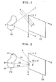
- Fig. 1 is illustrative of the principles of how to fabricate a general hologram, showing how to record an original image 10 in the form of interference fringes on a recording surface 20.
- the recording surface 20 is placed on an XY plane on the XYZ three-dimensional coordinate system defined as shown in Fig. 1 .
- an actual object or its real or virtual image is provided as the original image 10.
- Object light O emanating from an arbitrary point P on the original image 10 propagates toward the whole recording surface 20.
- the recording surface 20 is irradiated with reference light R, so that interference fringes of object light O and reference light R are recorded on the recording surface 20.
- the original image 10, recording surface 20 and reference light R are each defined in the form of data on a computer, so that the intensity of interference waves at each position on the recording surface 20 can be calculated.
- the original image 10 is processed as a set of N sample light sources P1, P2, P3, ..., Pi, ..., PN, as shown in Fig. 2 , and that object light beams 01, 02, 03, ..., Oi, ..., ON from the respective sample sources propagate toward a computation point Q(x, y) when reference light R is directed toward the computation point Q(x, y).
- the intensity of amplitude at the computation point Q(x, y) of interference waves created by interference of these N object light beams O1 to ON and reference light R is found by computation.
- point light sources capable of transmitting object light as spherical waves are used as the sample light sources P, it is acceptable to use line sources or minute surface illuminants as the sample light sources.
- the sample light sources used do not necessarily emit light by themselves, and so may have the property of producing object light by reflection of some illumination light.
- the original image 10 is defined as an assembly of many polygons and for each polygon, its direction or reflectivity on a three-dimensional space is defined. Accordingly, given a certain illumination environment, object light may be defined as reflected light from an arbitrary point on the original image 10.
- a multiplicity of computation points consistent with the necessary resolution are defined on the recording surface 20, and the intensity of amplitude for each computation point is computed so that the intensity distribution of interference waves is obtained on the recording surface 20.
- a matrix array of numerous computation points Q(x, y) are defined on the recording surface 20 at a pitch of 0.6 ⁇ m in the X-axis direction and at a pitch of 0.25 ⁇ m in the Y-axis direction, and for each computation point the intensity value of amplitude of interference fringes is found.
- the pitch of computation points defined on the recording surface 20 is not always limited to the aforesaid value; to record interference fringes for obtaining a reconstructed hologram image, however, it is required that a multiplicity of computation points be defined at a fine pitch consistent with the wavelength range of light.
- the intensity distribution of an interference fringe pattern consistent with the resolution of the array of computation points (0.6 ⁇ m in the X-axis direction and 0.25 ⁇ m in the Y-axis direction in the aforesaid embodiment) is obtained on the recording surface 20, and such an intensity distribution is represented as image data on a two-dimensional plane.
- physical interference fringes physical light-and-shade or embossed patterns
- a computer-generated hologram can be fabricated.
- an electron beam lithographic system that is widely used in applications where mask patterns for semiconductor integrated circuits are written, and functions to perform electron beam scanning with high precision. Therefore, if image data indicative of the intensity distribution of interference waves found by computation are provided to an electron beam lithographic system for electron beam scanning, it is then possible to write an interference fringe pattern consistent with that intensity distribution.
- a common electron beam lithographic system has only a function of controlling writing/non-writing, thereby writing a binary image; that is, it is general to subject the intensity distribution found by computation to binary operation and give the resultant binary image data to the electron beam lithographic system.
- the given intensity value of amplitude is defined by the aforesaid computation on each computation point Q(x, y).
- a given threshold value e.g., an average of all intensity values of amplitude distributed over the recording surface 20
- a pixel value "1” is imparted to a computation point having an intensity value of greater than that threshold value while a pixel value "0" to a computation point having an intensity value of less than that threshold value
- each computation point Q(x, y) is converted to a pixel D(x, y) having a pixel value "1" or "0”
- a binary image comprising a set of a multiplicity of pixels D(x, y) is obtained. If the binary image data are given to the electron beam lithographic system for image writing, then the interference fringes can be written in the form of a physical binary image.
- an embossed medium that is a master hologram medium is fabricated on the basis of the thus physically written interference fringes, and embossment is carried out using that embossed hologram medium.
- embossed hologram medium it is possible to mass-fabricate holograms wherein the interference fringes are formed on the surface in the form of a pit-and-projection structure.
- the present invention has been figured out as means for using computation to form an original image comprising micro-characters in the form of a hologram pattern.
- hologram-recorded media having original images of visually unperceivable size recorded therein provide very effective anti-counterfeiting means for notes or credit cards.
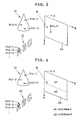
- Fig. 3 is in principle illustrative of how to record on a recording surface 20 an original image 11 of visually perceivable normal size and an original image 12 comprising micro-characters of visually unperceivable size, using a computer hologram methodology.
- the original images 11 and 12 are drawn with much the same size. In actual applications, however, both the original images are considerably different from each other.
- the original image 11 is a simple conical 3D image that is about 10 mm in height and of visually fully perceivable size.
- the original image 12 is a plane image comprising three micro-characters "ABC" (instead of which it is acceptable to use a 3D thick image), each having a height of about 200 ⁇ m.
- micro-characters having a maximum size of 300 ⁇ m or less are visually unperceivable, and the characters forming the original image 12 cannot visually be perceived as any significant characters.
- both the visually viewable original image 11 and the visually unviewable original image 12 are recorded on the recording surface 20 in the form of a hologram pattern, they can then be reconstructed in a 3D image form.
- the original image 12 is in itself a set of planar characters, yet it is reconstructed in the form of characters aligned on a three-dimensional space. Accordingly, if such a hologram pattern on the recording surface 20 is formed on a physical recording medium for use as an anti-counterfeiting seal for credit cards or the like, simple authentication can be carried out by visual observation of the original image 11. Whenever necessary, more precise authentication may be carried out by observation of the original image 12 under a loupe or a microscope.
- a fundamental idea of the present invention is that for each original image, the spatial density of the sample light sources to be defined varies in such a way that the sample light sources are recorded at a high density for an original image (e.g., original image 12) that must be recorded with high resolution, and the sample light sources are recorded at a low density for an original image (e.g., original image 11) that should not be recorded with high resolution.
- Fig. 3 shows an arrangement wherein three sample light sources P11-1, P11-2 and P11-3 are defined on the original image 11. Needless to say, much more sample light sources must actually be arranged to record the conical original image 11.
- sample light sources P12-1, P12-2, ... are defined at a higher spatial density.
- sample light sources For the original image 11 that is a conical image of about 10 mm in height, it is only needed to define sample light sources with the resolution necessary for visual perception of such a 3D image pattern.
- the original image 12 that comprises micro-characters having a maximum size of about 200 ⁇ m, however, it is necessary to define sample light sources with resolution high enough for visual perception of fine shape information upon observation under magnifying means such as a loupe.
- the present invention comprises that when sample light sources are defined on a plurality of original images 11 and 12, their spatial density is varied for each original image. While this embodiment has been described with reference to two original images 11 and 12, it is understood that the same holds true for an arrangement where three or more original images are used.
- the present invention comprises the following features: When 2 to K original images are recorded on a single recording surface 20, the spatial densities of the sample light sources defined on at least two different original images should be set in such a way as to differ from each other.
- the rudimentary principles of a hologram are that "information on one arbitrary point on an original image is recorded all over a recording surface". By the recording of information on the original image on the basis of those principles, a 3D image is obtained upon reconstruction. Referring to the embodiment shown in Fig. 3 as an example, information carried by object light coming from the sample light source P11-1 defined as a point light source on the original image 11 is recorded as the intensity of interference waves at all computation points on the recording surface 20. Likewise, information carried by object light leaving the sample light source P12-1 defined as a point light source on the original image 12, too, is recorded as the intensity of interference fringes at all computation points on the recording surface 20.
- a recording surface 20 may be divided into an upper area ⁇ 1 and a lower area ⁇ 2 in such a way that only information about an original image 11 is recorded in the upper area ⁇ 1, and only information about an original image 12 is recorded in the lower area ⁇ 2. More specifically, when computing the intensity of interference fringes on computation points within the upper area ⁇ 1, the computation should be performed with consideration given to only object light from sample light sources on the original image 11, and when computing the intensity of interference fringes on computation points within the lower area ⁇ 2, the computation should be performed with consideration given to only object light from sample light sources on the original image 12.
- any complete 3D image cannot be reconstructed from the hologram pattern obtained on the recording surface 20.
- the field angle becomes narrow upon observation, so that when the recording surface 20 is observed at an acute angle from above or below, the two images 11 and 12 cannot correctly be reconstructed.
- this does not offer a grave problem because for the purpose of fabricating a hologram-recorded medium used for anti-counterfeiting, it is not always required to obtain complete 3D images upon reconstruction.
- the spatial density of sample light sources on the original image 11 is different from the spatial density of sample light sources on the original image 12. Accordingly, if, as is the case with Fig. 4 , information is recorded on a separate area for each original image, it is then possible to perform computation while sample light sources are uniformly defined, so that loads on computation can be further relieved. For instance, unless the recording surface is divided as is the case with Fig. 3 , it is then impossible to perform computation on an arbitrary computation point Q(x, y) while sample light sources are uniformly defined. If, as is the case with Fig.
- the recording surface is divided, it is then possible to perform processing in such a way that when computation is performed on computation points within the upper area ⁇ 1, sample light sources are defined at a uniform pitch ⁇ 1, and when computation is performed on computation points within the lower area ⁇ 2, sample light sources are defined at a uniform pitch ⁇ 2.
- the present invention is now explained with reference to more specific embodiments.
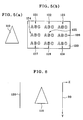
- an original image 110 having such conical shape as depicted in Fig. 5(a) and nine original images 121-129 defined on an image plane 120 are recorded on the same recording surface 20.
- the original image 110 used herein is a visually perceivable 3D image of about 10 mm in height, as is the case with the aforesaid original image 11, and the original images 121-129 are each a plane image comprising visually unperceivable micro-characters of about 200 ⁇ m in height, as is the case with the aforesaid original image 12.
- the recording surface 20 is located on an XY plane (with the X-axis being vertical to the paper), the original image 110 is placed in the rear of the recording surface 20 (in the left-hand direction of the paper), and the image plane 120 with the original images 121-129 formed thereon is placed in a further rear thereof.
- Fig. 7 is a front view of these original images as viewed from the recording surface 20 side.
- the conical original image 110 is located in front of the image plane 120, and the original images 121-129 formed on the image plane 120 and comprising micro-characters have a so-called background function in terms of design.
- the reconstructed image to be observed is a hologram reconstructed image having a depth on a three-dimensional space, so that although depending on the angle of viewing, there is a change in the location of the original image 110 relative to the original images 121-129 that form the background.
- the original images 121-129 are each shown in the form of a perceivable character string in Figs. 5 and 7 ; in practical applications, however, such characters are visually unperceivable micro-characters or they are visually only observed in the form of a striped pattern.
- ten sets of original images 110 and 121-129 in all are recorded on the recording surface 20.
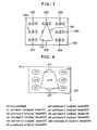
- ten areas ⁇ 1 to ⁇ 10 are defined on the recording surface 20 as shown in Fig. 8 , and any one of attributes 1 to 10 is defined in each area. It is noted that in an area ⁇ 0 in Fig. 8 (which is located outside of the ten areas ⁇ 1 to ⁇ 10), there is no need of recording interference fringes or a non-attribute is defined.
- the attributes 1 to 10 are parameters indicative of the original images 121-129 and 110, respectively; the area ⁇ 1 having attribute 1 allocated thereto is recorded with original image 121, the area ⁇ 2 having attribute 2 allocated thereto is recorded with original image 122, ..., the area ⁇ 9 having attribute 9 allocated thereto is recorded with original image 129, and the area ⁇ 10 having attribute 10 allocated thereto is recorded with original image 110. It is noted that the area ⁇ 5 having attribute 5 allocated thereto does not practically exist because it is hidden behind the area ⁇ 10. According to the computer-generated hologram fabrication process of the present invention, ten original images 110 and 121-129 are defined as shown in Fig. 7 , and then ten recording areas ⁇ 1- ⁇ 10 are defined on the recording surface 20.
- sample light sources are defined on each original image at a given spatial density.
- sample light sources are defined at a low density for original image 110 because of being of visually perceivable size, and at a high density for each of original images 121-129 because of being of visually unperceivable size.
- given reference light R is defined for the recording surface 20 and a multiplicity of computation points are defined on the recording surface 20.
- the intensity of interference waves of object light emitted from each original image and reference light is computed.
- it is noted that when performing computation on each computation point it is required to take into consideration only the object light coming from a sample point on the original image indicated by the attribute that the area to which said computation point is allocated has.
- a given interference fringe pattern is determined for each of areas ⁇ 1- ⁇ 10.
- a computer-generated hologram formed by defining areas ⁇ 1- ⁇ 10 on the recording surface in such a way that only information about one original image is recorded for each area is not an intrinsic hologram, as also referred to in ⁇ 1. That is, the rudimental principles of a hologram are that "information on one arbitrary point on an original image is recorded all over a recording surface". With a hologram that is fabricated by recording only information on a specific original image for each individual area, it is thus impossible to reconstruct any desired 3D image.
- the field angle for viewing becomes narrow, and so when the recording surface 20 is viewed from an oblique direction, it is impossible to reconstruct any right image.
- even such a hologram has no practically grave problem because of functioning well as an anti-counterfeiting mark for credit cards or notes.
- the locations and configurations of the areas ⁇ 1- ⁇ 10 defined on the recording surface 20 are approximate to those of the original images 121-129 and 110 shown in Fig. 7 .
- the location and configuration of each area are defined on the recording surface 20 in such a way as to approximate to those of each original image projected onto the recording surface 20. This is because the spatial location of each reconstructed image must be observed in similar relations as in the spatial location of each original image.
- the area ⁇ 0 to which the non-attribute is allocated takes no part in the formation of the reconstructed image because there is no recorded interference fringe pattern.
- the character string "ABC” is thought of as one original image, and the embodiment shown in Fig. 7 is described with reference to a total of 10 original images 110 and 121-129.
- the "one original image” used herein is an arbitrary definition; one single character may be thought of as one original image, and a character string group comprising a number of character strings may be regarded as one original image.
- Fig. 9 shows one example where character strings of ABC are arranged in three rows and three columns are thought of as one original image. This example may be dealt with on assumption that three original images 131, 132 and 133 are provided on an image plane 130.
- Fig. 10 is illustrative of one example of an area definition corresponding to Fig. 9 , wherein five areas ⁇ 1- ⁇ 5 are defined on a recording surface 20 with an area ⁇ 0 having a non-attribute.
- An attribute 1 is allocated to area ⁇ 1 with information about the first original image 131 recorded therein.
- An attribute 2 is allocated to areas ⁇ 2 and ⁇ 3 with information on the second original image 132 recorded therein, an attribute 3 is allocated to area ⁇ 4 with information about the third original image 133 recorded therein, and an attribute 4 is allocated to area ⁇ 5 with information about the fourth original image 110 recorded therein.
- the field angle with respect to the horizontal direction becomes wide.
- the area ⁇ 1 of Fig. 10 is recorded with the original image 131 depicted in Fig. 9 , i.e., information consisting of three sets of "ABC" character strings arranged in the horizontal direction; even when they are observed in an oblique right-hand or left-hand direction, the intended 3D reconstructed image may be obtained.
- the amount of computations on all computation points within this area ⁇ 1 increases unavoidably, because object light coming from all sample light sources on the original image 131 must be taken into consideration.
- the areas on the recording surface 20 are defined in conformity with the locations and configurations of the original images.
- the areas ⁇ 1- ⁇ 10 depicted in Fig. 8 are located and configured in conformity with the original images 121-129 and 110 shown in Fig. 7 .
- Such area definition can easily be achieved by limiting to a given angle the angle of spreading of object light emitted from individual sample light sources defined on the original images. By such limitation to the angle of spreading, it is possible to determine a specific condition that enables object light emitted from a sample light source on a k-th original image to reach only within an area having a k-th attribute.
- a recording surface 20 is defined on an XY plane (with the X-axis being in a direction vertical to the paper) and information about an original image 10 located in the rear thereof (in the left-hand direction) is recorded on the recording surface 20, as shown in Fig. 11 .
- an i-th sample light source Pi defined on the original image 10 were a point light source.
- Object light emitted from this sample light source Pi will take the form of spherical waves arriving at the whole recording surface 20.
- the angle of spreading in the Y-axis direction of object light emitted from the sample light source Pi is limited to an angle ⁇ y with the center on a perpendicular (parallel with the Z-axis) to the recording surface 20 as shown in Fig. 11 , the object light coming from the sample light source Pi will arrive at only a portion Ly of the width of the recording surface 20.
- the angle of spreading of the object light in the X-axis direction is limited to an angle ⁇ x
- the object light coming from the sample light source Pi will arrive at only a portion of unit area Ui on the recording surface 20, as shown in Fig. 12 .
- the unit area Ui in this case becomes a rectangular area wherein the lengths in the X-axis and Y-axis directions are given by Lx and Ly, respectively, as hatched in Fig. 12 .
- the rectangular area whose lengths in the X-axis and Y-axis directions are given by Lx and Ly, respectively, is defined as an area at which object light emitted from an individual sample light source arrives.
- the same technique is used to limit the angles of spreading of object light coming from all of N sample light sources defined on the original image 10
- information about the original image 10 is recorded only within a specific area comprising a set of all of N rectangular areas (that overlap one another) defined on the recording surface 20.
- the specific limiting condition is set for the angle of spreading of object light emitted from each sample light source on the original image, the area on the recording surface 20 is uniquely defined.
- sample light source for which any one of point, linear and surface light sources may be used.
- point light sources are used as all sample light sources, only the determination of information about their positions on the original image is needed for the definition of the sample light sources. It is here noted that the intensity of object light is determined depending on the luminance, reflectivity, etc. of the original image at the positions of sample light sources. How to define the positions of sample light sources is now explained, utilizing a plurality of mutually parallel sections.
- a section Sj shown in Fig. 13 represents a j-th section of the plurality of sections.
- a j-th sectional line Lj is defined as shown in Fig. 13
- a j-th sectional line Mj is defined as shown in Fig. 13 .
- the sectional line Mj formed on the recording surface 20 side is called a line of intersection Mj.
- Fig. 14 is a side view illustrative of how a multiplicity of sample light sources are defined on the surface of an original image 10. As shown, a total of J sections S1-SJ (that are all parallel with the XZ plane) are defined while adjacent sections are spaced away from each other at a given spacing D. If J sections S1-SJ are defined in this way, J sectional lines L1-LJ are defined on the original image 10 side at a given spacing D and J lines of intersection M1-MJ (vertical to the paper) are defined on the recording surface 20 side at a given spacing D.
- sample light sources are defined on each of sectional lines L1-LJ at a given spacing d (that may be either a straight line spacing or an spacing of distance along each section), then it is possible to regularly define a multiplicity of sample light sources on the surface of the original image 10. As shown typically in Fig. 14 , sample light sources Pj1, Pj2, Pj3, ... are defined on a j-th sectional line Lj. Y-coordinate values for these sample light sources Pj1, Pj2, Pj3, ... coincide with the Y-coordinate value for a j-th line of intersection Mj on the recording surface 20 side.
- a (j+1)-th sectional line L(j+1) formed by a (j+1)-th section S(j+1) is defined, and a multiplicity of sample light sources (not shown) are defined on this sectional line L(j+1) at a given spacing d.
- the Y-coordinate values for these sample light sources coincide with the Y-coordinate value for a (j+1)-th line of intersection M(j+1).
- the feature of the present invention comprises that the spatial density of sample light sources is varied for each original image.
- sample light sources are defined utilizing sections as explained above, it is then possible to vary the section-to-section spacing D or the spacing d between the sample light sources located on the sectional line, thereby varying the spatial density of the sample light sources.
- both the intervals d and D should be varied in association with each other (otherwise, there may possibly be a case where the longitudinal resolution of a reconstructed image differs extremely from the lateral resolution thereof), because the section-to-section spacing D is a determinative factor for the longitudinal density of sample light sources and the spacing d between the sample light sources is a determinative factor for the lateral density of sample light sources.
- a specific condition is set in such a way as to ensure that d is constantly equal to D/2; once the section-to-section spacing D has been determined, the spacing d between the sample light sources located on the sectional line can automatically be determined.
- a plurality of sections located in such a way that they are kept parallel with each other at the given spacing D are defined, and sample light sources arranged at the given spacing d on the sectional line obtained by cutting the surface of the original image 10 by each sectional line are defined.
- sample light sources arranged at the given spacing d on the sectional line obtained by cutting the surface of the original image 10 by each sectional line are defined.
- the section-to-section spacing D can be varied for each original image, so that the spatial density of sample light sources can easily be varied.
- the section-to-section spacing D it is preferable that 30 ⁇ m or greater (e.g., 80 ⁇ m) is used for a visually perceivable original image (at less than 30 ⁇ m, the resolution becomes higher required, ending up with useless computations), and 30 ⁇ m or less (e.g., 20 ⁇ m) is used for a visually unperceivable original image (e.g., micro-characters of 100 ⁇ m in height and 50 ⁇ m in width) (at 30 ⁇ m or greater micro-characters, etc. cannot be represented with adequate resolution).
- Fig. 14 sample light sources comprising point light sources are defined utilizing a plurality of sections, and the angles of spreading of object light emitted from individual sample light sources are limited, so that the intensity of interference waves is computed on each computation point on a recording surface 20.
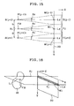
- Fig. 15 is a side view of how to set the angles of spreading, showing a portion of Fig. 14 on an enlarged scale.
- An i-th sample light source P(j-1) i defined on a sectional line by a(j-1)-th section S(j-1), an i-th sample light source Pji defined on a sectional line by a j-th section Sj, and an i-th sample light source P(j+1) i defined on a sectional line by a (j+1)-th section S(j+1) are shown as typical sample light sources.
- Shown by black circles are a line of intersection M(j-1) with the (j-1)-th section S(j-1), a line of intersection Mj with the j-th section Sj and a line of intersection M(j+1) with the (j+1)-th section S(j+1).
- strip areas T(j-1), Tj and T(j+1) are defined by allowing the lines of intersection M(j-1), Mj and M(j+1) to have widths Ly in the Y-axis direction.
- each strip area is in a rectangular form, which is slender in the lateral (X-axis) direction, and whose width in the Y-axis direction is given by Ly and whose width in the X-axis direction is given by the lateral width of the recording surface 20 with the center line defined by each line of intersection.
- the recording surface 20 is shown on the right-hand side of Fig. 15 ; in practical applications, however, each strip area is given by a rectangular area defined on the recording surface 20.
- the recording surface 20 is thoroughly filled up with a number of strip areas, as shown. Then, if the angle of spreading, ⁇ y, in the Y-axis direction of object light emitted from each sample light source is set in such a way that the area irradiated with the object light comes within one strip area, for instance, object light from the sample light source P(j-1)i reaches only within the strip area T(j-1), object light from the sample light source Pji reaches only within the strip area Tj, and object light from the sample light source P(j+1)i reaches only within the strip area T(j+1).
- Fig. 16 is a perspective schematic illustrative of what relation a sample light source Pji defined on an original image 10 has to a strip area Tj defined on a recording surface 20.
- a sample light source Pji is an i-th sample light source out of a multiplicity of sample light sources located at a given spacing d on a j-th sectional line Lj defined by cutting the original image 10 by a j-th section Sj.
- an interference fringe pattern obtained on the recording surface 20 does not provide an intrinsic hologram pattern, resulting in a failure in obtaining a correct 3D reconstructed image.
- a reconstructed image obtained from such a hologram ensures an adequate 3D appearance with respect to the X-axis (lateral) direction, but does not apply any adequate 3D appearance with respect to the Y-axis (longitudinal) direction.
- a plurality of strip areas T1, T2, ..., Tj, ..., TJ corresponding to a plurality of sections are defined, and a multiplicity of computation points are defined in each strip area (for instance, in a matrix pattern having a pitch of 0.6 ⁇ m in the X-axis direction and a pitch of 0.25 ⁇ m in the Y-axis direction), so that on computation points within the j-th strip area Tj, the intensity of interference waves is computed. What is necessary in this case is only to give consideration to object light from sample light sources located on the j-th sectional line Lj corresponding to the j-th strip area.
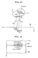
- Fig. 17 is a top view illustrative of how object light behaves when both the angles of spreading in the X-axis and Y-axis directions are limited.
- a multiplicity of sample light sources at a given spacing d there are defined a multiplicity of sample light sources at a given spacing d, as shown in Fig. 12 .
- object light from an i-th sample light source Pji will reache only within a unit area Uji on a recording surface 20 and object light from a (i+3)-th sample light source Pj(i+3) will reach only within a unit area Uj(i+3) on the recording surface 20.
- object light from a (i+1)-th sample light source Pj(i+1) will reach only within a unit area Uj(i+1) on the recording surface 20 and object light from a (i+2)-th sample light source Pj(i+2) will reach only within a unit area Uj(i+2) on the recording surface 20, although not shown in fig. 17 .
- the unit areas Uji, Uj(i+1), Uj(i+2) and Uj(i+3) are slightly displaced while they overlap.
- object light from a (i+n)-th sample light source Pj(i+n) defined on the back side of an original image 10 is negligible unless the original image 10 is a transparent object (subjected to the so-called hidden surface removal processing).
- Fig. 18 is a front view of the recording surface 20 of Fig. 17 as viewed from the original image 10 side.
- unit areas Uji and Uj(i+3) positioned on a line of intersection Mj, at which, as shown in Fig. 17 , object light beams from sample light sources Pji and Pj(i+3) on the sectional line Lj arrive, as well as unit areas U(j+1)i and U(j+1)(i+3) positioned on a line of intersection M(j+1), at which object light beams from sample light sources P(j+1) i and P(j+1)(i+3) that go down by a given spacing D arrive. It is understood that on the recording surface 20 there are defined a multiplicity of unit areas that are not shown in Fig.
- a specific unit area on the recording surface 20 corresponds to a specific sample light source on the original image 10.
- the unit area Uji on the recording surface 20 corresponds to the specific sample light source Pji on the original image 10.
- the computations may be performed as follows.
- the intensity of interference waves When computing the intensity of interference waves with respect to a certain one computation point on the recording surface 20, it is first required to identify some unit areas inclusive of said computation point. Then, the intensity of interference waves should be computed while only object light beams from sample light sources corresponding to these unit areas are taken into account.
- Fig. 8 are automatically defined with the proviso that such some original images as shown in Fig. 7 are provided.
- a number of sample light sources are defined on an original image 110.
- Object light beams from individual sample light sources on the original image 110 then reach only within given unit areas on the recording surface 20, so that an area comprising a set of these unit areas is automatically defined as the area ⁇ 10 shown in Fig. 8 .
- a slender area constructed of a plurality of unit areas lined up on the same line of intersection can be thought of as a strip area (for instance, if an area made up of J unit areas Uj1, Uj2, ..., Uji, ..., UjJ lined up on the line of intersection Mj can be thought of as a strip area Tj), then the latter case would be tantamount in construction to the former case, because a multiplicity of strip areas are located in the Y-axis direction.
- the width Ly of the strip area in the Y-axis direction (or the width of the unit area in the Y-axis direction) is made equal to the section-to-section spacing D, whereby the recording surface 20 is thoroughly filled up with a multiplicity of strip areas located in the Y-axis direction.
- the width Ly of the strip area may be made smaller than the section-to-section spacing D.
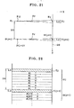
- Fig. 19 is a side schematic illustrative of how object light propagates when the angle of spreading ⁇ Y shown in Fig. 15 is set at a smaller angle. In Fig.
- strip areas T(j-1), Tj and T(j+1) are defined on a recording surface 20 as is the case with Fig. 15 , and on computation points within these strip areas, the intensity values of given interference waves are computed.
- Fig. 20 is a plan view of the recording surface 20 for explaining the principles of copying the results of computations with respect to strip areas to void areas.
- Strip areas T(j-1), Tj and T(j+1) are represented by hatched areas, and void areas between adjacent strip areas are represented by broken-line areas.
- the intensity values of interference waves are found on computation points distributed in each strip area; however, no results of computations are obtained with respect to the void areas at all.
- the results of computation obtained with respect to the interior of the strip area T(j-1) for instance are copied to three void areas ⁇ (j-1)1, ⁇ (j-1)2 and ⁇ (j-1)3, the results of computation found with respect to the interior of the strip area Tj are copied to three void areas ⁇ j1, ⁇ j2 and ⁇ j3, and the results of computation obtained with respect to the interior of the strip area T(j+1) are copied to three void areas ⁇ (j+1)1, ⁇ (j+1)2 and ⁇ (j+1)3.
- each of the areas indicated by groups G(j-1), Gj and G(j+1) may be regarded as an area where four strip areas having the same interference fringes recorded therein are located in a continuously repetitive fashion.
- the feature of the present invention comprises that the spatial density of sample light sources varies for each original image.
- the void areas enlarge so that when the contents of interference fringes in the strip areas are copied to the void areas, the number of repetition increases accordingly.
- it is required to copy the results of computations obtained on the interior of the strip area Tj to seven void areas ⁇ j1 to ⁇ j7, as shown in Fig. 22 .
- the area given by group Gj in Fig. 22 provides an area where eight strip areas having the same interference fringes recorded therein are located in a continuously repetitive fashion.
- hologram-recorded medium used herein broadly means a hologram optical pattern fixed on a physical medium of some kind, said pattern being formed on a recording surface 20 by means of computer-aided computations, and so includes, for instance, a master hologram with an interference fringe pattern written thereon using an electron beam lithographic system, a replica fabricated using this master hologram, and a medium obtained by providing a film form of reflecting layer on the replica.
- the rudimentary features of the hologram-recorded medium according to the present invention are that a plurality of original images are recorded, information is recorded in a separate recording area for each original image, information carried by object light emitted from a multiplicity of sample light sources defined on the original images to be recorded is recorded in individual recording areas, and the spatial densities of sample light sources on at least two different original images differ from each other.
- a hologram-recorded medium wherein an interference fringe pattern formed on a recording surface 20 shown in Fig. 8 as an example is physically fixed, a total of ten original images 121-129 and 110 are recorded.
- the spatial density of sample light sources on the original image 110 differs from that of sample light sources on the original images 121-129. More specifically, the original image 110 is a visually perceivable image whereas the original images 121-129 are each an image comprising visually unperceivable micro-characters (characters having a maximum size of 300 ⁇ m or less), and the spatial density of sample light sources on the original images 121-129 is made higher than that on the original image 110.
- a multiplicity of sections should be defined in such a way as to be kept parallel with each other at a given spacing D, as already explained, so that groups of sample light sources are defined on sectional lines formed by the sections, thereby varying the given spacing D for each original image.
- the spacing D should be set at 30 ⁇ m or greater for a visually perceivable original image like the original image 110 so that a multiplicity of sections can be defined, and the spacing D should be set at less than 30 ⁇ m for visually unperceivable original images like the original images 121-129 so that a multiplicity of sections can be defined.
- a multiplicity of strip areas of the same rectangular shape are lined up on the recording surface, so that given interference fringes are recorded in each strip area and a given number of strip areas having the same interference fringes recorded therein are located in a continuously repetitive fashion. It is understood that with the fundamental features of the hologram-recorded medium according to the present invention, there is achieved a unique structure wherein a separate recording area is defined on the recording surface for each original image, and the number of continuously lined-up strip areas having the same interference fringes recorded therein differs with respect to at least two recording areas.
- the number of continuously lined-up strip areas having the same interference fringes recorded therein is four as shown in Fig. 20 .
- the number of continuously lined-up strip areas having the same interference fringes recorded therein is eight as shown in Fig. 22 .
- the hologram-recorded medium having such features as mentioned above may be fabricated by the processes explained in ⁇ 1 through ⁇ 3, and has the merit of lifting up loads on computations for obtaining interference fringe patterns.
- the hologram-recorded medium of the present invention affords convenience to commercial mass-production.
- the computer-generated hologram fabrication process and the hologram-recorded medium according to the present invention may be used in combination with a method of recording the original images using a diffracting grating pattern.
- a pattern comprising a diffraction grating or the like may be formed in the area ⁇ 0 in Fig. 8 or Fig. 10 .
- four original images 121, 123, 127 and 129 out of a plurality of original images shown in Fig. 7 may be each recorded in the form of a diffraction grating pattern rather than interference fringes.
- information about original images is recorded on the recording surface 20 in the form of interference fringes of object light and reference light according to the basic principles shown in Fig. 1 .
- the computer-generated hologram methodology it is not always necessary to record the original image 10 in the form of interference fringes using reference light R; object light from the original image 10 may be recorded as such directly on the recording surface 20. That is, when a hologram is optically fabricated, it is required to generate interference waves on a recording medium 20 comprising a photosensitive material over the constant time needed for photosensitization and record them as interference fringes. For this reason, it is required to generate interference waves that become stationary waves, utilizing reference light.
- a sample light source (point light source) P and a recording surface 20 are defined as shown in the perspective view of Fig. 23 , and consider how the amplitude and phase of object light arriving at a computation point Q(x, y) on the recording surface 20 is computed.
- wave motion is generally represented by the following complex function: Acos ⁇ + i Asin ⁇ where i is the imaginary unit, A is a parameter indicative of amplitude and ⁇ is a parameter indicative of phase.
- object light at the position of computation point Q(x, y) is given by the following complex function: A / r ⁇ cos ⁇ + 2 ⁇ ⁇ r / ⁇ + i A / r ⁇ sin ⁇ + 2 ⁇ ⁇ r / ⁇
- r is the distance between the point light source P and the computation point Q(x, y)
- ⁇ is the wavelength of object light.
- the amplitude of object light attenuates with increasing distance r, and the phase is determined depending on the distance r vs. wavelength ⁇ relationship.
- This complex function has no variable indicative of time, because of being a function indicative of a momentary state of the wave observed when time is at a standstill at a given reference time.
- a multiplicity of sample light sources i.e., point light sources P1, P2, ..., Pk, PK should be defined on the original image 10, and the amplitude and phase of the combined wave of object light emitted from each point light source are found by computation at the position of each computation point on the recording surface 20, followed by recording of them by some means.
- object light emitted from a k-th point light source Pk is represented by such a complex function as shown in Fig.
- the amplitude of the combined wave of object light at the computation point Q(x, y) is given by a distance A(x, y) between the origin O and the coordinate point V on the coordinate plane of Fig. 25 , and the phase is given by an angle ⁇ (x, y) of a vector OV with a real number axis.
- the amplitude A(x, y) and phase ⁇ (x, y) of the combined wave of object light at the position of any arbitrary computation point Q(x, y) defined on the recording surface 20 is found by calculation.
- the complex amplitude distribution (the distribution of the amplitude and phase of the combined wave of object light) of object light emitted from the original image 10 is obtained on the recording surface 20.
- the thus obtained complex amplitude distribution is physically recorded on a physical recording medium by some means in such a way that upon illumination with given reconstructing light, the wavefronts of object light are reconstructed. In this way, the original image 10 can be recorded on the physical recording medium.
- a three-dimensional cell may be used to record on the recording surface 20 the complex amplitude distribution of object light emitted from the original image 10.
- the complex amplitude distribution is recorded using the three-dimensional cell to record the original image 10 as a hologram, it is preferable to carry out such steps as set forth just below.
- a set 30 of three-dimensional virtual cells are first defined at the position of the recording surface 20.
- virtual cells in the form of blocks having given size are arranged two-dimensionally in a matrix arrangement.
- one single virtual cell is assumed to have one computation point therein.
- the computation point may be positioned at any one single point within the cell, it is here understood that the computation point is located at the position of the central point of the front surface of the cell (which faces the original image 10).
- an XY coordinate system is defined on the front surface of the three-dimensional virtual cell set 30 (which faces the original image 10).
- a virtual cell having a certain computation point Q(x, y) at a position on coordinates (x, y) in this coordinate system is called a virtual cell C(x, y)
- the computation point Q(x, y) is positioned at the central point of the front surface of that virtual cell C(x, y).
- one single virtual cell should preferably be positioned in the vicinity of one computation point.
- the original image 10 On the original image 10, on the other hand, there are defined a multiplicity of sample light sources, as already explained.
- the original image 10 is defined as a set of K point light sources P1, P2, ..., Pk, PK.
- the complex amplitude of this combined wave may be calculated from the aforesaid formulae, and shown as a coordinate point V on the complex coordinate plane shown in Fig. 25 . Based on this coordinate point V, the amplitude A(x, y) and phase ⁇ (x, y) are obtained as already set forth.
- the amplitude A(x, y) and phase ⁇ (x, y) obtained on the computation point Q(x, y) is called a specific amplitude A(x, y) and a specific phase ⁇ (x, y) with respect to said computation point Q(x, y).
- the physical cell must have specific optical properties in such a way that upon receipt of specific incident light, the amplitude and phase of the incident light vary depending on the specific amplitude and specific phase defined for the corresponding virtual cell, thereby producing emergent light.
- an optical element comprising a set of physical cells, each having such specific optical properties, is irradiated with given reconstructing illumination light (that is ideally a chromatic light plane wave having the same wavelength as that of object light used in the aforesaid computation processing), then the reconstructing illumination light is modulated by the specific amplitude and phase at an individual physical cell, resulting in reconstruction of the wavefronts of the object light. In this way, the hologram recorded in the optical element is reconstructed.
- reconstructing illumination light that is ideally a chromatic light plane wave having the same wavelength as that of object light used in the aforesaid computation processing
- the physical cell used herein is a three-dimensional cell that is not critical in construction with the exception that a specific amplitude and a specific phase are defined thereon; the essential optical requirement therefor is that upon receipt of given incident light, there is obtained emergent light in which the amplitude and phase of incident light are changed depending on the specific amplitude and specific phase defined on said cell.
- the amplitude Ain of incident light changes to the amplitude Aout upon modulation by the specific amplitude A(x, y) recorded in the cell
- the phase ⁇ in of incident light changes to the phase ⁇ out upon modulation by the specific phase ⁇ (x, y) recorded in the cell.
- One method of amplitude modulation in the three-dimensional cell is to allow the cell to have therein an amplitude modulation region having a transmittance consistent with a specific amplitude.
- the whole cell may be designed as an amplitude modulation region or a part of the cell may be provided with an amplitude modulation region.
- Aout Average
- Setting the transmittance of individual three-dimensional cells at any desired value may be achieved by varying the content of a coloring agent therein.
- Setting the reflectivity of individual three-dimensional cells at any desired value may be achieved by providing a reflecting surface in the cell (which functions as an amplitude modulation region) and setting the reflectivity of this reflecting surface at any desired value. More specifically, the ratio of reflected light and scattered light may be regulated by varying the surface roughness of the reflecting surface; it is possible to provide a cell having any desired reflectivity by regulation of that reflecting surface.
- phase modulation in a three-dimensional cell is to allow the cell to have therein a phase modulation region having a refractive index consistent with a specific phase.
- the whole cell may be designed as a phase modulation region or a part of the cell may be provided with a phase modulation region.
- a cell having a phase modulation region formed of a material having a refractive index of n1 and a cell having a phase modulation region formed of a material having a refractive index of n2 there is a difference in the phase of emergent light, even upon the application thereto of incident light having the same phase. Accordingly, if a cell is made up of various materials having varying refractive indices, incident light can then be subjected to any desired phase modulation.
- phase modulation in a three-dimensional cell is to allow the cell to have therein a phase modulation region having an optical path length consistent with a specific phase.
- the whole cell may be designed as a phase modulation region or a part of the cell may be provided with a phase modulation region.
- Emergent light leaving the second cell will be twice longer than emergent light leaving the first cell in terms of the length of the optical path taken by the incident light through the material having a refractive index of n . Thus, there is some large phase difference.
- three-dimensional cells having an amplitude modulation function based on a specific amplitude or a phase modulation function based on a specific phase may be achieved by several methods, and any desired selection may be made from the aforesaid several amplitude or phase modulation methods. For instance, if the whole cell is used as an amplitude modulation region formed therein with a transmittance consistent with a specific amplitude and a phase modulation region formed therein with a refractive index consistent with a specific phase, it is then possible to form an optical element by selective arrangement of such 16 physical cells as shown in the table of Fig. 27 with amplitude A as abscissa and phase ⁇ as ordinate; amplitude A, and phase ⁇ being divided into four ranges.
- the cells depicted in the range with amplitude A corresponding to "0 to 25%" are formed of a material having a very low transmittance
- the cells depicted in the range with amplitude A corresponding to "25 to 50%" (those in the second row) a material having a somewhat low transmittance
- the cells depicted in the range with amplitude A corresponding to "50 to 75%” (those in the third row) a material having a somewhat high transmittance
- the cells depicted in the range with amplitude A corresponding to "75 to 100%" (those in the fourth row) a material having a very high transmittance.
- the cells depicted in the range with phase ⁇ corresponding to "0 to ⁇ /2" are formed of a material having a refractive index n1 that is very close to that of air
- the cells depicted in the range with phase ⁇ corresponding to " ⁇ /2 to ⁇ " (those in the second column) a material having a refractive index n2 that is somewhat larger than that of air
- the cells depicted in the range with phase ⁇ corresponding to " ⁇ to 3 ⁇ /2" (those in the third column) a material having a refractive index n3 that is larger than that of air
- the cells depicted in the range with phase ⁇ corresponding to "3 ⁇ /2 to 2 ⁇ " (those in the fourth column) a material having a refractive index n4 that is much larger than that of air.
- a total of 16 cells having four transmittances and four refractive indices are in readiness for recording.
- the virtual cells are replaced by 16 such physical cells, it is preferable to selectively use physical cells having optical properties closest to those needed for modulation by a specific amplitude and a specific phase defined for each virtual cell.
- Fig. 28 is a perspective schematic illustrative of one exemplary structure of a physical cell C(x, y) capable of amplitude modulation and phase modulation by yet another method.
- this three-dimensional physical cell has a substantially cuboidal block form, and is provided on its surface with a groove G(x, y).
- the physical structure C(x, y) having such structure it is then possible to record amplitude information as the value of the lateral width G1 of the groove G(x, y) and record phase information as the value of the depth G2 of the groove G(x, y).
- This is because there is a difference in the index of refraction between the interior of the physical cell C(x, y) and the outside air, and so there is a difference in the optical path taken by light through the outside space between light L1 incident vertically on the bottom surface S1 of the groove G(x, y) and light L2 incident vertically on the surfaces S2 of both sides of the groove G(x, y).
- the width G1 and depth G2 of the groove is continuously variable, and so it is theoretically possible to keep unlimited types of physical cells in readiness. It is thus possible to replace virtual cells by physical cells selected from unlimited types of physical cells and having a precise groove width G1 consistent with a specific amplitude on said virtual cells and a precise depth G2 consistent with a specific phase defined thereon. In practical applications, however, it is preferable to select physical cells having optical properties closest to the necessary optical properties from a total of a ⁇ b physical cells where a is the number of predetermined groove widths and b is the number of predetermined groove depths.
- FIG. 29 is a perspective schematic illustrative of a total of 28 physical cells having seven predetermined groove widths and four predetermined groove depths.
- Each of the 28 physical cells is a physical cell in such a form as shown in Fig. 28 .
- Fig. 29 is illustrative of these physical cells being located in a matrix arrangement with four columns and seven rows.
- the seven rows of the matrix arrangement shown in Fig. 29 are indicative of variations of amplitude A, and the four columns are indicative of variations of phase ⁇ .
- the amplitude A increases in order from row W2 to W7 or from the left to the right, and the groove width G1 becomes gradually wide, correspondingly.
- the phase ⁇ increases in order from V2 to V4 or from above to below, and the groove depth G2 becomes gradually large, correspondingly.
Claims (12)
- Procédé de fabrication d'un hologramme généré par ordinateur ayant des franges d'interférence synthétisées par des calculs assistés par ordinateur et ensuite enregistrées sur une surface d'enregistrement donnée, qui comprend des étapes consistant à :définir 2 à K objets originaux (10), une surface d'enregistrement (20) destinée à enregistrer les franges synthétisées à partir des objets originaux, et une lumière de référence avec laquelle la surface d'enregistrement est illuminée, etdéfinir une multiplicité de sources de lumière d'échantillonnage sur chaque objet original et définir une multiplicité de points de calcul sur la surface d'enregistrement,moyennant quoi pour chaque point de calcul (Q(x,y)), l'intensité des ondes d'interférence formées par la lumière d'un objet provenant de la totalité ou de quelques-unes des sources de lumière d'échantillonnage définies sur un objet et la lumière de référence est trouvée par des calculs de sorte que les franges d'interférence ayant la distribution d'intensités ainsi trouvée soient formées sur la surface d'enregistrement en tant qu'hologramme pour les K objets originaux,dans lequel :les réglages du procédé sont tels que des densités spatiales de sources de lumière d'échantillonnage définies sur au moins deux objets originaux différents diffèrent les unes des autres,caractérisé en ce que la surface d'enregistrement (20) est divisée en une pluralité de zones (α1, α2), chacun des K objets étant attribué à une zone, de sorte que, par rapport aux points de calcul dans chacune desdites zones dans laquelle un kème, k = 1 à K, objet est attribué, une intensité d'ondes d'interférence soit calculée en prenant en considération seulement la lumière d'un objet émise par les sources de lumière d'échantillonnage sur le kème objet original, et que des informations sur le kème objet original soient enregistrées dans une seule zone dans laquelle le kème objet est défini en tant que kème attribut atribué.
- Procédé de fabrication d'un hologramme généré par ordinateur ayant un motif optique synthétisé par calculs assistés par ordinateur et formé ensuite sur une surface d'enregistrement donnée, qui comprend des étapes consistant à :définir 2 à K objets originaux et une surface d'enregistrement destinée à l'enregistrement du motif synthétisé à partir des objets originaux, etdéfinir une multiplicité de sources de lumière d'échantillonnage sur chaque objet original et définir une multiplicité de points de calcul sur la surface d'enregistrement de sorte que, pour chaque point de calcul, l'amplitude complexe à une position dudit point de calcul de la lumière d'un objet provenant de la totalité ou de quelques-unes des sources de lumière d'échantillonnage définies sur un objet soit calculée,définissant de cette façon une amplitude spécifique et une phase spécifique en chaque point de calcul, et localisant une cellule physique ayant des propriétés optiques cohérentes avec ladite amplitude spécifique et avec ladite phase spécifique au voisinage de chaque point de calcul, de sorte qu'une surface d'enregistrement d'hologramme soit formée par un ensemble de cellules physiques, dans lequel :les réglages du procédé sont tels que les densités spatiales des sources de lumière d'échantillonnage définies sur au moins deux objets originaux différents diffèrent les unes des autres,caractérisé en ce que la surface d'enregistrement (20) est divisée en une pluralité de zones (α1, α2), chacun des K objets étant attribué à une zone, de sorte que, par rapport aux points de calcul dans chacune desdites zones où un kème, k = 1 à K, objet est attribué, une amplitude complexe de la lumière d'un objet soit calculée en prenant en considération uniquement la lumière d'un objet émise par les sources de lumière d'échantillonnage sur le kème objet original, et que des informations sur le kème objet original sont enregistrées dans une seule zone dans laquelle le kème objet est défini en tant que kème attribut atribué.
- Procédé selon la revendication 1 ou 2, dans lequel un non-attribut est défini dans une zone dans laquelle un enregistrement d'une frange d'interférence sur un motif optique n'est pas respectivement nécessaire, et aucun calcul n'est effectué dans la zone, dans laquelle le non-attribut est défini, de sorte à ne former aucune frange d'interférence ou aucun motif optique dans ladite zone.
- Procédé de fabrication d'hologramme généré par ordinateur selon la revendication 1, 2 ou 3, dans lequel :un angle d'étalement de lumière d'un objet émise par chaque source de lumière d'échantillonnage est limité à un angle donné, définissant ainsi des conditions selon lesquelles la lumière d'un objet émise par une source de lumière d'échantillonnage sur un kème objet original atteint uniquement une zone ayant un kème attribut de sorte à calculer l'intensité d'ondes d'interférence ou l'amplitude complexe de la lumière d'un objet.
- Procédé de fabrication d'hologramme généré par ordinateur selon la revendication 4, dans lequel :la surface d'enregistrement est située sur un plan XY, de sorte que, par rapport à la lumière d'un objet émise par des sources de lumière d'échantillonnage, définies en tant que sources de lumière ponctuelles, vers une direction de l'axe Z, une limitation soit imposée à un angle d'étalement θx de la lumière d'un objet dans une direction de l'axe X et à un angle d'étalement θy de la lumière d'un objet dans une direction de l'axe Y.
- Procédé de fabrication d'hologramme généré par ordinateur selon l'une quelconque des revendications 1 à 5, dans lequel :une pluralité de sections situées parallèles les unes aux autres avec un espacement donné sont définies pour chaque objet original, et des sources de lumière d'échantillonnage disposées à un espacement donné sur une ligne de section obtenue en coupant la surface de l'objet original par chaque section sont définies, de sorte à varier la densité spatiale des sources de lumière d'échantillonnage par une variation d'un espacement entre des sections pour chaque objet original.
- Procédé de fabrication d'hologramme généré par ordinateur selon la revendication 6, dans lequel :la surface d'enregistrement coupe chaque section par une ligne donnée d'intersection ayant une largeur donnée afin de former une zone en forme de bande, et l'intensité des franges d'interférence ou l'amplitude complexe de la lumière d'un objet est calculée selon des conditions telles que la lumière d'un objet émise par des sources de lumière d'échantillonnage disposées sur une ligne de section obtenue par une jème section parvienne uniquement dans une zone en forme de bande formée par une ligne d'intersection de la jème section avec la surface d'enregistrement.
- Procédé de fabrication d'hologramme généré par ordinateur selon la revendication 7, dans lequel :la largeur de la zone en forme de bande est rendue plus étroite que l'espacement entre des sections, formant de cette façon sur la surface d'enregistrement un espace vide dans lequel aucune zone en forme de bande n'est définie, ledit espace vide étant utilisé pendant que les résultats de calcul des ondes d'interférence ou de l'amplitude complexe de la lumière d'un objet par rapport à une zone en forme de bande adjacente au dit espace vide sont copiés dans ce dernier.
- Procédé de fabrication d'hologramme généré par ordinateur selon l'une quelconque des revendications 1 à 8, dans lequel :un premier objet original de taille visuellement perceptible et un deuxième objet original de taille visuellement imperceptible sont définis, et une densité spatiale de sources de lumière d'échantillonnage définies sur le deuxième objet original est rendue plus grande que celle des sources de lumière d'échantillonnage définies sur le premier objet original, et dans lequel la taille imperceptible correspond à 300 µm ou moins.
- Procédé de fabrication d'hologramme généré par ordinateur selon la revendication 9, dans lequel :le deuxième objet original comprend un caractère.
- Procédé de fabrication d'hologramme généré par ordinateur selon la revendication 9 ou 10, dans lequel :une pluralité de sections situées parallèles les unes aux autres à un espacement donné sont définies et des sources de lumière d'échantillonnage disposées à un espacement donné sur une ligne d'intersection obtenue par la coupe de la surface de l'objet original par chaque section sont définies, etpour le premier objet original sont définies des sources de lumière d'échantillonnage à l'aide des sections situées à un espacement donné de 30 µm ou plus, et pour le deuxième objet original sont définies des sources de lumière d'échantillonnage à l'aide des sections situées à un espacement de moins de 30 µm.
- Support d'enregistrement d'hologramme dans lequel un motif optique d'hologramme fabriqué par le procédé de fabrication d'hologramme généré par ordinateur selon l'une quelconque des revendications 1 à 11 est enregistré.
Priority Applications (3)
| Application Number | Priority Date | Filing Date | Title |
|---|---|---|---|
| EP05026517.2A EP1777596B1 (fr) | 2002-12-18 | 2002-12-18 | Procédé de fabrication d'hologramme généré par ordinateur |
| EP02028431.1A EP1484652B1 (fr) | 2002-12-18 | 2002-12-18 | Hologramme généré par ordinateur et procédé pour sa fabrication |
| EP05026518A EP1777597A3 (fr) | 2002-12-18 | 2002-12-18 | Processus de fabrication d'un hologramme généré par ordinateur, et support de l'hologramme enregistré |
Applications Claiming Priority (2)
| Application Number | Priority Date | Filing Date | Title |
|---|---|---|---|
| JP2001383338 | 2001-12-17 | ||
| EP02028431.1A EP1484652B1 (fr) | 2002-12-18 | 2002-12-18 | Hologramme généré par ordinateur et procédé pour sa fabrication |
Related Child Applications (4)
| Application Number | Title | Priority Date | Filing Date |
|---|---|---|---|
| EP05026518A Division EP1777597A3 (fr) | 2002-12-18 | 2002-12-18 | Processus de fabrication d'un hologramme généré par ordinateur, et support de l'hologramme enregistré |
| EP05026517.2A Division EP1777596B1 (fr) | 2002-12-18 | 2002-12-18 | Procédé de fabrication d'hologramme généré par ordinateur |
| EP05026518.0 Division-Into | 2005-12-05 | ||
| EP05026517.2 Division-Into | 2005-12-05 |
Publications (2)
| Publication Number | Publication Date |
|---|---|
| EP1484652A1 EP1484652A1 (fr) | 2004-12-08 |
| EP1484652B1 true EP1484652B1 (fr) | 2013-10-23 |
Family
ID=37887936
Family Applications (3)
| Application Number | Title | Priority Date | Filing Date |
|---|---|---|---|
| EP05026517.2A Expired - Lifetime EP1777596B1 (fr) | 2002-12-18 | 2002-12-18 | Procédé de fabrication d'hologramme généré par ordinateur |
| EP02028431.1A Expired - Lifetime EP1484652B1 (fr) | 2002-12-18 | 2002-12-18 | Hologramme généré par ordinateur et procédé pour sa fabrication |
| EP05026518A Withdrawn EP1777597A3 (fr) | 2002-12-18 | 2002-12-18 | Processus de fabrication d'un hologramme généré par ordinateur, et support de l'hologramme enregistré |
Family Applications Before (1)
| Application Number | Title | Priority Date | Filing Date |
|---|---|---|---|
| EP05026517.2A Expired - Lifetime EP1777596B1 (fr) | 2002-12-18 | 2002-12-18 | Procédé de fabrication d'hologramme généré par ordinateur |
Family Applications After (1)
| Application Number | Title | Priority Date | Filing Date |
|---|---|---|---|
| EP05026518A Withdrawn EP1777597A3 (fr) | 2002-12-18 | 2002-12-18 | Processus de fabrication d'un hologramme généré par ordinateur, et support de l'hologramme enregistré |
Country Status (1)
| Country | Link |
|---|---|
| EP (3) | EP1777596B1 (fr) |
Cited By (1)
| Publication number | Priority date | Publication date | Assignee | Title |
|---|---|---|---|---|
| CN105764003A (zh) * | 2014-09-01 | 2016-07-13 | 三星电子株式会社 | 管理音频信号的方法和设备 |
Families Citing this family (2)
| Publication number | Priority date | Publication date | Assignee | Title |
|---|---|---|---|---|
| DE102017120536B4 (de) | 2017-09-06 | 2023-12-14 | Ovd Kinegram Ag | Verfahren zur Herstellung eines Hologramms, sowie ein Sicherheitselement und ein Sicherheitsdokument |
| DE102018123482A1 (de) * | 2018-09-24 | 2020-03-26 | Ovd Kinegram Ag | Optisch variables Element, Sicherheitsdokument, Verfahren zur Herstellung eines optisch variablen Elements, Verfahren zur Herstellung eines Sicherheitsdokuments |
Family Cites Families (6)
| Publication number | Priority date | Publication date | Assignee | Title |
|---|---|---|---|---|
| GB9025390D0 (en) * | 1990-11-22 | 1991-01-09 | De La Rue Thomas & Co Ltd | Security device |
| JPH06110371A (ja) * | 1992-09-30 | 1994-04-22 | Fujitsu Ltd | 立体表示方法及び装置 |
| JP3810917B2 (ja) * | 1998-01-20 | 2006-08-16 | 大日本印刷株式会社 | 計算機ホログラムおよびその作成方法 |
| JP3810961B2 (ja) * | 1999-09-17 | 2006-08-16 | 大日本印刷株式会社 | ホログラム記録媒体の製造方法 |
| JP3871837B2 (ja) * | 1999-09-30 | 2007-01-24 | 大日本印刷株式会社 | ホログラム記録媒体の製造方法 |
| US7699405B2 (en) | 2007-08-24 | 2010-04-20 | The Timken Company | Vehicle wheel end assemblies and methods of assembly thereof |
-
2002
- 2002-12-18 EP EP05026517.2A patent/EP1777596B1/fr not_active Expired - Lifetime
- 2002-12-18 EP EP02028431.1A patent/EP1484652B1/fr not_active Expired - Lifetime
- 2002-12-18 EP EP05026518A patent/EP1777597A3/fr not_active Withdrawn
Cited By (1)
| Publication number | Priority date | Publication date | Assignee | Title |
|---|---|---|---|---|
| CN105764003A (zh) * | 2014-09-01 | 2016-07-13 | 三星电子株式会社 | 管理音频信号的方法和设备 |
Also Published As
| Publication number | Publication date |
|---|---|
| EP1777597A2 (fr) | 2007-04-25 |
| EP1777596A3 (fr) | 2007-08-08 |
| EP1777597A3 (fr) | 2012-11-21 |
| EP1777596B1 (fr) | 2017-11-01 |
| EP1777596A2 (fr) | 2007-04-25 |
| EP1484652A1 (fr) | 2004-12-08 |
Similar Documents
| Publication | Publication Date | Title |
|---|---|---|
| US7123392B2 (en) | Computer-generated hologram fabrication process, and hologram-recorded medium | |
| US6813048B2 (en) | Computer-generated hologram fabrication process, and hologram-recorded medium | |
| EP1184747B1 (fr) | Elément optique et procédé de sa fabrication | |
| JP4984938B2 (ja) | 光学素子およびその製造方法 | |
| US7573622B2 (en) | Computer hologram and creation method thereof | |
| US6873444B1 (en) | Volume holograms in transparent materials | |
| JP3810934B2 (ja) | 計算機ホログラムおよびその作成方法 | |
| JP4256372B2 (ja) | 計算機ホログラムおよびその作成方法 | |
| EP1484652B1 (fr) | Hologramme généré par ordinateur et procédé pour sa fabrication | |
| JP3810961B2 (ja) | ホログラム記録媒体の製造方法 | |
| JP3892619B2 (ja) | 計算機ホログラムおよびその作成方法 | |
| US20010012156A1 (en) | Diffraction surfaces and methods for the manufacture thereof | |
| US20020131174A1 (en) | Diffraction surfaces and methods for the manufacture thereof | |
| JP2006065340A (ja) | ホログラム記録媒体 | |
| Stepien et al. | Distributed kinoforms in optical security applications | |
| US20020044271A1 (en) | Diffraction surfaces and methods for the manufacture thereof | |
| JPH1124541A (ja) | 計算機ホログラムおよびその作成方法 | |
| US20020036826A1 (en) | Diffraction surfaces and methods for the manufacture thereof | |
| AU1749595A (en) | Difraction surfaces and methods for the manufacture thereof |
Legal Events
| Date | Code | Title | Description |
|---|---|---|---|
| PUAI | Public reference made under article 153(3) epc to a published international application that has entered the european phase |
Free format text: ORIGINAL CODE: 0009012 |
|
| AK | Designated contracting states |
Kind code of ref document: A1 Designated state(s): AT BE BG CH CY CZ DE DK EE ES FI FR GB GR IE IT LI LU MC NL PT SE SI SK TR |
|
| AX | Request for extension of the european patent |
Extension state: AL LT LV MK RO |
|
| 17P | Request for examination filed |
Effective date: 20050323 |
|
| 17Q | First examination report despatched |
Effective date: 20050510 |
|
| AKX | Designation fees paid |
Designated state(s): DE GB |
|
| GRAP | Despatch of communication of intention to grant a patent |
Free format text: ORIGINAL CODE: EPIDOSNIGR1 |
|
| INTG | Intention to grant announced |
Effective date: 20130613 |
|
| GRAS | Grant fee paid |
Free format text: ORIGINAL CODE: EPIDOSNIGR3 |
|
| GRAA | (expected) grant |
Free format text: ORIGINAL CODE: 0009210 |
|
| AK | Designated contracting states |
Kind code of ref document: B1 Designated state(s): DE GB |
|
| REG | Reference to a national code |
Ref country code: GB Ref legal event code: FG4D |
|
| REG | Reference to a national code |
Ref country code: DE Ref legal event code: R096 Ref document number: 60245666 Country of ref document: DE Effective date: 20131219 |
|
| REG | Reference to a national code |
Ref country code: DE Ref legal event code: R097 Ref document number: 60245666 Country of ref document: DE |
|
| PLBE | No opposition filed within time limit |
Free format text: ORIGINAL CODE: 0009261 |
|
| STAA | Information on the status of an ep patent application or granted ep patent |
Free format text: STATUS: NO OPPOSITION FILED WITHIN TIME LIMIT |
|
| 26N | No opposition filed |
Effective date: 20140724 |
|
| REG | Reference to a national code |
Ref country code: DE Ref legal event code: R097 Ref document number: 60245666 Country of ref document: DE Effective date: 20140724 |
|
| PGFP | Annual fee paid to national office [announced via postgrant information from national office to epo] |
Ref country code: DE Payment date: 20201211 Year of fee payment: 19 |
|
| PGFP | Annual fee paid to national office [announced via postgrant information from national office to epo] |
Ref country code: GB Payment date: 20211221 Year of fee payment: 20 |
|
| REG | Reference to a national code |
Ref country code: DE Ref legal event code: R119 Ref document number: 60245666 Country of ref document: DE |
|
| PG25 | Lapsed in a contracting state [announced via postgrant information from national office to epo] |
Ref country code: DE Free format text: LAPSE BECAUSE OF NON-PAYMENT OF DUE FEES Effective date: 20220701 |
|
| REG | Reference to a national code |
Ref country code: GB Ref legal event code: PE20 Expiry date: 20221217 |
|
| PG25 | Lapsed in a contracting state [announced via postgrant information from national office to epo] |
Ref country code: GB Free format text: LAPSE BECAUSE OF EXPIRATION OF PROTECTION Effective date: 20221217 |