EP1484584A2 - Thermal air flowmeter - Google Patents
Thermal air flowmeter Download PDFInfo
- Publication number
- EP1484584A2 EP1484584A2 EP04013205A EP04013205A EP1484584A2 EP 1484584 A2 EP1484584 A2 EP 1484584A2 EP 04013205 A EP04013205 A EP 04013205A EP 04013205 A EP04013205 A EP 04013205A EP 1484584 A2 EP1484584 A2 EP 1484584A2
- Authority
- EP
- European Patent Office
- Prior art keywords
- air flow
- thermal
- heating resistor
- sides
- thermal insulating
- Prior art date
- Legal status (The legal status is an assumption and is not a legal conclusion. Google has not performed a legal analysis and makes no representation as to the accuracy of the status listed.)
- Withdrawn
Links
Images


Classifications
-
- G—PHYSICS
- G01—MEASURING; TESTING
- G01F—MEASURING VOLUME, VOLUME FLOW, MASS FLOW OR LIQUID LEVEL; METERING BY VOLUME
- G01F7/00—Volume-flow measuring devices with two or more measuring ranges; Compound meters
-
- G—PHYSICS
- G01—MEASURING; TESTING
- G01F—MEASURING VOLUME, VOLUME FLOW, MASS FLOW OR LIQUID LEVEL; METERING BY VOLUME
- G01F1/00—Measuring the volume flow or mass flow of fluid or fluent solid material wherein the fluid passes through a meter in a continuous flow
- G01F1/68—Measuring the volume flow or mass flow of fluid or fluent solid material wherein the fluid passes through a meter in a continuous flow by using thermal effects
- G01F1/684—Structural arrangements; Mounting of elements, e.g. in relation to fluid flow
- G01F1/688—Structural arrangements; Mounting of elements, e.g. in relation to fluid flow using a particular type of heating, cooling or sensing element
- G01F1/69—Structural arrangements; Mounting of elements, e.g. in relation to fluid flow using a particular type of heating, cooling or sensing element of resistive type
- G01F1/692—Thin-film arrangements
-
- G—PHYSICS
- G01—MEASURING; TESTING
- G01F—MEASURING VOLUME, VOLUME FLOW, MASS FLOW OR LIQUID LEVEL; METERING BY VOLUME
- G01F1/00—Measuring the volume flow or mass flow of fluid or fluent solid material wherein the fluid passes through a meter in a continuous flow
- G01F1/68—Measuring the volume flow or mass flow of fluid or fluent solid material wherein the fluid passes through a meter in a continuous flow by using thermal effects
- G01F1/696—Circuits therefor, e.g. constant-current flow meters
- G01F1/698—Feedback or rebalancing circuits, e.g. self heated constant temperature flowmeters
- G01F1/6986—Feedback or rebalancing circuits, e.g. self heated constant temperature flowmeters with pulsed heating, e.g. dynamic methods
Definitions
- the present invention relates to a thermal air flowmeter which measures the intake air flow rate in an internal combustion engine according to the difference between the upstream and downstream temperatures of a heating element to be controlled.
- Patent document 2 Japanese Patent No. 3366818
- a heating element heating resistor
- the latter is called a temperature difference type thermal air flowmeter.
- thermoelectric film supporting film
- electrical insulating film supporting film
- a heating element heating resistor
- temperature detectors resistance temperature detectors, thermocouples, etc
- the flat substrate is coated with protective film in a way that the heating element and temperature detectors are covered.
- a cavity is made in the flat substrate by edging to create a thermal insulating space.
- this thermal insulating space is almost square as described in the above patent documents 1 and 2.
- the thermal insulating area on the flat substrate is almost square.
- the thermal insulator of the thermal insulating area on the flat substrate consists of thin electrical insulating film (diaphragm) with a thickness of several micrometers. Because the thermal insulating area is almost square, in consideration of strength, the size (square measure) of the thermal insulator is limited. If the air contains particles of dust, the particles will collide the thermal insulator and destroy the thin film (several micrometers in thickness). Since the size of the thermal insulating area is limited, it is impossible to improve the air flow rate measurement sensitivity, reduce power consumption of the heating element and broaden the measuring range.
- An object of the present invention is to provide a thermal air flowmeter which improves the air flow rate measurement sensitivity, reduces power consumption of a heating element and broadens the measuring range.
- a heating element is provided on insulating film of a thermal insulting area as a rectangular space provided on a flat substrate and two temperature detectors are provided upstream and downstream of the heating element; and the sides of the rectangular thermal insulating area which are substantially parallel to the axis of air flow are greater than its sides which are substantially perpendicular to the axis of air flow.
- a substantially rectangular thermal insulating area is provided along the axis of air flow on a flat substrate and a heating element and two temperature detectors are provided on the insulating film in the substantially rectangular thermal insulating area.
- its sides which are substantially parallel to the axis of air flow are at least 1.5 times longer than its perpendicular sides. More preferably, the parallel sides are 2 times, even more preferably 2.5 times longer than the perpendicular sides.
- the sides of the thermal insulating area which are substantially parallel to the axis of air flow are longer than its perpendicular sides and the distance between the heating element and the sides of the thermal insulating area which are substantially perpendicular to the axis of air flow can be increased so that the flow rate measurement sensitivity can be improved.
- the length of the heating element, which is perpendicular to the axis of air flow can be decreased to reduce power consumption and also the width of the heating element, which is substantially parallel to the axis of air flow, can be increase to broaden the measuring range.
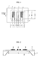
- Fig. 1 top view
- Fig. 2 sectional view
- electrical insulating film (supporting film) 6 is formed on a front side (top face) of a flat substrate 1 of silicon.
- the flat substrate 1 has a thermal insulating area (thermal insulator) 2 as a space (cavity) made by etching its reverse side (bottom face).
- the thermal insulating area 2 is defined by the bottom face of the flat substrate 1 and the electrical insulating film 6; and the space below the insulating film 6 of the thermal insulating area 2 is a cavity.
- the thermal insulating area 2 is rectangular as indicated by broken lines in Fig. 1, where its sides parallel to the axis of air flow (indicated by the bold black arrow) are greater than its sides perpendicular to the axis.
- the flat substrate 1 has a rectangular thermal insulating area 2 whose long sides are parallel to the axis of air flow.
- a U-shaped heating resistor 4 is located almost in the center in its longitudinal direction. Made of thin polysilicon film or thin platinum film, the heating resistor 4 is heated so that the difference between its temperature and the temperature of air flow to be measured is a fixed value. At both sides (upstream and downstream of the air flow) of the heating resistor 4, resistance temperature detectors 3 and 5 are located respectively. The resistance temperature detectors 3 and 5 each take the form of a rectangle consisting of several folds of thin polysilicon film or thin platinum film.
- the respective ends of the heating resistor 4 and resistance temperature detectors 3 and 5 are connected with electrode terminals 7.
- the electrode terminals 7 are located at one end in the direction perpendicular to the axis of the air flow, on the flat substrate 1.
- the heating resistor 4 is heated so that its temperature has a fixed difference from the air temperature. As air flows, the upstream temperature of the heating resistor 4 goes down and its downstream temperature goes up.
- the resistance temperature detectors 3 and 5 detect this temperature change to measure the air flow rate. This method of air flow rate measurement is well known and its detailed description is omitted here.
- the sides of thermal insulating area 2 which are parallel to the axis of air flow are greater than its sides perpendicular to the axis. In other words, it is oblong in the axial direction of the air flow.
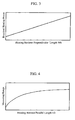
- Fig. 3 shows the relation between the perpendicular length Wh (length perpendicular to the axis of air flow) of the heating resistor 4 and the power required for the heating resistor 4 to reach a prescribed temperature level.
- the parallel sides (long sides) of the thermal insulating area 2 with respect to the axis of air flow are greater than its perpendicular sides (short sides). Therefore, according to the present invention, the power required for the heating resistor 4 can be reduced by decreasing its perpendicular length Wh while the required capacity of the heating resistor 4 is maintained.
- the y-intercept of the power versus perpendicular length relation graph (Fig. 3) corresponds to heat generation in the wiring to the heating resistor 4 or heat radiation from the heating resistor 4 to the flat substrate 1.
- Fig. 4 The relation between the parallel length Lh of the heating resistor 4 (parallel to the axis of air flow) and the air flow rate measuring range is shown in Fig. 4. As apparent from Fig. 4, the measuring range can be broadened by increasing the parallel length Lh of the heating resistor 4.
- Limitation to the air flow rate measuring range occurs for the following reason; as the rate of the air flow to be measured increases, the air flow velocity increases and thus the time period for which the air in the air flow passes over the heating resistor 4 decreases and the air in the air flow to be measured cannot be heated to a prescribed temperature level.
- This mechanism can be explained more specifically as follows.
- the air which passes over the heating resistor 4 is heated by the heating resistor 4 so that the temperature of the resistance temperature detector 5 on the downstream rises. If the air is not heated to the prescribed temperature level by the heating resistor 4, the temperature of the air flow falls after passing the heating resistor 4.
- the effect of increasing the temperature of the resistance temperature detector 5 on the downstream becomes smaller and thus the temperature difference between the resistance temperature detectors 3 and 5 which should vary according to the air flow rate becomes smaller. Consequently, with increase in the air flow rate, the output voltage might be saturated or decreased, which limits the measuring range.
- the parallel sides (long sides) of the thermal insulating area 2 with respect to the axis of air flow is greater than its perpendicular sides (short sides) and the parallel (horizontal) length of the heating resistor 4, Lh, can be increased.
- the time of the air passing over the heating resistor 4 can be sufficient and thus the measuring range can be broadened.
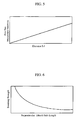
- Fig. 5 shows the relation between the flow rate measurement sensitivity and distance Ld where Ld represents the distance of the heating resistor 4 to each of the short sides of the thermal insulating area 2 in the air flow axial direction.
- Ld represents the distance of the heating resistor 4 to each of the short sides of the thermal insulating area 2 in the air flow axial direction.
- the distance Ld between the heating resistor 4 and the perpendicular sides of the thermal insulating area 2 can be increased. Therefore, the air flow rate measurement output can be increased and thus the flow rate measurement sensitivity can be improved.
- the breaking strength of the thermal insulating area (thermal insulator) 2 depends on the length W of its sides (short sides) which are perpendicular to the axis of air flow as shown in Fig. 6. As can be understood from Fig. 6, as the short side of the thermal insulating area 2 decreases, the breaking strength of the thermal insulating area 2 increases.
- the thermal insulating area 2 is rectangular and the perpendicular side with respect to the axis of air flow is the short side of the rectangle and its length W is decreased so as to increase the breaking strength of the thermal insulating area 2.
- the distance between the heating resistor 4 and the perpendicular sides of the thermal insulating area 2 (with respect to the axis of air flow) can be increased, and thus the flow rate measurement sensitivity can be improved.
- the length of the heating resistor (which is perpendicular to the axis of air flow) can be decreased so as to reduce power consumption and also the width of the heating resistor (which is parallel to the axis of air flow) can be increased so as to broaden the measuring range.
- the sides of the thermal insulating area which are perpendicular to the axis of air flow, which are the short sides of the rectangle, can be decreased so as to increase the breaking strength of the thermal insulating area.
- the inventor explored a thermal air flowmeter which saves power consumption of a heating resistor and provides a wide measuring range and a high sensitivity through a thermal insulating area with a high breaking strength.
- the relation between an index and L/W was calculated where the index is the quotient of the product of measuring range, sensitivity, and breaking strength, divided by the electric power for heating, and L represents the parallel length (parallel side, long side) of the thermal insulating area 2 with respect to the axis of air flow and W represents its perpendicular length (perpendicular side, short side).
- L represents the parallel length (parallel side, long side) of the thermal insulating area 2 with respect to the axis of air flow
- W represents its perpendicular length (perpendicular side, short side).
- the product of parallel length L and perpendicular length W namely the area of the thermal insulating area 2
- the parallel length (width) Lh of the heating resistor 4 and the distance Ld between the heating resistor 4 and the perpendicular sides of the thermal insulating area 2 are in proportion to the parallel length L of the thermal insulating area 2.
- Fig. 7 shows the result of calculation based on these conditions.
- the index product of measuring range, sensitivity, and breaking strength, divided by required electric power
- the long-to-short side ratio L/W parallel length L to perpendicular length W of the thermal insulating area 2
- Ld/W Ld/W
- Ld represents the distance Ld between the heating resistor 4 and the perpendicular sides of the thermal insulating area 2
- W the perpendicular length of the area
- Fig. 8 is a top view showing a thermal air flowmeter according to the second embodiment of the present invention.
- Fig. 8 the elements designated with the same reference numerals as those shown in Fig. 1 are elements equivalent to those in Fig. 1.
- a pair of resistance temperature detectors 3a and 3b and a pair of resistance temperature detectors 5a and 5b are provided on both sides of the heating resistor 4 respectively.
- Located on the flat substrate (silicon substrate) 1 are a resistor 10 connected in series with the heating resistor 4, a resistor 11 for measuring the air temperature and a resistor 12 connected in series with the resistor 11.
- the resistors 11 and 12 are exposed to the air flow to be measured on the flat substrate 1 in a way that their resistance values vary depending on the air temperature of the air flow.
- the heating resistor 4 and resistor 10 have the same line width so that their specific resistances do not change with patterning or etching. Likewise, the resistors 11 and 12 have the same line with so that their specific resistances do not change with patterning or etching.
- the heating resistor 4, resistance temperature detectors 3a, 3b, 5a, 5b and resistors 10, 11, 12 are respectively connected with electrode terminals 7 for connection with external circuitry.
- the resistance temperature detectors 3a, 3b, 5a, 5b generate heat when voltage is applied for temperature measurement. Particularly, measurement characteristics for low flow rates deteriorate when they generate heat.
- the line width (thickness) of the resistance temperature detectors 3a, 3b, 5a, 5b is smaller than that of the heating resistor 4, thereby increasing their resistance.
- Another approach to making the resistance of the resistance temperature detectors 3a, 3b, 5a, 5b high is that the resistance temperature detectors 3a, 3b, 5a, 5b and the heating resistor 4 are made of thin polysilicon film and the dose of the resistance temperature detectors 3a, 3b, 5a, 5b is smaller than the dose of the heating resistor 4.
- the temperature coefficient of the resistance temperature detectors 3a, 3b, 5a, 5b can also be increased by decreasing the dose of the thin polysilicon film for the resistance temperature detectors 3a, 3b, 5a, 5b, the temperature sensitivity can be further improved.
- FIG. 8 An example of drive circuitry for the thermal air flowmeter shown in Fig. 8 is shown in Fig. 9.
- the electric circuitry of the thermal air flowmeter 14 includes a heating resistor 4, resistance temperature detectors 3a, 3b, 5a, 5b and resistors 10, 11, 12.
- the heating resistor 4 and resistors 10, 11, 12 constitute a bridge circuit 15 and the resistance temperature detectors 3a, 3b, 5a, 5b constitute a bridge circuit 16.
- a direct-current power source 17 supplies power to the heating resistor 4 of the bridge circuit 15.
- An amplifier 18 detects the output voltage of the bridge circuit 15 and adds the voltage signal to a computing unit 19.
- the computing unit 19 performs calculation for proportional integration of the output signal from the amplifier 18 and gives the result to a PWM circuit 20.
- the PWM circuit 20 generates PWM signal depending on the output of the computing unit 19 to turn on or off a transistor 21.
- the current of the heating resistor 4 is controlled by turning on or off the transistor 21.
- a pulse generator 22 generates pulse signals to switch a switching circuit 23 to position a or b.
- the switching circuit 23 switches what is connected with the resistors 11 and 12.
- the b position of the switching circuit 23 is connected with a resistor 25 with a temperature coefficient which is different from that of the resistor 11 and 12.
- the resistors 11, 12, and 25 constitute a half-bridge circuit.
- the voltage of the half-bridge circuit which consists of the resistors 11, 12, and 25 is amplified by an amplifier 24 and sent to a sample hold circuit 26.
- the sample hold circuit 26 samples the output of the amplifier 24 according to pulse signals from the pulse generator 22.
- Power is supplied from a pulse generator 28 to the bridge circuit 16, which consists of the resistance temperature detectors 3a, 3b, 5a, 5b.
- the bridge voltage of the bridge circuit 16 is amplified by an amplifier 29 and sent to a sample hold circuit 30.
- the sample hold circuit 30 samples the output of the amplifier 29 according to pulse signals from the pulse generator 28.
- the drive circuitry of Fig. 9 is designed to measure the air flow rate through temperature control of the heating resistor 4, temperature detection of the air flow to be measured and temperature difference between the resistance temperature detectors 3a, 3b, 5a, 5b.
- the temperature of the heating resistor 4 is controlled as follows.
- the switching circuit 23 is set to the a position (closed) and the temperature of the heating resistor 4 is detected by the amplifier 18 according to the bridge voltage of the bridge circuit 15.
- the computing unit 19 performs proportional-integral compensation of the temperature signal of the heating resistor 4 as detected by the amplifier 18.
- PWM signal is obtained from the PWM circuit 20 to turn on and off the transistor 21.
- the current of the heating resistor 4 is controlled by turning on or off the transistor 21 so that its temperature is controlled.
- the air temperature of the air flow to be measured is detected as follows.
- the switching circuit 23 is set to the b position (closed) and the output voltage of the half-bridge circuit which consists of the resistors 11 and 12 (exposed to the air flow and located on the flat substrate 1) and the resistor 25 (which represents the reference resistance) is amplified by the amplifier 24 and sampled by the sample hold circuit 26.
- the air temperature is detected as the output of the sample hold circuit 26.
- the temperature difference between the resistance temperature detectors 3a, 3b, 5a, 5b is detected as follows. Pulse voltage is applied from the pulse generator 28 to the bridge circuit 16 and the bridge voltage of the bridge circuit 16 is amplified by the amplifier 29 and sampled by the sample hold circuit 30. A temperature difference, namely air flow rate, is detected as the output of the sample hold circuit 30.
- the power source for the bridge circuit 16 which consists of the resistance temperature detectors 3a, 3b, 5a, 5b, is driven according to pulse signals in this way, self-heating of the resistance temperature detectors 3a, 3b, 5a, 5b is reduced.
- self-heating of the resistance temperature detectors 3a, 3b, 5a, 5b is prevented from increasing the temperature of the thermal insulator (thermal insulating area) 2 by 20°C or more and thereby largely affecting the flow rate measurement characteristics.
- the parallel sides of the thermal insulator with respect to the axis of air flow are greater than its perpendicular sides and the same advantageous effects as in the first embodiments shown in Figs.1 and 2 can be achieved.
- Fig. 10 is a top view showing the third embodiment of the present invention.
- Fig. 10 the elements designated with the same reference numerals as those in Fig. 1 are equivalent to those in Fig. 1.
- This embodiment is different from the first embodiment (Fig. 1) in that part 2a of the thermal insulating area 2 where the heating resistor 4 lies is enlarged in the direction perpendicular to the axis of air flow (top-bottom direction in the figure).
- the thermal insulating area 2 is cruciform.
- the amount of heat which is transferred from the heating resistor 4 to the flat substrate 1 perpendicularly to the axis of air flow can be decreased.
- the thermal insulator (thermal insulating area) 2 is cruciform, the perpendicular side (short side) may be small, which means that heat radiation from the heating resistor 4 to the flat substrate 1 can be reduced without deterioration in the strength of the thermal insulator 2. Even when the thermal insulator 2 is not cruciform but T-shaped, the same advantageous effect can be achieved.
- the parallel sides of the thermal insulator with respect to the axis of air flow are greater than its perpendicular sides and the same advantageous effects as in the first embodiments shown in Figs.1 and 2 can be achieved.
- Fig. 11 is a top view showing the fourth embodiment of the present invention.
- each of the resistance temperature detectors 3 and 5 consists of shorter and longer portions in the direction perpendicular to the axis of air flow. The length of the longer portions is almost equal to the length of the heating element 4a and the length of the longer portions is almost equal to the length of the heating resistor 4b.
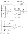
- Figs.12A, 12B, and 12C show an example of drive circuitry for the thermal air flowmeter shown in Fig. 11.
- the heating resistor 4b shorter resistor
- resistors 32 to 34 constitute a bridge circuit 31.
- the bridge voltage of the bridge circuit 31 is amplified by an amplifier 35 and supplied to the bridge circuit 31 as supply voltage.
- the heating resistor 4a (longer resistor) and resistors 37 to 39 constitute a bridge circuit 36.
- the bridge voltage of the bridge circuit 36 is amplified by an amplifier 40 and supplied through a limiting circuit 41 to the bridge circuit 36 as supply voltage.
- the resistance temperature detectors 3 and 5 and resistors 43 and 44 constitute a bridge circuit 42. Power is supplied from a direct current power source 45 to the bridge circuit 42. The bridge voltage of the bridge circuit 42 is amplified by an amplifier 46 and outputted as air flow rate measurement data.
- thermal air flowmeter When a thermal air flowmeter provides high sensitivity for low flow rates and low sensitivity but a broader measuring rage for high flow rates in this way, it is most suitable as a thermal air flow meter intended to measure an intake air flow rate in an engine.
- Fig. 15 is a top view showing the fifth embodiment of the present invention.
- Fig. 15 the elements designated with the same reference numerals as those in Fig. 1 are equivalent to those in Fig. 1.
- This embodiment is different from the embodiment in Fig. 1 in that the heating resistor 4c consists of three resistors which are connected in parallel.
- temperature unevenness may occur in the direction perpendicular to the axis of air flow, namely the temperature may be high in the center and low in the peripheral area.
- the constituent resistors of the heating resistor 4c are arranged in parallel, if the temperature of the peripheral area goes down, the resistance of the peripheral area declines and thus the current flowing through the peripheral area increases. Thus, the temperature of the peripheral area goes up and significant temperature unevenness is less likely to occur in the heating resistor 4c in the direction perpendicular to the axis of air flow.
- the peak temperature of the heating resistor 4c can be decreased by reducing the possibility of occurrence of temperature unevenness in the direction perpendicular to the axis of air flow.
- the heating resistor 4c is made of platinum or polysilicon. As the peak temperature rises, change over time occurs more easily and the resistance value changes. In the embodiment shown in Fig. 15, since the constituent resistors of the heating resistor 4c are arranged in parallel, the temperature unevenness is smaller and the peak temperature is lower.
- Fig. 16 is a sectional view showing a thermal air flowmeter according to the sixth embodiment of the present invention. In the figure, the sectional areas are not hatched for better visibility.
- This silicon member 48 increases the thermal conductivity of the heating resistor 4 and reduces temperature unevenness in the direction perpendicular to the axis of air flow.
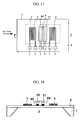
- Figs.17 and 18 show the seventh embodiment of the present invention where Fig. 17 is a top view and Fig. 18 is a sectional view taken along the line B-B of Fig. 17.
- protective film is omitted and in Fig. 8, the sectional areas are not hatched for better visibility.
- Figs.17 and 18 the elements designated with the same reference numerals as those in Figs.1 and 2 are equivalent to those in Figs.1 and 2.
- This embodiment is different from the first embodiment in Fig. 1 in that aluminum plates 50 and 51 are above the upstream side 4A and downstream side 4B of a U-shaped heating resistor 4, respectively.
- the thermal conductivity of the heating resistor 4 in the direction perpendicular to the axis of air flow is increased and temperature unevenness in the perpendicular direction is reduced.
- the aluminum plate 50 for the upstream side 4A of the U-shaped heating resistor 4 and the aluminum plate 51 for its downstream side 4B are separate from each other, the difference between the upstream and downstream sides of the heating resistor 4 changes according to change in the air flow rate more largely and more easily.
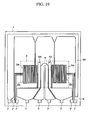
- Fig. 19 is a top view showing the eighth embodiment of the present invention.
- a pair of resistance temperature detectors 3a and 3b and a pair of resistance temperature detectors 5a and 5b are provided on both sides of the heating resistor 4 respectively.
- a shield plate (shield pattern) 54 is provided between the heating resistor 4 and the resistance temperature detectors 3a and 3b and shield plates (shield patterns) 55 and 56 are provided around the resistance temperature detectors 5a and 5b.
- the shield plates 54 and 55 are located between the heating resistor 4 and resistance temperature detectors 3a and 3b and between the heating resistor 4 and resistance temperature detectors 5a and 5b respectively and the shield plate 56 is located downstream of the resistance temperature detectors 5a and 5b.
- this structure reduces the levels of spike noise voltage which appears at both ends of the resistance temperature detectors 3a, 3b, 5a, and 5b due to electrostatic coupling of the heating resistor 4 and resistance temperature detectors 3a, 3b, 5a, and 5b.
- the eighth embodiment shown in Fig. 19 since the sides of the thermal insulating area which are parallel to the axis of air flow are greater than its perpendicular sides, the same advantageous effects as in the first embodiment shown in Figs.1 and 2 can be achieved.
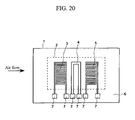
- Fig. 20 is a top view showing an air flowmeter according to the ninth embodiment of the present invention.
- the elements designated with the same reference numerals as those in Fig. 1 are equivalent to those in Fig. 1.
- This embodiment is different from the first embodiment in Fig. 1 in that resistance temperature detectors 3 and 5 are folded in a way that the total length of the sides parallel to the axis of air flow is increased.
- the resistance temperature detectors 3 and 5 are made of thin polysilicon or platinum film. Their thickness is about 1 ⁇ m. This thickness slightly affects the air flow passing over the surface of the thermal insulator 2 and changes the air flow from a laminar flow into an eddy flow.
- the resistance pattern of the resistance temperature detectors 3 and 5 is formed so that the total length of the sides parallel to the axis of air flow is increased and thus the influence of the thickness of the resistance temperature detectors 3 and 5 can be reduced.
- the air flow meter may have a silicon substrate with a triangular cross section (Fig. 16) and a cruciform insulation (Fig. 10).
- the thermal insulating area is rectangular where its sides parallel to the axis of air flow are greater than its perpendicular sides; therefore the distance between the heating element and the sides of the thermal insulating area which are perpendicular to the axis of air flow can be increased so as to improve the flow rate measurement sensitivity.
- the length of the heating resistor, which is perpendicular to the axis of air flow can be decreased so as to reduce power consumption and also the width of the heating element, which is parallel to the axis of air flow, can be increased so as to broaden the measuring range.
- the sides of the thermal insulating area which are perpendicular to the axis of air flow, which are the short sides of the rectangle, are shortened so as to increase the breaking strength of the thermal insulating area.
- Air flowmeter 1
- a thermal air flowmeter which has two types of heating resistors, wherein the perpendicular length of a first type heating resistor with respect to the axis of air flow is long and the perpendicular length of a second type heating resistor with respect to the axis of air flow is shorter than that of the first type heating resistor.
- Air flowmeter 2
- thermo air flowmeter wherein heating resistors are arranged in parallel.
- thermal air flowmeter wherein thermally conductive material is located opposite to a heating resistor.
- a thermal air flowmeter wherein a thermally conductive body is divided in the direction of air flow.
- a thermal air flowmeter wherein a wiring pattern maintained at a given voltage is provided around a resistance temperature detector or a resistance temperature detector lead wire.
- a thermal air flowmeter wherein a resistance temperature detector is a temperature-dependent resistor and located parallel to the axis of air flow.
- a thermal air flowmeter wherein voltage applied to a resistance temperature detector is pulsed.
- a thermal air flowmeter wherein a heating resistor and a resistance temperature detector are made of polysilicon film and the resistivity of the heating resistor polysilicon film is lower than the resistivity of the resistance temperature detector polysilicon film.
- a thermal air flowmeter wherein a heating resistor and a resistance temperature detector are made of polysilicon film and the heating resistor polysilicon film is thicker than the resistance temperature detector polysilicon film.
- air flowmeters 1-9 may be combined in any way in order to fit with the demands of the respective application(s). That is, air flowmeter 1 may also comprise any or all features of the air flowmeters 2-9, for example. The same applies to the other air flowmeters 2-9, of course.
Landscapes
- Physics & Mathematics (AREA)
- Fluid Mechanics (AREA)
- General Physics & Mathematics (AREA)
- Measuring Volume Flow (AREA)
Abstract
Description
More preferably, the parallel sides are 2 times, even more preferably 2.5 times longer than the perpendicular sides.
Claims (12)
- A thermal air flowmeter, comprising:wherein the length of the sides of said thermal insulating area which are substantially parallel to the axis of air flow are greater than the length of the sides thereof which are substantially perpendicular to the axis of air flow.a flat substrate (1) on the surface of which an insulating film (6) lies and a thermal insulating area (2) is provided as a substantially rectangular or cruciform space; a heating element (4) which is provided on the insulating film (6) in the thermal insulating area; and temperature detectors (3, 5) which are provided on both sides of the heating element (4) on the insulating film (6) in the thermal insulating area along the direction of air flow,
- Thermal air flowmeter according to Claim 1, characterized in that the length of the sides of said thermal insulating area which are parallel to the axis of air flow are at least 1.5 times longer than the length of the perpendicular sides thereof.
- Thermal air flowmeter according to Claim 1 or 2, characterized in that, regarding said thermal insulating area, with respect to the axis of air flow, the length between the ends of the heating resistor and the perpendicular sides is greater than the length of the perpendicular sides.
- Thermal air flowmeter according to at least one of the preceding claims, characterized in that in said thermal insulating area, the area of the heating element (4) or the heating resistor is larger than the area of the temperature detectors (3, 5) or the area of the resistance temperature detectors (3, 5).
- A thermal air flowmeter, comprising:wherein the length of the sides of said thermal insulating area which are substantially parallel to the axis of air flow are greater than the length of both sides thereof which are substantially perpendicular to the axis of air flow.a semiconductor substrate (1) on which a thermal insulating area is provided as a substantially rectangular or cruciform space;a heating resistor (4) which is provided on an insulating film (4) in the thermal insulating area; andresistance temperature detectors (3, 5) which are provided upstream and downstream of the heating resistor (4) on the insulating film (6) in the thermal insulating area,
- Thermal air flowmeter according to Claim 5, characterized in that the length of the sides of the thermal insulating area which are parallel to the axis of air flow are at least 1.5 times longer than the length of the perpendicular sides thereof.
- Thermal air flowmeter according to Claim 5 or 6, characterized in that, regarding said thermal insulating area, with respect to the axis of air flow, the length between the ends of the heating resistor and the perpendicular sides is greater than the length of the perpendicular sides.
- Thermal air flowmeter according to Claim 5, 6 or 7 characterized in that, in said thermal insulating area, the area of the heating element or the heating resistor is larger than the area of the temperature detectors (3, 5) or the area of the resistance temperature detectors.
- A thermal air flowmeter, comprising:wherein said thermal insulating area is substantially rectangular along the axis of an air flow.a silicon substrate (1) on which a thermal insulating area is provided as a substantially rectangular or cruciform space;a heating resistor (9) which is provided on an insulating film (6) in the thermal insulating area; andresistance temperature detectors (3, 5) which are provided upstream and downstream of the heating resistor (4) on the insulating film in the thermal insulating area,
- Thermal air flowmeter according to Claim 9, characterized in that the length of the sides of said thermal insulating area which are parallel to the axis of air flow are at least 1.5 times longer than the length of the perpendicular sides thereof.
- Thermal air flowmeter according to Claim 9 or 10, characterized in that, regarding said thermal insulating area, with respect to the axis of air flow, the length between the ends of the heating resistor and the perpendicular sides is greater than the length of the perpendicular sides.
- Thermal air flowmeter according to Claim 9, 10 or 11, characterized in that, in said thermal insulating area, the area of the heating element (4) or the heating resistor is larger than the area of temperature detectors (3, 5) or the area of the resistance temperature detectors.
Applications Claiming Priority (2)
| Application Number | Priority Date | Filing Date | Title |
|---|---|---|---|
| JP2003160704A JP2004361271A (en) | 2003-06-05 | 2003-06-05 | Thermal air flow meter |
| JP2003160704 | 2003-06-05 |
Publications (2)
| Publication Number | Publication Date |
|---|---|
| EP1484584A2 true EP1484584A2 (en) | 2004-12-08 |
| EP1484584A3 EP1484584A3 (en) | 2007-10-17 |
Family
ID=33157197
Family Applications (1)
| Application Number | Title | Priority Date | Filing Date |
|---|---|---|---|
| EP04013205A Withdrawn EP1484584A3 (en) | 2003-06-05 | 2004-06-04 | Thermal air flowmeter |
Country Status (4)
| Country | Link |
|---|---|
| US (1) | US7137298B2 (en) |
| EP (1) | EP1484584A3 (en) |
| JP (1) | JP2004361271A (en) |
| CN (1) | CN1573301A (en) |
Cited By (5)
| Publication number | Priority date | Publication date | Assignee | Title |
|---|---|---|---|---|
| EP1972903A3 (en) * | 2007-03-23 | 2010-06-16 | Hitachi, Ltd. | Thermal flowmeter |
| EP2233896A1 (en) * | 2009-03-24 | 2010-09-29 | Hitachi Automotive Systems, Ltd. | Thermal-type flowmeter |
| EP2357452A1 (en) * | 2006-02-03 | 2011-08-17 | Hitachi Ltd. | Thermal type flow sensor |
| EP1870681A3 (en) * | 2006-06-21 | 2013-02-27 | Hitachi, Ltd. | Thermal type flow rate measuring apparatus |
| US11346696B2 (en) * | 2018-11-15 | 2022-05-31 | Denso Corporation | Flow rate measuring device |
Families Citing this family (19)
| Publication number | Priority date | Publication date | Assignee | Title |
|---|---|---|---|---|
| AU2002952330A0 (en) * | 2002-10-29 | 2002-11-14 | Hybrid Electronics Australia Pty. Ltd | Flow transducer |
| JP4292026B2 (en) * | 2003-05-30 | 2009-07-08 | 株式会社日立製作所 | Thermal flow sensor |
| US7631555B2 (en) * | 2003-11-20 | 2009-12-15 | Hitachi, Ltd. | Thermal flowmeter for measuring a flow rate of fluid |
| JP4881554B2 (en) * | 2004-09-28 | 2012-02-22 | 日立オートモティブシステムズ株式会社 | Flow sensor |
| DE102005028143B4 (en) * | 2005-06-17 | 2025-08-14 | Robert Bosch Gmbh | Thermal air mass meter with low contamination sensitivity |
| JP4479744B2 (en) * | 2007-04-27 | 2010-06-09 | 株式会社デンソー | Flow measuring device |
| JP4836864B2 (en) * | 2007-05-16 | 2011-12-14 | 日立オートモティブシステムズ株式会社 | Thermal flow meter |
| JP5082915B2 (en) * | 2008-02-21 | 2012-11-28 | 株式会社デンソー | Air flow sensor |
| JP2011012593A (en) * | 2009-07-01 | 2011-01-20 | Hitachi Automotive Systems Ltd | Control device for internal combustion engine |
| CN101995279B (en) * | 2009-08-10 | 2012-07-18 | 上海捷程机电有限公司 | Thermal flow sensor |
| BR112012016483B1 (en) | 2010-01-06 | 2019-09-17 | Koninklijke Philips N.V | SYSTEM FOR MEASURING SPEED OF A FLUID CURRENTING A FLOW CHANNEL |
| US20110228803A1 (en) * | 2010-03-19 | 2011-09-22 | Finisar Corporation | Vcsel with integral resistive region |
| WO2012049742A1 (en) * | 2010-10-13 | 2012-04-19 | 日立オートモティブシステムズ株式会社 | Flow sensor and production method therefor, and flow sensor module and production method therefor |
| JP5220955B2 (en) * | 2010-10-13 | 2013-06-26 | 日立オートモティブシステムズ株式会社 | Flow sensor |
| JP5456815B2 (en) * | 2010-10-13 | 2014-04-02 | 日立オートモティブシステムズ株式会社 | Flow sensor and manufacturing method thereof |
| CN102491260A (en) * | 2011-12-31 | 2012-06-13 | 上海先进半导体制造股份有限公司 | Method for manufacturing flow sensor by etch self-stopping technology |
| JP2013033057A (en) * | 2012-10-04 | 2013-02-14 | Denso Corp | Flow sensor |
| EP3002564A1 (en) * | 2014-10-01 | 2016-04-06 | Siemens Schweiz AG | Air flow detection device |
| CN113532561A (en) * | 2020-04-16 | 2021-10-22 | 纬湃汽车电子(长春)有限公司 | Gas flow sensor |
Family Cites Families (16)
| Publication number | Priority date | Publication date | Assignee | Title |
|---|---|---|---|---|
| US4501144A (en) * | 1982-09-30 | 1985-02-26 | Honeywell Inc. | Flow sensor |
| JPH0663798B2 (en) * | 1986-05-09 | 1994-08-22 | 日本電装株式会社 | Thermal flow sensor |
| JPS63177023A (en) * | 1987-01-19 | 1988-07-21 | Nippon Soken Inc | Flow rate sensor |
| JPH0612493Y2 (en) * | 1988-10-18 | 1994-03-30 | 山武ハネウエル株式会社 | Micro bridge flow sensor |
| JP3175887B2 (en) * | 1992-10-27 | 2001-06-11 | 株式会社半導体エネルギー研究所 | measuring device |
| JP3366818B2 (en) | 1997-01-16 | 2003-01-14 | 株式会社日立製作所 | Thermal air flow meter |
| WO1998036247A1 (en) * | 1997-02-14 | 1998-08-20 | Fraunhofer-Gesellschaft zur Förderung der angewandten Forschung e.V. | Flow sensor component |
| JP2000283813A (en) * | 1999-03-29 | 2000-10-13 | Omron Corp | Thermal flow sensor |
| JP3687724B2 (en) * | 1999-04-15 | 2005-08-24 | オムロン株式会社 | Heater for flow meter |
| JP3484372B2 (en) * | 1999-06-10 | 2004-01-06 | 三菱電機株式会社 | Thermal flow sensor |
| US6579612B1 (en) * | 1999-06-24 | 2003-06-17 | International Business Machines Corporation | Magnetostrictive sensor structure |
| CH695166A5 (en) * | 2000-04-25 | 2005-12-30 | Sensirion Ag | Method and apparatus for measuring the flow of a liquid. |
| WO2001088486A1 (en) * | 2000-05-19 | 2001-11-22 | Mitsubishi Denki Kabushiki Kaisha | Heat-sensitive type flow rate detecting element and holder therefor |
| JP2001349761A (en) * | 2000-06-09 | 2001-12-21 | Yazaki Corp | Flow rate sensor and manufacturing method thereof |
| JP3658321B2 (en) | 2000-12-28 | 2005-06-08 | オムロン株式会社 | Flow sensor and manufacturing method thereof |
| JP3454265B2 (en) * | 2002-02-06 | 2003-10-06 | 三菱電機株式会社 | Thermal flow sensor |
-
2003
- 2003-06-05 JP JP2003160704A patent/JP2004361271A/en active Pending
-
2004
- 2004-05-20 CN CN200410045806.9A patent/CN1573301A/en active Pending
- 2004-06-04 EP EP04013205A patent/EP1484584A3/en not_active Withdrawn
- 2004-06-04 US US10/860,326 patent/US7137298B2/en not_active Expired - Fee Related
Cited By (6)
| Publication number | Priority date | Publication date | Assignee | Title |
|---|---|---|---|---|
| EP2357452A1 (en) * | 2006-02-03 | 2011-08-17 | Hitachi Ltd. | Thermal type flow sensor |
| EP1870681A3 (en) * | 2006-06-21 | 2013-02-27 | Hitachi, Ltd. | Thermal type flow rate measuring apparatus |
| EP1972903A3 (en) * | 2007-03-23 | 2010-06-16 | Hitachi, Ltd. | Thermal flowmeter |
| EP2233896A1 (en) * | 2009-03-24 | 2010-09-29 | Hitachi Automotive Systems, Ltd. | Thermal-type flowmeter |
| US8186213B2 (en) | 2009-03-24 | 2012-05-29 | Hitachi Automotive Systems, Ltd. | Thermal-type flowmeter |
| US11346696B2 (en) * | 2018-11-15 | 2022-05-31 | Denso Corporation | Flow rate measuring device |
Also Published As
| Publication number | Publication date |
|---|---|
| JP2004361271A (en) | 2004-12-24 |
| US20040244479A1 (en) | 2004-12-09 |
| CN1573301A (en) | 2005-02-02 |
| US7137298B2 (en) | 2006-11-21 |
| EP1484584A3 (en) | 2007-10-17 |
Similar Documents
| Publication | Publication Date | Title |
|---|---|---|
| US7137298B2 (en) | Thermal air flowmeter | |
| US4501144A (en) | Flow sensor | |
| US4478076A (en) | Flow sensor | |
| US4651564A (en) | Semiconductor device | |
| KR100488213B1 (en) | Thermal Air Flow Meter | |
| CA1196796A (en) | Semiconductor flow sensor | |
| EP2339334B1 (en) | Thermal gas sensor | |
| US4912975A (en) | Direct-heated flow measuring apparatus having improved response characteristics | |
| JPH0476412B2 (en) | ||
| JP4157034B2 (en) | Thermal flow meter | |
| US4831876A (en) | Measurement probe | |
| EP1870681B1 (en) | Thermal type flow rate measuring apparatus | |
| US5465618A (en) | Thermal flow sensor and heat-sensitive resistor therefor | |
| US6745625B2 (en) | Fluid flow rate measuring apparatus | |
| US7287424B2 (en) | Thermal type flow measurement apparatus having asymmetrical passage for flow rate measurement | |
| JP3193872B2 (en) | Thermal air flow meter | |
| EP0134859A1 (en) | Fluid flow sensors | |
| US20040261521A1 (en) | Flow sensor having two heating resistors | |
| JPH102773A (en) | Thermal air flow meter | |
| US6250150B1 (en) | Sensor employing heating element with low density at the center and high density at the end thereof | |
| JPH1062220A (en) | Thermal air flow meter | |
| JPH09126850A (en) | Sensor for measuring mass flow rate of fluid medium by principle of resistance wire anemometer | |
| JPH0428020Y2 (en) | ||
| JP3570659B2 (en) | Thermal flow sensor | |
| CA1220359A (en) | Flow sensor |
Legal Events
| Date | Code | Title | Description |
|---|---|---|---|
| PUAI | Public reference made under article 153(3) epc to a published international application that has entered the european phase |
Free format text: ORIGINAL CODE: 0009012 |
|
| AK | Designated contracting states |
Kind code of ref document: A2 Designated state(s): AT BE BG CH CY CZ DE DK EE ES FI FR GB GR HU IE IT LI LU MC NL PL PT RO SE SI SK TR |
|
| AX | Request for extension of the european patent |
Extension state: AL HR LT LV MK |
|
| PUAL | Search report despatched |
Free format text: ORIGINAL CODE: 0009013 |
|
| AK | Designated contracting states |
Kind code of ref document: A3 Designated state(s): AT BE BG CH CY CZ DE DK EE ES FI FR GB GR HU IE IT LI LU MC NL PL PT RO SE SI SK TR |
|
| AX | Request for extension of the european patent |
Extension state: AL HR LT LV MK |
|
| STAA | Information on the status of an ep patent application or granted ep patent |
Free format text: STATUS: THE APPLICATION HAS BEEN WITHDRAWN |
|
| 18W | Application withdrawn |
Effective date: 20080327 |