JP2004361271A - Thermal type air flowmeter - Google Patents
Thermal type air flowmeter Download PDFInfo
- Publication number
- JP2004361271A JP2004361271A JP2003160704A JP2003160704A JP2004361271A JP 2004361271 A JP2004361271 A JP 2004361271A JP 2003160704 A JP2003160704 A JP 2003160704A JP 2003160704 A JP2003160704 A JP 2003160704A JP 2004361271 A JP2004361271 A JP 2004361271A
- Authority
- JP
- Japan
- Prior art keywords
- air flow
- heat insulating
- heating resistor
- insulating region
- temperature
- Prior art date
- Legal status (The legal status is an assumption and is not a legal conclusion. Google has not performed a legal analysis and makes no representation as to the accuracy of the status listed.)
- Pending
Links
Images


Classifications
-
- G—PHYSICS
- G01—MEASURING; TESTING
- G01F—MEASURING VOLUME, VOLUME FLOW, MASS FLOW OR LIQUID LEVEL; METERING BY VOLUME
- G01F7/00—Volume-flow measuring devices with two or more measuring ranges; Compound meters
-
- G—PHYSICS
- G01—MEASURING; TESTING
- G01F—MEASURING VOLUME, VOLUME FLOW, MASS FLOW OR LIQUID LEVEL; METERING BY VOLUME
- G01F1/00—Measuring the volume flow or mass flow of fluid or fluent solid material wherein the fluid passes through a meter in a continuous flow
- G01F1/68—Measuring the volume flow or mass flow of fluid or fluent solid material wherein the fluid passes through a meter in a continuous flow by using thermal effects
- G01F1/684—Structural arrangements; Mounting of elements, e.g. in relation to fluid flow
- G01F1/688—Structural arrangements; Mounting of elements, e.g. in relation to fluid flow using a particular type of heating, cooling or sensing element
- G01F1/69—Structural arrangements; Mounting of elements, e.g. in relation to fluid flow using a particular type of heating, cooling or sensing element of resistive type
- G01F1/692—Thin-film arrangements
-
- G—PHYSICS
- G01—MEASURING; TESTING
- G01F—MEASURING VOLUME, VOLUME FLOW, MASS FLOW OR LIQUID LEVEL; METERING BY VOLUME
- G01F1/00—Measuring the volume flow or mass flow of fluid or fluent solid material wherein the fluid passes through a meter in a continuous flow
- G01F1/68—Measuring the volume flow or mass flow of fluid or fluent solid material wherein the fluid passes through a meter in a continuous flow by using thermal effects
- G01F1/696—Circuits therefor, e.g. constant-current flow meters
- G01F1/698—Feedback or rebalancing circuits, e.g. self heated constant temperature flowmeters
- G01F1/6986—Feedback or rebalancing circuits, e.g. self heated constant temperature flowmeters with pulsed heating, e.g. dynamic methods
Abstract
Description
【0001】
【発明の属する技術分野】
本発明は加熱制御される発熱体の上流側と下流側の温度差によって内燃機関の吸入空気などの空気流量を計測する熱式空気流量計に関する。
【0002】
【従来の技術】
【特許文献1】特開2002−202168号公報
【特許文献2】特許第3366818号公報
一般に、自動車などの内燃機関の吸入空気量を計測する空気流量計としては、加熱制御される発熱体(発熱抵抗体)の放熱量によって流量を計測するものや、発熱体の上流側と下流側の温度差によって流量を計測する熱式空気流量計が知られている。温度差によって流量を計測する熱式空気流量計は温度差方式と称されている。
【0003】
温度差方式の熱式空気流量計は平板状基板(シリコン基板などの半導体基板)の表面(上面)に電気絶縁膜(支持膜)を設け、この絶縁膜に発熱体(発熱抵抗体)を形成し発熱体の両側(空気流の上流側と下流側)に測温体(測温抵抗体、熱電対など)を形成している。平板状基板は発熱体や測温体を覆うように保護膜で被覆されている。
【0004】
ところで、発熱体が形成される平板状基板には発熱体との熱絶縁を図るためにエッジングにより空洞を穿設して空間の熱絶縁領域を構成している。従来、空間熱絶縁領域は略正方形に形成している。このことは、例えば、上記特許文献1、2に記載されている。
【0005】
【発明が解決しようとする課題】
従来技術は平板状基板に形成する熱絶縁領域を略正方形にしている。熱絶縁領域を形成された平板状基板の熱絶縁部は厚さ数ミクロンの薄膜の電気絶縁膜(ダイヤフラム)で構成されるため、略正方形では強度の観点から熱絶縁部の面積の大きさが制限される。例えば、空気に埃などの粒子が混ざっていると、この埃が熱絶縁部に衝突して厚さ数ミクロンの薄膜を破壊する。熱絶縁領域の大きさが制限されると空気流量測定の感度を向上させることができず、その上、発熱体の消費電力を低減できないと共に測定範囲を大きくできないという問題点を有する。
【0006】
本発明の目的は空気流量測定の感度を向上させ、発熱体の消費電力を低減できると共に測定範囲を大きくすることができる熱式尾空気流量計を提供することにある。
【0007】
【課題を解決するための手段】
本発明の特徴とするところは、平板状基板に構成されている矩形状空間の熱絶縁領域の絶縁膜に発熱体と発熱体の上流側および下流側に2つの測温体とを形成し、矩形状空間の熱絶縁領域が空気流の軸線方向と平行辺の長さが軸線方向と垂直辺の長さより大きく構成されていることにある。
【0008】
換言すると、本発明は平板状基板に空気流の軸線方向に長方形の熱絶縁領域を構成し、この長方形熱絶縁領域の絶縁膜に発熱体と2つの測温体を形成したものである。
【0009】
本発明の望ましい熱絶縁領域は空気流の軸線方向と平行辺の長さが垂直辺の1.5倍以上にして構成される。
【0010】
本発明は熱絶縁領域における空気流の軸線方向と平行辺が垂直辺の長さより大きくしており、発熱体と熱絶縁領域における空気流の軸線方向と垂直辺までの間隔(距離)を大きくとれるので流量測定感度を向上させることができる。また、発熱体の空気流軸線方向と垂直方向の長さを短くできるので消費電力を低減でき、発熱体の空気流軸線方向と平行方向の幅を大きくとれるので測定範囲を大きくすることができる。
【0011】
【発明の実施の形態】
以下、本発明の実施の形態について図面を参照して説明する。
【0012】
図1、2に本発明の第1の実施例を示す。図1は第1の実施例の平面図で、図2は図1のA−A断面図である。なお、図1、2において保護膜は図示を省略しており、また、図2は見易くするために断面を示すハッチングを省略している。図1、2において、シリコンを材料にした平板状基板1の表面(上面)には電気絶縁膜(支持膜)6が形成配置されている。平板状基板1は裏面(下面)からエッチングした空間(空洞)の熱絶縁領域(熱絶縁部)2が構成されている。空間熱絶縁領域2は平板状基板1の下面から電気絶縁膜6の境界まで形成され、熱絶縁領域2の絶縁膜6の下部が空間になる。
【0013】
熱絶縁領域2は図1に破線で示すように矩形状で黒塗り矢印で示す空気流の軸線方向と平行辺の長さが軸線方向と垂直辺の長さより大きく構成されている。換言すると、平板状基板1は空気流の軸線方向に長方形の熱絶縁領域2が構成されている。
【0014】
長方形熱絶縁領域2の絶縁膜6には長手方向の略中央部にコ字型の発熱抵抗体4が形成されている。発熱抵抗体4は測定空気流の温度と一定温度差になるように加熱され、ポリシリコン薄膜や白金薄膜で作成される。発熱抵抗体4の両側(空気流の上流側と下流側)に測温抵抗体3,5が形成されている。測温抵抗体3,5は矩形状に複数回折曲して構成され、ポリシリコン薄膜や白金薄膜で作成される。
【0015】
発熱抵抗体4、測温抵抗体3,5はその両端を外部回路と接続する電極端子7に接続されている。複数の電極端子7は平板状基板1の空気流軸線方向に対する垂直方向の一方端に配設されている。
【0016】
この構成において、発熱抵抗体4を空気温度と一定温度差に成るように加熱しておき、空気が流れると発熱抵抗体4の上流側の温度が低下し下流側の温度が上昇することを利用して、この温度の変化を測温抵抗体3,5により検出して空気流量を測定する。このような空気流量測定は良く知られているので詳細説明を省略する。
【0017】
さて、本発明においては熱絶縁領域2が空気流の軸線方向と平行辺の長さを軸線方向と垂直辺の長さより大きく構成されている。つまり、空気流の軸線方向に長方形に構成されている。発熱抵抗体4の空気流軸線方向と垂直方向の長さ(垂直方向長)Whと発熱抵抗体4を所定温度まで発熱させるために必要な電力(発熱電力)は図3に示すように表される。
【0018】
図3から明らかなように、発熱抵抗体4の垂直方向長Whを短くするほど発熱抵抗体4に必要な電力を低減することができる。これは発熱抵抗体4によって暖める空気の量、つまり、発熱抵抗体4の上を通過する空気の量が垂直方向長Whに比例するためである。
【0019】
本発明は熱絶縁領域2の空気流軸線方向と平行辺(長辺)を垂直辺(短辺)より大きくしている。したがって、本発明は発熱抵抗体4の容量を確保した上で垂直方向長Whを小さくでき発熱抵抗体4に必要な電力を低減することができる。なお、切片の部分は発熱抵抗体4への配線の発熱や発熱抵抗体4から平板状基板1への放熱によって生じる。
【0020】
また、発熱抵抗体4の空気流軸線方向と平行方向の長さ(平行方向長)Lhと空気流量の測定範囲は図4に示すように表される。図4から明らかなように発熱抵抗体4の平行方向長Lhを大きくすることによって測定範囲を拡大させることができる。
【0021】
空気流量の測定範囲の制限は測定空気流量が増加するに伴い測定する空気流の流速が増加することから測定する空気流の空気が発熱抵抗体4の上を通過する時間が減少し、測定する空気流の空気を所定の温度まで過熱できなくなることにより生じる。
【0022】
具体的に説明すると、発熱抵抗体4の上を通過する空気を発熱抵抗体4で暖めて下流側の測温抵抗体5の温度を上昇させている。発熱抵抗体4によって空気を所定温度まで過熱できないと、発熱抵抗体4を通過後の空気流の温度が低下する。下流側の測温抵抗体5の温度を上昇させる効果が小さくなるために空気流量に応じて変化していた測温抵抗体3,5の温度差が小さくなる。このため、空気量が多くなると、出力は飽和したりあるいは減少することになり測定範囲が制限される。
【0023】
本発明は熱絶縁領域2の空気流軸線方向と平行辺(長辺)を垂直辺(短辺)より大きくしており、発熱抵抗体4の水平方向長Lhを大きくできる。したがって、空気流量の増加に伴い流速が増加しても発熱抵抗体4の上を通過する空気の通過時間を確保でき、測定範囲を大きくできる。
【0024】
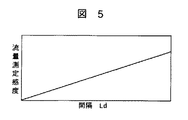
次に、流量測定感度は発熱抵抗体4と熱絶縁領域2の空気流軸線方向の垂直辺(短辺)までの間隔Ldと図5に示すような関係になる。図5から明らかなように、間隔Ldを長くすることによって空気量の対する流量測定出力(測温抵抗体3,5の温度差)を大きくすることができる。これは、熱絶縁領域2の上を通過する空気の時間が長くなることによって、熱絶縁領域2と空気の間での熱のやり取りの総量が増加することで生じる。
【0025】
本発明は熱絶縁領域2の空気流軸線方向と平行辺を垂直辺より大きくしており、発熱抵抗体4と熱絶縁領域2の垂直辺までの間隔Ldを長くできる。したがって、空気量の対する流量測定出力を大きくすることができ流量測定感度を向上させることが可能になる。
【0026】
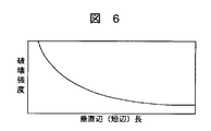
また、熱絶縁領域2における絶縁膜6の周囲を平板状基板1に固定した熱式空気流計では、熱絶縁領域(熱絶縁部)2の破壊強度が図6に示すように熱絶縁部2の空気流軸線方向の垂直辺(短辺)の長さWによって決まる。図6から明らかなように熱絶縁部2の短辺を短くすると熱絶縁部2の破壊強度が増加する。
【0027】
本発明は熱絶縁領域2を長方形にし、空気流軸線方向との垂直辺を短辺にして長さWを小さくしており、熱絶縁部2の破壊強度を増加させることができる。
【0028】
このように本発明は熱絶縁領域における空気流軸線方向と平行辺を垂直辺より大きくしており、発熱抵抗体と熱絶縁領域における空気流の軸線方向と垂直辺までの間隔(距離)を大きくとれるので流量測定感度を向上させることができる。また、発熱抵抗体の空気流軸線方向と垂直方向の長さを短くできるので消費電力を低減でき、発熱体の空気流軸線方向と平行方向の幅を大きくとれるので測定範囲を大きくすることができる。
【0029】
その上、熱絶縁領域の空気流軸線方向との垂直辺を短辺にして長さを小さくしており、熱絶縁領域の破壊強度を増加させることができる。
【0030】
以上説明したことに基づいて発熱抵抗体を発熱させるための電力が小さく、測定範囲が広く、感度が高く、かつ熱絶縁領域の破壊強度が高い熱式空気流量計を検討する。
【0031】
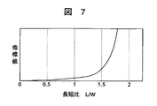
このために、測定範囲と感度と破壊強度の積を発熱電力で割った値(指標値)と熱絶縁部2の空気流軸線方向と平行方向長(平行辺、長辺)Lと垂直方向長(垂直辺、短辺)Wの比(長方形の長短比)L/Wの関係を求めてみる。なお、平行方向長Lと垂直方向長Wの積、つまり熱絶縁部2の面積を一定とし、発熱抵抗体4の平行方向長(幅)Lhと発熱抵抗体4から熱絶縁部2の垂直辺までの距離(間隔)Ldは熱絶縁部2の平行方向長Lに比例するものとしている。
【0032】
このような条件で求めた計算結果を図7に示す。図7に示すように長短比L/Wが1を超えると、測定範囲と感度と破壊強度の積を必要電力で割った値が急激に増加している。つまり、発熱抵抗体4を発熱させるための電力が小さく、空気流量の測定範囲が広く、空気流量に対する感度が高く、熱絶縁部2の破壊強度が高い熱式空気流量計を得るためには、熱絶縁部2の平行水平方向長Lと垂直方向長Wの長短比L/Wを1以上、望ましくは1.5以上にすることが非常に有効であることが判る。
【0033】
また、この関係は発熱抵抗体4から熱絶縁部2の垂直辺までの距離Ldと熱絶縁部2の垂直方向長Wの関係でも書き表すこともでき、この場合にはLd/Wを1以上にすると非常に有効となる。
【0034】
図8に本発明の第2の実施例を示す。図8は第2の実施例の熱式空気流量計の平面図である。
【0035】
図8において図1と同一符号は相当物を示し、発熱抵抗体4の両側にそれぞれ一対の測温抵抗体3a、3bと測温抵抗体5a、5bが形成されている。また、平板状基板(シリコン基板)1には発熱抵抗体4に直列接続された抵抗体10、空気の温度を測定する抵抗体11、抵抗体11に直列接続された抵抗体12が形成されている。抵抗体11、12は測定空気流の空気温度に応じて抵抗値が変化するように、測定空気流に露出して平板状基板1に形成されている。
【0036】
発熱抵抗体4と抵抗体10は線幅を同一に形成して比抵抗がパターン二ングやエッチングによって変化しないようにしている。同様に、抵抗体11と抵抗体12も線幅を同一に形成してパターン二ングやエッチングによって比抵抗が変化しないようにしている。発熱抵抗体4、測温抵抗体3a、3b、5a、5b,抵抗体10、11、12はそれぞれ外部回路と接続する電極端子7に接続されている。
【0037】
この構成において、測温抵抗体3a、3b、5a、5bは温度を測定するために電圧を印加されて発熱する。測温抵抗体3a、3b、5a、5bの発熱によって、特に低流量側の特性が悪化する。
【0038】
図8に示す実施例ではこれを防ぐために、測温抵抗体3a、3b、5a、5bは線幅(厚み)を発熱抵抗体4より薄く形成し比抵抗を高くして高抵抗にしている。
【0039】
なお、測温抵抗体3a、3b、5a、5bを高抵抗にするには測温抵抗体3a、3b、5a、5bと発熱抵抗体4をポリシリコン薄膜で構成し、測温抵抗体3a、3b、5a、5bのドーズ量を発熱抵抗体4のドーズ量よりも少なくしても行える。この場合、測温抵抗体3a、3b、5a、5bを構成するポリシリコン薄膜のドーズ量を減らすことによって、測温抵抗体3a、3b、5a、5bの温度係数を増加させることもできるので温度検出の感度を更によくすることが可能になる。
【0040】
図8に示す熱式空気流量計の駆動回路の一例を図9に示す。
【0041】
図9において熱式空気流量計14の電気回路は発熱抵抗体4、測温抵抗体3a、3b、5a、5b、抵抗体10、11、12によって構成される。発熱抵抗体4と抵抗体10、11、12でブリッジ回路15を構成し、また、測温抵抗体3a、3b、5a、5bでブリッジ回路16を構成する。
【0042】
直流電源17はでブリッジ回路15の発熱抵抗体4に電力を供給する。比較器18はブリッジ回路15の出力電圧を検出し演算器19に加える。演算器19は比較器18の出力信号を比例積分演算しPWM回路20に与える。PWM回路20は演算器19の出力に応じたPWM信号を発生しトランジスタ21をオンオフ制御する。トランジスタ21のオンオフによって発熱抵抗体4の電流が制御される。
【0043】
パルス発生回路22はパルス信号を発生して切替回路23をa側とb側にスイッチングする。切替回路23は抵抗体11、12の接続先を切替える。切替回路23のb側には抵抗体11、15と異なる温度係数を持つ抵抗体25が接続されている。抵抗体11、15と抵抗体25でハーフブリッジを構成する。
【0044】
抵抗体11、15と抵抗体25で構成されるハーフブリッジの電圧は増幅器24で増幅されサンプルホールド回路26に入力される。サンプルホールド回路26はパルス発生回路22のパルス信号によって増幅器24の出力をサンプリングする。
【0045】
測温抵抗体3a、3b、5a、5bで構成されるブリッジ回路16はパルス発生回路28から電力を供給される。ブリッジ回路16のブリッジ電圧は増幅器24で増幅されサンプルホールド回路30に取込まれる。サンプルホールド回路30はパルス発生回路28のパルス信号によって増幅器24の出力をサンプリングする。
【0046】
図9の駆動回路は発熱抵抗体4の温度制御、測定空気流の温度検出および感温抵抗体3a、3b、5a、5bの温度差で空気流量を行うようになっている。
発熱抵抗体4の温度制御は切替回路23をa側に閉路し、発熱抵抗体4の温度をブリッジ回路15のブリッジ電圧により比較器18で検出する。比較器18で検出された発熱抵抗体4の温度信号を演算器19で比例積分補償してPWM回路20からPWM信号を得てトランジスタ21をオンオフ制御する。発熱抵抗体4はトランジスタ21のオンオフにより電流を制御され、温度制御される。
【0047】
なお、トランジスタ21をオンオフ制御しているのでトランジスタ21の自己発熱を低減させている。
【0048】
次に、測定空気流の空気温度検出は切替回路23をb側に閉路し、測定空気流に露出して平板状基板1に形成された抵抗体11、12と基準抵抗である抵抗体25によって構成されるハーフブリッジの出力電圧を増幅器24で増幅してサンプルホールド回路26でサンプリングする。サンプルホールド回路26の出力として空気温度が検出される。
【0049】
このように、切替回路23を用いて空気温度を検出することによって、平板状基板1に空気流の空気の温度を検出ための特別な回路素子を必要とせずに空気流の空気温度を検出することができる。
【0050】
次に、感温抵抗体3a、3b、5a、5bの温度差検出はブリッジ回路16にパルス発生回路28からパルス電圧を印加してブリッジ回路16のブリッジ電圧を増幅器29で増幅してサンプルホールド回路30でサンプリングする。サンプルホールド回路30の出力として温度差つまり空気流量が検出される。
【0051】
このように感温抵抗体3a、3b、5a、5bで構成されるブリッジ回路16の電源をパルス駆動することにより感温抵抗体3a、3b、5a、5bの自己発熱を低減することができる。感温抵抗体3a、3b、5a、5bの自己発熱は直流的に電圧を印加すると、熱絶縁部2の温度を20℃以上増加させ流量測定特性に大きな影響を与えるのを防止できる。
【0052】
図8、図9に示す第2の実施例も熱絶縁部における空気流軸線方向と平行辺を垂直辺より大きくしており、図1、図2に示す第1の実施例と同様な効果を奏しえる。
【0053】
図10に本発明の第3の実施例を示す。図10は第3の実施例の平面図である。
【0054】
図10において図1と同一符号は相当物を示し、図1の実施例と異なるところは、熱絶縁領域2の発熱抵抗体4が形成される領域2aを空気流軸線方向と垂直方向(図の上下方向)に大きくしたものである。換言すると、熱絶縁領域2を十字型に構成したものである。
【0055】
図10の実施例では発熱抵抗体4から空気流軸線方向と垂直方向に伝わり平板状基板1へ伝熱する熱量を低減することができる。また、熱絶縁部(熱絶縁領域)2を十字型にすることによって垂直辺(短辺)を小さくでき熱絶縁部2の強度を損なうことなく発熱抵抗体4から平板状基板1への放熱を低減することができる。なお、熱絶縁部2の構成は十字型以外にもT字型などでも同様の効果を得ることができる。
【0056】
図10に示す第3の実施例も熱絶縁部における空気流軸線方向と平行辺を垂直辺より大きくしており、図1、図2に示す第1の実施例と同様な効果を奏しえる。
【0057】
図11に本発明の第4の実施例を示す。図11は第4の実施例の平面図である。
【0058】
図11において図1と同一符号は相当物を示し、図1の実施例と異なるところは、空気流軸線方向と垂直方向の長さが異なる2つの発熱抵抗体4a、4bを設けたことである。測温抵抗体3、5にも空気流軸線方向と垂直方向の長さが異なる部分が形成されている。測温抵抗体3、5の長さの大きい部分の長さは発熱抵抗体4aに略等しく、長さの小さい部分の長さは発熱抵抗体4bに略等しく形成されている。
【0059】
図11に示す熱式空気流量計の駆動回路の一例を図12に示す。
【0060】
図12(a)は発熱抵抗体(短い発熱抵抗体)4bと抵抗32〜34でブリッジ回路31を構成し、ブリッジ回路31のブリッジ電圧を増幅器35で増幅してブリッジ回路31に電源電圧として供給している。
【0061】
図12(b)は発熱抵抗体(長い発熱抵抗体)4aと抵抗37〜39でブリッジ回路36を構成し、ブリッジ回路36のブリッジ電圧を増幅器40で増幅し制限回路41を介してブリッジ回路36に電源電圧として供給している。
【0062】
図12(c)は感温抵抗体3,5と抵抗43,44でブリッジ回路42を構成し、ブリッジ回路42に直流電源45から給電している。ブリッジ回路42のブリッジ電圧を増幅器46で増幅して空気流量として出力する。
【0063】
図11に示す第4の実施例の熱式空気流量計を図12の駆動回路で駆動した場合の動作特性を図13により説明する。
【0064】
図12(b)に示す空気流軸線方向の垂直方向の長さが大きい発熱抵抗体4aのみを動作させた場合には、図13の特性aのように低流量側で大きな感度を示し、高流量側では飽和する。これは、発熱抵抗体4aの空気流軸線方向に垂直な方向の長さが大きいために、両側に配置される感熱抵抗体3,5に与える影響が大きいためである。一方、高流量側では制限回路42があるために発熱抵抗体4aの温度が下がり出力電圧が飽和する。
【0065】
図12(a)に示す空気流軸線方向の垂直方向の長さが小さい発熱抵抗体4bのみを動作させた場合は、特性bのように低流量での感度は小さいが大きな測定範囲を出力電圧(流量測定電圧)を得ることができる。また、発熱抵抗体4a、4bを同時に動作させた場合には特性cのように低流量側での感度が大きく、高流量側で飽和しない出力電圧を得ることができる。
【0066】
このように低流量での感度が大きく、高流量側では感度は小さいが測定範囲を広い特性はエンジンの吸入空気量の計測などに使われる熱式空気流量計として最適な特性となる。
【0067】
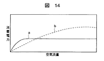
また、消費電力については、図14に示すように発熱抵抗体4bのみを動作させた場合は特性bのようになり、発熱抵抗体4aのみを動作させた場合には特性aのようになる。発熱抵抗体4aのみを動作させた場合は制限回路41により制限され、高流量における発熱抵抗体4aの消費電力を低減させることができる。なお、図11に示す第4の実施例も熱絶縁部における空気流軸線方向と平行辺を垂直辺より大きくしており、図1、図2に示す第1の実施例と同様な効果を奏しえる。
【0068】
図15に本発明の第5の実施例を示す。図15は第5の実施例の平面図である。
【0069】
図15において図1と同一符号は相当物を示し、図1の第1の実施例と異なるところは発熱抵抗体4cを3個の抵抗体で形成し、この3個の抵抗体を並列接続していることである。
【0070】
第1の実施例のような図1に示す発熱抵抗体4では発熱抵抗体4に空気流軸線方向と垂直方向に温度斑(温度不揃い)が生じ、中央部分の温度が高く周辺部分の温度が低くなることがある。図15の実施例では発熱抵抗体4cを並列構成にしているために周辺部の温度が低下すると、周辺部の抵抗値の低下によって周辺部に流れる電流が増加する。このため、周辺部の温度が上昇するので、発熱抵抗体4cに空気流軸線方向と垂直方向に大きな温度斑が生じにくくなる。
【0071】
このように、発熱抵抗体4cに空気流軸線方向と垂直方向の温度斑を低減することによって、発熱抵抗体4cのピーク温度を下げることができる。発熱抵抗体4cは白金抵抗やポリシリコンで構成されるが、ピーク温度が高くなると経時変化を生じやすくなり抵抗値が変化する。図15の実施例では発熱抵抗体4cを並列構成にすることで温度斑を低減できピーク温度を低く抑えることが可能になる。
【0072】
また、図15に示す第5の実施例も熱絶縁部における空気流軸線方向と平行辺を垂直辺より大きくしており、図1、図2に示す第1の実施例と同様な効果を奏しえる。
【0073】
図16に本発明の第6の実施例を示す。図16は第6の実施例の熱式空気流量計の断面図である。なお、図16は見易くするために断面を示すハッチングを省略している。
【0074】
図16において図1と同一符号は相当物を示し、図1の第1の実施例と異なるところは発熱抵抗体4の下部に断面三角状のシリコン部材48を設けたことである。
【0075】
このようにシリコン部材48を設けると発熱抵抗体4の部分の熱伝導性を高め、空気流軸線方向と垂直方向の温度斑を低減することができる。
【0076】
なお、図16の第6の実施例も熱絶縁部2は空気流軸線方向と平行辺を垂直辺より大きく形成しており、図1、図2に示す第1の実施例と同様な効果を奏しえる。
【0077】
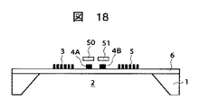
図17、図18に本発明の第7の実施例を示す。図17は第7の実施例の平面図、図18は図17のB−B断面図である。なお、図17、18において保護膜は図示を省略しており、また、図18は見易くするために断面を示すハッチングを省略している。
【0078】
図17、18において図1、2と同一符号は相当物を示し、図1の第1の実施例と異なるところはコ字型の発熱抵抗体4の上流側片4Aと下流側片4Bの上部にそれぞれアルミ板50、51を設けたことである。
【0079】
このように発熱抵抗体4の上部にアルミ板50,51を設けると発熱抵抗体4の空気流軸線方向に対して垂直方向の熱伝導性を高めて垂直方向の温度斑を低減することができる。また、コ字型の発熱抵抗体4の上流側片4Aと下流側片4Bにアルミ板50,51を別々に設けているので、発熱抵抗体4の上流側の温度と下流側の温度が空気流量の変化により大きく変化し易くなり測定範囲を拡大できる。
【0080】
また、図17,18に示す第7の実施例も熱絶縁部2における空気流軸線方向と平行辺を垂直辺より大きくしており、図1、図2に示す第1の実施例と同様な効果を奏しえる。
【0081】
図19に本発明の第8の実施例を示す。図19は第8の実施例の平面図である。
【0082】
図19において図1、図8と同一符号は相当物を示し、発熱抵抗体4の両側にそれぞれ一対の測温抵抗体3a、3bと測温抵抗体5a、5bが形成されている。また、発熱抵抗体4と測温抵抗体3a、3bの間にシールド板(シールドパターン)54が配置され、測温抵抗体5a、5bの周囲に間にシールド板(シールドパターン)55、56が形成配置されている。
【0083】
図19に本発明の第8の実施例は発熱抵抗体4と測温抵抗体3a、3bおよび測温抵抗体5a、5b間にそれぞれシールド板54,55を配置し、測温抵抗体5a、5bの下流側にシールド板56を配置している。
【0084】
このように構成すると、発熱抵抗体4をパルス駆動した時に発熱抵抗体4と測温抵抗体3a、3b、5a、5bの静電結合によって生じる測温抵抗体3a、3b、5a、5bの両端に現れるヒゲ状のノイズ電圧を低減することができる。
また、図19に示す第8の実施例も熱絶縁部2における空気流軸線方向と平行辺を垂直辺より大きくしており、図1、図2に示す第1の実施例と同様な効果を奏しえる。
【0085】
図20に本発明の第9の実施例を示す。図20は第9の実施例における空気流量計の平面図である。
【0086】
図20において図1と同一符号は相当物を示し、図1の第1の実施例と異なるところは測温抵抗体3,5の抵抗パターンを空気流軸線方向と平行方向の距離が長くなるように空気流軸線方向に折曲したことである。
【0087】
測温抵抗体3、5はポリシリコン薄膜や白金薄膜によって構成されるが、その厚みは1μm程度である。この1μmの厚みは熱絶縁部2の表面を流れる空気の流れに微妙な影響を与え、空気流を層流から乱流に変化させることになる。
【0088】
図20に示す本発明の第9の実施例は測温抵抗体3、5の抵抗パターンを空気流軸線方向と平行方向の距離が長くなるように形成しているので測温抵抗体3、5の厚みによる影響を低減できる。
【0089】
また、図20に示す第9の実施例も熱絶縁部2における空気流軸線方向と平行辺を垂直辺より大きくしており、図1、図2に示す第1の実施例と同様な効果を奏しえる。
【0090】
また、図20に示す第9の実施例も熱絶縁部2における空気流軸線方向と平行辺を垂直辺より大きくしており、図1、図2に示す第1の実施例と同様な効果を奏しえる。
【0091】
以上説明したように、本発明は熱絶縁領域における空気流の軸線方向と平行辺が垂直辺の長さより大きくし長方形にしており、発熱体と熱絶縁領域における空気流の軸線方向と垂直辺までの間隔(距離)を大きくとれるので流量測定感度を向上させることができる。また、発熱体の空気流軸線方向と垂直方向の長さを短くできるので消費電力を低減でき、発熱体の空気流軸線方向と平行方向の幅を大きくとれるので測定範囲を大きくすることができる。
【0092】
また、上述の実施例は熱絶縁領域の空気流軸線方向との垂直辺を短辺にして長さを小さくしており、熱絶縁領域の破壊強度を増加させることができる。
【0093】
なお、上述の各実施例から把握できる請求項に記載していない技術思想(発明)について下記すると次のようになる。
【0094】
【発明1】
発熱抵抗体は2種類有り、第1の発熱抵抗体は空気流軸線方向に対して垂直方向の長さが長い発熱抵抗体で、第2の発熱抵抗体は空気流に対して垂直方向の長さが第1の発熱抵抗体より短い発熱抵抗体であることを特徴とする熱式空気流量計。
【発明2】
発熱抵抗体が並列構成されていることを特徴とする熱式空気流量計。
【発明3】
熱絶縁部に熱伝導性材を発熱抵抗体に対抗するように配置したことを特徴とする熱式空気流量計。
【発明4】
熱伝導性の物体を空気流の方向に対して分割したことを特徴とする熱式空気流量計。
【発明5】
測温抵抗体あるいは測温抵抗体の引き出し配線の周囲に一定電位に保持された配線パターンを配置したことを特徴とする熱式空気流量計。
【発明6】
測温抵抗体が温度依存性を持つ抵抗体で、空気流軸線方向に平行に配置したことを特徴とする熱式空気流量計。
【発明7】
測温抵抗体に印加する電圧をパルス状にしたことを特徴とする熱式空気流量計。
【発明8】
発熱抵抗体と測温抵抗体はポリシリコン膜で形成され、発熱抵抗体のポリシリコン膜の抵抗率が測温抵抗体のポリシリコン膜の抵抗率より低いことを特徴とする熱式空気流量計。
【発明9】
発熱抵抗体と測温抵抗体はがポリシリコン膜で形成され、発熱抵抗体のポリシリコン膜の厚みが測温抵抗体のポリシリコン膜より厚いことを特徴とする熱式空気流量。
【0095】
【発明の効果】
本発明は熱絶縁領域における空気流の軸線方向と平行辺が垂直辺の長さより大きくしており、発熱体と熱絶縁領域における空気流の軸線方向と垂直辺までの間隔(距離)を大きくとれるので流量測定感度を向上させることができる。また、発熱体の空気流軸線方向と垂直方向の長さを短くできるので消費電力を低減でき、発熱体の空気流軸線方向と平行方向の幅を大きくとれるので測定範囲を大きくすることができる。
【図面の簡単な説明】
【図1】本発明の第1の実施例を示す平面図である。
【図2】図1のA−A断面図である。
【図3】本発明を説明するための特性図である。
【図4】本発明を説明するための特性図である。
【図5】本発明を説明するための特性図である。
【図6】本発明を説明するための特性図である。
【図7】本発明を説明するための特性図である。
【図8】本発明の第2の実施例を示す平面図である。
【図9】第2の実施例を動作させる駆動回路の一例構成図である。
【図10】本発明の第3の実施例を示す平面図である。
【図11】本発明の第4の実施例を示す平面図である。
【図12】第4の実施例を動作させる駆動回路の一例構成図である。
【図13】第4の実施例を説明するための特性図である。
【図14】第4の実施例を説明するための特性図である。
【図15】本発明の第5の実施例を示す平面図である。
【図16】本発明の第6の実施例を示す断面図である。
【図17】本発明の第7の実施例を示す平面図である。
【図18】図17のB−B断面図である。
【図19】本発明の第8の実施例を示す平面図である。
【図20】本発明の第9の実施例を示す平面図である。
【符号の説明】
1…平板状基板、2…熱絶縁領域(熱絶縁部)、3、5…測温抵抗体、4…発熱抵抗体、6…絶縁膜、7…端子電極、48…シリコン部材、50,51…アルミ板、54,55、56…シールド板。[0001]
TECHNICAL FIELD OF THE INVENTION
The present invention relates to a thermal air flow meter that measures an air flow rate of intake air or the like of an internal combustion engine based on a temperature difference between an upstream side and a downstream side of a heating element whose heating is controlled.
[0002]
[Prior art]
[Patent Document 1] JP-A-2002-202168
[Patent Document 2] Japanese Patent No. 3366818
Generally, an air flow meter that measures the intake air amount of an internal combustion engine of an automobile or the like measures a flow rate based on a heat release amount of a heating element (heating resistor) to be heated, or an upstream side and a downstream side of the heating element. A thermal air flow meter that measures a flow rate based on a temperature difference of the air flow is known. A thermal air flow meter that measures a flow rate based on a temperature difference is called a temperature difference method.
[0003]
In the thermal air flow meter of the temperature difference method, an electric insulating film (support film) is provided on the surface (upper surface) of a flat substrate (semiconductor substrate such as a silicon substrate), and a heating element (heating resistor) is formed on the insulating film. A temperature measuring element (temperature measuring resistor, thermocouple, etc.) is formed on both sides of the heating element (upstream and downstream of the airflow). The flat substrate is covered with a protective film so as to cover the heating element and the temperature measuring element.
[0004]
By the way, a cavity is formed by edging in the flat substrate on which the heating element is formed in order to thermally insulate the heating element from the heating element, thereby forming a heat insulating region in the space. Conventionally, the spatial heat insulating region is formed in a substantially square shape. This is described, for example, in
[0005]
[Problems to be solved by the invention]
In the prior art, the heat insulating region formed on the flat substrate is made substantially square. Since the thermal insulation part of the flat substrate on which the thermal insulation region is formed is composed of a thin electric insulation film (diaphragm) with a thickness of several microns, the area of the thermal insulation part is approximately square in view of strength. Limited. For example, if particles such as dust are mixed in the air, the dust collides with the heat insulating portion and breaks a thin film having a thickness of several microns. If the size of the heat insulating region is limited, the sensitivity of the air flow measurement cannot be improved, and furthermore, the power consumption of the heating element cannot be reduced and the measurement range cannot be increased.
[0006]
SUMMARY OF THE INVENTION It is an object of the present invention to provide a thermal tail air flow meter that can improve the sensitivity of air flow measurement, reduce the power consumption of a heating element, and increase the measurement range.
[0007]
[Means for Solving the Problems]
The feature of the present invention is that a heating element and two temperature measuring elements are formed upstream and downstream of the heating element on an insulating film in a heat insulating region of a rectangular space formed on a flat substrate, The heat insulating region of the rectangular space is configured such that the length of a side parallel to the axial direction of the air flow is longer than the length of a side perpendicular to the axial direction.
[0008]
In other words, according to the present invention, a rectangular heat insulating region is formed on the flat substrate in the axial direction of the air flow, and a heating element and two temperature measuring elements are formed on the insulating film in the rectangular heat insulating region.
[0009]
A desirable heat insulating region of the present invention is configured so that the length of a side parallel to the axial direction of the air flow is 1.5 times or more the vertical side.
[0010]
In the present invention, the side parallel to the axial direction of the air flow in the heat insulating region is longer than the length of the vertical side, and the distance (distance) between the heating element and the vertical direction to the axial direction of the air flow in the heat insulating region can be increased. Therefore, the flow measurement sensitivity can be improved. Further, since the length of the heating element in the direction perpendicular to the air flow axis can be reduced, power consumption can be reduced, and the width of the heating element in the direction parallel to the air flow axis can be increased, so that the measurement range can be increased.
[0011]
BEST MODE FOR CARRYING OUT THE INVENTION
Hereinafter, embodiments of the present invention will be described with reference to the drawings.
[0012]
1 and 2 show a first embodiment of the present invention. FIG. 1 is a plan view of the first embodiment, and FIG. 2 is a sectional view taken along line AA of FIG. In FIGS. 1 and 2, the protective film is not shown, and in FIG. 2, hatching indicating a cross section is omitted for easy viewing. 1 and 2, an electric insulating film (support film) 6 is formed and arranged on the surface (upper surface) of a
[0013]
The
[0014]
A
[0015]
Both ends of the
[0016]
In this configuration, the
[0017]
By the way, in the present invention, the length of the side parallel to the axial direction of the airflow is longer than the length of the side perpendicular to the axial direction of the
[0018]
As is clear from FIG. 3, the power required for the
[0019]
In the present invention, the side (long side) parallel to the direction of the air flow axis of the
[0020]
The length Lh (parallel direction length) of the
[0021]
The measurement range of the air flow rate is limited because the flow rate of the air flow to be measured increases as the flow rate of the measured air increases, so that the time during which the air of the air flow to be measured passes over the
[0022]
More specifically, the air passing over the
[0023]
In the present invention, the side (long side) parallel to the direction of the airflow axis of the
[0024]
Next, the flow rate measurement sensitivity has the relationship shown in FIG. 5 with the distance Ld between the
[0025]
In the present invention, the side parallel to the air flow axis direction of the
[0026]
Further, in the thermal airflow meter in which the periphery of the insulating
[0027]
According to the present invention, the
[0028]
As described above, in the present invention, the side parallel to the air flow axis direction in the heat insulating region is larger than the vertical side, and the distance (distance) between the heating resistor and the air flow axis direction in the heat insulating region and the vertical side is increased. As a result, the flow measurement sensitivity can be improved. Also, the length of the heating resistor in the direction perpendicular to the air flow axis can be shortened, so that power consumption can be reduced, and the width of the heating element in the direction parallel to the air flow axis can be increased, so that the measurement range can be increased. .
[0029]
In addition, the length of the heat insulation region is made shorter by making the side perpendicular to the direction of the airflow axis shorter, so that the breaking strength of the heat insulation region can be increased.
[0030]
On the basis of the above description, a thermal air flow meter that requires a small amount of power to generate heat from the heat generating resistor, has a wide measurement range, has high sensitivity, and has high breaking strength of the heat insulating region will be considered.
[0031]
For this purpose, a value (index value) obtained by dividing the product of the measurement range, the sensitivity and the breaking strength by the heat generation power, the length L in the direction parallel to the air flow axis direction (parallel side, long side) L and the length in the vertical direction of the
[0032]
FIG. 7 shows the calculation results obtained under such conditions. As shown in FIG. 7, when the ratio L / W exceeds 1, the value obtained by dividing the product of the measurement range, the sensitivity, and the breaking strength by the required power sharply increases. In other words, in order to obtain a thermal air flow meter that requires a small amount of electric power to generate heat from the
[0033]
This relationship can also be expressed by the relationship between the distance Ld from the
[0034]
FIG. 8 shows a second embodiment of the present invention. FIG. 8 is a plan view of the thermal air flow meter of the second embodiment.
[0035]
In FIG. 8, the same reference numerals as those in FIG. 1 denote equivalent elements, and a pair of
[0036]
The
[0037]
In this configuration, the
[0038]
In the embodiment shown in FIG. 8, in order to prevent this, the
[0039]
In order to increase the resistance of the
[0040]
FIG. 9 shows an example of a drive circuit of the thermal air flow meter shown in FIG.
[0041]
In FIG. 9, the electric circuit of the thermal air flow meter 14 includes the
[0042]
The DC power supply 17 supplies power to the
[0043]
The
[0044]
The voltage of the half bridge composed of the
[0045]
The
[0046]
The drive circuit of FIG. 9 is adapted to control the temperature of the
To control the temperature of the
[0047]
Note that self-heating of the
[0048]
Next, the air temperature of the measurement air flow is detected by closing the switching
[0049]
As described above, by detecting the air temperature using the
[0050]
Next, the temperature difference between the temperature-
[0051]
By self-pulsing the power supply of the
[0052]
In the second embodiment shown in FIGS. 8 and 9, the side parallel to the airflow axis direction in the heat insulating portion is larger than the vertical side, and the same effects as those in the first embodiment shown in FIGS. I can play.
[0053]
FIG. 10 shows a third embodiment of the present invention. FIG. 10 is a plan view of the third embodiment.
[0054]
In FIG. 10, the same reference numerals as those in FIG. 1 denote corresponding parts, and the difference from the embodiment of FIG. 1 is that the region 2a of the
[0055]
In the embodiment of FIG. 10, the amount of heat transmitted from the
[0056]
Also in the third embodiment shown in FIG. 10, the side parallel to the air flow axis direction in the heat insulating portion is made larger than the vertical side, and the same effects as in the first embodiment shown in FIGS.
[0057]
FIG. 11 shows a fourth embodiment of the present invention. FIG. 11 is a plan view of the fourth embodiment.
[0058]
In FIG. 11, the same reference numerals as those in FIG. 1 denote equivalent parts, and the point different from the embodiment of FIG. 1 is that two
[0059]
FIG. 12 shows an example of a drive circuit of the thermal air flow meter shown in FIG.
[0060]
In FIG. 12A, a
[0061]
FIG. 12B shows a
[0062]
In FIG. 12C, a
[0063]
Operational characteristics when the thermal air flow meter of the fourth embodiment shown in FIG. 11 is driven by the drive circuit of FIG. 12 will be described with reference to FIG.
[0064]
When only the heating resistor 4a having a large length in the vertical direction of the air flow axis direction shown in FIG. 12B is operated, a large sensitivity is exhibited on the low flow rate side as shown by the characteristic a in FIG. It saturates on the flow side. This is because the length of the heating resistor 4a in the direction perpendicular to the airflow axis direction is large, so that the heating resistor 4a has a large effect on the
[0065]
When only the
[0066]
As described above, the characteristic having a large sensitivity at a low flow rate and a small sensitivity at a high flow rate side, but having a wide measurement range is an optimal characteristic as a thermal air flow meter used for measurement of an intake air amount of an engine.
[0067]
In addition, the power consumption is as shown by a characteristic b when only the
[0068]
FIG. 15 shows a fifth embodiment of the present invention. FIG. 15 is a plan view of the fifth embodiment.
[0069]
In FIG. 15, the same reference numerals as those in FIG. 1 denote corresponding parts, and what differs from the first embodiment of FIG. 1 is that the
[0070]
In the
[0071]
Thus, the peak temperature of the
[0072]
Also, in the fifth embodiment shown in FIG. 15, the side parallel to the direction of the air flow axis in the heat insulating portion is made larger than the vertical side, and the same effects as those in the first embodiment shown in FIGS. I can.
[0073]
FIG. 16 shows a sixth embodiment of the present invention. FIG. 16 is a sectional view of a thermal air flow meter according to the sixth embodiment. In FIG. 16, hatching indicating a cross section is omitted for easy viewing.
[0074]
In FIG. 16, the same reference numerals as those in FIG. 1 denote corresponding parts, and the point different from the first embodiment in FIG. 1 is that a
[0075]
By providing the
[0076]
In the sixth embodiment of FIG. 16 as well, the
[0077]
17 and 18 show a seventh embodiment of the present invention. FIG. 17 is a plan view of the seventh embodiment, and FIG. 18 is a sectional view taken along line BB of FIG. 17 and 18, the protective film is not shown, and in FIG. 18, hatching showing a cross section is omitted for easy viewing.
[0078]
In FIGS. 17 and 18, the same reference numerals as those in FIGS. 1 and 2 denote corresponding parts, and the difference from the first embodiment in FIG. Are provided with
[0079]
When the
[0080]
Also, in the seventh embodiment shown in FIGS. 17 and 18, the side parallel to the direction of the air flow axis in the
[0081]
FIG. 19 shows an eighth embodiment of the present invention. FIG. 19 is a plan view of the eighth embodiment.
[0082]
In FIG. 19, the same reference numerals as those in FIGS. 1 and 8 denote equivalent elements, and a pair of
[0083]
FIG. 19 shows an eighth embodiment of the present invention in which
[0084]
With this configuration, both ends of the
Also, in the eighth embodiment shown in FIG. 19, the side parallel to the direction of the air flow axis in the
[0085]
FIG. 20 shows a ninth embodiment of the present invention. FIG. 20 is a plan view of the air flow meter according to the ninth embodiment.
[0086]
In FIG. 20, the same reference numerals as those in FIG. 1 denote corresponding parts, and the difference from the first embodiment in FIG. In the direction of the air flow axis.
[0087]
The
[0088]
In the ninth embodiment of the present invention shown in FIG. 20, the resistance patterns of the
[0089]
Also, in the ninth embodiment shown in FIG. 20, the side parallel to the airflow axis direction in the
[0090]
Also, in the ninth embodiment shown in FIG. 20, the side parallel to the airflow axis direction in the
[0091]
As described above, the present invention has a rectangular shape in which the side parallel to the axial direction of the air flow in the heat insulating region is longer than the length of the vertical side and has a rectangular shape. The distance (distance) can be made large, so that the flow rate measurement sensitivity can be improved. Further, since the length of the heating element in the direction perpendicular to the air flow axis can be reduced, power consumption can be reduced, and the width of the heating element in the direction parallel to the air flow axis can be increased, so that the measurement range can be increased.
[0092]
Further, in the above-described embodiment, the length of the heat insulating region is reduced by making the side perpendicular to the direction of the airflow axis shorter, thereby increasing the breaking strength of the heat insulating region.
[0093]
The technical ideas (inventions) not described in the claims that can be grasped from the above-described embodiments will be described below.
[0094]
There are two types of heating resistors, the first heating resistor is a heating resistor having a longer length in the direction perpendicular to the airflow axis direction, and the second heating resistor is longer in the direction perpendicular to the airflow. A thermal air flow meter, wherein the thermal air flow meter is a heating resistor shorter than the first heating resistor.
A thermal air flow meter, wherein heating resistors are configured in parallel.
A thermal air flow meter, wherein a heat conductive material is arranged in a heat insulating portion so as to oppose a heating resistor.
A thermal air flow meter wherein a thermally conductive object is divided in the direction of air flow.
A thermal air flowmeter, wherein a wiring pattern maintained at a constant potential is arranged around a temperature measuring resistor or a lead wire of the temperature measuring resistor.
A thermal air flow meter, wherein the temperature measuring resistor is a temperature-dependent resistor and is arranged in parallel with the direction of the air flow axis.
A thermal air flowmeter characterized in that the voltage applied to the resistance bulb is pulsed.
Invention 8
The thermal air flowmeter is characterized in that the heating resistor and the temperature measuring resistor are formed of a polysilicon film, and the resistivity of the polysilicon film of the heating resistor is lower than the resistivity of the polysilicon film of the temperature measuring resistor. .
Invention 9
The thermal air flow rate, wherein the heating resistor and the temperature measuring resistor are formed of a polysilicon film, and the thickness of the polysilicon film of the heating resistor is thicker than that of the temperature measuring resistor.
[0095]
【The invention's effect】
In the present invention, the side parallel to the axial direction of the air flow in the heat insulating region is longer than the length of the vertical side, and the distance (distance) between the heating element and the vertical direction to the axial direction of the air flow in the heat insulating region can be increased. Therefore, the flow measurement sensitivity can be improved. Further, since the length of the heating element in the direction perpendicular to the air flow axis can be reduced, power consumption can be reduced, and the width of the heating element in the direction parallel to the air flow axis can be increased, so that the measurement range can be increased.
[Brief description of the drawings]
FIG. 1 is a plan view showing a first embodiment of the present invention.
FIG. 2 is a sectional view taken along line AA of FIG.
FIG. 3 is a characteristic diagram for explaining the present invention.
FIG. 4 is a characteristic diagram for explaining the present invention.
FIG. 5 is a characteristic diagram for explaining the present invention.
FIG. 6 is a characteristic diagram for explaining the present invention.
FIG. 7 is a characteristic diagram for explaining the present invention.
FIG. 8 is a plan view showing a second embodiment of the present invention.
FIG. 9 is a diagram illustrating an example of a configuration of a drive circuit that operates the second embodiment.
FIG. 10 is a plan view showing a third embodiment of the present invention.
FIG. 11 is a plan view showing a fourth embodiment of the present invention.
FIG. 12 is an example configuration diagram of a drive circuit that operates the fourth embodiment.
FIG. 13 is a characteristic diagram for explaining the fourth embodiment.
FIG. 14 is a characteristic diagram for explaining the fourth embodiment.
FIG. 15 is a plan view showing a fifth embodiment of the present invention.
FIG. 16 is a sectional view showing a sixth embodiment of the present invention.
FIG. 17 is a plan view showing a seventh embodiment of the present invention.
18 is a sectional view taken along line BB of FIG.
FIG. 19 is a plan view showing an eighth embodiment of the present invention.
FIG. 20 is a plan view showing a ninth embodiment of the present invention.
[Explanation of symbols]
DESCRIPTION OF
Claims (6)
Priority Applications (4)
| Application Number | Priority Date | Filing Date | Title |
|---|---|---|---|
| JP2003160704A JP2004361271A (en) | 2003-06-05 | 2003-06-05 | Thermal type air flowmeter |
| CN200410045806.9A CN1573301A (en) | 2003-06-05 | 2004-05-20 | Thermal air flowmeter |
| US10/860,326 US7137298B2 (en) | 2003-06-05 | 2004-06-04 | Thermal air flowmeter |
| EP04013205A EP1484584A3 (en) | 2003-06-05 | 2004-06-04 | Thermal air flowmeter |
Applications Claiming Priority (1)
| Application Number | Priority Date | Filing Date | Title |
|---|---|---|---|
| JP2003160704A JP2004361271A (en) | 2003-06-05 | 2003-06-05 | Thermal type air flowmeter |
Publications (1)
| Publication Number | Publication Date |
|---|---|
| JP2004361271A true JP2004361271A (en) | 2004-12-24 |
Family
ID=33157197
Family Applications (1)
| Application Number | Title | Priority Date | Filing Date |
|---|---|---|---|
| JP2003160704A Pending JP2004361271A (en) | 2003-06-05 | 2003-06-05 | Thermal type air flowmeter |
Country Status (4)
| Country | Link |
|---|---|
| US (1) | US7137298B2 (en) |
| EP (1) | EP1484584A3 (en) |
| JP (1) | JP2004361271A (en) |
| CN (1) | CN1573301A (en) |
Cited By (9)
| Publication number | Priority date | Publication date | Assignee | Title |
|---|---|---|---|---|
| JP2006349688A (en) * | 2005-06-17 | 2006-12-28 | Robert Bosch Gmbh | Hot air mass meter reduced in vulnerability of contamination |
| JP2009198299A (en) * | 2008-02-21 | 2009-09-03 | Denso Corp | Air flow rate sensor |
| US7617723B2 (en) | 2006-06-21 | 2009-11-17 | Hitachi, Ltd. | Thermal type flow rate measuring apparatus having decrease in coupling capacitance between wiring portions of detection element |
| JP2010223747A (en) * | 2009-03-24 | 2010-10-07 | Hitachi Automotive Systems Ltd | Thermal flowmeter |
| WO2012049934A1 (en) * | 2010-10-13 | 2012-04-19 | 日立オートモティブシステムズ株式会社 | Flow sensor and production method therefor, and flow sensor module and production method therefor |
| US8203102B2 (en) | 2006-02-03 | 2012-06-19 | Hitachi, Ltd. | Thermal type flow sensor |
| JP2012141316A (en) * | 2010-10-13 | 2012-07-26 | Hitachi Automotive Systems Ltd | Flow sensor and method for manufacturing the same |
| JP2013033057A (en) * | 2012-10-04 | 2013-02-14 | Denso Corp | Flow sensor |
| JP5220955B2 (en) * | 2010-10-13 | 2013-06-26 | 日立オートモティブシステムズ株式会社 | Flow sensor |
Families Citing this family (15)
| Publication number | Priority date | Publication date | Assignee | Title |
|---|---|---|---|---|
| AU2002952330A0 (en) * | 2002-10-29 | 2002-11-14 | Hybrid Electronics Australia Pty. Ltd | Flow transducer |
| JP4292026B2 (en) * | 2003-05-30 | 2009-07-08 | 株式会社日立製作所 | Thermal flow sensor |
| US7631555B2 (en) * | 2003-11-20 | 2009-12-15 | Hitachi, Ltd. | Thermal flowmeter for measuring a flow rate of fluid |
| JP4881554B2 (en) * | 2004-09-28 | 2012-02-22 | 日立オートモティブシステムズ株式会社 | Flow sensor |
| JP4850105B2 (en) * | 2007-03-23 | 2012-01-11 | 日立オートモティブシステムズ株式会社 | Thermal flow meter |
| JP4479744B2 (en) * | 2007-04-27 | 2010-06-09 | 株式会社デンソー | Flow measuring device |
| JP4836864B2 (en) * | 2007-05-16 | 2011-12-14 | 日立オートモティブシステムズ株式会社 | Thermal flow meter |
| JP2011012593A (en) * | 2009-07-01 | 2011-01-20 | Hitachi Automotive Systems Ltd | Control device of internal combustion engine |
| CN101995279B (en) * | 2009-08-10 | 2012-07-18 | 上海捷程机电有限公司 | Thermal flow sensor |
| CN102695944B (en) | 2010-01-06 | 2014-12-17 | 皇家飞利浦电子股份有限公司 | System for measuring fluid flow velocity |
| US20110228803A1 (en) * | 2010-03-19 | 2011-09-22 | Finisar Corporation | Vcsel with integral resistive region |
| CN102491260A (en) * | 2011-12-31 | 2012-06-13 | 上海先进半导体制造股份有限公司 | Method for manufacturing flow sensor by etch self-stopping technology |
| EP3002564A1 (en) | 2014-10-01 | 2016-04-06 | Siemens Schweiz AG | Air flow detection device |
| JP2020085463A (en) * | 2018-11-15 | 2020-06-04 | 株式会社デンソー | Flow rate measurement device |
| CN113532561A (en) * | 2020-04-16 | 2021-10-22 | 纬湃汽车电子(长春)有限公司 | Gas flow sensor |
Citations (6)
| Publication number | Priority date | Publication date | Assignee | Title |
|---|---|---|---|---|
| JPH0257027U (en) * | 1988-10-18 | 1990-04-25 | ||
| JP2000283813A (en) * | 1999-03-29 | 2000-10-13 | Omron Corp | Heat sensitive flow sensor |
| JP2000298135A (en) * | 1999-04-15 | 2000-10-24 | Omron Corp | Heater |
| JP2000352531A (en) * | 1999-06-10 | 2000-12-19 | Mitsubishi Electric Corp | Heat-sensitive type flow rate sensor |
| JP2001349761A (en) * | 2000-06-09 | 2001-12-21 | Yazaki Corp | Flow velocity sensor, and method of manufacturing the same |
| JP2002277483A (en) * | 2002-02-06 | 2002-09-25 | Mitsubishi Electric Corp | Heat type flow rate sensor |
Family Cites Families (10)
| Publication number | Priority date | Publication date | Assignee | Title |
|---|---|---|---|---|
| US4501144A (en) * | 1982-09-30 | 1985-02-26 | Honeywell Inc. | Flow sensor |
| JPH0663798B2 (en) * | 1986-05-09 | 1994-08-22 | 日本電装株式会社 | Thermal flow sensor |
| JPS63177023A (en) * | 1987-01-19 | 1988-07-21 | Nippon Soken Inc | Flow rate sensor |
| JP3175887B2 (en) * | 1992-10-27 | 2001-06-11 | 株式会社半導体エネルギー研究所 | measuring device |
| JP3366818B2 (en) | 1997-01-16 | 2003-01-14 | 株式会社日立製作所 | Thermal air flow meter |
| WO1998036247A1 (en) * | 1997-02-14 | 1998-08-20 | Fraunhofer-Gesellschaft zur Förderung der angewandten Forschung e.V. | Flow sensor component |
| US6579612B1 (en) * | 1999-06-24 | 2003-06-17 | International Business Machines Corporation | Magnetostrictive sensor structure |
| CH695166A5 (en) * | 2000-04-25 | 2005-12-30 | Sensirion Ag | Method and apparatus for measuring the flow of a liquid. |
| EP1291621B1 (en) * | 2000-05-19 | 2017-09-27 | Mitsubishi Denki Kabushiki Kaisha | Heat-sensitive type flow rate detecting element and holder therefor |
| JP3658321B2 (en) | 2000-12-28 | 2005-06-08 | オムロン株式会社 | Flow sensor and manufacturing method thereof |
-
2003
- 2003-06-05 JP JP2003160704A patent/JP2004361271A/en active Pending
-
2004
- 2004-05-20 CN CN200410045806.9A patent/CN1573301A/en active Pending
- 2004-06-04 US US10/860,326 patent/US7137298B2/en not_active Expired - Fee Related
- 2004-06-04 EP EP04013205A patent/EP1484584A3/en not_active Withdrawn
Patent Citations (6)
| Publication number | Priority date | Publication date | Assignee | Title |
|---|---|---|---|---|
| JPH0257027U (en) * | 1988-10-18 | 1990-04-25 | ||
| JP2000283813A (en) * | 1999-03-29 | 2000-10-13 | Omron Corp | Heat sensitive flow sensor |
| JP2000298135A (en) * | 1999-04-15 | 2000-10-24 | Omron Corp | Heater |
| JP2000352531A (en) * | 1999-06-10 | 2000-12-19 | Mitsubishi Electric Corp | Heat-sensitive type flow rate sensor |
| JP2001349761A (en) * | 2000-06-09 | 2001-12-21 | Yazaki Corp | Flow velocity sensor, and method of manufacturing the same |
| JP2002277483A (en) * | 2002-02-06 | 2002-09-25 | Mitsubishi Electric Corp | Heat type flow rate sensor |
Cited By (17)
| Publication number | Priority date | Publication date | Assignee | Title |
|---|---|---|---|---|
| JP2006349688A (en) * | 2005-06-17 | 2006-12-28 | Robert Bosch Gmbh | Hot air mass meter reduced in vulnerability of contamination |
| US8203102B2 (en) | 2006-02-03 | 2012-06-19 | Hitachi, Ltd. | Thermal type flow sensor |
| US8779337B2 (en) | 2006-02-03 | 2014-07-15 | Hitachi, Ltd. | Thermal type flow sensor having bridge circuit and adjustment circuit |
| US8217320B2 (en) | 2006-02-03 | 2012-07-10 | Hitachi, Ltd. | Thermal type flow sensor |
| US7617723B2 (en) | 2006-06-21 | 2009-11-17 | Hitachi, Ltd. | Thermal type flow rate measuring apparatus having decrease in coupling capacitance between wiring portions of detection element |
| JP2009198299A (en) * | 2008-02-21 | 2009-09-03 | Denso Corp | Air flow rate sensor |
| JP2010223747A (en) * | 2009-03-24 | 2010-10-07 | Hitachi Automotive Systems Ltd | Thermal flowmeter |
| WO2012049934A1 (en) * | 2010-10-13 | 2012-04-19 | 日立オートモティブシステムズ株式会社 | Flow sensor and production method therefor, and flow sensor module and production method therefor |
| JP2012112979A (en) * | 2010-10-13 | 2012-06-14 | Hitachi Automotive Systems Ltd | Flow rate sensor module |
| JP2012141316A (en) * | 2010-10-13 | 2012-07-26 | Hitachi Automotive Systems Ltd | Flow sensor and method for manufacturing the same |
| JP5220955B2 (en) * | 2010-10-13 | 2013-06-26 | 日立オートモティブシステムズ株式会社 | Flow sensor |
| US8640538B2 (en) | 2010-10-13 | 2014-02-04 | Hitachi Automotive Systems, Ltd. | Flow sensor and manufacturing method of the same and flow sensor module and manufacturing method of the same |
| WO2012049742A1 (en) * | 2010-10-13 | 2012-04-19 | 日立オートモティブシステムズ株式会社 | Flow sensor and production method therefor, and flow sensor module and production method therefor |
| US9222814B2 (en) | 2010-10-13 | 2015-12-29 | Hitachi Automotive Systems, Ltd. | Flow sensor and manufacturing method of the same and flow sensor module and manufacturing method of the same |
| US9222813B2 (en) | 2010-10-13 | 2015-12-29 | Hitachi Automotive Systems, Ltd. | Flow sensor and manufacturing method of the same and flow sensor module and manufacturing method of the same |
| CN105333913A (en) * | 2010-10-13 | 2016-02-17 | 日立汽车系统株式会社 | Sensor |
| JP2013033057A (en) * | 2012-10-04 | 2013-02-14 | Denso Corp | Flow sensor |
Also Published As
| Publication number | Publication date |
|---|---|
| EP1484584A3 (en) | 2007-10-17 |
| CN1573301A (en) | 2005-02-02 |
| EP1484584A2 (en) | 2004-12-08 |
| US7137298B2 (en) | 2006-11-21 |
| US20040244479A1 (en) | 2004-12-09 |
Similar Documents
| Publication | Publication Date | Title |
|---|---|---|
| JP2004361271A (en) | Thermal type air flowmeter | |
| EP2339334B1 (en) | Thermal gas sensor | |
| US4912975A (en) | Direct-heated flow measuring apparatus having improved response characteristics | |
| JPH10197309A (en) | Measuring element for thermal air flowmeter and thermal air flowmeter | |
| US7010971B2 (en) | Heating resistor type flow-measuring device having a heating resistor and a thermoresistance, whose resistance value varies in response to the ambient temperature | |
| US7287424B2 (en) | Thermal type flow measurement apparatus having asymmetrical passage for flow rate measurement | |
| JPH1123338A (en) | Thermosensitive flow-rate detecting element and flow-rate sensor using the same | |
| JPH1114414A (en) | Flow rate detecting element and flow rate sensor using it | |
| US6805003B2 (en) | Mass flow sensor and mass flowmeter comprising the same | |
| US6745625B2 (en) | Fluid flow rate measuring apparatus | |
| JP3470881B2 (en) | Micro flow sensor | |
| JP3193872B2 (en) | Thermal air flow meter | |
| JP2010197285A (en) | Humidity sensor | |
| JP6807005B2 (en) | Flow sensor | |
| JPS62263417A (en) | Thermal flow rate sensor | |
| JPH102773A (en) | Thermal air flowmeter | |
| JP2000298135A (en) | Heater | |
| US6250150B1 (en) | Sensor employing heating element with low density at the center and high density at the end thereof | |
| US20040261521A1 (en) | Flow sensor having two heating resistors | |
| JP3570659B2 (en) | Thermal flow sensor | |
| JPH04116464A (en) | Fluid velocity sensor | |
| JPH05215583A (en) | Thermal type flow rate sensor | |
| JPH1062220A (en) | Thermal air-flowemeter | |
| JPH10260069A (en) | Manufacture of flow rate detecting element | |
| JP2001153704A (en) | Flow sensor |
Legal Events
| Date | Code | Title | Description |
|---|---|---|---|
| A621 | Written request for application examination |
Free format text: JAPANESE INTERMEDIATE CODE: A621 Effective date: 20050217 |
|
| A977 | Report on retrieval |
Free format text: JAPANESE INTERMEDIATE CODE: A971007 Effective date: 20060907 |
|
| A131 | Notification of reasons for refusal |
Free format text: JAPANESE INTERMEDIATE CODE: A131 Effective date: 20060912 |
|
| A521 | Request for written amendment filed |
Free format text: JAPANESE INTERMEDIATE CODE: A523 Effective date: 20061113 |
|
| A02 | Decision of refusal |
Free format text: JAPANESE INTERMEDIATE CODE: A02 Effective date: 20061219 |
|
| A521 | Request for written amendment filed |
Free format text: JAPANESE INTERMEDIATE CODE: A523 Effective date: 20070219 |
|
| A911 | Transfer to examiner for re-examination before appeal (zenchi) |
Free format text: JAPANESE INTERMEDIATE CODE: A911 Effective date: 20070227 |
|
| A912 | Re-examination (zenchi) completed and case transferred to appeal board |
Free format text: JAPANESE INTERMEDIATE CODE: A912 Effective date: 20070420 |