EP1484500A1 - Hydraulic motor - Google Patents
Hydraulic motor Download PDFInfo
- Publication number
- EP1484500A1 EP1484500A1 EP03738635A EP03738635A EP1484500A1 EP 1484500 A1 EP1484500 A1 EP 1484500A1 EP 03738635 A EP03738635 A EP 03738635A EP 03738635 A EP03738635 A EP 03738635A EP 1484500 A1 EP1484500 A1 EP 1484500A1
- Authority
- EP
- European Patent Office
- Prior art keywords
- chamber
- brake disc
- brake
- output shaft
- cylinder
- Prior art date
- Legal status (The legal status is an assumption and is not a legal conclusion. Google has not performed a legal analysis and makes no representation as to the accuracy of the status listed.)
- Granted
Links
Images



Classifications
-
- F—MECHANICAL ENGINEERING; LIGHTING; HEATING; WEAPONS; BLASTING
- F03—MACHINES OR ENGINES FOR LIQUIDS; WIND, SPRING, OR WEIGHT MOTORS; PRODUCING MECHANICAL POWER OR A REACTIVE PROPULSIVE THRUST, NOT OTHERWISE PROVIDED FOR
- F03C—POSITIVE-DISPLACEMENT ENGINES DRIVEN BY LIQUIDS
- F03C1/00—Reciprocating-piston liquid engines
- F03C1/02—Reciprocating-piston liquid engines with multiple-cylinders, characterised by the number or arrangement of cylinders
- F03C1/06—Reciprocating-piston liquid engines with multiple-cylinders, characterised by the number or arrangement of cylinders with cylinder axes generally coaxial with, or parallel or inclined to, main shaft axis
- F03C1/0678—Control
-
- F—MECHANICAL ENGINEERING; LIGHTING; HEATING; WEAPONS; BLASTING
- F03—MACHINES OR ENGINES FOR LIQUIDS; WIND, SPRING, OR WEIGHT MOTORS; PRODUCING MECHANICAL POWER OR A REACTIVE PROPULSIVE THRUST, NOT OTHERWISE PROVIDED FOR
- F03C—POSITIVE-DISPLACEMENT ENGINES DRIVEN BY LIQUIDS
- F03C1/00—Reciprocating-piston liquid engines
- F03C1/02—Reciprocating-piston liquid engines with multiple-cylinders, characterised by the number or arrangement of cylinders
- F03C1/06—Reciprocating-piston liquid engines with multiple-cylinders, characterised by the number or arrangement of cylinders with cylinder axes generally coaxial with, or parallel or inclined to, main shaft axis
- F03C1/0636—Reciprocating-piston liquid engines with multiple-cylinders, characterised by the number or arrangement of cylinders with cylinder axes generally coaxial with, or parallel or inclined to, main shaft axis having rotary cylinder block
- F03C1/0644—Component parts
-
- F—MECHANICAL ENGINEERING; LIGHTING; HEATING; WEAPONS; BLASTING
- F04—POSITIVE - DISPLACEMENT MACHINES FOR LIQUIDS; PUMPS FOR LIQUIDS OR ELASTIC FLUIDS
- F04C—ROTARY-PISTON, OR OSCILLATING-PISTON, POSITIVE-DISPLACEMENT MACHINES FOR LIQUIDS; ROTARY-PISTON, OR OSCILLATING-PISTON, POSITIVE-DISPLACEMENT PUMPS
- F04C15/00—Component parts, details or accessories of machines, pumps or pumping installations, not provided for in groups F04C2/00 - F04C14/00
- F04C15/0057—Driving elements, brakes, couplings, transmission specially adapted for machines or pumps
- F04C15/0084—Brakes, braking assemblies
Definitions
- the present invention relates to a hydraulic motor for use in a running system for construction equipment or the like.
- a hydraulic motor is provided with a diagonal plate received in a motor casing, a cylinder block with an output shaft penetrating through the diagonal plate and a plurality of pistons that reciprocate inside the cylinder block.
- a tip of the plurality of the pistons contacts the diagonal plate.
- the plurality of the pistons expand caused by hydraulic pressure applied thereon.
- the plurality of the pistons expand in turn, so that the cylinder block rotates around the output shaft.
- a hydraulic motor described in a Japanese Unexamined Patent Publication No. 8 - 61212 published in 1996 by Japan Patent Office is provided with a brake disc and a brake driving device.
- the brake disc rotates together with a cylinder block.
- a rotation of an output shaft ceases by braking a rotation of the brake disc with friction resistance caused by pressing the brake disc on a motor casing with the brake driving device.
- an object of the present invention is to provide a hydraulic motor where a friction resistance does not occur at a brake disc when braking is released.
- the present invention provides a hydraulic motor which comprises an output shaft, a cylinder arranged around the output shaft and receiving a plurality of pistons expanded by the fluid pressure, a diagonal plate that contacts the plurality of the expanding pistons, thereby to exert rotational force to the cylinder, a brake disc disposed outside the cylinder to rotate together therewith, a motor casing receiving the cylinder and brake disc, a brake driving device that presses an outer periphery of the brake disc on an inner peripheral surface of the motor casing to brake the brake disc, a first chamber and a second chamber defined in the motor casing by the brake disc, and a communicating passage formed bypassing the brake disc to communicate the first chamber with the second chamber.
- the communicating passage that communicates the first chamber with the second chamber is disposed bypassing the brake disc, a pressure difference between the first chamber and the second chamber does not occur. Therefore, when the braking is released, occurrence of a friction resistance at the brake disc is avoided.
- the communicating passage is formed in the motor casing for the hydraulic motor. As a result thereof, the operating fluid smoothly flows between the first chamber and the second chamber without interruption due to rotation of the brake disc, and the pressure difference therebetween does not occur.
- the communicating passage may be formed in the output shaft of the hydraulic motor. As a result thereof, a position of the communicating passage does not change regardless of the rotation of the output shaft and therefore, the operating fluid smoothly flows between the first chamber and the second chamber.
- Fig. 1 shows a diagonal plate-hydraulic motor of a first embodiment the present invention is applied to.
- a hydraulic motor 1 is provided with an output shaft 2 and a cylinder block 3 where the output shaft 2 is supported through bearings 17, 18 by the motor casings 11, 12.
- the cylinder block 3 rotates together with the output shaft 2 and includes a plurality of cylinders 4.
- the respective cylinders 4 are disposed in parallel with the output shaft 2, as well as on substantially the same circumference centering around the output shaft 2.
- a piston 6 is inserted in each of the cylinders 4 to define a capacity chamber 5 between the cylinder 4 and the piston 6.
- the piston 6 has a spherical seat 10 in a tip thereof.
- the hydraulic motor 1 is provided with a diagonal plate 7 in a tip side of the piston 6.
- a shoe 9 is disposed on a diagonal surface of the diagonal plate 7, receives the spherical seat 10 of the piston 6, and slides on the diagonal surface thereof.
- the spherical seat 10 of the piston 6 contacts the shoe 9.
- the piston 6 rotates centering around the output shaft 2.
- the shoe 9 rotates on the diagonal surface of the diagonal plate 7 around the output shaft 2.
- the piston 6 reciprocates by a stroke amount corresponding to an inclined angle of the diagonal plate 7 in accordance with the rotation of the shoe 9.
- the hydraulic motor 1 is provided with a valve plate 8 that slides on an end surface of the cylinder block 3.
- the valve plate 8 includes an inlet port that is communicated with a hydraulic source (not shown) and an outlet port that is communicated with a tank (not shown).
- the piston 6 expands from the cylinder 4 due to a hydraulic pressure introduced to the capacity chamber 5 from the hydraulic source through the inlet port. And the piston 6 presses through the shoe 9 the diagonal plate 7.
- a directional force working on the diagonal surface of the diagonal plate 7 exerts in the rotational direction of the cylinder block 3.
- the shoe 9 rotates on the diagonal surface of the diagonal plate 7 around the output shaft 2 and the cylinder block 3 rotates around the output shaft 2.
- the rotation of the cylinder block 3 is transmitted to the outside device (not shown) through the output shaft 2.
- the hydraulic motor 1 includes a brake mechanism 20 that carries out braking with a friction force.
- the brake mechanism 20 is provided with two brake discs 21, one friction plate 22, and a brake driving device 25.
- the brake driving device 25 presses the brake discs 21 and the friction plate 22 on the motor casing 11.
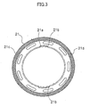
- the brake disc 21 is a circular member having a friction surface 21 d at an outer edge (see Fig. 3) and has a plurality of teeth 21a arranged in an inner periphery.
- the cylinder block 3 has a spline 19 in an outer periphery extending in the axial direction thereof.
- the teeth 21 a engage the spline 19.
- the brake discs 21 rotate together with the cylinder block 3.
- the brake discs 21 slide and move in an axial direction.
- the brake driving device 25 is provided with a brake piston 27, a plurality of brake springs 26, and a pressure chamber 28.
- the brake piston 27 is circular.
- the brake piston 27 moves in the axial direction with respect to the motor casing 11.
- the brake springs 26 press the brake piston 27 on the brake disc 21. As pressure in the pressure chamber 28 increases, the pressure therein drives the brake piston 27 against the brake springs 26.
- the pressure chamber 28 is selectively communicated with the tank or the hydraulic source through a hydraulic circuit (not shown). As the pressure chamber 28 becomes communicated with the tank, the pressure in the pressure chamber 28 decreases. Then the brake spring 26 presses the brake disc 21 on the motor casing 11, to brake the rotation of the cylinder block 3 by reason of friction resistance. On the other hand, when the pressure chamber 28 becomes communicated with the hydraulic source, the pressure in the pressure chamber 28 increases. Then the brake piston 27 moves away from the brake disc 21 against the brake spring 26. At this moment the friction resistance between the brake disc 21 and the brake piston 27 disappears and the braking of the rotation of the cylinder block 3 is released.
- the hydraulic motor 1 is provided with the motor casing 11 and a motor casing 12 where the cylinder block 3 and the brake mechanism 20 are housed.
- the motor casing 12 includes a drain passage 16 that is communicated with the tank (not shown).
- An inside of the motor casings 11, 12 has a first chamber 14 and a second chamber 15 divided by the brake disc 21. Accordingly, when the hydraulic motor 1 is activated, it is possible that a pressure difference occurs between the first chamber 14 and the second chamber 15 therein. When the pressure difference between the first chamber 14 and the second chamber 15 becomes large, the brake disc 21 is pressed on the brake piston 27 or the motor casing 11, thereby to increase the friction resistance.
- the hydraulic motor 1 includes a communicating passage 30 that bypasses the brake disc 21 to communicate the first chamber 14 with the second chamber 15.
- the communicating passage 30 is provided with a through bore 31 and a through bore 32.
- the through bore 31 is formed in the motor casing 11. One end 31 a of the through bore 31 is opened to the first chamber 14. The other end 31 b of the through bore 31 is opened to the surface thereof contacting the motor casing 12.
- the through bore 32 is formed in the motor casing 12. One end 32a of the through bore 32 is opened to the second chamber 15. The other end 32b of the through bore 32 is opened to the surface thereof contacting the motor casing 11 and communicated with the through bore 31.
- the communicating passage 30 communicates the first chamber 14 with the second chamber 15, so that the pressure difference does not occur between the first chamber 14 and the second chamber 15.
- the brake disc 21 includes teeth 21 a disposed in an inner peripheral surface thereof.
- the teeth 21 a engage the spline 19 in the outer peripheral surface of the cylinder block 3.
- Two teeth notches 21b are formed where the teeth 21 a are not formed on partial portions of the inner peripheral surface of the brake disc 21.
- the brake disc 21 includes a plurality of communicating bores 21 c formed at equal intervals in the circumferential direction thereof. The teeth notches 21 b and the respective communicating bores 21c are formed so that the pressure difference between the first chamber 14 and the second chamber 15 is not produced.
- the pressure chamber 28 is communicated with the tank. Then the pressure in the pressure chamber 28 is lowered and the brake spring 26 presses the brake disc 21 on the motor casing 11, causing the friction resistance to occur at the brake disc 21 and thereby braking the rotation of the cylinder block 3.
- the pressure chamber 28 is communicated with the hydraulic source. Then the pressure in the pressure chamber 28 increases and the brake piston 27 moves away from the brake disc 21 against the brake spring 26 and the cylinder block 3 can rotate freely. Next, a hydraulic pressure is introduced to the cylinder 4 and the piston 6 reciprocates by reason of the hydraulic pressure, thereby to rotate and drive the cylinder block 3 through the diagonal plate 7 and the shoe 9.
- the pressure difference does not occur between the first chamber 14 and the second chamber 15.
- the communicating passage 30 is formed in the motor casings 11, 12. Therefore, the operating fluid smoothly flows between the first chamber 14 and the second chamber 15 without any influence of the rotation of the cylinder block 3 and the brake disc 21. As a result, since the pressure difference is not produced between the first chamber 14 and the second chamber 15, when the braking of the brake driving device 25 is released, the friction resistance does not occur in the brake disc 21.
- the disc 21 can be manufactured lighter by reason of forming the communicating bores 21c in the brake disc 21.
- FIG. 4 A second embodiment as shown in Fig. 4 will be explained as follows.
- the same reference numbers are attached to components thereof identical to those of the first embodiment.
- a communicating passage 40 is formed in the output shaft 2 in order to communicate the first chamber 14 with the second chamber 15 and prevents the pressure difference from being produced between the first chamber 14 and the second chamber 15.
- a cross section of the communicating passage 40 is a shape of T- letter.
- the communicating passage 40 is provided with a through bore 41 that is formed extending co-axially with the output shaft 2 and a through bore 42 that is formed extending in the radial direction thereof.
- the through bore 41 of the communicating passage 40 is formed co-axially with the output shaft 2, a position of the through bore 41 does not change regardless of rotation of the output shaft 2. Even when the output shaft 2 rotates, the operating fluid smoothly flows between the first chamber 14 and the second chamber 15 and accordingly, the pressure difference is not produced therebetween. Therefore, when the braking is released, the friction resistance does not occur at the brake disc 21. As a result, when the hydraulic motor 1 is activated, the friction resistance does not occur at the brake disc 21.
- a passage that communicates the second chamber 15 with the tank may be formed independently of a passage that communicates the first chamber 14 with the tank.
- the pressure difference between the first chamber 14 and the second chamber 15 can be restriced.
- the present invention is useful to reduce a friction disc in a brake disc when braking in a hydraulic motor is released.
Landscapes
- Engineering & Computer Science (AREA)
- Chemical & Material Sciences (AREA)
- Combustion & Propulsion (AREA)
- Mechanical Engineering (AREA)
- General Engineering & Computer Science (AREA)
- Hydraulic Motors (AREA)
- Braking Arrangements (AREA)
Abstract
Description
Therefore, a braking force exerts on the output shaft during operating the hydraulic motor and an efficiency of the hydraulic motor threatens to deteriorate.
The
Claims (4)
- A hydraulic motor comprising:an output shaft (2);a cylinder (4) arranged around the output shaft (2) and receiving a plurality of pistons (6) expanding by reason of hydraulic pressure;a diagonal plate (7) that contacts the plurality of the expanding pistons (6), thereby to exert rotational force to the cylinder (4);a brake disc (21) disposed outside the cylinder (4) and rotating therewith;a motor casing (11, 12) receiving the cylinder (4) and the brake disc (21);a brake driving device (25) that presses an outer periphery of the brake disc (21) on an inner peripheral surface of the motor casing (11, 12) to brake the brake disc (21);a first chamber (14) and a second chamber (15) in the motor casing (11, 12) defined by the brake disc (21); anda communicating passage (30 or 40) formed bypassing the brake disc (21) to communicate the first chamber (14) with the second chamber (15).
- A hydraulic motor as defined in claim 1, wherein
the communicating passage (30) is formed in the motor casing (11,12). - A hydraulic motor as defined in claim 1, wherein
the communicating passage (40) is formed in the output shaft (2). - A hydraulic motor as defined in claim 1, wherein the communicating passage (30, 40) is formed in the motor casing (11, 12), as well as the output shaft (2).
Applications Claiming Priority (3)
| Application Number | Priority Date | Filing Date | Title |
|---|---|---|---|
| JP2002219159 | 2002-07-29 | ||
| JP2002219159A JP3911211B2 (en) | 2002-07-29 | 2002-07-29 | Hydraulic motor |
| PCT/JP2003/008408 WO2004011797A1 (en) | 2002-07-29 | 2003-07-02 | Hydraulic motor |
Publications (3)
| Publication Number | Publication Date |
|---|---|
| EP1484500A1 true EP1484500A1 (en) | 2004-12-08 |
| EP1484500A4 EP1484500A4 (en) | 2011-01-12 |
| EP1484500B1 EP1484500B1 (en) | 2012-06-20 |
Family
ID=31184726
Family Applications (1)
| Application Number | Title | Priority Date | Filing Date |
|---|---|---|---|
| EP03738635A Expired - Lifetime EP1484500B1 (en) | 2002-07-29 | 2003-07-02 | Hydraulic motor |
Country Status (5)
| Country | Link |
|---|---|
| US (1) | US7040216B2 (en) |
| EP (1) | EP1484500B1 (en) |
| JP (1) | JP3911211B2 (en) |
| CN (1) | CN100340764C (en) |
| WO (1) | WO2004011797A1 (en) |
Families Citing this family (11)
| Publication number | Priority date | Publication date | Assignee | Title |
|---|---|---|---|---|
| JP2007170543A (en) * | 2005-12-22 | 2007-07-05 | Nabtesco Corp | Brake mechanism of hydraulic motor |
| DE102006058355A1 (en) * | 2006-03-10 | 2007-09-13 | Brueninghaus Hydromatik Gmbh | Combi pump housing for several nominal sizes |
| DE102006025969A1 (en) * | 2006-06-02 | 2007-12-06 | Robert Bosch Gmbh | Hydrostatic piston engine and pressure ring for a braking device of the same |
| US7931362B2 (en) * | 2007-07-13 | 2011-04-26 | Xerox Corporation | System for controlling engagement of a transfix roller with an image receiving member in a printer |
| US20100154626A1 (en) * | 2008-12-22 | 2010-06-24 | Nelson Bryan E | Braking system for a hydraulic motor |
| JP5948081B2 (en) * | 2012-02-22 | 2016-07-06 | Kyb株式会社 | Hydraulic motor |
| JP5891064B2 (en) | 2012-02-22 | 2016-03-22 | Kyb株式会社 | Hydraulic motor |
| FR2987319B1 (en) * | 2012-02-24 | 2014-04-18 | Peugeot Citroen Automobiles Sa | COMPACT HYDRAULIC MODULE FOR HYDRID HYDRAULIC VEHICLE |
| JP2014137009A (en) * | 2013-01-17 | 2014-07-28 | Nachi Fujikoshi Corp | Hydraulic motor |
| JP2016183621A (en) * | 2015-03-26 | 2016-10-20 | Kyb株式会社 | Hydraulic motor, brake device of hydraulic motor, and manufacturing method of brake device |
| US20250035170A1 (en) * | 2023-07-24 | 2025-01-30 | Dana Motion Systems Italia S.R.L. | Actuation system for a motor |
Family Cites Families (10)
| Publication number | Priority date | Publication date | Assignee | Title |
|---|---|---|---|---|
| US3439766A (en) * | 1966-12-29 | 1969-04-22 | Clark Equipment Co | Hydraulic-motor-in-wheel assembly |
| US3808949A (en) * | 1971-06-30 | 1974-05-07 | Deere & Co | Axial piston hydraulic motor |
| DE3028774A1 (en) * | 1980-07-29 | 1982-02-25 | Linde Ag, 6200 Wiesbaden | AXIAL PISTON MOTOR IN DRIVE FLANGE DESIGN WITH A BRAKE |
| KR950019268A (en) * | 1993-12-30 | 1995-07-22 | 김무 | Hydraulic Motor Time Delay Valve |
| JPH0861212A (en) * | 1994-08-26 | 1996-03-08 | Kubota Corp | Hydraulic motor |
| KR100298021B1 (en) * | 1996-10-08 | 2002-04-06 | 세구치 류이치 | Manufacturing method of swash plate hydraulic rotor and casing for two rotor |
| CN2360662Y (en) * | 1998-09-10 | 2000-01-26 | 李志刚 | Internally braking hydraulic motor |
| JP3718080B2 (en) * | 1999-05-07 | 2005-11-16 | 日立建機株式会社 | Hydraulic motor with brake device |
| JP2001020847A (en) * | 1999-07-08 | 2001-01-23 | Teijin Seiki Co Ltd | Fluid motor braking device |
| DE10055262A1 (en) * | 2000-11-08 | 2002-05-23 | Linde Ag | Hydrostatic axial piston machine in inclined disc construction method |
-
2002
- 2002-07-29 JP JP2002219159A patent/JP3911211B2/en not_active Expired - Fee Related
-
2003
- 2003-07-02 CN CNB038089033A patent/CN100340764C/en not_active Expired - Fee Related
- 2003-07-02 WO PCT/JP2003/008408 patent/WO2004011797A1/en not_active Ceased
- 2003-07-02 US US10/508,657 patent/US7040216B2/en not_active Expired - Lifetime
- 2003-07-02 EP EP03738635A patent/EP1484500B1/en not_active Expired - Lifetime
Also Published As
| Publication number | Publication date |
|---|---|
| EP1484500B1 (en) | 2012-06-20 |
| CN100340764C (en) | 2007-10-03 |
| JP3911211B2 (en) | 2007-05-09 |
| US20050252204A1 (en) | 2005-11-17 |
| CN1646804A (en) | 2005-07-27 |
| US7040216B2 (en) | 2006-05-09 |
| JP2004060508A (en) | 2004-02-26 |
| WO2004011797A1 (en) | 2004-02-05 |
| EP1484500A4 (en) | 2011-01-12 |
Similar Documents
| Publication | Publication Date | Title |
|---|---|---|
| EP0421616B1 (en) | Hydraulic device | |
| US7040216B2 (en) | Hydraulic motor | |
| JP5053367B2 (en) | Gerotor motor and brake assembly | |
| EP4208640B1 (en) | Hydrostatic radial piston unit | |
| JP3718080B2 (en) | Hydraulic motor with brake device | |
| KR20150038041A (en) | Combined motor and brake with rotating brake-release piston | |
| EP1974145B1 (en) | Rotary fluid pressure device and improved parking lock assembly therefor | |
| CN114576288A (en) | Radial piston machine with brake | |
| US6253882B1 (en) | Motor with symmetric braking system | |
| EP1882081B1 (en) | Balancing plate-shuttle ball | |
| EP4222370B1 (en) | Brake mechanism for a radial piston unit | |
| JP4577969B2 (en) | Hydraulic motor | |
| JP4164252B2 (en) | Brake device for hydraulic motor | |
| JPH11182410A (en) | Multiple piston pump, valve plate and method of manufacturing the same | |
| JPS6337497Y2 (en) | ||
| JPH0740693Y2 (en) | Hydraulic motor with brake device | |
| JP3668000B2 (en) | Variable displacement swash plate hydraulic motor | |
| JP2024154253A (en) | Hydraulic Rotating Machinery | |
| EP4448953B1 (en) | Bearing arrangement for radial piston units | |
| JPH07310644A (en) | Hydraulic rotary machine with brake device | |
| JPH11141450A (en) | Radial piston motor brake device | |
| JP2000329049A (en) | Hydraulic motor having brake device | |
| JP6010428B2 (en) | Swash plate type hydraulic rotating machine | |
| JP3462978B2 (en) | Lubrication structure of swash plate type double piston pump | |
| JP2559778Y2 (en) | Axial plunger type hydraulic motor |
Legal Events
| Date | Code | Title | Description |
|---|---|---|---|
| PUAI | Public reference made under article 153(3) epc to a published international application that has entered the european phase |
Free format text: ORIGINAL CODE: 0009012 |
|
| 17P | Request for examination filed |
Effective date: 20040907 |
|
| AK | Designated contracting states |
Kind code of ref document: A1 Designated state(s): AT BE BG CH CY CZ DE DK EE ES FI FR GB GR HU IE IT LI LU MC NL PT RO SE SI SK TR |
|
| RBV | Designated contracting states (corrected) |
Designated state(s): DE FR GB IT |
|
| A4 | Supplementary search report drawn up and despatched |
Effective date: 20101209 |
|
| 17Q | First examination report despatched |
Effective date: 20110520 |
|
| GRAP | Despatch of communication of intention to grant a patent |
Free format text: ORIGINAL CODE: EPIDOSNIGR1 |
|
| GRAS | Grant fee paid |
Free format text: ORIGINAL CODE: EPIDOSNIGR3 |
|
| GRAA | (expected) grant |
Free format text: ORIGINAL CODE: 0009210 |
|
| AK | Designated contracting states |
Kind code of ref document: B1 Designated state(s): DE FR GB IT |
|
| REG | Reference to a national code |
Ref country code: GB Ref legal event code: FG4D |
|
| REG | Reference to a national code |
Ref country code: DE Ref legal event code: R081 Ref document number: 60341344 Country of ref document: DE Owner name: KYB CORPORATION, JP Free format text: FORMER OWNER: KAYABA INDUSTRY CO., LTD., TOKYO, JP |
|
| REG | Reference to a national code |
Ref country code: DE Ref legal event code: R096 Ref document number: 60341344 Country of ref document: DE Effective date: 20120809 |
|
| PLBE | No opposition filed within time limit |
Free format text: ORIGINAL CODE: 0009261 |
|
| STAA | Information on the status of an ep patent application or granted ep patent |
Free format text: STATUS: NO OPPOSITION FILED WITHIN TIME LIMIT |
|
| 26N | No opposition filed |
Effective date: 20130321 |
|
| REG | Reference to a national code |
Ref country code: DE Ref legal event code: R097 Ref document number: 60341344 Country of ref document: DE Effective date: 20130321 |
|
| REG | Reference to a national code |
Ref country code: FR Ref legal event code: PLFP Year of fee payment: 13 |
|
| REG | Reference to a national code |
Ref country code: DE Ref legal event code: R082 Ref document number: 60341344 Country of ref document: DE Representative=s name: GRUENECKER PATENT- UND RECHTSANWAELTE PARTG MB, DE Ref country code: DE Ref legal event code: R081 Ref document number: 60341344 Country of ref document: DE Owner name: KYB CORPORATION, JP Free format text: FORMER OWNER: KAYABA INDUSTRY CO., LTD., TOKYO, JP |
|
| REG | Reference to a national code |
Ref country code: FR Ref legal event code: CA Effective date: 20160321 Ref country code: FR Ref legal event code: CD Owner name: KYB CORPORATION, JP Effective date: 20160321 |
|
| REG | Reference to a national code |
Ref country code: FR Ref legal event code: PLFP Year of fee payment: 14 |
|
| REG | Reference to a national code |
Ref country code: FR Ref legal event code: PLFP Year of fee payment: 15 |
|
| REG | Reference to a national code |
Ref country code: FR Ref legal event code: PLFP Year of fee payment: 16 |
|
| PGFP | Annual fee paid to national office [announced via postgrant information from national office to epo] |
Ref country code: IT Payment date: 20180919 Year of fee payment: 8 Ref country code: FR Payment date: 20180725 Year of fee payment: 16 |
|
| PGFP | Annual fee paid to national office [announced via postgrant information from national office to epo] |
Ref country code: GB Payment date: 20180719 Year of fee payment: 16 |
|
| PGFP | Annual fee paid to national office [announced via postgrant information from national office to epo] |
Ref country code: DE Payment date: 20190719 Year of fee payment: 17 |
|
| GBPC | Gb: european patent ceased through non-payment of renewal fee |
Effective date: 20190702 |
|
| PG25 | Lapsed in a contracting state [announced via postgrant information from national office to epo] |
Ref country code: GB Free format text: LAPSE BECAUSE OF NON-PAYMENT OF DUE FEES Effective date: 20190702 |
|
| PG25 | Lapsed in a contracting state [announced via postgrant information from national office to epo] |
Ref country code: FR Free format text: LAPSE BECAUSE OF NON-PAYMENT OF DUE FEES Effective date: 20190731 |
|
| PG25 | Lapsed in a contracting state [announced via postgrant information from national office to epo] |
Ref country code: IT Free format text: LAPSE BECAUSE OF NON-PAYMENT OF DUE FEES Effective date: 20190702 |
|
| REG | Reference to a national code |
Ref country code: DE Ref legal event code: R119 Ref document number: 60341344 Country of ref document: DE |
|
| PG25 | Lapsed in a contracting state [announced via postgrant information from national office to epo] |
Ref country code: DE Free format text: LAPSE BECAUSE OF NON-PAYMENT OF DUE FEES Effective date: 20210202 |