EP1484493A2 - Verfahren zum Betreiben einer Brennkraftmaschine - Google Patents
Verfahren zum Betreiben einer Brennkraftmaschine Download PDFInfo
- Publication number
- EP1484493A2 EP1484493A2 EP04012839A EP04012839A EP1484493A2 EP 1484493 A2 EP1484493 A2 EP 1484493A2 EP 04012839 A EP04012839 A EP 04012839A EP 04012839 A EP04012839 A EP 04012839A EP 1484493 A2 EP1484493 A2 EP 1484493A2
- Authority
- EP
- European Patent Office
- Prior art keywords
- injection
- injections
- qdes
- fuel
- minimum
- Prior art date
- Legal status (The legal status is an assumption and is not a legal conclusion. Google has not performed a legal analysis and makes no representation as to the accuracy of the status listed.)
- Granted
Links
Images


Classifications
-
- F—MECHANICAL ENGINEERING; LIGHTING; HEATING; WEAPONS; BLASTING
- F02—COMBUSTION ENGINES; HOT-GAS OR COMBUSTION-PRODUCT ENGINE PLANTS
- F02D—CONTROLLING COMBUSTION ENGINES
- F02D41/00—Electrical control of supply of combustible mixture or its constituents
- F02D41/30—Controlling fuel injection
- F02D41/38—Controlling fuel injection of the high pressure type
- F02D41/40—Controlling fuel injection of the high pressure type with means for controlling injection timing or duration
- F02D41/402—Multiple injections
- F02D41/403—Multiple injections with pilot injections
-
- F—MECHANICAL ENGINEERING; LIGHTING; HEATING; WEAPONS; BLASTING
- F02—COMBUSTION ENGINES; HOT-GAS OR COMBUSTION-PRODUCT ENGINE PLANTS
- F02D—CONTROLLING COMBUSTION ENGINES
- F02D41/00—Electrical control of supply of combustible mixture or its constituents
- F02D41/30—Controlling fuel injection
- F02D41/38—Controlling fuel injection of the high pressure type
- F02D41/40—Controlling fuel injection of the high pressure type with means for controlling injection timing or duration
- F02D41/402—Multiple injections
-
- F—MECHANICAL ENGINEERING; LIGHTING; HEATING; WEAPONS; BLASTING
- F02—COMBUSTION ENGINES; HOT-GAS OR COMBUSTION-PRODUCT ENGINE PLANTS
- F02D—CONTROLLING COMBUSTION ENGINES
- F02D41/00—Electrical control of supply of combustible mixture or its constituents
- F02D41/02—Circuit arrangements for generating control signals
- F02D41/14—Introducing closed-loop corrections
- F02D41/1438—Introducing closed-loop corrections using means for determining characteristics of the combustion gases; Sensors therefor
- F02D41/1444—Introducing closed-loop corrections using means for determining characteristics of the combustion gases; Sensors therefor characterised by the characteristics of the combustion gases
- F02D41/1446—Introducing closed-loop corrections using means for determining characteristics of the combustion gases; Sensors therefor characterised by the characteristics of the combustion gases the characteristics being exhaust temperatures
-
- F—MECHANICAL ENGINEERING; LIGHTING; HEATING; WEAPONS; BLASTING
- F02—COMBUSTION ENGINES; HOT-GAS OR COMBUSTION-PRODUCT ENGINE PLANTS
- F02D—CONTROLLING COMBUSTION ENGINES
- F02D41/00—Electrical control of supply of combustible mixture or its constituents
- F02D41/30—Controlling fuel injection
- F02D41/38—Controlling fuel injection of the high pressure type
- F02D41/40—Controlling fuel injection of the high pressure type with means for controlling injection timing or duration
- F02D41/402—Multiple injections
- F02D41/405—Multiple injections with post injections
-
- Y—GENERAL TAGGING OF NEW TECHNOLOGICAL DEVELOPMENTS; GENERAL TAGGING OF CROSS-SECTIONAL TECHNOLOGIES SPANNING OVER SEVERAL SECTIONS OF THE IPC; TECHNICAL SUBJECTS COVERED BY FORMER USPC CROSS-REFERENCE ART COLLECTIONS [XRACs] AND DIGESTS
- Y02—TECHNOLOGIES OR APPLICATIONS FOR MITIGATION OR ADAPTATION AGAINST CLIMATE CHANGE
- Y02T—CLIMATE CHANGE MITIGATION TECHNOLOGIES RELATED TO TRANSPORTATION
- Y02T10/00—Road transport of goods or passengers
- Y02T10/10—Internal combustion engine [ICE] based vehicles
- Y02T10/40—Engine management systems
Definitions
- the invention relates to a method for operating a Internal combustion engine with injection system, one being injected Fuel quantity by means of several, during one cycle introduced the internal combustion engine successful injections being one by means of a single injection introduced amount of fuel up to a predetermined minimum amount is changeable and being single or all injections can be turned off.
- Is the injected Fuel quantity below the sum of the predetermined Minimum quantities for the pre-main and post-injection but above the sum of the for the main and post injection given minimum quantities will be the main injection on the preset minimum amount set and the post-injection if possible adjusted to the desired quantity.
- the fuel sharing strategy between the individual injections is therefore chosen so that it allows the control program is to set a control injection.
- the control injection is referred to as the injection which will absorb all the remaining fuel, after the remaining injections on their minimum quantities are set.
- the pilot would be the Be control injection, which absorbs all the fuel, between the for the operating condition of the engine certain desired quantity and the sum of those for the main and Post-injection set minimum quantities remains.
- the invention is intended to achieve the gentlest possible burning process an internal combustion engine can be achieved with injection system.
- a method for operating a Internal combustion engine with injection system in particular one Diesel engine with direct injection, provided, with a injected fuel quantity by means of several, during one Cycle of internal combustion engine injections introduced being one by means of a single injection introduced amount of fuel up to a predetermined Minimum quantity is changeable and being single or all Injections can be switched off, in front of the Disconnecting one injection all injections regardless one possibly for the individual injections Desired amount according to a predetermined Reduzi mecanicsverlauf on the respective predetermined minimum quantity are reduced.
- the distribution of the total to be injected Fuel quantity on the individual injections be coordinated so that as long as possible all injections can be released.
- a will uniform burning process thereby ensuring that the individual injections gradually and according to a predetermined Reduced reduction process to the minimum amount become.
- Essential for the invention is that the individual injections regardless of the previously determined Desired quantities for the individual injections according to a predetermined reduction course if necessary until possible minimum level can be reduced. Before switching off a single injection are thus usually all Injections below the desired quantity intended for them, so the condition with a shut off injection can be achieved gradually. This will be a more uniform Burning process ensured.
- the fuel quantities at for a uniform burning process of particularly important injections be held at high levels for as long as possible. For example a main injection is prioritized and will only after reducing two pilot injections to the reduced minimum amount.
- a linear reduction curve enables the programming and computational effort in a control unit to keep low. This is also important because the given Minimum quantities can be operating point dependent.
- a predefined, linear reduction curve can be defined in easy to adapt to varying minimum quantities. alternative but can also be a quadratic or cubic Reduzi mecanicsverlauf be predetermined, possibly only for individual Injections.
- the problem underlying the invention is also by a control unit for an internal combustion engine with injection system solved, in which means are provided to the internal combustion engine according to the inventive method operate. Furthermore, this is the basis of the invention Problem by an internal combustion engine with injection system and solved a control unit in which the control unit means to the internal combustion engine according to the invention Procedures to operate.
- Modern internal combustion engines with injection system are by means of operated electronic control units, the Control unit injection quantities, injection times and more Setting parameters of the internal combustion engine depending on the operating point look up or calculate in maps.
- the invention can therefore be changed by a hardware in the control unit or by a reprogramming the control unit can be realized.
- the invention can thus also manifest in a computer program that in an electronic control unit of an internal combustion engine, in particular a diesel engine with direct injection, charged can be, and then if it is in the control unit expires, the inventive method for the operation of a Internal combustion engine realized.
- FIG. 1 shows the succession of two pilot injections Pil1 and Pil2 and a main injection HE over time t.
- the pre-injections are numbered so that temporally seen first the second pilot injection Pil2 takes place, then the first pilot injection Pil1 and then the Main injection HE.
- FIG. 1 shows that the second pilot injection Pil2 a shorter injection duration has as the first pilot injection Pil1.
- the Injection duration of the main injection HE is greater as the injection durations of the pilot injections Pil1 and Pil 2 together.
- a total quantity requirement qDes or a total desired quantity for the quantity of fuel to be injected is shown on the accelerator pedal position L.
- the total desired quantity increases consequently with increasing load.
- minimum quantities for the individual injections are entered as horizontally extending lines in the diagram of FIG. Specifically, a minimum amount qMI min for the main injection HE is slightly below 2 mm 3 .
- a minimum amount qPiL1 min for the first pilot injection Pil1 is approximately 1 mm 3
- a minimum amount qPiL2 min for the second pilot injection Pil2 is approximately 1 mm 3 .
- the minimum amount qPil1 min for the first pilot injection is plotted from the minimum amount qMI min for the main injection as a horizontal line in the graph of FIG. 2, and the minimum qPil2 min for the second pilot injection is based on the minimum amount qPil1 min applied as a horizontal line.
- region A no injection is possible in region A, since the desired quantity qDes is less than the minimum amount qMI min for the main injection.
- area B is an injection, namely the main injection, it is possible, as the desired amount qdes is greater than the minimum amount QMI min the main injection but less than the sum of the minimum amount QMI min for the main injection and the minimum amount qPIl1 min for the first pre-injection.
- the area C two injections are possible since the desired quantity qDes is greater than the sum of the minimum amount qMI min for the main injection and the minimum qPil1 min for the first pilot injection, but still smaller than the sum of all three minimum quantities.
- three injections are possible in region D since the predetermined total desired quantity qdes is greater than or equal to the sum of all three minimum quantities.
- FIG 2 shows only an exemplary Course of the total desired quantity qDes as well as the individual minimum quantities, the sake of simplicity than over the accelerator pedal position L are shown constant.
- the minimum quantities an injector or for an injection on the one hand, on the level of fuel pressure, specifically the rail pressure, and on the other hand from the previous injections depend.
- the minimum quantities for the individual injections from the engine operating point and vary.
- the distribution of the total desired amount coordinated to the individual quantities of the individual injections be that as long as possible all injections released and that as even as possible Distribution of the total desired quantity can be made.
- FIG. 3 A reduction curve for the fuel quantities of the individual Injections according to a first embodiment of the invention is shown in FIG.
- FIG. 3 are the injections to be injected with the individual injections Fuel quantities qPil1, qPil2 and qMI over total requested quantity qThis is applied.
- the total desired quantity qDes according to the Sum of single quantities qPil1, qPil2 and qMI plotted.
- the injection quantities qMI, qPil1 and qPil2 are substantially all uniformly reduced to give the total total desired quantity qPil1 + qPi12 + qMI in the sum. It can be seen from FIG. 3 that all three injection quantities qPil1, qPil2 and qMI are reduced in accordance with a linear reduction course, each with a different pitch.
- the sub-quantity qMI for the main injection and the sub-quantity qPil1 for the first pre-injection are reduced according to a linear reduction characteristic.
- different slopes are chosen for the reduction of the subset qMI and the reduction of the subset qPil1.
- the subset qPil1 for the first pilot injection has reached its minimum quantity of 1 mm 3 and the subset qMI for the main injection reaches its minimum quantity of 1.5 mm 3 for this operating point, so that the first pilot injection is switched off.
- the amount of fuel released is added to the only remaining subset qMI for the main injection, so that the mass balance again reaches the total desired amount qDes of 2.5 mm 3 .
- FIG. 4 The representation of Figure 4 shows a comparable to Figure 3 representation.
- a prioritization is made according to Figure 4.
- subset qMI is prioritized over subset qPil1 for the first pilot injection and subset qPil2 for the second pilot injection
- subset qPil1 of the first pilot injection is prioritized over subset qPil2 of the second pilot injection.
- This prioritization is expressed by the fact that starting from a total desired quantity qDes of 6 mm 3, firstly the subset qPil2 for the second pilot injection is reduced to the associated minimum quantity of 1 mm 3 . According to FIG.
- the subset qPil2 assumes its minimum quantity of 1 mm 3 from a total desired quantity of approximately 5.5 mm 3 .
- subset qPil1 and subset qMI remain at a constant value.
- the subset qPil1 is also reduced, down to its minimum quantity of 1.5 mm 3 .
- This minimum quantity of 1.5 mm 3 represents the minimum quantity for qPil1 with a total of three injections. If only the main injection and the first pre-injection are carried out, the minimum quantity for qPil1 drops to 1 mm 3 .
- the subset qMI for the main injection is also reduced.
- the reduction of the subset qMI for the main quantity is carried out linearly up to a value of 2 mm 3 , which is achieved with a total desired quantity qDes of 4.5 mm 3 .
- the second pre-injection with the subset qPil2 is subsequently switched off.
- the amount of fuel released as a result is distributed in each case in half to the subsets qPil1 and qMI, so that the desired quantity qDes is reached again.
- the subset is now first qPil1 reduced according to a linear reduction curve, to the new minimum amount of 1 mm 3 is achieved. This is for a total desired amount qdes of about 3.5 mm 3, the case.
- the subset qMI for the main injection is also reduced according to a linear reduction curve, until the current minimum amount of 1.5 mm 3 for qMI is reached. This is the case for a total desired quantity q of 2.5 mm 3 .
- the first pilot injection is then switched off and the subset qPil1 drops to the value 0.
- the released fuel quantity of the only remaining injection with the subset qMI is added ,
- the minimum quantity specified for an individual injection at an operating point depends on the number of injections.
- the minimum quantity for the qMI subset is 2 mm 3 for three injections, with only two injections for 1.5 mm 3 and with only one injection, namely the main injection, at 1 mm 3 .
- the minimum amount is for the subset qPil1 the first pre-injection with three injections at the value 1.5 mm 3, and only two injections at 1 mm 3.
- FIG. 5 represents an enlarged section of the diagram of FIG. 3, specifically in a range of the total desired quantity qDes between 4 mm 3 and approximately 7 mm 3 .
- the calculation of the reduced subsets shall be explained in an interval from X0 to X1 for the total desired quantity qDes. This is according to Figure 5 of interest for the reduction range amount.
- the amount qMI min Des (1) for the main injection quantity qMI is reached, from which the individual subsets are to be reduced.
- the following boundary conditions apply in the range of quantities between X1 and X0, which is of interest for the reduction, whereby the reduced subset qPil1 should be designated qPillred (1).
- P2red (1) (x1) P2Des (1)
- P2red (1) (x1 / 2) P2min (1).
- FIG. 7 shows an enlarged detail of FIG Diagram of Figure 3 is.
- the quantity range that is interesting for the reduction lies between x1 and x0. At the point x1 is for the subset qMI the value qMIminDes (2) is reached, from which a reduction to be held. For quantities smaller than X0, one injection must be made fall away, since all injections then their minimum quantities achieved.
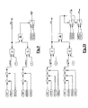
- FIG. 9 shows one for realizing the calculation procedure, as explained with reference to FIG. 5.
- q_leftDes (1) ⁇ 0 is the first pilot injection depending on the given Minimum quantities reduced.
- the size qPillred (1) results when checking that q_leftDes (1)> 0, the Desired quantity qPil1Des (1) for the first pilot injection directly by optionally.
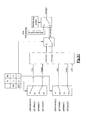
- FIG. 10 shows a structure for realizing the invention 7 illustrated calculation sequence shown.
- FIG. 12 shows a structure suitable for the Implementation of the calculation procedure explained with reference to FIG suitable is.
- a prioritization be desired the subsets qPillred (2) and qPiL2red the first and second pre-injection calculated via the prioritization structure.
- the prioritization list ensures that for P1Des (2), P1min (2), P2Des (2), P2min (2), P3Des (2) and P3min (2) the corresponding sizes are passed on.
Abstract
Description
- Fig. 1
- ein Diagramm mit der zeitlichen Abfolge von Voreinspritzungen und Haupteinspritzung gemäß dem erfindungsgemäßen Verfahren,
- Fig. 2
- ein Diagramm der gesamten, einzuspritzenden Wunschmenge an Kraftstoff über der Fahrpedalstellung,
- Fig. 3
- ein Diagramm mit dem Mengenverlauf für die mit den einzelnen Einspritzungen einzuspritzenden Kraftstoffmengen gemäß einer ersten Ausführungsform der Erfindung,
- Fig. 4
- ein Diagramm mit einem Mengenverlauf für die mit den einzelnen Einspritzungen einzuspritzenden Kraftstoffmengen gemäß einer zweiten Ausführungsform der Erfindung,
- Fig. 5
- eine vergrößerte, ausschnittsweise Darstellung des Diagramms der Figur 3,
- Fig. 6
- eine vergrößerte, ausschnittsweise Darstellung des Diagramms der Figur 4,
- Fig. 7
- einen weiteren, vergrößerten Ausschnitt des Diagramms der Figur 3,
- Fig. 8
- einen weiteren, vergrößerten Ausschnitt des Diagramms der Figur 4,
- Fig. 9
- ein Funktionsschaubild eines Teils einer Steuereinheit zur Realisierung eines Reduzierungsverlaufs für die ersten Voreinspritzungen gemäß dem erfindungsgemäßen Verfahren,
- Fig. 10
- ein Funktionsschaubild zur Realisierung eines Reduzierungsverlaufs für die zweiten Voreinspritzungen,
- Fig. 11
- ein Funktionsschaubild für einen Reduzierungsverlauf bei einer Voreinspritzung und einer Haupteinspritzung mit Priorisierung und
- Fig. 12
- ein Funktionsschaubild zur Reduzierung von zwei Voreinspritzungen und einer Haupteinspritzung mit vorgegebener Priorisierung.
Wunschmenge der Voreinspritzung 1 bei einer aktiven Voreinspritzung
Wunschmenge der Voreinspritzung 1 bei zwei aktiven Voreinspritzungen
Menge der Haupteinspritzung, ab der eine Reduktion beginnen soll für den Fall einer aktiven Voreinspritzung
Menge der Haupteinspritzung, ab der eine Reduktion beginnen soll für den Fall zweier aktiver Voreinspritzungen
Minimalmenge für die Voreinspritzung 1 bei einer aktiven Voreinspritzung
Minimalmenge für die Voreinspritzung 1 bei zwei aktiven Voreinspritzungen
qPil1Des(2)=const.
qPil2Des=const.
qPil1min(2)=const.
qPil2min=const.
Claims (7)
- Verfahren zum Betreiben einer Brennkraftmaschine mit Einspritzanlage, insbesondere eines Dieselmotors mit Direkteinspritzung, wobei eine eingespritzte Kraftstoffmenge mittels mehrerer, während eines Zyklus der Brennkraftmaschine erfolgender Einspritzungen eingebracht wird, wobei eine mittels einer einzelnen Einspritzung eingebrachte Kraftstoffmenge bis zu einer vorgegebenen Mindestmenge veränderbar ist und wobei einzelne oder alle Einspritzungen abgeschaltet werden können,
dadurch gekennzeichnet, dass vor dem Abschalten einer Einspritzung alle Einspritzungen ungeachtet einer für die einzelnen Einspritzungen eventuell vorgegebenen Wunschmenge gemäß einem vorgegebenen Reduzierungsverlauf auf die jeweils vorgegebene Mindestmenge zurückgefahren werden. - Verfahren nach Anspruch 1,
dadurch gekennzeichnet, dass alle Einspritzungen gleichmäßig auf die jeweils vorgegebene Mindestmenge zurückgefahren werden. - Verfahren nach Anspruch 1 oder 2,
dadurch gekennzeichnet, dass eine oder mehrere Einspritzungen priorisiert sind, so dass die priorisierten Einspritzungen erst dann auf ihre jeweils vorgegebenen Mindestmengen zurückgefahren werden, nachdem die übrigen, nicht priorisierten Einspritzungen bereits die jeweilige Mindestmenge aufweisen. - Verfahren nach einem der vorstehenden Ansprüche,
dadurch gekennzeichnet, dass ein linearer Reduzierungsverlauf vorgegeben ist. - Verfahren nach einem der vorstehenden Ansprüche 1 bis 3,
dadurch gekennzeichnet, dass ein quadratischer oder kubischer Reduzierungsverlauf vorgegeben ist. - Steuereinheit für eine Brennkraftmaschine mit Einspritzanlage,
dadurch gekennzeichnet, dass Mittel vorgesehen sind, um die Brennkraftmaschine gemäß dem Verfahren nach einem der Ansprüche 1 bis 5 zu betreiben. - Brennkraftmaschine mit Einspritzanlage und einer Steuereinheit, dadurch gekennzeichnet, dass die Steuereinheit Mittel aufweist, um die Brennkraftmaschine gemäß dem Verfahren nach einem der Ansprüche 1 bis 5 zu betreiben.
Applications Claiming Priority (2)
| Application Number | Priority Date | Filing Date | Title |
|---|---|---|---|
| DE10325988 | 2003-06-07 | ||
| DE10325988A DE10325988A1 (de) | 2003-06-07 | 2003-06-07 | Verfahren zum Betreiben einer Brennkraftmaschine und Brennkraftmaschine |
Publications (3)
| Publication Number | Publication Date |
|---|---|
| EP1484493A2 true EP1484493A2 (de) | 2004-12-08 |
| EP1484493A3 EP1484493A3 (de) | 2005-03-23 |
| EP1484493B1 EP1484493B1 (de) | 2006-05-03 |
Family
ID=33154595
Family Applications (1)
| Application Number | Title | Priority Date | Filing Date |
|---|---|---|---|
| EP04012839A Expired - Fee Related EP1484493B1 (de) | 2003-06-07 | 2004-05-29 | Verfahren zum Betreiben einer Brennkraftmaschine |
Country Status (2)
| Country | Link |
|---|---|
| EP (1) | EP1484493B1 (de) |
| DE (2) | DE10325988A1 (de) |
Citations (3)
| Publication number | Priority date | Publication date | Assignee | Title |
|---|---|---|---|---|
| US5979397A (en) * | 1997-06-30 | 1999-11-09 | Unisia Jecs Corporation | Control apparatus for direct injection spark ignition type internal combustion engine |
| EP1041265A2 (de) * | 1999-04-02 | 2000-10-04 | Isuzu Motors Limited | Common-Rail-Kraftstoffeinspritzsystem |
| US20020195082A1 (en) * | 2000-12-22 | 2002-12-26 | Andreas Pfaeffle | Method and device for injecting fuel in an internal combustion engine |
-
2003
- 2003-06-07 DE DE10325988A patent/DE10325988A1/de not_active Withdrawn
-
2004
- 2004-05-29 DE DE502004000498T patent/DE502004000498D1/de active Active
- 2004-05-29 EP EP04012839A patent/EP1484493B1/de not_active Expired - Fee Related
Patent Citations (3)
| Publication number | Priority date | Publication date | Assignee | Title |
|---|---|---|---|---|
| US5979397A (en) * | 1997-06-30 | 1999-11-09 | Unisia Jecs Corporation | Control apparatus for direct injection spark ignition type internal combustion engine |
| EP1041265A2 (de) * | 1999-04-02 | 2000-10-04 | Isuzu Motors Limited | Common-Rail-Kraftstoffeinspritzsystem |
| US20020195082A1 (en) * | 2000-12-22 | 2002-12-26 | Andreas Pfaeffle | Method and device for injecting fuel in an internal combustion engine |
Also Published As
| Publication number | Publication date |
|---|---|
| DE10325988A1 (de) | 2004-12-23 |
| EP1484493B1 (de) | 2006-05-03 |
| EP1484493A3 (de) | 2005-03-23 |
| DE502004000498D1 (de) | 2006-06-08 |
Similar Documents
| Publication | Publication Date | Title |
|---|---|---|
| DE10296833B4 (de) | Verfahren zur Steuerung des Betriebs einer Kraftstoffeinspritzvorrichtung und Vorrichtung zur Kraftstoffeinspritzung | |
| DE102008054690B4 (de) | Verfahren und Vorrichtung zur Kalibrierung von Teileinspritzungen in einer Brennkraftmaschine, insbesondere eines Kraftfahrzeugs | |
| EP1716331A1 (de) | Verfahren zur zylindergleichstellung bezüglich der kraftstoff-einspritzmengen bei einer brennkraftmaschine | |
| DE102008001111A1 (de) | Verfahren und Vorrichtung zum Betreiben einer Brennkraftmaschine und Brennkraftmaschine | |
| DE102010039841B4 (de) | Verfahren zum Anpassen der Einspritzcharakteristik eines Einspritzventils | |
| EP0995024A1 (de) | Verfahren und vorrichtung zur ansteuerung eines elektromagnetischen verbrauchers | |
| DE3536207C5 (de) | Kraftstoff-Steuersystem für einen Mehrzylinder-Dieselmotor | |
| DE102007043879B4 (de) | Verfahren zum Betreiben eines Einspritzventils | |
| DE102008042933B4 (de) | Verfahren und Vorrichtung zum Dosieren von in einen Brennraum eines Verbrennungsmotors einzuspritzendem Kraftstoff | |
| EP1495222A1 (de) | Verfahren zum berwachen einer brennkraftmaschine | |
| DE102007024823A1 (de) | Verfahren und Vorrichtung zur Bestimmung eines Ansteuerparameters für einen Kraftstoffinjektor einer Brennkraftmaschine | |
| DE102004001119A1 (de) | Verfahren und Vorrichtung zur Steuerung einer Brennkraftmaschine | |
| WO2000045047A1 (de) | Kraftstoffversorgungssystem für eine brennkraftmaschine, insbesondere eines kraftfahrzeugs | |
| EP1347165B1 (de) | Verfahren und Vorrichtung zur Steuerung der Kraftstoffzumessung in eine Brennkraftmaschine | |
| EP1525383A1 (de) | Verfahren zum umrechnen einer kraftstoffmenge in ein drehmoment | |
| DE19931823B4 (de) | Verfahren und Vorrichtung zur Steuerung einer Brennkraftmaschine | |
| EP1488090B1 (de) | Verfahren zum betreiben eines kraftstoffzumesssystems eines kraftfahrzeugs, computerprogramm, steuergerät und kraftstoffzumesssystem | |
| DE19860398B4 (de) | Verfahren und Vorrichtung zur Steuerung der Kraftstoffzumessung in eine Brennkraftmaschine | |
| DE102011075876A1 (de) | Verfahren zum Betreiben einer Einspritzdüse | |
| DE102015220405A1 (de) | Verfahren und Vorrichtung zur Steuerung eines Kraftstoff-Einspritzsystems einer Brennkraftmaschine | |
| DE10243146B3 (de) | Verfahren zur kennfeldbasierten Gewinnung von Werten für einen Steuerparameter einer Anlage | |
| EP1484493B1 (de) | Verfahren zum Betreiben einer Brennkraftmaschine | |
| DE102008001068A1 (de) | Verfahren und Steuergerät zum Betreiben einer Kraftstoffeinspritzanlage | |
| EP1618296B1 (de) | Verfahren zur ermittlung der benötigten aktorenergie für die verschiedenen einspritzarten eines aktors einer brennkraftmaschine | |
| DE102004007799A1 (de) | Verfahren und Vorrichtung zum injektor-individuellen Mengenabgleich in einem Kraftstoffeinspritzsystem einer Brennkraftmaschine |
Legal Events
| Date | Code | Title | Description |
|---|---|---|---|
| PUAI | Public reference made under article 153(3) epc to a published international application that has entered the european phase |
Free format text: ORIGINAL CODE: 0009012 |
|
| AK | Designated contracting states |
Kind code of ref document: A2 Designated state(s): AT BE BG CH CY CZ DE DK EE ES FI FR GB GR HU IE IT LI LU MC NL PL PT RO SE SI SK TR |
|
| AX | Request for extension of the european patent |
Extension state: AL HR LT LV MK |
|
| PUAL | Search report despatched |
Free format text: ORIGINAL CODE: 0009013 |
|
| AK | Designated contracting states |
Kind code of ref document: A3 Designated state(s): AT BE BG CH CY CZ DE DK EE ES FI FR GB GR HU IE IT LI LU MC NL PL PT RO SE SI SK TR |
|
| AX | Request for extension of the european patent |
Extension state: AL HR LT LV MK |
|
| 17P | Request for examination filed |
Effective date: 20050303 |
|
| 17Q | First examination report despatched |
Effective date: 20050504 |
|
| GRAP | Despatch of communication of intention to grant a patent |
Free format text: ORIGINAL CODE: EPIDOSNIGR1 |
|
| AKX | Designation fees paid |
Designated state(s): DE FR GB IT |
|
| GRAS | Grant fee paid |
Free format text: ORIGINAL CODE: EPIDOSNIGR3 |
|
| GRAA | (expected) grant |
Free format text: ORIGINAL CODE: 0009210 |
|
| AK | Designated contracting states |
Kind code of ref document: B1 Designated state(s): DE FR GB IT |
|
| REG | Reference to a national code |
Ref country code: GB Ref legal event code: FG4D Free format text: NOT ENGLISH |
|
| GBT | Gb: translation of ep patent filed (gb section 77(6)(a)/1977) |
Effective date: 20060504 |
|
| REF | Corresponds to: |
Ref document number: 502004000498 Country of ref document: DE Date of ref document: 20060608 Kind code of ref document: P |
|
| ET | Fr: translation filed | ||
| PLBE | No opposition filed within time limit |
Free format text: ORIGINAL CODE: 0009261 |
|
| STAA | Information on the status of an ep patent application or granted ep patent |
Free format text: STATUS: NO OPPOSITION FILED WITHIN TIME LIMIT |
|
| 26N | No opposition filed |
Effective date: 20070206 |
|
| REG | Reference to a national code |
Ref country code: FR Ref legal event code: CD Ref country code: FR Ref legal event code: CA |
|
| PGFP | Annual fee paid to national office [announced via postgrant information from national office to epo] |
Ref country code: IT Payment date: 20110528 Year of fee payment: 8 |
|
| PG25 | Lapsed in a contracting state [announced via postgrant information from national office to epo] |
Ref country code: IT Free format text: LAPSE BECAUSE OF NON-PAYMENT OF DUE FEES Effective date: 20120529 |
|
| REG | Reference to a national code |
Ref country code: FR Ref legal event code: PLFP Year of fee payment: 12 |
|
| PGFP | Annual fee paid to national office [announced via postgrant information from national office to epo] |
Ref country code: GB Payment date: 20150529 Year of fee payment: 12 |
|
| PGFP | Annual fee paid to national office [announced via postgrant information from national office to epo] |
Ref country code: FR Payment date: 20150529 Year of fee payment: 12 |
|
| PGFP | Annual fee paid to national office [announced via postgrant information from national office to epo] |
Ref country code: DE Payment date: 20150730 Year of fee payment: 12 |
|
| REG | Reference to a national code |
Ref country code: DE Ref legal event code: R119 Ref document number: 502004000498 Country of ref document: DE |
|
| GBPC | Gb: european patent ceased through non-payment of renewal fee |
Effective date: 20160529 |
|
| REG | Reference to a national code |
Ref country code: FR Ref legal event code: ST Effective date: 20170131 |
|
| PG25 | Lapsed in a contracting state [announced via postgrant information from national office to epo] |
Ref country code: DE Free format text: LAPSE BECAUSE OF NON-PAYMENT OF DUE FEES Effective date: 20161201 Ref country code: FR Free format text: LAPSE BECAUSE OF NON-PAYMENT OF DUE FEES Effective date: 20160531 |
|
| PG25 | Lapsed in a contracting state [announced via postgrant information from national office to epo] |
Ref country code: GB Free format text: LAPSE BECAUSE OF NON-PAYMENT OF DUE FEES Effective date: 20160529 |