EP1484427A2 - Top coating system for industrial turbine nozzle airfoils and other hot gas path components and related method - Google Patents
Top coating system for industrial turbine nozzle airfoils and other hot gas path components and related method Download PDFInfo
- Publication number
- EP1484427A2 EP1484427A2 EP04253222A EP04253222A EP1484427A2 EP 1484427 A2 EP1484427 A2 EP 1484427A2 EP 04253222 A EP04253222 A EP 04253222A EP 04253222 A EP04253222 A EP 04253222A EP 1484427 A2 EP1484427 A2 EP 1484427A2
- Authority
- EP
- European Patent Office
- Prior art keywords
- coating
- protective top
- top coating
- thermal barrier
- outer protective
- Prior art date
- Legal status (The legal status is an assumption and is not a legal conclusion. Google has not performed a legal analysis and makes no representation as to the accuracy of the status listed.)
- Withdrawn
Links
Images


Classifications
-
- C—CHEMISTRY; METALLURGY
- C23—COATING METALLIC MATERIAL; COATING MATERIAL WITH METALLIC MATERIAL; CHEMICAL SURFACE TREATMENT; DIFFUSION TREATMENT OF METALLIC MATERIAL; COATING BY VACUUM EVAPORATION, BY SPUTTERING, BY ION IMPLANTATION OR BY CHEMICAL VAPOUR DEPOSITION, IN GENERAL; INHIBITING CORROSION OF METALLIC MATERIAL OR INCRUSTATION IN GENERAL
- C23C—COATING METALLIC MATERIAL; COATING MATERIAL WITH METALLIC MATERIAL; SURFACE TREATMENT OF METALLIC MATERIAL BY DIFFUSION INTO THE SURFACE, BY CHEMICAL CONVERSION OR SUBSTITUTION; COATING BY VACUUM EVAPORATION, BY SPUTTERING, BY ION IMPLANTATION OR BY CHEMICAL VAPOUR DEPOSITION, IN GENERAL
- C23C28/00—Coating for obtaining at least two superposed coatings either by methods not provided for in a single one of groups C23C2/00 - C23C26/00 or by combinations of methods provided for in subclasses C23C and C25C or C25D
- C23C28/30—Coatings combining at least one metallic layer and at least one inorganic non-metallic layer
- C23C28/32—Coatings combining at least one metallic layer and at least one inorganic non-metallic layer including at least one pure metallic layer
- C23C28/321—Coatings combining at least one metallic layer and at least one inorganic non-metallic layer including at least one pure metallic layer with at least one metal alloy layer
- C23C28/3215—Coatings combining at least one metallic layer and at least one inorganic non-metallic layer including at least one pure metallic layer with at least one metal alloy layer at least one MCrAlX layer
-
- C—CHEMISTRY; METALLURGY
- C09—DYES; PAINTS; POLISHES; NATURAL RESINS; ADHESIVES; COMPOSITIONS NOT OTHERWISE PROVIDED FOR; APPLICATIONS OF MATERIALS NOT OTHERWISE PROVIDED FOR
- C09D—COATING COMPOSITIONS, e.g. PAINTS, VARNISHES OR LACQUERS; FILLING PASTES; CHEMICAL PAINT OR INK REMOVERS; INKS; CORRECTING FLUIDS; WOODSTAINS; PASTES OR SOLIDS FOR COLOURING OR PRINTING; USE OF MATERIALS THEREFOR
- C09D5/00—Coating compositions, e.g. paints, varnishes or lacquers, characterised by their physical nature or the effects produced; Filling pastes
- C09D5/18—Fireproof paints including high temperature resistant paints
-
- C—CHEMISTRY; METALLURGY
- C04—CEMENTS; CONCRETE; ARTIFICIAL STONE; CERAMICS; REFRACTORIES
- C04B—LIME, MAGNESIA; SLAG; CEMENTS; COMPOSITIONS THEREOF, e.g. MORTARS, CONCRETE OR LIKE BUILDING MATERIALS; ARTIFICIAL STONE; CERAMICS; REFRACTORIES; TREATMENT OF NATURAL STONE
- C04B35/00—Shaped ceramic products characterised by their composition; Ceramics compositions; Processing powders of inorganic compounds preparatory to the manufacturing of ceramic products
- C04B35/01—Shaped ceramic products characterised by their composition; Ceramics compositions; Processing powders of inorganic compounds preparatory to the manufacturing of ceramic products based on oxide ceramics
- C04B35/10—Shaped ceramic products characterised by their composition; Ceramics compositions; Processing powders of inorganic compounds preparatory to the manufacturing of ceramic products based on oxide ceramics based on aluminium oxide
- C04B35/111—Fine ceramics
- C04B35/117—Composites
-
- C—CHEMISTRY; METALLURGY
- C04—CEMENTS; CONCRETE; ARTIFICIAL STONE; CERAMICS; REFRACTORIES
- C04B—LIME, MAGNESIA; SLAG; CEMENTS; COMPOSITIONS THEREOF, e.g. MORTARS, CONCRETE OR LIKE BUILDING MATERIALS; ARTIFICIAL STONE; CERAMICS; REFRACTORIES; TREATMENT OF NATURAL STONE
- C04B35/00—Shaped ceramic products characterised by their composition; Ceramics compositions; Processing powders of inorganic compounds preparatory to the manufacturing of ceramic products
- C04B35/01—Shaped ceramic products characterised by their composition; Ceramics compositions; Processing powders of inorganic compounds preparatory to the manufacturing of ceramic products based on oxide ceramics
- C04B35/16—Shaped ceramic products characterised by their composition; Ceramics compositions; Processing powders of inorganic compounds preparatory to the manufacturing of ceramic products based on oxide ceramics based on silicates other than clay
- C04B35/18—Shaped ceramic products characterised by their composition; Ceramics compositions; Processing powders of inorganic compounds preparatory to the manufacturing of ceramic products based on oxide ceramics based on silicates other than clay rich in aluminium oxide
-
- C—CHEMISTRY; METALLURGY
- C04—CEMENTS; CONCRETE; ARTIFICIAL STONE; CERAMICS; REFRACTORIES
- C04B—LIME, MAGNESIA; SLAG; CEMENTS; COMPOSITIONS THEREOF, e.g. MORTARS, CONCRETE OR LIKE BUILDING MATERIALS; ARTIFICIAL STONE; CERAMICS; REFRACTORIES; TREATMENT OF NATURAL STONE
- C04B35/00—Shaped ceramic products characterised by their composition; Ceramics compositions; Processing powders of inorganic compounds preparatory to the manufacturing of ceramic products
- C04B35/622—Forming processes; Processing powders of inorganic compounds preparatory to the manufacturing of ceramic products
- C04B35/626—Preparing or treating the powders individually or as batches ; preparing or treating macroscopic reinforcing agents for ceramic products, e.g. fibres; mechanical aspects section B
- C04B35/62605—Treating the starting powders individually or as mixtures
- C04B35/62625—Wet mixtures
- C04B35/6263—Wet mixtures characterised by their solids loadings, i.e. the percentage of solids
-
- C—CHEMISTRY; METALLURGY
- C04—CEMENTS; CONCRETE; ARTIFICIAL STONE; CERAMICS; REFRACTORIES
- C04B—LIME, MAGNESIA; SLAG; CEMENTS; COMPOSITIONS THEREOF, e.g. MORTARS, CONCRETE OR LIKE BUILDING MATERIALS; ARTIFICIAL STONE; CERAMICS; REFRACTORIES; TREATMENT OF NATURAL STONE
- C04B35/00—Shaped ceramic products characterised by their composition; Ceramics compositions; Processing powders of inorganic compounds preparatory to the manufacturing of ceramic products
- C04B35/622—Forming processes; Processing powders of inorganic compounds preparatory to the manufacturing of ceramic products
- C04B35/626—Preparing or treating the powders individually or as batches ; preparing or treating macroscopic reinforcing agents for ceramic products, e.g. fibres; mechanical aspects section B
- C04B35/62605—Treating the starting powders individually or as mixtures
- C04B35/62625—Wet mixtures
- C04B35/6264—Mixing media, e.g. organic solvents
-
- C—CHEMISTRY; METALLURGY
- C23—COATING METALLIC MATERIAL; COATING MATERIAL WITH METALLIC MATERIAL; CHEMICAL SURFACE TREATMENT; DIFFUSION TREATMENT OF METALLIC MATERIAL; COATING BY VACUUM EVAPORATION, BY SPUTTERING, BY ION IMPLANTATION OR BY CHEMICAL VAPOUR DEPOSITION, IN GENERAL; INHIBITING CORROSION OF METALLIC MATERIAL OR INCRUSTATION IN GENERAL
- C23C—COATING METALLIC MATERIAL; COATING MATERIAL WITH METALLIC MATERIAL; SURFACE TREATMENT OF METALLIC MATERIAL BY DIFFUSION INTO THE SURFACE, BY CHEMICAL CONVERSION OR SUBSTITUTION; COATING BY VACUUM EVAPORATION, BY SPUTTERING, BY ION IMPLANTATION OR BY CHEMICAL VAPOUR DEPOSITION, IN GENERAL
- C23C28/00—Coating for obtaining at least two superposed coatings either by methods not provided for in a single one of groups C23C2/00 - C23C26/00 or by combinations of methods provided for in subclasses C23C and C25C or C25D
- C23C28/30—Coatings combining at least one metallic layer and at least one inorganic non-metallic layer
- C23C28/34—Coatings combining at least one metallic layer and at least one inorganic non-metallic layer including at least one inorganic non-metallic material layer, e.g. metal carbide, nitride, boride, silicide layer and their mixtures, enamels, phosphates and sulphates
- C23C28/345—Coatings combining at least one metallic layer and at least one inorganic non-metallic layer including at least one inorganic non-metallic material layer, e.g. metal carbide, nitride, boride, silicide layer and their mixtures, enamels, phosphates and sulphates with at least one oxide layer
- C23C28/3455—Coatings combining at least one metallic layer and at least one inorganic non-metallic layer including at least one inorganic non-metallic material layer, e.g. metal carbide, nitride, boride, silicide layer and their mixtures, enamels, phosphates and sulphates with at least one oxide layer with a refractory ceramic layer, e.g. refractory metal oxide, ZrO2, rare earth oxides or a thermal barrier system comprising at least one refractory oxide layer
-
- C—CHEMISTRY; METALLURGY
- C23—COATING METALLIC MATERIAL; COATING MATERIAL WITH METALLIC MATERIAL; CHEMICAL SURFACE TREATMENT; DIFFUSION TREATMENT OF METALLIC MATERIAL; COATING BY VACUUM EVAPORATION, BY SPUTTERING, BY ION IMPLANTATION OR BY CHEMICAL VAPOUR DEPOSITION, IN GENERAL; INHIBITING CORROSION OF METALLIC MATERIAL OR INCRUSTATION IN GENERAL
- C23C—COATING METALLIC MATERIAL; COATING MATERIAL WITH METALLIC MATERIAL; SURFACE TREATMENT OF METALLIC MATERIAL BY DIFFUSION INTO THE SURFACE, BY CHEMICAL CONVERSION OR SUBSTITUTION; COATING BY VACUUM EVAPORATION, BY SPUTTERING, BY ION IMPLANTATION OR BY CHEMICAL VAPOUR DEPOSITION, IN GENERAL
- C23C28/00—Coating for obtaining at least two superposed coatings either by methods not provided for in a single one of groups C23C2/00 - C23C26/00 or by combinations of methods provided for in subclasses C23C and C25C or C25D
- C23C28/30—Coatings combining at least one metallic layer and at least one inorganic non-metallic layer
- C23C28/34—Coatings combining at least one metallic layer and at least one inorganic non-metallic layer including at least one inorganic non-metallic material layer, e.g. metal carbide, nitride, boride, silicide layer and their mixtures, enamels, phosphates and sulphates
- C23C28/347—Coatings combining at least one metallic layer and at least one inorganic non-metallic layer including at least one inorganic non-metallic material layer, e.g. metal carbide, nitride, boride, silicide layer and their mixtures, enamels, phosphates and sulphates with layers adapted for cutting tools or wear applications
-
- C—CHEMISTRY; METALLURGY
- C23—COATING METALLIC MATERIAL; COATING MATERIAL WITH METALLIC MATERIAL; CHEMICAL SURFACE TREATMENT; DIFFUSION TREATMENT OF METALLIC MATERIAL; COATING BY VACUUM EVAPORATION, BY SPUTTERING, BY ION IMPLANTATION OR BY CHEMICAL VAPOUR DEPOSITION, IN GENERAL; INHIBITING CORROSION OF METALLIC MATERIAL OR INCRUSTATION IN GENERAL
- C23C—COATING METALLIC MATERIAL; COATING MATERIAL WITH METALLIC MATERIAL; SURFACE TREATMENT OF METALLIC MATERIAL BY DIFFUSION INTO THE SURFACE, BY CHEMICAL CONVERSION OR SUBSTITUTION; COATING BY VACUUM EVAPORATION, BY SPUTTERING, BY ION IMPLANTATION OR BY CHEMICAL VAPOUR DEPOSITION, IN GENERAL
- C23C30/00—Coating with metallic material characterised only by the composition of the metallic material, i.e. not characterised by the coating process
-
- F—MECHANICAL ENGINEERING; LIGHTING; HEATING; WEAPONS; BLASTING
- F01—MACHINES OR ENGINES IN GENERAL; ENGINE PLANTS IN GENERAL; STEAM ENGINES
- F01D—NON-POSITIVE DISPLACEMENT MACHINES OR ENGINES, e.g. STEAM TURBINES
- F01D5/00—Blades; Blade-carrying members; Heating, heat-insulating, cooling or antivibration means on the blades or the members
- F01D5/12—Blades
- F01D5/28—Selecting particular materials; Particular measures relating thereto; Measures against erosion or corrosion
- F01D5/288—Protective coatings for blades
-
- C—CHEMISTRY; METALLURGY
- C04—CEMENTS; CONCRETE; ARTIFICIAL STONE; CERAMICS; REFRACTORIES
- C04B—LIME, MAGNESIA; SLAG; CEMENTS; COMPOSITIONS THEREOF, e.g. MORTARS, CONCRETE OR LIKE BUILDING MATERIALS; ARTIFICIAL STONE; CERAMICS; REFRACTORIES; TREATMENT OF NATURAL STONE
- C04B2235/00—Aspects relating to ceramic starting mixtures or sintered ceramic products
- C04B2235/02—Composition of constituents of the starting material or of secondary phases of the final product
- C04B2235/30—Constituents and secondary phases not being of a fibrous nature
- C04B2235/32—Metal oxides, mixed metal oxides, or oxide-forming salts thereof, e.g. carbonates, nitrates, (oxy)hydroxides, chlorides
- C04B2235/3217—Aluminum oxide or oxide forming salts thereof, e.g. bauxite, alpha-alumina
-
- C—CHEMISTRY; METALLURGY
- C04—CEMENTS; CONCRETE; ARTIFICIAL STONE; CERAMICS; REFRACTORIES
- C04B—LIME, MAGNESIA; SLAG; CEMENTS; COMPOSITIONS THEREOF, e.g. MORTARS, CONCRETE OR LIKE BUILDING MATERIALS; ARTIFICIAL STONE; CERAMICS; REFRACTORIES; TREATMENT OF NATURAL STONE
- C04B2235/00—Aspects relating to ceramic starting mixtures or sintered ceramic products
- C04B2235/02—Composition of constituents of the starting material or of secondary phases of the final product
- C04B2235/30—Constituents and secondary phases not being of a fibrous nature
- C04B2235/32—Metal oxides, mixed metal oxides, or oxide-forming salts thereof, e.g. carbonates, nitrates, (oxy)hydroxides, chlorides
- C04B2235/3231—Refractory metal oxides, their mixed metal oxides, or oxide-forming salts thereof
- C04B2235/3232—Titanium oxides or titanates, e.g. rutile or anatase
- C04B2235/3234—Titanates, not containing zirconia
-
- C—CHEMISTRY; METALLURGY
- C04—CEMENTS; CONCRETE; ARTIFICIAL STONE; CERAMICS; REFRACTORIES
- C04B—LIME, MAGNESIA; SLAG; CEMENTS; COMPOSITIONS THEREOF, e.g. MORTARS, CONCRETE OR LIKE BUILDING MATERIALS; ARTIFICIAL STONE; CERAMICS; REFRACTORIES; TREATMENT OF NATURAL STONE
- C04B2235/00—Aspects relating to ceramic starting mixtures or sintered ceramic products
- C04B2235/02—Composition of constituents of the starting material or of secondary phases of the final product
- C04B2235/30—Constituents and secondary phases not being of a fibrous nature
- C04B2235/32—Metal oxides, mixed metal oxides, or oxide-forming salts thereof, e.g. carbonates, nitrates, (oxy)hydroxides, chlorides
- C04B2235/3284—Zinc oxides, zincates, cadmium oxides, cadmiates, mercury oxides, mercurates or oxide forming salts thereof
-
- C—CHEMISTRY; METALLURGY
- C04—CEMENTS; CONCRETE; ARTIFICIAL STONE; CERAMICS; REFRACTORIES
- C04B—LIME, MAGNESIA; SLAG; CEMENTS; COMPOSITIONS THEREOF, e.g. MORTARS, CONCRETE OR LIKE BUILDING MATERIALS; ARTIFICIAL STONE; CERAMICS; REFRACTORIES; TREATMENT OF NATURAL STONE
- C04B2235/00—Aspects relating to ceramic starting mixtures or sintered ceramic products
- C04B2235/02—Composition of constituents of the starting material or of secondary phases of the final product
- C04B2235/30—Constituents and secondary phases not being of a fibrous nature
- C04B2235/34—Non-metal oxides, non-metal mixed oxides, or salts thereof that form the non-metal oxides upon heating, e.g. carbonates, nitrates, (oxy)hydroxides, chlorides
- C04B2235/3418—Silicon oxide, silicic acids, or oxide forming salts thereof, e.g. silica sol, fused silica, silica fume, cristobalite, quartz or flint
-
- C—CHEMISTRY; METALLURGY
- C04—CEMENTS; CONCRETE; ARTIFICIAL STONE; CERAMICS; REFRACTORIES
- C04B—LIME, MAGNESIA; SLAG; CEMENTS; COMPOSITIONS THEREOF, e.g. MORTARS, CONCRETE OR LIKE BUILDING MATERIALS; ARTIFICIAL STONE; CERAMICS; REFRACTORIES; TREATMENT OF NATURAL STONE
- C04B2235/00—Aspects relating to ceramic starting mixtures or sintered ceramic products
- C04B2235/02—Composition of constituents of the starting material or of secondary phases of the final product
- C04B2235/50—Constituents or additives of the starting mixture chosen for their shape or used because of their shape or their physical appearance
- C04B2235/54—Particle size related information
- C04B2235/5409—Particle size related information expressed by specific surface values
-
- C—CHEMISTRY; METALLURGY
- C04—CEMENTS; CONCRETE; ARTIFICIAL STONE; CERAMICS; REFRACTORIES
- C04B—LIME, MAGNESIA; SLAG; CEMENTS; COMPOSITIONS THEREOF, e.g. MORTARS, CONCRETE OR LIKE BUILDING MATERIALS; ARTIFICIAL STONE; CERAMICS; REFRACTORIES; TREATMENT OF NATURAL STONE
- C04B2235/00—Aspects relating to ceramic starting mixtures or sintered ceramic products
- C04B2235/02—Composition of constituents of the starting material or of secondary phases of the final product
- C04B2235/50—Constituents or additives of the starting mixture chosen for their shape or used because of their shape or their physical appearance
- C04B2235/54—Particle size related information
- C04B2235/5418—Particle size related information expressed by the size of the particles or aggregates thereof
- C04B2235/5436—Particle size related information expressed by the size of the particles or aggregates thereof micrometer sized, i.e. from 1 to 100 micron
-
- C—CHEMISTRY; METALLURGY
- C04—CEMENTS; CONCRETE; ARTIFICIAL STONE; CERAMICS; REFRACTORIES
- C04B—LIME, MAGNESIA; SLAG; CEMENTS; COMPOSITIONS THEREOF, e.g. MORTARS, CONCRETE OR LIKE BUILDING MATERIALS; ARTIFICIAL STONE; CERAMICS; REFRACTORIES; TREATMENT OF NATURAL STONE
- C04B2235/00—Aspects relating to ceramic starting mixtures or sintered ceramic products
- C04B2235/02—Composition of constituents of the starting material or of secondary phases of the final product
- C04B2235/50—Constituents or additives of the starting mixture chosen for their shape or used because of their shape or their physical appearance
- C04B2235/54—Particle size related information
- C04B2235/5418—Particle size related information expressed by the size of the particles or aggregates thereof
- C04B2235/5445—Particle size related information expressed by the size of the particles or aggregates thereof submicron sized, i.e. from 0,1 to 1 micron
-
- C—CHEMISTRY; METALLURGY
- C04—CEMENTS; CONCRETE; ARTIFICIAL STONE; CERAMICS; REFRACTORIES
- C04B—LIME, MAGNESIA; SLAG; CEMENTS; COMPOSITIONS THEREOF, e.g. MORTARS, CONCRETE OR LIKE BUILDING MATERIALS; ARTIFICIAL STONE; CERAMICS; REFRACTORIES; TREATMENT OF NATURAL STONE
- C04B2235/00—Aspects relating to ceramic starting mixtures or sintered ceramic products
- C04B2235/02—Composition of constituents of the starting material or of secondary phases of the final product
- C04B2235/50—Constituents or additives of the starting mixture chosen for their shape or used because of their shape or their physical appearance
- C04B2235/54—Particle size related information
- C04B2235/5463—Particle size distributions
- C04B2235/5472—Bimodal, multi-modal or multi-fraction
-
- F—MECHANICAL ENGINEERING; LIGHTING; HEATING; WEAPONS; BLASTING
- F05—INDEXING SCHEMES RELATING TO ENGINES OR PUMPS IN VARIOUS SUBCLASSES OF CLASSES F01-F04
- F05D—INDEXING SCHEME FOR ASPECTS RELATING TO NON-POSITIVE-DISPLACEMENT MACHINES OR ENGINES, GAS-TURBINES OR JET-PROPULSION PLANTS
- F05D2230/00—Manufacture
- F05D2230/90—Coating; Surface treatment
-
- F—MECHANICAL ENGINEERING; LIGHTING; HEATING; WEAPONS; BLASTING
- F05—INDEXING SCHEMES RELATING TO ENGINES OR PUMPS IN VARIOUS SUBCLASSES OF CLASSES F01-F04
- F05D—INDEXING SCHEME FOR ASPECTS RELATING TO NON-POSITIVE-DISPLACEMENT MACHINES OR ENGINES, GAS-TURBINES OR JET-PROPULSION PLANTS
- F05D2300/00—Materials; Properties thereof
- F05D2300/60—Properties or characteristics given to material by treatment or manufacturing
- F05D2300/611—Coating
-
- Y—GENERAL TAGGING OF NEW TECHNOLOGICAL DEVELOPMENTS; GENERAL TAGGING OF CROSS-SECTIONAL TECHNOLOGIES SPANNING OVER SEVERAL SECTIONS OF THE IPC; TECHNICAL SUBJECTS COVERED BY FORMER USPC CROSS-REFERENCE ART COLLECTIONS [XRACs] AND DIGESTS
- Y02—TECHNOLOGIES OR APPLICATIONS FOR MITIGATION OR ADAPTATION AGAINST CLIMATE CHANGE
- Y02T—CLIMATE CHANGE MITIGATION TECHNOLOGIES RELATED TO TRANSPORTATION
- Y02T50/00—Aeronautics or air transport
- Y02T50/60—Efficient propulsion technologies, e.g. for aircraft
Definitions
- This invention relates to coatings for components exposed to high temperatures, such as those in the hostile thermal environment of a gas turbine engine. More particularly, this invention is directed to a protective top coating applied over a thermal barrier coating (TBC) on components located in the hot gas path of a gas turbine engine.
- TBC thermal barrier coating
- Gas turbine engine components e.g., stationary blades or nozzles, rotating blades, and combustion hardware experience performance degradation during operation due to such things as surface erosion and fouling.
- the lives of the components are also impacted by, among other things, the extremely high temperatures to which they are exposed.
- TBC thermal barrier coating
- Ceramic materials and particularly yttria-stabilized zirconia (YSZ) are widely used as TBC materials because of their high temperature capability, low thermal conductivity, and relative ease of deposition by plasma spraying, flame spraying and physical vapor deposition (PVD) techniques.
- Air plasma spraying (APS) is often preferred over other deposition processes due to relatively low equipment costs and ease of application and masking.
- TBC surface finishes are extremely rough and prone to erosion.
- the TBC surface roughness is greater than the parent metal surface finish, thus increasing external heat transfer and overall nozzle heat load as well as negatively impacting aerodynamic performance.
- TBC surface degradation is often the result of fouling due to burning fuels containing alkali metals that combine with sulfur during the combustion process and deposit low melting salts on the surface of the parts. Contaminants can also come from the air ingested or water injected for NO x control or power augmentation. Further degradation occurs due to erosion of the TBC material itself.
- the service life of a TBC system is typically limited by a spallation event brought on by thermal fatigue.
- spallation can be promoted as a result of the TBC being contaminated with compounds found within a gas turbine engine during its operation.
- the protective coating is comprised of alumina particles in a matrix material, with a suitable carrier liquid such as methanol, ethanol, etc.
- the protective coating is designed to reduce if not prevent the infiltration of CMAS into the underlying TBC. See U.S. Patent No. 6,465,090.
- This invention takes the prior teachings one step further by determining the thickness of the protective coating as described in the '090 patent as a function of TBC temperature in use.
- the end result is a smooth protective barrier coating applied over the traditional TBC that protects the TBC from erosion, provides a smooth surface on which contaminants can not adhere, reduces heat transfer, reduces susceptibility to surface fouling and improves aerodynamic performance.
- the protective top coating comprises alumina particles in a silica-containing matrix.
- the coating may be substantially homogeneous or be formed of multiple layers having different compositions.
- the invention relates to a turbine component adapted for use in a hot gas path of a gas turbine having a thermal barrier coating of predetermined thickness on at least one surface portion thereof, the turbine component further comprising a protective top coating applied over the thermal barrier coating, the predetermined thickness determined as a function of in-use temperature of the thermal barrier coating.
- the invention in another aspect, relates to a component having a thermal barrier coating on a surface thereof, the component comprising an outer protective top coating overlying the thermal barrier coating, the outer protective top coating comprising alumina particles in a silica-containing matrix, the alumina particles constituting about 5 to about 85 weight percent of the outer protective top coating, and the silica-containing matrix consisting essentially of at least one of silica, silicate, and mullite, and constituting about 1 to about 45 weight percent of the outer protective top coating; and wherein the thermal barrier coating has a thickness determined as a function of in-use temperature of the thermal barrier coating.
- the invention relates to a gas turbine engine component having a thermal barrier coating of partially-stabilized zirconia on a surface thereof, the component comprising an outer protective top coating overlying the thermal barrier coating, the outer protective top coating comprising alumina particles in a binder matrix, the binder matrix consisting essentially of at least one of silica, silicate and mullite, the alumina particles constituting about 5 to about 85 weight percent of the outer protective top coating, the binder matrix constituting about 1 to about 45 weight percent of the outer protective top coating, the outer protective top coating having a surface roughness of not greater than 3.8 micrometers Ra, and wherein the thermal barrier coating has a thickness determined as a function of in-use temperature of the thermal barrier coating.
- the invention in still another aspect, relates to a method of preventing spallation of a protective top coating applied over a thermal barrier coating on a gas turbine engine component comprising determining when spallation of the protective top coating occurs as a function of minimum effective thickness and in-use temperature of the thermal barrier coating; and choosing a thickness for the thermal barrier coating that is at least equal to the minimum effective thickness.
- a typical gas turbine 2 includes a multi-stage compressor, multiple (e.g., six, ten, fourteen, etc.) combustors (oriented in a circular array about the rotor), with three or four turbine stages. As shown in Figure 1, each combustor 10 of the turbine 2 includes a combustion chamber 14 surrounded by a slot-cooled liner assembly 16 which, in turn, is enclosed partially within a flow sleeve 18.
- the liner assembly 16 and flow sleeve 18 are enclosed within a cylindrical combustor casing 20.
- a fuel nozzle assembly 22 is mounted at the rear of the casing 20, and supplies fuel to the combustion chamber.
- Compressor discharge air is supplied to the combustor for reverse flow between the flow sleeve and liner and into the combustion zone or chamber.
- Combustion gases are supplied to the turbine stages via transition pieces connected to each combustor. One such transition piece is indicated at 24.
- the turbine rotor, generally designated 26 is comprised of stacked elements, for example, the rotor wheels 28, 30, 32 and 34 which form portions of an exemplary four-stage turbine rotor, with spacers 36, 38 and 40 alternating between the wheels.
- the wheels 28, 30, 32 and 34 each mount a plurality of circumferentially spaced turbine buckets, as indicated, respectively, at 42, 44, 46 and 48.
- Stationary nozzles 50, 52, 54 and 56 combine with adjacent rows of buckets to form the four turbine stages.
- Figures 1 and 2 thus illustrate the various components in the hot gas path of the turbine 2 that are candidates for the TBC and top coatings as described herein.
- nozzle 50 for example, nozzle 50, as shown in Figure 2
- the invention is generally applicable to any component that operates within the hot gas path section of the turbine.
- Such components include rotating buckets or blades, combustion hardware including liners, transition pieces, combustion chamber caps, splash plates, etc.
- the nozzle 50 generally includes an airfoil portion against which hot combustion gases are directed during operation of the gas turbine engine, and whose surface is therefore subjected to severe attack by oxidation, hot corrosion and erosion.
- the coating system includes a bond coat 60 overlying a substrate 56, which represents the base material of the nozzle 50.
- Suitable materials for the nozzle 50 include equiaxed, directionally-solidified and single-crystal nickel, iron and cobalt-base superalloys, as well as nonmetallic structural materials including ceramic matrix composite (CMC) materials.
- the bond coat 60 may be an overlay coating such as MCrAIX (where M is iron, cobalt and/or nickel, and X is yttrium or another rare earth element), or a diffusion aluminide coating such as a platinum aluminide.
- the bond coat 60 is shown as adhering a thermal barrier coating (TBC) 62 to the substrate 56.
- TBC thermal barrier coating
- a preferred material for the TBC 62 is an yttria-stabilized zirconia (YSZ), a preferred composition being about 3 to about 8 weight percent yttria, though other ceramic materials could be used, such as alumina, nonstabilized zirconia, or zirconia partially or fully stabilized by magnesia, ceria, scandia or other oxides.
- the TBC 62 is depicted as having been deposited by air plasma spraying (APS), by which "splats" of molten material are deposited on the bond coat 60. As indicated, the TBC 62 has a degree of inhomogeneity and porosity that typically occurs in coatings produced by plasma spraying. In addition, the surface of the TBC 62 is relatively coarse, with a surface roughness of 200 to 500 microinches Ra (about 5 to 13 micrometers Ra) being typical for YSZ deposited by APS (APSTBC). While depositing the TBC 62 by APS is particularly suitable, other plasma spraying techniques could also be used, such as low pressure plasma spraying (LPPS; also known as vacuum plasma spraying (VPS)). The TBC 62 is deposited to a thickness that is sufficient to provide the required thermal protection for the underlying substrate 56 and airfoil portion thereof on the order of about 75 to about 500 micrometers.
- LPPS low pressure plasma spraying
- VPS vacuum plasma spraying
- TBC systems use YSZ deposited by APS as the outermost layer
- drawbacks include the roughness of the TBC surface, erosion resistance, and transmissivity to infrared (IR) radiation.
- IR infrared
- surface roughness increases turbulent transfer from the hot combustion gases to the component and reduces aerodynamic performance.
- surface roughness can be reduced by polishing, such as tumbling or hand polishing, the final surface finish and thickness of the TBC cannot be closely controlled and the additional processing costs are undesirable.
- crystalline YSZ is very resistant to erosion
- the erosion resistance of a YSZ APSTBC is significantly reduced as a result of its porosity and "microcrack" structure, the result of which is that fine particle bombardment dislodges small pieces of the TBC.
- IR transmissivity analysis has shown that YSZ is about 20% to 40% transparent to thermal radiation (wavelengths of about 780 mm to about 1 mm) when deposited by APS to thicknesses of about 250 to 500 micrometers.
- the thermal protection provided by YSZ APSTBC is compromised in environments that have high thermal radiation loads, such as within a gas turbine engine.
- the TBC 62 in Figure 3 is overcoated by a protective top coating 64.
- the protective coating 64 determines the surface roughness of the nozzle.
- the protective top coating 64 of this invention also serves as a barrier to thermal radiation and erosion.
- the protective top coating 64 achieves these features of the invention as a result of its thickness, composition and method of deposition.
- the protective top coating 64 is generally an alumina-base-silica-bound ceramic material. More particularly, the protective top coating 64 contains particles of alumina (Al 2 O 3 ) that are dispersed within a binder matrix composed of silica (SiO 2 ), silicates and/or mullite (3Al 2 O 3 2SiO 2 ), the relative amounts of which will vary depending on the firing temperature and subsequent service temperatures seen by the coating 64, with greater amounts of mullite forming at higher temperatures.
- the alumina particles constitute at least 5 up to about 85 weight percent of the outer protective top coating 64, while the silica-containing binder matrix constitutes about 1 to about 45 weight percent of the protective top coating 64.
- the relative amounts of alumina and silica-based matrix material in the protective top coating 64 can be tailored depending on the desired properties. Higher silica contents depress the CTE of the coating 64 and promote glass formation, while higher alumina contents have the generally preferred opposite effect, since a higher CTE reduces the CTE mismatch of the protective top coating 64 with a metallic substrate 58.
- Additional ceramic constituents for the protective coating 64 include zirconia (particularly YSZ), zinc titanate, and glass materials if present in appropriately limited amounts. For example, additions of zirconia are beneficial to increase the CTE of the coating 64, and additions of zinc titanate promote the reflectivity of the coating 64 to thermal radiation.
- the alumina particles may be present within the protective top coating 64 in two discrete particle size ranges. If such a bimodal size distribution is used, a suitable particle size range for the coarser constituent is about 3.0 to about 6.0 micrometers in diameter, the particles of which constitute about 15 to about 55 weight percent of the protective coating. A preferred alumina powder for the coarser constituent has a particle size range of about 3.0 to about 5.5 micrometers in diameter. A suitable particle size range for the finer alumina particles of a bimodal powder is about 0.05 to about 0.8 micrometers in diameter, the particles of which constitute about 8 to about 45 weight percent of the coating 64. A preferred alumina powder for the finer constituent has a particle size range of about 0.10 to about 0.6 micrometers in diameter.
- the finer particles are able to fill the spaces between the larger particles at the surface of the protective coating 64 to achieve a surface roughness of not more than about 2.5 micrometers Ra, typically in the range of about 1.5 to 2.5 micrometers Ra (about 50 to 400/500 Ra), which is significantly smoother than that possible for the TBC 62 when deposited by APS (typically about 10 to 15 micrometers Ra(about 500 to 600 microinches Ra)).
- a surface roughness of the alumina particles is that at very high temperatures, silica within the matrix of the protective top coating 64 preferentially reacts with the finer alumina particles to form a mullite phase.
- Alumina powders for both the coarser and finer constituents are commercially available.
- a suitable alumina powder for the coarser constituent is available under the designation A14 from ALCOA, which has a low soda content (NAO 2 ⁇ 0.10 percent) and a surface area of about 0.5 m 2 /g.
- a suitable alumina powder for the finer constituent is available under the designation Baikalox SM8 from Baikowski International Corporation, and has a surface area of about 10 m 2 /g and an agglomerate size distribution (on a cumulative weight basis) of 65% below 0.3 micrometer, 78% below 0.4 micrometer, 95% below 0.6 micrometer, and 100% below 1.0 micrometer.
- the protective top coating 64 must be capable of being deposited in such a manner as to have a smoother surface finish than the underlying TBC 62.
- the protective top coating 64 is deposited by spraying a slurry that contains the alumina particles, a precursor of the silica-containing matrix, and a carrier liquid or solvent.
- a suitable precursor for the slurry is a silicone such as polymethyl siloxane, a particular example of which is a resin manufactured by GE Silicones under the name SR350, and classified as a methylsesquisiloxane mixture of the polysiloxane family.
- a suitable carrier liquid is an anhydrous alcohol such as methanol or ethanol, though acetone, isopropyl alcohol or trichloroethylene could be used.
- a suitable slurry contains about 40 to about 65 weight percent of the alumina powder (preferably having the two particle size ranges discussed above), about 1 to about 45 weight percent of the silica precursor, and about 5 to about 90 weight percent of the carrier liquid.
- An additional and optional constituent is zinc titanate in amounts of up to about 50 weight percent of the slurry to promote the reflectivity of the coating 64 to thermal radiation.
- the composition After being sprayed on the TBC 62 using any suitable sprayer known in the art, the composition can be dried at room temperature and then fired to yield a substantially homogeneous protective coating 64 with a surface roughness in the range of about 40 to 150 microinches Ra (about 1 to about 3.8 micrometers Ra).
- the composition of the sprayed protective coating 64 is preferably about 30 to about 55 weight percent of the coarser alumina, about 20 to about 40 weight percent of the finer alumina, up to about 30 weight percent zinc titanate (if present0, and about 25 to about 45 weight percent of the silica-containing matrix.
- the outer layer of the protective top coating 64 may contain, in addition to the alumina powder and silica precursor, a glass frit material and zinc titanate (Zn 2 TiO 4 ), the latter of which promotes the reflectivity of the coating.
- the thickness, structure and properties of the protective coating 64 can be tailored by the firing temperature and duration used. Suitable thicknesses for the protective top coating may be in the range of about 25 to about 150 micrometers.
- the thickness of the TBC 62 is preferably determined as a function of the operating or in-use temperature of the TBC as described below.
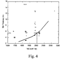
- Figure 4 illustrates in graph form the relationship between thickness of the TBC 62 and the operating temperature of the TBC designed to operate in use at temperature ranges of between about 1750°F and 2200°F. If, for example, the operating temperature of the TBC 62 is 2000°F, the minimum acceptable thickness for the TBC 62 would be about 5.5 mils.
- the thickness of the TBC 62 should be at least and preferably greater than the minimum effective thickness represented by the curve. It will be appreciated that suitable graphs may be developed for the various turbine components, depending on expected TBC temperatures.
Landscapes
- Chemical & Material Sciences (AREA)
- Engineering & Computer Science (AREA)
- Materials Engineering (AREA)
- Organic Chemistry (AREA)
- Inorganic Chemistry (AREA)
- Ceramic Engineering (AREA)
- Mechanical Engineering (AREA)
- Chemical Kinetics & Catalysis (AREA)
- Metallurgy (AREA)
- Manufacturing & Machinery (AREA)
- Structural Engineering (AREA)
- General Engineering & Computer Science (AREA)
- Composite Materials (AREA)
- Life Sciences & Earth Sciences (AREA)
- Wood Science & Technology (AREA)
- Turbine Rotor Nozzle Sealing (AREA)
- Other Surface Treatments For Metallic Materials (AREA)
- Paints Or Removers (AREA)
Abstract
Description
- This invention relates to coatings for components exposed to high temperatures, such as those in the hostile thermal environment of a gas turbine engine. More particularly, this invention is directed to a protective top coating applied over a thermal barrier coating (TBC) on components located in the hot gas path of a gas turbine engine.
- Gas turbine engine components, e.g., stationary blades or nozzles, rotating blades, and combustion hardware experience performance degradation during operation due to such things as surface erosion and fouling. The lives of the components are also impacted by, among other things, the extremely high temperatures to which they are exposed.
- Combustion hardware and other hot gas path components of gas turbine engines are often protected by a thermal barrier coating or TBC, which reduces the temperature of the underlying component substrate and thereby prolongs the service life of the component. Ceramic materials and particularly yttria-stabilized zirconia (YSZ) are widely used as TBC materials because of their high temperature capability, low thermal conductivity, and relative ease of deposition by plasma spraying, flame spraying and physical vapor deposition (PVD) techniques. Air plasma spraying (APS) is often preferred over other deposition processes due to relatively low equipment costs and ease of application and masking.
- Unfortunately, TBC surface finishes are extremely rough and prone to erosion. In fact, the TBC surface roughness is greater than the parent metal surface finish, thus increasing external heat transfer and overall nozzle heat load as well as negatively impacting aerodynamic performance. TBC surface degradation is often the result of fouling due to burning fuels containing alkali metals that combine with sulfur during the combustion process and deposit low melting salts on the surface of the parts. Contaminants can also come from the air ingested or water injected for NOx control or power augmentation. Further degradation occurs due to erosion of the TBC material itself.
- More specifically, it is recognized that the service life of a TBC system is typically limited by a spallation event brought on by thermal fatigue. In addition to the CTE mismatch between a ceramic TBC and a metallic substrate, spallation can be promoted as a result of the TBC being contaminated with compounds found within a gas turbine engine during its operation.
- In aircraft gas turbine engine components, diffuse reflective barrier coatings have been applied over TBC's with an outer low emissivity topcoat applied over the reflective barrier coating. The additional top coat is designed to reduce heat flow into the component. See U.S. Patent No. 6,210,791.
- It is also known to apply a protective coating over TBC's to protect the TBC, where the protective coating is comprised of alumina particles in a matrix material, with a suitable carrier liquid such as methanol, ethanol, etc. The protective coating is designed to reduce if not prevent the infiltration of CMAS into the underlying TBC. See U.S. Patent No. 6,465,090.
- This invention takes the prior teachings one step further by determining the thickness of the protective coating as described in the '090 patent as a function of TBC temperature in use. The end result is a smooth protective barrier coating applied over the traditional TBC that protects the TBC from erosion, provides a smooth surface on which contaminants can not adhere, reduces heat transfer, reduces susceptibility to surface fouling and improves aerodynamic performance.
- In the exemplary embodiment, the protective top coating comprises alumina particles in a silica-containing matrix. The coating may be substantially homogeneous or be formed of multiple layers having different compositions.
- Of particular significance in this invention is the identification or determination of a minimum effective thickness for the TBC that will minimize if not eliminate the potential for spallation of the protective top coating. It has been discovered that the temperature of the TBC in use determines this minimum acceptable thicknesses for the TBC that enables the protective top coating to provide a significantly extended life for gas turbine engine components protected by TBC's.
- Accordingly, in one aspect, the invention relates to a turbine component adapted for use in a hot gas path of a gas turbine having a thermal barrier coating of predetermined thickness on at least one surface portion thereof, the turbine component further comprising a protective top coating applied over the thermal barrier coating, the predetermined thickness determined as a function of in-use temperature of the thermal barrier coating.
- In another aspect, the invention relates to a component having a thermal barrier coating on a surface thereof, the component comprising an outer protective top coating overlying the thermal barrier coating, the outer protective top coating comprising alumina particles in a silica-containing matrix, the alumina particles constituting about 5 to about 85 weight percent of the outer protective top coating, and the silica-containing matrix consisting essentially of at least one of silica, silicate, and mullite, and constituting about 1 to about 45 weight percent of the outer protective top coating; and wherein the thermal barrier coating has a thickness determined as a function of in-use temperature of the thermal barrier coating.
- In still another aspect, the invention relates to a gas turbine engine component having a thermal barrier coating of partially-stabilized zirconia on a surface thereof, the component comprising an outer protective top coating overlying the thermal barrier coating, the outer protective top coating comprising alumina particles in a binder matrix, the binder matrix consisting essentially of at least one of silica, silicate and mullite, the alumina particles constituting about 5 to about 85 weight percent of the outer protective top coating, the binder matrix constituting about 1 to about 45 weight percent of the outer protective top coating, the outer protective top coating having a surface roughness of not greater than 3.8 micrometers Ra, and wherein the thermal barrier coating has a thickness determined as a function of in-use temperature of the thermal barrier coating.
- In still another aspect, the invention relates to a method of preventing spallation of a protective top coating applied over a thermal barrier coating on a gas turbine engine component comprising determining when spallation of the protective top coating occurs as a function of minimum effective thickness and in-use temperature of the thermal barrier coating; and choosing a thickness for the thermal barrier coating that is at least equal to the minimum effective thickness.
- Embodiments of the invention will now be described, by way of example, with reference to the accompanying drawings, in which:
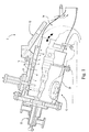
- FIGURE 1 is a partial cross-section of one section of a known gas turbine showing typical combustor components;
- FIGURE 2 is a cross-section of another section of the gas turbine, showing the turbine stages downstream of the combustor components shown in Figure 1;
- FIGURE 3 is a partial cross-section through a gas turbine nozzle in accordance with this invention; and
- FIGURE 4 is a graph plotting protective top coating thickness against TBC in-use temperature.
-
- A
typical gas turbine 2 includes a multi-stage compressor, multiple (e.g., six, ten, fourteen, etc.) combustors (oriented in a circular array about the rotor), with three or four turbine stages. As shown in Figure 1, eachcombustor 10 of theturbine 2 includes acombustion chamber 14 surrounded by a slot-cooledliner assembly 16 which, in turn, is enclosed partially within aflow sleeve 18. - The
liner assembly 16 andflow sleeve 18 are enclosed within acylindrical combustor casing 20. Afuel nozzle assembly 22 is mounted at the rear of thecasing 20, and supplies fuel to the combustion chamber. Compressor discharge air is supplied to the combustor for reverse flow between the flow sleeve and liner and into the combustion zone or chamber. Combustion gases are supplied to the turbine stages via transition pieces connected to each combustor. One such transition piece is indicated at 24. - Referring now to Figure 2, the turbine rotor, generally designated 26, is comprised of stacked elements, for example, the
rotor wheels spacers wheels Stationary nozzles - Figures 1 and 2 thus illustrate the various components in the hot gas path of the
turbine 2 that are candidates for the TBC and top coatings as described herein. - For simplicity, the present invention will be described in reference to a high pressure nozzle component (for example,
nozzle 50, as shown in Figure 2), but it will be understood that the invention is generally applicable to any component that operates within the hot gas path section of the turbine. Such components include rotating buckets or blades, combustion hardware including liners, transition pieces, combustion chamber caps, splash plates, etc. - The
nozzle 50 generally includes an airfoil portion against which hot combustion gases are directed during operation of the gas turbine engine, and whose surface is therefore subjected to severe attack by oxidation, hot corrosion and erosion. - Represented in Figure 3 is a thermal barrier coating (TBC)
system 58 of a type known in the art. As shown, the coating system includes abond coat 60 overlying asubstrate 56, which represents the base material of thenozzle 50. Suitable materials for thenozzle 50 include equiaxed, directionally-solidified and single-crystal nickel, iron and cobalt-base superalloys, as well as nonmetallic structural materials including ceramic matrix composite (CMC) materials. Thebond coat 60 may be an overlay coating such as MCrAIX (where M is iron, cobalt and/or nickel, and X is yttrium or another rare earth element), or a diffusion aluminide coating such as a platinum aluminide. Thebond coat 60 is shown as adhering a thermal barrier coating (TBC) 62 to thesubstrate 56. A preferred material for theTBC 62 is an yttria-stabilized zirconia (YSZ), a preferred composition being about 3 to about 8 weight percent yttria, though other ceramic materials could be used, such as alumina, nonstabilized zirconia, or zirconia partially or fully stabilized by magnesia, ceria, scandia or other oxides. - The
TBC 62 is depicted as having been deposited by air plasma spraying (APS), by which "splats" of molten material are deposited on thebond coat 60. As indicated, theTBC 62 has a degree of inhomogeneity and porosity that typically occurs in coatings produced by plasma spraying. In addition, the surface of theTBC 62 is relatively coarse, with a surface roughness of 200 to 500 microinches Ra (about 5 to 13 micrometers Ra) being typical for YSZ deposited by APS (APSTBC). While depositing theTBC 62 by APS is particularly suitable, other plasma spraying techniques could also be used, such as low pressure plasma spraying (LPPS; also known as vacuum plasma spraying (VPS)). TheTBC 62 is deposited to a thickness that is sufficient to provide the required thermal protection for theunderlying substrate 56 and airfoil portion thereof on the order of about 75 to about 500 micrometers. - While many TBC systems use YSZ deposited by APS as the outermost layer, drawbacks include the roughness of the TBC surface, erosion resistance, and transmissivity to infrared (IR) radiation. Within the operating environment of a gas turbine engine, surface roughness increases turbulent transfer from the hot combustion gases to the component and reduces aerodynamic performance. While surface roughness can be reduced by polishing, such as tumbling or hand polishing, the final surface finish and thickness of the TBC cannot be closely controlled and the additional processing costs are undesirable. Though crystalline YSZ is very resistant to erosion, the erosion resistance of a YSZ APSTBC is significantly reduced as a result of its porosity and "microcrack" structure, the result of which is that fine particle bombardment dislodges small pieces of the TBC. In regard to IR transmissivity, analysis has shown that YSZ is about 20% to 40% transparent to thermal radiation (wavelengths of about 780 mm to about 1 mm) when deposited by APS to thicknesses of about 250 to 500 micrometers. As a result, the thermal protection provided by YSZ APSTBC is compromised in environments that have high thermal radiation loads, such as within a gas turbine engine.
- To address the above concerns, the
TBC 62 in Figure 3 is overcoated by a protectivetop coating 64. As the outermost layer on thenozzle 44, theprotective coating 64 determines the surface roughness of the nozzle. The protectivetop coating 64 of this invention also serves as a barrier to thermal radiation and erosion. The protectivetop coating 64 achieves these features of the invention as a result of its thickness, composition and method of deposition. - The protective
top coating 64 is generally an alumina-base-silica-bound ceramic material. More particularly, the protectivetop coating 64 contains particles of alumina (Al2O3) that are dispersed within a binder matrix composed of silica (SiO2), silicates and/or mullite (3Al2O3 2SiO2), the relative amounts of which will vary depending on the firing temperature and subsequent service temperatures seen by thecoating 64, with greater amounts of mullite forming at higher temperatures. The alumina particles constitute at least 5 up to about 85 weight percent of the outer protectivetop coating 64, while the silica-containing binder matrix constitutes about 1 to about 45 weight percent of the protectivetop coating 64. The relative amounts of alumina and silica-based matrix material in the protectivetop coating 64 can be tailored depending on the desired properties. Higher silica contents depress the CTE of thecoating 64 and promote glass formation, while higher alumina contents have the generally preferred opposite effect, since a higher CTE reduces the CTE mismatch of the protectivetop coating 64 with ametallic substrate 58. Additional ceramic constituents for theprotective coating 64 include zirconia (particularly YSZ), zinc titanate, and glass materials if present in appropriately limited amounts. For example, additions of zirconia are beneficial to increase the CTE of thecoating 64, and additions of zinc titanate promote the reflectivity of thecoating 64 to thermal radiation. - The alumina particles may be present within the protective
top coating 64 in two discrete particle size ranges. If such a bimodal size distribution is used, a suitable particle size range for the coarser constituent is about 3.0 to about 6.0 micrometers in diameter, the particles of which constitute about 15 to about 55 weight percent of the protective coating. A preferred alumina powder for the coarser constituent has a particle size range of about 3.0 to about 5.5 micrometers in diameter. A suitable particle size range for the finer alumina particles of a bimodal powder is about 0.05 to about 0.8 micrometers in diameter, the particles of which constitute about 8 to about 45 weight percent of thecoating 64. A preferred alumina powder for the finer constituent has a particle size range of about 0.10 to about 0.6 micrometers in diameter. In the preferred size ranges, the finer particles are able to fill the spaces between the larger particles at the surface of theprotective coating 64 to achieve a surface roughness of not more than about 2.5 micrometers Ra, typically in the range of about 1.5 to 2.5 micrometers Ra (about 50 to 400/500 Ra), which is significantly smoother than that possible for theTBC 62 when deposited by APS (typically about 10 to 15 micrometers Ra(about 500 to 600 microinches Ra)). Another benefit of the bimodal size distribution of the alumina particles is that at very high temperatures, silica within the matrix of the protectivetop coating 64 preferentially reacts with the finer alumina particles to form a mullite phase. - Alumina powders for both the coarser and finer constituents are commercially available. For example, a suitable alumina powder for the coarser constituent is available under the designation A14 from ALCOA, which has a low soda content (NAO2 < 0.10 percent) and a surface area of about 0.5 m2/g. A suitable alumina powder for the finer constituent is available under the designation Baikalox SM8 from Baikowski International Corporation, and has a surface area of about 10 m2/g and an agglomerate size distribution (on a cumulative weight basis) of 65% below 0.3 micrometer, 78% below 0.4 micrometer, 95% below 0.6 micrometer, and 100% below 1.0 micrometer.
- To achieve the desired surface roughness of not more than 2.5 micrometers Ra, the protective
top coating 64 must be capable of being deposited in such a manner as to have a smoother surface finish than theunderlying TBC 62. In one embodiment, the protectivetop coating 64 is deposited by spraying a slurry that contains the alumina particles, a precursor of the silica-containing matrix, and a carrier liquid or solvent. A suitable precursor for the slurry is a silicone such as polymethyl siloxane, a particular example of which is a resin manufactured by GE Silicones under the name SR350, and classified as a methylsesquisiloxane mixture of the polysiloxane family. A suitable carrier liquid is an anhydrous alcohol such as methanol or ethanol, though acetone, isopropyl alcohol or trichloroethylene could be used. A suitable slurry contains about 40 to about 65 weight percent of the alumina powder (preferably having the two particle size ranges discussed above), about 1 to about 45 weight percent of the silica precursor, and about 5 to about 90 weight percent of the carrier liquid. An additional and optional constituent is zinc titanate in amounts of up to about 50 weight percent of the slurry to promote the reflectivity of thecoating 64 to thermal radiation. After being sprayed on theTBC 62 using any suitable sprayer known in the art, the composition can be dried at room temperature and then fired to yield a substantially homogeneousprotective coating 64 with a surface roughness in the range of about 40 to 150 microinches Ra (about 1 to about 3.8 micrometers Ra). The composition of the sprayedprotective coating 64 is preferably about 30 to about 55 weight percent of the coarser alumina, about 20 to about 40 weight percent of the finer alumina, up to about 30 weight percent zinc titanate (if present0, and about 25 to about 45 weight percent of the silica-containing matrix. - The outer layer of the protective
top coating 64 may contain, in addition to the alumina powder and silica precursor, a glass frit material and zinc titanate (Zn2TiO4), the latter of which promotes the reflectivity of the coating. - The thickness, structure and properties of the
protective coating 64 can be tailored by the firing temperature and duration used. Suitable thicknesses for the protective top coating may be in the range of about 25 to about 150 micrometers. In accordance with this invention, the thickness of theTBC 62 is preferably determined as a function of the operating or in-use temperature of the TBC as described below. Reference is now made to Figure 4 which illustrates in graph form the relationship between thickness of theTBC 62 and the operating temperature of the TBC designed to operate in use at temperature ranges of between about 1750°F and 2200°F. If, for example, the operating temperature of theTBC 62 is 2000°F, the minimum acceptable thickness for theTBC 62 would be about 5.5 mils. Thicknesses below the acceptable levels, i.e., under the curve, will result in spallation of the protectivetop coating 64 and possibly even failure of the component. To prevent spallation of the protectivetop coating 64, the thickness of theTBC 62 should be at least and preferably greater than the minimum effective thickness represented by the curve. It will be appreciated that suitable graphs may be developed for the various turbine components, depending on expected TBC temperatures. - For completeness, various aspects of the invention are set out in the following numbered clauses:
- 1. A turbine component (50) adapted for use in a hot gas path of a gas turbine having a thermal barrier coating (62) of predetermined thickness on at least one surface portion (56) thereof, said turbine component further comprising a protective top coating (64) applied over the thermal barrier coating, said predetermined thickness determined as a function of in-use temperature of the thermal barrier coating.
- 2. The turbine component of clause 1 wherein the turbine component (50) comprises a turbine nozzle.
- 3. The turbine component of clause 1 wherein said protective top coating (64) has a thickness in a range of from about 25 to about 160 micrometers.
- 4. The turbine component of clause 1 wherein said protective top coating (64) comprises alumina particles in a silica-containing matrix.
- 5. The turbine component of clause 1 including a bond coat (60) between said component and said thermal barrier coating.
- 6. The turbine component of clause 1 comprising a bucket (42) adapted to be secured to a turbine rotor.
- 7. The turbine component of clause 1 comprising a combustion liner (16).
- 8. The turbine component of clause 1 comprising a transition piece (24).
- 9. A component (50) having a thermal barrier coating (62) on a surface thereof, the component comprising an outer protective top coating (64) overlying the thermal barrier coating, the outer protective top coating comprising alumina particles in a silica-containing matrix, the alumina particles constituting about 5 to about 85 weight percent of the outer protective top coating, and the silica-containing matrix consisting essentially of at least one of silica, silicate, and mullite, and constituting about 1 to about 45 weight percent of the outer protective top coating; and wherein the thermal barrier coating has a thickness determined as a function of in-use temperature of the thermal barrier coating.
- 10. A component according to clause 9, wherein the outer protective top coating (64) further comprises at least one of a glass material, a zirconia-based material, and zinc titanate.
- 11. A component according to clause 9, wherein the outer protective top coating (64) comprises two particle size ranges of the alumina particles, a first of the two particle size ranges being about 3.0 to about 6.0 micrometers, and a second of the two particle size ranges being about 0.05 to about 0.8 micrometers.
- 12. A component according to clause 9, wherein the alumina particles within the first particle size range constitute about 15 to about 55 weight percent of the outer protective coating, and the alumina particles within the second particle size range constitute about 8 to about 45 weight percent of the outer protective top coating.
- 13. A component according to clause 9, wherein the outer protective top coating (64) has a thickness of about 25 to about 150 micrometers.
- 14. A component according to clause 9, comprising a stationary turbine nozzle (50).
- 15. A gas turbine engine component (50) having a thermal barrier coating (62) of partially-stabilized zirconia on a surface thereof, the component comprising an outer protective top coating (64) overlying the thermal barrier coating, the outer protective top coating comprising alumina particles in a binder matrix, the binder matrix consisting essentially of at least one of silica, silicate and mullite, the alumina particles constituting about 5 to about 85 weight percent of the outer protective top coating, the binder matrix constituting about 1 to about 45 weight percent of the outer protective top coating, the outer protective top coating having a surface roughness of not greater than 3.8 micrometers Ra, and wherein the thermal barrier coating has a thickness determined as a function of in-use temperature of the thermal barrier coating.
- 16. The turbine component of clause 15 including a bond coat (60) between said component and said thermal barrier coating.
- 17. The turbine component of clause 15 comprising a bucket (42) adapted to be secured to a turbine rotor.
- 18. The turbine component of clause 15 comprising a combustion liner (16).
- 19. The turbine component of clause 15 comprising a transition piece (24).
- 20. A component according to clause 15 comprising a stationary turbine nozzle (50).
- 21. A method of preventing spallation of a protective top coating (64) applied
over a thermal barrier coating (62) on a gas turbine engine component (50)
comprising:
- a. determining when spallation of the protective top coating (64) occurs as a function of minimum effective thickness and in-use temperature of the thermal barrier coating (62); and
- b. choosing a thickness for the thermal barrier coating (62) that is at least equal to said minimum effective thickness.
-
Claims (9)
- A component (50) having a thermal barrier coating (62) on a surface thereof, the component comprising an outer protective top coating (64) overlying the thermal barrier coating, the outer protective top coating comprising alumina particles in a silica-containing matrix, the alumina particles constituting about 5 to about 85 weight percent of the outer protective top coating, and the silica-containing matrix consisting essentially of at least one of silica, silicate, and mullite, and constituting about 1 to about 45 weight percent of the outer protective top coating; and wherein the thermal barrier coating has a thickness determined as a function of in-use temperature of the thermal barrier coating.
- A component according to claim 1, wherein the outer protective top coating (64) further comprises at least one of a glass material, a zirconia-based material, and zinc titanate.
- A component according to claim 1, wherein the outer protective top coating (64) comprises two particle size ranges of the alumina particles, a first of the two particle size ranges being about 3.0 to about 6.0 micrometers, and a second of the two particle size ranges being about 0.05 to about 0.8 micrometers.
- A component according to claim 1, wherein the alumina particles within the first particle size range constitute about 15 to about 55 weight percent of the outer protective coating, and the alumina particles within the second particle size range constitute about 8 to about 45 weight percent of the outer protective top coating.
- A component according to claim 1, wherein the outer protective top coating (64) has a thickness of about 25 to about 150 micrometers.
- A component according to claim 1, comprising a stationary turbine nozzle (50).
- A gas turbine engine component (50) having a thermal barrier coating (62) of partially-stabilized zirconia on a surface thereof, the component comprising an outer protective top coating (64) overlying the thermal barrier coating, the outer protective top coating comprising alumina particles in a binder matrix, the binder matrix consisting essentially of at least one of silica, silicate and mullite, the alumina particles constituting about 5 to about 85 weight percent of the outer protective top coating, the binder matrix constituting about 1 to about 45 weight percent of the outer protective top coating, the outer protective top coating having a surface roughness of not greater than 3.8 micrometers Ra, and wherein the thermal barrier coating has a thickness determined as a function of in-use temperature of the thermal barrier coating.
- The turbine component of claim 7 including a bond coat (60) between said component and said thermal barrier coating.
- A method of preventing spallation of a protective top coating (64) applied over a thermal barrier coating (62) on a gas turbine engine component (50) comprising:a. determining when spallation of the protective top coating (64) occurs as a function of minimum effective thickness and in-use temperature of the thermal barrier coating (62); andb. choosing a thickness for the thermal barrier coating (62) that is at least equal to said minimum effective thickness.
Applications Claiming Priority (2)
| Application Number | Priority Date | Filing Date | Title |
|---|---|---|---|
| US45578503A | 2003-06-06 | 2003-06-06 | |
| US455785 | 2003-06-06 |
Publications (2)
| Publication Number | Publication Date |
|---|---|
| EP1484427A2 true EP1484427A2 (en) | 2004-12-08 |
| EP1484427A3 EP1484427A3 (en) | 2005-10-26 |
Family
ID=33159569
Family Applications (1)
| Application Number | Title | Priority Date | Filing Date |
|---|---|---|---|
| EP04253222A Withdrawn EP1484427A3 (en) | 2003-06-06 | 2004-05-28 | Top coating system for industrial turbine nozzle airfoils and other hot gas path components and related method |
Country Status (4)
| Country | Link |
|---|---|
| EP (1) | EP1484427A3 (en) |
| JP (1) | JP2004360699A (en) |
| KR (1) | KR20040105570A (en) |
| CN (1) | CN100458104C (en) |
Cited By (16)
| Publication number | Priority date | Publication date | Assignee | Title |
|---|---|---|---|---|
| EP1609885A1 (en) * | 2004-06-18 | 2005-12-28 | General Electric Company | Smooth outer coating for combustor components and coating method therefor |
| EP1806423A1 (en) * | 2006-01-10 | 2007-07-11 | United Technologies Corporation | Thermal barrier coating compositions, processes for applying same and articles coated with same |
| CN1326803C (en) * | 2006-02-09 | 2007-07-18 | 沈阳黎明航空发动机(集团)有限责任公司 | Hollow cast ceramic core and its preparation method |
| EP1978210A1 (en) * | 2007-01-17 | 2008-10-08 | General Electric Company | Methods and apparatus for coating gas turbine engines |
| EP2062999A2 (en) * | 2007-10-29 | 2009-05-27 | General Electric Company | A method of treating a thermal barrier coating and related articles |
| KR101125329B1 (en) * | 2009-06-29 | 2012-03-27 | 한국전력공사 | Method for forming thermal barrier coating on hot-gas-path components of gas turbine during operation |
| WO2014023906A1 (en) * | 2012-08-07 | 2014-02-13 | Snecma | Abradable coating made of a material having a low surface roughness |
| EP2270313A3 (en) * | 2009-06-30 | 2015-07-22 | Mitsubishi Hitachi Power Systems, Ltd. | High-temperature resistant gas turbine component |
| FR3041631A1 (en) * | 2015-09-24 | 2017-03-31 | Snecma | POROUS CERAMIC COATING MATERIAL FOR COATING A WORKPIECE AND METHOD OF MANUFACTURING THE SAME |
| US20170107833A1 (en) * | 2014-06-25 | 2017-04-20 | Siemens Aktiengesellschaft | Gas turbine engine with a transition duct and corresponding method of manufacturing a transition duct |
| DE102015221751A1 (en) * | 2015-11-05 | 2017-05-11 | Siemens Aktiengesellschaft | Process for the preparation of a corrosion protection layer for thermal insulation layers of hollow aluminum oxide spheres and outermost glass layer and component and material mixture |
| US9803925B2 (en) | 2012-12-20 | 2017-10-31 | Plansee Se | Thermal shielding system |
| EP3556904A1 (en) * | 2018-04-17 | 2019-10-23 | General Electric Company | Reactive phase spray formulation coatings |
| US10927679B2 (en) | 2010-09-21 | 2021-02-23 | 8 Rivers Capital, Llc | High efficiency power production methods, assemblies, and systems |
| US20210131305A1 (en) * | 2019-11-06 | 2021-05-06 | General Electric Company | Restoration coating system and method |
| US11624288B2 (en) | 2018-01-09 | 2023-04-11 | General Electric Company | Slotted ceramic coating with a reactive phase coating disposed thereon for improved CMAS resistance and methods of forming the same |
Families Citing this family (12)
| Publication number | Priority date | Publication date | Assignee | Title |
|---|---|---|---|---|
| US20050282032A1 (en) * | 2004-06-18 | 2005-12-22 | General Electric Company | Smooth outer coating for combustor components and coating method therefor |
| US20060211241A1 (en) * | 2005-03-21 | 2006-09-21 | Christine Govern | Protective layer for barrier coating for silicon-containing substrate and process for preparing same |
| US7771159B2 (en) * | 2006-10-16 | 2010-08-10 | General Electric Company | High temperature seals and high temperature sealing systems |
| JP5215690B2 (en) * | 2008-03-06 | 2013-06-19 | 三菱重工業株式会社 | Thermal barrier coating structure, gas turbine high temperature parts, gas turbine |
| AU2012358959B2 (en) * | 2011-12-19 | 2018-02-08 | Praxair S.T. Technology, Inc. | Aqueous slurry for the production of thermal and environmental barrier coatings and processes for making and applying the same |
| JP5967974B2 (en) * | 2012-02-28 | 2016-08-10 | 三菱日立パワーシステムズ株式会社 | Pilot nozzle, gas turbine combustor including the same, and gas turbine |
| CN105063543A (en) * | 2015-08-13 | 2015-11-18 | 马鞍山蓝科再制造技术有限公司 | Inflaming retarding and oxidation resistance thermal barrier coating and manufacturing method thereof |
| CN105088124A (en) * | 2015-08-13 | 2015-11-25 | 马鞍山蓝科再制造技术有限公司 | Thermal barrier coating with high bonding strength and preparation method thereof |
| KR102429005B1 (en) * | 2016-12-02 | 2022-08-03 | 현대자동차 주식회사 | Munti-layered thermal insulation coating layer and preparing method for the same |
| KR102496794B1 (en) * | 2016-12-02 | 2023-02-06 | 현대자동차 주식회사 | Munti-layered thermal insulation coating layer and preparing method for the same |
| KR102238861B1 (en) * | 2017-05-11 | 2021-04-09 | 미츠비시 파워 가부시키가이샤 | Turbine casing thermal insulation device, turbine casing thermal insulation block fixing mechanism, and turbine casing thermal insulation block fixing method |
| US20230101282A1 (en) * | 2021-09-28 | 2023-03-30 | General Electric Company | Anti-corrosion coatings |
Citations (7)
| Publication number | Priority date | Publication date | Assignee | Title |
|---|---|---|---|---|
| EP0733723A1 (en) * | 1995-03-21 | 1996-09-25 | Howmet Corporation | Thermal barrier coating system |
| EP0783043A1 (en) * | 1996-01-02 | 1997-07-09 | General Electric Company | Thermal barrier coating resistant to erosion and impact by particulate matter |
| US6071628A (en) * | 1999-03-31 | 2000-06-06 | Lockheed Martin Energy Systems, Inc. | Thermal barrier coating for alloy systems |
| EP1088908A2 (en) * | 1999-10-01 | 2001-04-04 | General Electric Company | A method for smoothing the surface of a protective coating |
| WO2001083851A1 (en) * | 2000-04-27 | 2001-11-08 | Standard Aero Limited | Multilayer thermal barrier coatings |
| EP1225251A2 (en) * | 2001-01-18 | 2002-07-24 | General Electric Company | Thermally-stabilized thermal barrier coating |
| EP1335040A2 (en) * | 2002-02-11 | 2003-08-13 | General Electric Company | Method of forming a coating resistant to deposits and coating formed thereby |
Family Cites Families (1)
| Publication number | Priority date | Publication date | Assignee | Title |
|---|---|---|---|---|
| US5366765A (en) * | 1993-05-17 | 1994-11-22 | United Technologies Corporation | Aqueous slurry coating system for aluminide coatings |
-
2004
- 2004-05-28 EP EP04253222A patent/EP1484427A3/en not_active Withdrawn
- 2004-06-04 CN CNB2004100452679A patent/CN100458104C/en not_active Expired - Fee Related
- 2004-06-04 KR KR1020040040988A patent/KR20040105570A/en not_active Application Discontinuation
- 2004-06-04 JP JP2004167145A patent/JP2004360699A/en not_active Withdrawn
Patent Citations (7)
| Publication number | Priority date | Publication date | Assignee | Title |
|---|---|---|---|---|
| EP0733723A1 (en) * | 1995-03-21 | 1996-09-25 | Howmet Corporation | Thermal barrier coating system |
| EP0783043A1 (en) * | 1996-01-02 | 1997-07-09 | General Electric Company | Thermal barrier coating resistant to erosion and impact by particulate matter |
| US6071628A (en) * | 1999-03-31 | 2000-06-06 | Lockheed Martin Energy Systems, Inc. | Thermal barrier coating for alloy systems |
| EP1088908A2 (en) * | 1999-10-01 | 2001-04-04 | General Electric Company | A method for smoothing the surface of a protective coating |
| WO2001083851A1 (en) * | 2000-04-27 | 2001-11-08 | Standard Aero Limited | Multilayer thermal barrier coatings |
| EP1225251A2 (en) * | 2001-01-18 | 2002-07-24 | General Electric Company | Thermally-stabilized thermal barrier coating |
| EP1335040A2 (en) * | 2002-02-11 | 2003-08-13 | General Electric Company | Method of forming a coating resistant to deposits and coating formed thereby |
Cited By (26)
| Publication number | Priority date | Publication date | Assignee | Title |
|---|---|---|---|---|
| US7368164B2 (en) | 2004-06-18 | 2008-05-06 | General Electric Company | Smooth outer coating for combustor components and coating method therefor |
| EP1609885A1 (en) * | 2004-06-18 | 2005-12-28 | General Electric Company | Smooth outer coating for combustor components and coating method therefor |
| US8529999B2 (en) | 2006-01-10 | 2013-09-10 | United Technologies Corporation | Thermal barrier coating application processes |
| EP1806423A1 (en) * | 2006-01-10 | 2007-07-11 | United Technologies Corporation | Thermal barrier coating compositions, processes for applying same and articles coated with same |
| CN1326803C (en) * | 2006-02-09 | 2007-07-18 | 沈阳黎明航空发动机(集团)有限责任公司 | Hollow cast ceramic core and its preparation method |
| EP1978210A1 (en) * | 2007-01-17 | 2008-10-08 | General Electric Company | Methods and apparatus for coating gas turbine engines |
| EP2062999A3 (en) * | 2007-10-29 | 2012-01-25 | General Electric Company | A method of treating a thermal barrier coating and related articles |
| EP2062999A2 (en) * | 2007-10-29 | 2009-05-27 | General Electric Company | A method of treating a thermal barrier coating and related articles |
| KR101125329B1 (en) * | 2009-06-29 | 2012-03-27 | 한국전력공사 | Method for forming thermal barrier coating on hot-gas-path components of gas turbine during operation |
| EP2270313A3 (en) * | 2009-06-30 | 2015-07-22 | Mitsubishi Hitachi Power Systems, Ltd. | High-temperature resistant gas turbine component |
| US11859496B2 (en) | 2010-09-21 | 2024-01-02 | 8 Rivers Capital, Llc | High efficiency power production methods, assemblies, and systems |
| US11459896B2 (en) | 2010-09-21 | 2022-10-04 | 8 Rivers Capital, Llc | High efficiency power production methods, assemblies, and systems |
| US10927679B2 (en) | 2010-09-21 | 2021-02-23 | 8 Rivers Capital, Llc | High efficiency power production methods, assemblies, and systems |
| WO2014023906A1 (en) * | 2012-08-07 | 2014-02-13 | Snecma | Abradable coating made of a material having a low surface roughness |
| FR2994397A1 (en) * | 2012-08-07 | 2014-02-14 | Snecma | COATING IN ABRADABLE MATERIAL WITH LOW SURFACE ROUGHNESS |
| US10989066B2 (en) | 2012-08-07 | 2021-04-27 | Safran Aircraft Engines | Abradable coating made of a material having a low surface roughness |
| US10385725B2 (en) | 2012-08-07 | 2019-08-20 | Safran Aircraft Engines | Abradable coating made of a material having a low surface roughness |
| US9803925B2 (en) | 2012-12-20 | 2017-10-31 | Plansee Se | Thermal shielding system |
| US10704402B2 (en) * | 2014-06-25 | 2020-07-07 | Siemens Aktiengesellschaft | Gas turbine engine with a transition duct and corresponding method of manufacturing a transition duct |
| US20170107833A1 (en) * | 2014-06-25 | 2017-04-20 | Siemens Aktiengesellschaft | Gas turbine engine with a transition duct and corresponding method of manufacturing a transition duct |
| FR3041631A1 (en) * | 2015-09-24 | 2017-03-31 | Snecma | POROUS CERAMIC COATING MATERIAL FOR COATING A WORKPIECE AND METHOD OF MANUFACTURING THE SAME |
| DE102015221751A1 (en) * | 2015-11-05 | 2017-05-11 | Siemens Aktiengesellschaft | Process for the preparation of a corrosion protection layer for thermal insulation layers of hollow aluminum oxide spheres and outermost glass layer and component and material mixture |
| US11624288B2 (en) | 2018-01-09 | 2023-04-11 | General Electric Company | Slotted ceramic coating with a reactive phase coating disposed thereon for improved CMAS resistance and methods of forming the same |
| EP3556904A1 (en) * | 2018-04-17 | 2019-10-23 | General Electric Company | Reactive phase spray formulation coatings |
| US20210131305A1 (en) * | 2019-11-06 | 2021-05-06 | General Electric Company | Restoration coating system and method |
| US11549382B2 (en) * | 2019-11-06 | 2023-01-10 | General Electric Company | Restoration coating system and method |
Also Published As
| Publication number | Publication date |
|---|---|
| EP1484427A3 (en) | 2005-10-26 |
| JP2004360699A (en) | 2004-12-24 |
| CN1584297A (en) | 2005-02-23 |
| KR20040105570A (en) | 2004-12-16 |
| CN100458104C (en) | 2009-02-04 |
Similar Documents
| Publication | Publication Date | Title |
|---|---|---|
| EP1484427A2 (en) | Top coating system for industrial turbine nozzle airfoils and other hot gas path components and related method | |
| EP1609885B1 (en) | Coating method for smooth outer coating for combustor components | |
| US6465090B1 (en) | Protective coating for thermal barrier coatings and coating method therefor | |
| US7833586B2 (en) | Alumina-based protective coatings for thermal barrier coatings | |
| US6558814B2 (en) | Low thermal conductivity thermal barrier coating system and method therefor | |
| US7862901B2 (en) | Yttria containing thermal barrier coating topcoat layer and method for applying the coating layer | |
| EP1798311B1 (en) | Strain tolerant corrosion protecting coating | |
| EP1153157B1 (en) | Thermal barrier coating resistant to sintering | |
| EP2298951B1 (en) | Composition and method for a thermal coating system | |
| CA2785264A1 (en) | Methods for coating articles exposed to hot and harsh environments | |
| CA3040347A1 (en) | Method for coating a surface of a solid substrate with a layer comprising a ceramic compound, and coated substrate thus obtained | |
| US7090894B2 (en) | Bondcoat for the application of TBC's and wear coatings to oxide ceramic matrix | |
| EP2767525B1 (en) | Ceramic powders and methods therefor | |
| EP3748031B1 (en) | Reflective coating and coating process therefor | |
| EP2778250A2 (en) | Coating systems and methods therefor | |
| EP1789606A1 (en) | Smooth outer coating for combustor components and coating method therefor | |
| US20050100757A1 (en) | Thermal barrier coating having a heat radiation absorbing topcoat |
Legal Events
| Date | Code | Title | Description |
|---|---|---|---|
| PUAI | Public reference made under article 153(3) epc to a published international application that has entered the european phase |
Free format text: ORIGINAL CODE: 0009012 |
|
| AK | Designated contracting states |
Kind code of ref document: A2 Designated state(s): AT BE BG CH CY CZ DE DK EE ES FI FR GB GR HU IE IT LI LU MC NL PL PT RO SE SI SK TR |
|
| AX | Request for extension of the european patent |
Extension state: AL HR LT LV MK |
|
| RIN1 | Information on inventor provided before grant (corrected) |
Inventor name: SEAL, MICHAEL DAMIAN Inventor name: DEBELLIS, LISA Inventor name: ROLING, MATHEW CURTIS Inventor name: ARNESS, BRIAN P. Inventor name: MEYER, ROBERT CARL Inventor name: MCGOVERN, TARA E. Inventor name: ROWE, RAYMOND GRANT Inventor name: MURPHY, JANE ANN Inventor name: STOWELL, WILLIAM R. Inventor name: BRUCE, KEVIN LEON Inventor name: CLARE, JAMES H. Inventor name: SKOOG, ANDREW JAY Inventor name: MARKS, PAUL THOMAS |
|
| PUAL | Search report despatched |
Free format text: ORIGINAL CODE: 0009013 |
|
| AK | Designated contracting states |
Kind code of ref document: A3 Designated state(s): AT BE BG CH CY CZ DE DK EE ES FI FR GB GR HU IE IT LI LU MC NL PL PT RO SE SI SK TR |
|
| AX | Request for extension of the european patent |
Extension state: AL HR LT LV MK |
|
| 17P | Request for examination filed |
Effective date: 20060426 |
|
| AKX | Designation fees paid |
Designated state(s): CH DE FR GB LI |
|
| 17Q | First examination report despatched |
Effective date: 20060906 |
|
| STAA | Information on the status of an ep patent application or granted ep patent |
Free format text: STATUS: THE APPLICATION IS DEEMED TO BE WITHDRAWN |
|
| 18D | Application deemed to be withdrawn |
Effective date: 20091201 |