EP1609885A1 - Smooth outer coating for combustor components and coating method therefor - Google Patents
Smooth outer coating for combustor components and coating method therefor Download PDFInfo
- Publication number
- EP1609885A1 EP1609885A1 EP05253749A EP05253749A EP1609885A1 EP 1609885 A1 EP1609885 A1 EP 1609885A1 EP 05253749 A EP05253749 A EP 05253749A EP 05253749 A EP05253749 A EP 05253749A EP 1609885 A1 EP1609885 A1 EP 1609885A1
- Authority
- EP
- European Patent Office
- Prior art keywords
- component
- silica
- coating
- alumina
- weight percent
- Prior art date
- Legal status (The legal status is an assumption and is not a legal conclusion. Google has not performed a legal analysis and makes no representation as to the accuracy of the status listed.)
- Granted
Links
Images

Classifications
-
- C—CHEMISTRY; METALLURGY
- C23—COATING METALLIC MATERIAL; COATING MATERIAL WITH METALLIC MATERIAL; CHEMICAL SURFACE TREATMENT; DIFFUSION TREATMENT OF METALLIC MATERIAL; COATING BY VACUUM EVAPORATION, BY SPUTTERING, BY ION IMPLANTATION OR BY CHEMICAL VAPOUR DEPOSITION, IN GENERAL; INHIBITING CORROSION OF METALLIC MATERIAL OR INCRUSTATION IN GENERAL
- C23C—COATING METALLIC MATERIAL; COATING MATERIAL WITH METALLIC MATERIAL; SURFACE TREATMENT OF METALLIC MATERIAL BY DIFFUSION INTO THE SURFACE, BY CHEMICAL CONVERSION OR SUBSTITUTION; COATING BY VACUUM EVAPORATION, BY SPUTTERING, BY ION IMPLANTATION OR BY CHEMICAL VAPOUR DEPOSITION, IN GENERAL
- C23C24/00—Coating starting from inorganic powder
- C23C24/08—Coating starting from inorganic powder by application of heat or pressure and heat
-
- C—CHEMISTRY; METALLURGY
- C23—COATING METALLIC MATERIAL; COATING MATERIAL WITH METALLIC MATERIAL; CHEMICAL SURFACE TREATMENT; DIFFUSION TREATMENT OF METALLIC MATERIAL; COATING BY VACUUM EVAPORATION, BY SPUTTERING, BY ION IMPLANTATION OR BY CHEMICAL VAPOUR DEPOSITION, IN GENERAL; INHIBITING CORROSION OF METALLIC MATERIAL OR INCRUSTATION IN GENERAL
- C23C—COATING METALLIC MATERIAL; COATING MATERIAL WITH METALLIC MATERIAL; SURFACE TREATMENT OF METALLIC MATERIAL BY DIFFUSION INTO THE SURFACE, BY CHEMICAL CONVERSION OR SUBSTITUTION; COATING BY VACUUM EVAPORATION, BY SPUTTERING, BY ION IMPLANTATION OR BY CHEMICAL VAPOUR DEPOSITION, IN GENERAL
- C23C28/00—Coating for obtaining at least two superposed coatings either by methods not provided for in a single one of groups C23C2/00 - C23C26/00 or by combinations of methods provided for in subclasses C23C and C25C or C25D
- C23C28/30—Coatings combining at least one metallic layer and at least one inorganic non-metallic layer
- C23C28/32—Coatings combining at least one metallic layer and at least one inorganic non-metallic layer including at least one pure metallic layer
- C23C28/321—Coatings combining at least one metallic layer and at least one inorganic non-metallic layer including at least one pure metallic layer with at least one metal alloy layer
- C23C28/3215—Coatings combining at least one metallic layer and at least one inorganic non-metallic layer including at least one pure metallic layer with at least one metal alloy layer at least one MCrAlX layer
-
- C—CHEMISTRY; METALLURGY
- C23—COATING METALLIC MATERIAL; COATING MATERIAL WITH METALLIC MATERIAL; CHEMICAL SURFACE TREATMENT; DIFFUSION TREATMENT OF METALLIC MATERIAL; COATING BY VACUUM EVAPORATION, BY SPUTTERING, BY ION IMPLANTATION OR BY CHEMICAL VAPOUR DEPOSITION, IN GENERAL; INHIBITING CORROSION OF METALLIC MATERIAL OR INCRUSTATION IN GENERAL
- C23C—COATING METALLIC MATERIAL; COATING MATERIAL WITH METALLIC MATERIAL; SURFACE TREATMENT OF METALLIC MATERIAL BY DIFFUSION INTO THE SURFACE, BY CHEMICAL CONVERSION OR SUBSTITUTION; COATING BY VACUUM EVAPORATION, BY SPUTTERING, BY ION IMPLANTATION OR BY CHEMICAL VAPOUR DEPOSITION, IN GENERAL
- C23C28/00—Coating for obtaining at least two superposed coatings either by methods not provided for in a single one of groups C23C2/00 - C23C26/00 or by combinations of methods provided for in subclasses C23C and C25C or C25D
- C23C28/30—Coatings combining at least one metallic layer and at least one inorganic non-metallic layer
- C23C28/32—Coatings combining at least one metallic layer and at least one inorganic non-metallic layer including at least one pure metallic layer
- C23C28/324—Coatings combining at least one metallic layer and at least one inorganic non-metallic layer including at least one pure metallic layer with at least one metal matrix material layer comprising a mixture of at least two metals or metal phases or a metal-matrix material with hard embedded particles, e.g. WC-Me
-
- C—CHEMISTRY; METALLURGY
- C23—COATING METALLIC MATERIAL; COATING MATERIAL WITH METALLIC MATERIAL; CHEMICAL SURFACE TREATMENT; DIFFUSION TREATMENT OF METALLIC MATERIAL; COATING BY VACUUM EVAPORATION, BY SPUTTERING, BY ION IMPLANTATION OR BY CHEMICAL VAPOUR DEPOSITION, IN GENERAL; INHIBITING CORROSION OF METALLIC MATERIAL OR INCRUSTATION IN GENERAL
- C23C—COATING METALLIC MATERIAL; COATING MATERIAL WITH METALLIC MATERIAL; SURFACE TREATMENT OF METALLIC MATERIAL BY DIFFUSION INTO THE SURFACE, BY CHEMICAL CONVERSION OR SUBSTITUTION; COATING BY VACUUM EVAPORATION, BY SPUTTERING, BY ION IMPLANTATION OR BY CHEMICAL VAPOUR DEPOSITION, IN GENERAL
- C23C28/00—Coating for obtaining at least two superposed coatings either by methods not provided for in a single one of groups C23C2/00 - C23C26/00 or by combinations of methods provided for in subclasses C23C and C25C or C25D
- C23C28/30—Coatings combining at least one metallic layer and at least one inorganic non-metallic layer
- C23C28/34—Coatings combining at least one metallic layer and at least one inorganic non-metallic layer including at least one inorganic non-metallic material layer, e.g. metal carbide, nitride, boride, silicide layer and their mixtures, enamels, phosphates and sulphates
- C23C28/345—Coatings combining at least one metallic layer and at least one inorganic non-metallic layer including at least one inorganic non-metallic material layer, e.g. metal carbide, nitride, boride, silicide layer and their mixtures, enamels, phosphates and sulphates with at least one oxide layer
- C23C28/3455—Coatings combining at least one metallic layer and at least one inorganic non-metallic layer including at least one inorganic non-metallic material layer, e.g. metal carbide, nitride, boride, silicide layer and their mixtures, enamels, phosphates and sulphates with at least one oxide layer with a refractory ceramic layer, e.g. refractory metal oxide, ZrO2, rare earth oxides or a thermal barrier system comprising at least one refractory oxide layer
-
- Y—GENERAL TAGGING OF NEW TECHNOLOGICAL DEVELOPMENTS; GENERAL TAGGING OF CROSS-SECTIONAL TECHNOLOGIES SPANNING OVER SEVERAL SECTIONS OF THE IPC; TECHNICAL SUBJECTS COVERED BY FORMER USPC CROSS-REFERENCE ART COLLECTIONS [XRACs] AND DIGESTS
- Y02—TECHNOLOGIES OR APPLICATIONS FOR MITIGATION OR ADAPTATION AGAINST CLIMATE CHANGE
- Y02T—CLIMATE CHANGE MITIGATION TECHNOLOGIES RELATED TO TRANSPORTATION
- Y02T50/00—Aeronautics or air transport
- Y02T50/60—Efficient propulsion technologies, e.g. for aircraft
-
- Y—GENERAL TAGGING OF NEW TECHNOLOGICAL DEVELOPMENTS; GENERAL TAGGING OF CROSS-SECTIONAL TECHNOLOGIES SPANNING OVER SEVERAL SECTIONS OF THE IPC; TECHNICAL SUBJECTS COVERED BY FORMER USPC CROSS-REFERENCE ART COLLECTIONS [XRACs] AND DIGESTS
- Y10—TECHNICAL SUBJECTS COVERED BY FORMER USPC
- Y10T—TECHNICAL SUBJECTS COVERED BY FORMER US CLASSIFICATION
- Y10T428/00—Stock material or miscellaneous articles
- Y10T428/25—Web or sheet containing structurally defined element or component and including a second component containing structurally defined particles
- Y10T428/252—Glass or ceramic [i.e., fired or glazed clay, cement, etc.] [porcelain, quartz, etc.]
-
- Y—GENERAL TAGGING OF NEW TECHNOLOGICAL DEVELOPMENTS; GENERAL TAGGING OF CROSS-SECTIONAL TECHNOLOGIES SPANNING OVER SEVERAL SECTIONS OF THE IPC; TECHNICAL SUBJECTS COVERED BY FORMER USPC CROSS-REFERENCE ART COLLECTIONS [XRACs] AND DIGESTS
- Y10—TECHNICAL SUBJECTS COVERED BY FORMER USPC
- Y10T—TECHNICAL SUBJECTS COVERED BY FORMER US CLASSIFICATION
- Y10T428/00—Stock material or miscellaneous articles
- Y10T428/25—Web or sheet containing structurally defined element or component and including a second component containing structurally defined particles
- Y10T428/256—Heavy metal or aluminum or compound thereof
Definitions
- the present invention generally relates to coatings for components exposed to high temperatures, such as the hostile thermal environment of a gas turbine. More particularly, this invention relates to a smooth outer coating for combustor components of a gas turbine component, in which the coating reduces the component temperature by reducing the convective and radiant heat transfer to the component in the combustor section of the turbine.
- TBC thermal barrier coating
- Ceramic materials and particularly yttria-stabilized zirconia (YSZ) are widely used as TBC materials because of their high temperature capability, low thermal conductivity, and relative ease of deposition by plasma spraying, flame spraying and physical vapor deposition (PVD) techniques.
- Air plasma spraying (APS) is often preferred over other deposition processes due to relatively low equipment costs and ease of application and masking.
- TBC's deposited by APS are characterized by a degree of inhomogeneity and porosity that occurs as a result of the deposition process, in which "splats" of molten material are deposited and subsequently solidify.
- the resulting surface of the TBC is relatively rough, with a surface roughness of 250 to 350 microinches Ra (about 6 to 9 micrometers Ra) being typical for YSZ deposited by APS (APSTBC).
- the inhomogeneity and porosity of a plasma-sprayed TBC enhances the thermal insulating property of the TBC, and thus helps to reduce the temperature of the component on which the TBC is deposited.
- APSTBC In regard to infrared (IR) transmissivity, analysis has shown that APSTBC is about 20% to 70% transparent to thermal radiation (wavelengths of about 780 nm to about 1 mm) when deposited at typically thicknesses of about 250 to 500 micrometers. As a result, the thermal protection provided by APSTBC is compromised in environments that have high thermal radiation loads, such as within the combustor section of a gas turbine.
- TBC systems must strongly adhere to the component and remain adherent throughout many heating and cooling cycles. The latter requirement is particularly demanding due to the different coefficients of thermal expansion (CTE) between ceramic materials and the substrates they protect, which are typically superalloys though ceramic matrix composite (CMC) materials are also used.
- CTE coefficients of thermal expansion
- CMC ceramic matrix composite
- Bond coats are typically in the form of an overlay coating such as MCrAIX (where M is iron, cobalt and/or nickel, and X is yttrium or another rare earth element), or a diffusion aluminide coating. During the deposition of the ceramic TBC and subsequent exposures to high temperatures, such as during turbine operation, these bond coats form a tightly adherent alumina (Al 2 O 3 ) layer or scale that adheres the TBC to the bond coat.
- the service life of a TBC system is typically limited by a spallation event brought on by thermal fatigue.
- spallation can be promoted as a result of the TBC being subjected to substances within the hot gas path of a gas turbine.
- spallation of TBC from combustor components such as liners, heatshields and transition pieces can be accelerated in industrial gas turbines that burn liquid fuel or utilize water injection for NOx abatement.
- the present invention generally provides a coating and method for overcoating a TBC on a component used in a high-temperature environment, such as the combustor section of a gas turbine.
- the invention is particularly directed to a coating that reduces the component temperature by reducing the convective and radiant heat transfer to the component in the combustor section of an industrial gas turbine.
- the coating of this invention defines the outermost surface of the component it protects, and is formed of at least two layers having different compositions.
- An inner layer of the coating contains first and second alumina particles in a first silica-containing matrix material that is free of zinc titanate and consists essentially of silica, silicate and/or mullite.
- the first alumina particles have a particle size that is coarser than the second alumina particles.
- An outer layer of the coating contains third alumina particles having a particle size distribution finer than the first and second alumina particles, a glass material, and zinc titanate in a second silica-containing matrix material consisting essentially of silica, silicate and/or mullite.
- the outer layer of the coating has a surface roughness of not greater than 120 microinches Ra (about 3 micrometers Ra) and, as the outermost surface of the component, is subjected to the hot combustion gases within the combustor section.
- the method of this invention involves preparing first and second slurries from which the inner and outer layers of the coating are formed.
- the first slurry is free of zinc titanate and contains the first and second alumina particles in a first silica-forming binder material, while the second slurry contains the third alumina particles, glass material, and zinc titanate in a second silica-forming binder material.
- the first slurry is deposited on the thermal barrier coating after which the second slurry is deposited on the inner layer.
- the slurry layers formed by the first and second slurries are fired to form the inner and outer layers, respectively, of the coating, with the outer layer defining the outermost surface of the component.
- the coating of this invention reduces the component temperature by reducing the convective and radiant heat transfer to the component.
- the fine particle size distribution of the outer layer enables the outermost surface defined by the outer layer to be sufficiently smooth to significantly reduce convective heat transfer to the component, and the zinc titanate contained in the outer layer serves to reduce the IR transmissivity of the coating.
- the bimodal particle size distribution of the inner layer promotes the chemical inertness and stability of the inner layer.
- the inner layer is chemically compatible with the outer layer and the absence of zinc titanate in the inner layer promotes the adhesion of the outer layer to the component.
- the coating of this invention improves the spallation and erosion resistance of the TBC, and is therefore capable of significantly extending the life of the gas turbine component protected by the thermal barrier coating.
- the present invention will be described in reference to a combustor 12 of an industrial gas turbine 10, a portion of which is shown in cross-section in Figure 1.
- the combustor 12 is one of multiple can-annular combustors located about the periphery of the turbine 10, and has a can-type liner 14 whose interior defines a combustion chamber of the turbine 10.
- the liner 14 is inserted into a transition piece 18 with multiple fuel nozzle assemblies 16 located at the head end of the liner 14. Both fuel and water may be injected into the combustion chamber through the nozzle assemblies 16, with the injection of water being for the purpose of reducing combustion temperatures and consequently NOx emissions.
- the invention is not limited to combustors having the configuration shown in Figure 1, but instead is applicable to other combustor configurations, such as the well-known annular type.
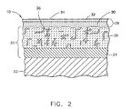
- a thermal barrier coating (TBC) system 20 of a type suitable for thermally insulating the interior surfaces of the liner 14 is represented in cross-section in Figure 2.
- the TBC system 20 includes a bond coat 24 overlying a substrate 22, which is typically but not necessarily the base material of the liner 14.
- Suitable materials for the substrate 22 (and therefore the liner 14) include nickel, iron and cobalt-base superalloys, as well as nonmetallic structural materials including ceramic matrix composite (CMC) materials.
- the TBC system 20 further includes a thermal barrier coating, hereinafter TBC 26, that provides the thermal protection for the substrate 22.
- a preferred material for the TBC 26 is an yttria-stabilized zirconia (YSZ), a preferred composition being about 3 to about 8 weight percent yttria, though other ceramic materials could be used, such as alumina, nonstabilized zirconia, or zirconia partially or fully stabilized by magnesia, ceria, scandia or other oxides.
- the bond coat 24 may be an overlay coating such as MCrAlX (where M is iron, cobalt and/or nickel, and X is yttrium or another rare earth element), or a diffusion aluminide coating such as a platinum aluminide.
- the TBC 26 is depicted as having been deposited by air plasma spraying (APS), by which "splats" of molten material are deposited on the bond coat 24. As indicated, the TBC 26 has a degree of inhomogeneity and porosity that typically occurs in coatings produced by plasma spraying. In addition, the surface of the TBC 26 is relatively rough, with a surface roughness of about 200 to 500 microinches Ra (about 5 to 13 micrometers Ra) being typical for YSZ deposited by APS (APSTBC). While depositing the TBC 26 by APS is of particular interest to this invention, other plasma spraying techniques could also be used, such as low pressure plasma spraying (LPPS; also known as vacuum plasma spraying (VPS)). The TBC 26 is deposited to a thickness that is sufficient to provide the required thermal protection for the underlying substrate 22 and liner 14.
- LPPS low pressure plasma spraying
- VPS vacuum plasma spraying
- the bond coat 24 is preferably an NiCrAlY overlay coating and the TBC 26 is zirconia stabilized by about eight weight percent yttria (8%YSZ).
- the bond coat 24 is preferably deposited by APS to a thickness of about 0.007 to about 0.010 inch (about 175 to about 250 micrometers) and has an average surface roughness R a of at least about 320 microinches (about 8 microinches) to promote adhesion of the TBC 26.
- the TBC 26 is depicted as having a construction disclosed in commonly-assigned U.S. Patent No.
- the TBC 26 has vertical microcracks 36 that extend through at least one-half the thickness of the TBC 26, and the density of the TBC 26 is preferably at least 90% of theoretical, i.e., contains less than 10% porosity by volume and more preferably less than 8% porosity by volume.
- a suitable thickness for the TBC is about 760 to about 2500 micrometers.
- TBC systems use YSZ deposited by APS as the outermost layer
- drawbacks include the roughness of the TBC surface, erosion resistance, and transmissivity to infrared (IR) radiation.
- IR infrared
- surface roughness increases turbulent heat transfer from the hot combustion gases to the component and reduces aerodynamic performance.
- surface roughness can be reduced by polishing, such as tumbling or hand polishing, the final surface finish and thickness of the TBC cannot be closely controlled and the additional processing costs are undesirable.
- crystalline YSZ is very resistant to erosion
- the erosion resistance of a YSZ APSTBC is significantly reduced as a result of its porosity and microcrack structure, the result of which is that fine particle bombardment dislodges small pieces of the TBC.
- IR transmissivity analysis has shown that YSZ is about 20% to 70% transparent to thermal radiation (wavelengths of about 780 nm to about 1 mm) when deposited by APS to thicknesses of about 250 to 500 micrometers.
- the thermal protection provided by YSZ APSTBC is compromised in environments that have high thermal radiation loads, such as within the combustor 10 of Figure 1.
- CMAS susceptibility of YSZ TBC's to attack by CMAS, which is a relatively low melting eutectic that when molten is able to infiltrate conventional TBC and promote spallation during thermal cycling.
- the TBC 26 in Figure 2 is overcoated by a multilayer outer coating 28.
- the coating 28 defines the outermost surface 34 of the liner 14 and therefore also determines the surface roughness of the liner 14.
- the outer coating 28 of this invention is also tailored to serve as a barrier to thermal radiation, while also having the advantage of being more resistant to erosion and CMAS infiltration than the TBC 26.
- the outer coating 28 achieves these features of the invention as a result of its composition and methods of deposition as described below.
- the outer coating 28 is generally an alumina-base silica-bound ceramic material. More particularly, the outer coating 28 contains alumina (Al 2 O 3 ) dispersed within a binder matrix material composed of silica (SiO 2 ), silicates and/or mullite (3Al 2 O 3 ⁇ 2SiO 2 ), the relative amounts of which will vary depending on the firing temperature and subsequent service temperatures seen by the coating 28, with greater amounts of mullite forming at higher temperatures.
- the coating 28 is depicted as comprising an inner layer 30 contacting the TBC 26 and an outer layer 32 defining the outermost surface 34, with the combined thicknesses of the layers 30 and 32 being less than that of the TBC 26.
- the compositions of the layers 30 and 32 are tailored for their particular function.
- the inner layer 30 is preferably limited to containing alumina in a silica matrix material, while the outer layer 32 includes alumina as well as a glass and zinc titanate (Zn 2 TiO 4 ) in a silica matrix material. While alumina is the preferred constituent of the coating 28, up to about 65 percent by weight of the alumina could be replaced by other metal oxides, such as zirconia (ZrO 2 ), magnesia (MgO), titania (TiO 2 ), or mullite.
- ZrO 2 zirconia
- MgO magnesia
- TiO 2 titania
- mullite mullite
- a more particular composition for the inner layer 30 contains about 5 to about 85 weight percent alumina, more preferably 40 to about 60 weight percent alumina, with the balance being essentially the silica matrix material.
- the inner layer 30 is deposited on the TBC 26 in the form of a slurry that is subsequently dried and fired.
- the slurry is preferably formulated to contain alumina particles in two discrete particle size ranges.
- a suitable particle size range for the coarser constituent is about 3.0 to about 6.0 micrometers in diameter.
- a preferred alumina powder for the coarser constituent has a particle size range of about 3.0 to about 5.5 micrometers in diameter, and is commercially available under the designation A-14 from ALCOA.
- a suitable particle size range for the finer alumina particles is about 0.05 to about 0.8 micrometers in diameter.
- a preferred alumina powder for the finer constituent has a particle size range of about 0.10 to about 0.6 micrometers in diameter, and is commercially available under the designation Baikalox SM8 from Baikowski International Corporation.
- the SM8 material has an agglomerate size distribution (on a cumulative weight basis) of 65% below 0.3 micrometer, 78% below 0.4 micrometer, 95% below 0.6 micrometer, and 100% below 1.0 micrometer.
- the finer particles are able to fill the spaces between the larger particles at the surface of the inner layer 30 to reduce its surface roughness.
- Another benefit of the bimodal size distribution of the alumina particles is that at very high temperatures, silica within the matrix material of the inner layer 30 preferentially reacts with the finer alumina particles to form a mullite phase.
- the slurry is prepared by combining the alumina powders with a silica precursor and a sufficient amount of carrier liquid to enable the slurry to be applied by spraying.
- a suitable precursor for the slurry is a silicone such as polymethyl siloxane, a particular example of which is a resin manufactured by GE Silicones under the name SR350, and classified as a methylsesquisiloxane mixture of the polysiloxane family.
- a suitable carrier liquid is an anhydrous alcohol such as methanol or ethanol, though acetone, isopropyl alcohol or trichloroethylene could be used.
- a suitable slurry contains about 40 to about 65 weight percent of the alumina powder (preferably having the two particle size ranges discussed above), about 1 to about 45 weight percent of the silica precursor, and about 5 to about 90 weight percent of the carrier liquid.
- the coarser and finer alumina particles preferably constitute, by weight, about 20% to about 55% and about 20% to about 40%, respectively, of the slurry.
- the composition can be dried at room temperature and then fired to burn off the carrier liquid and yield a substantially homogeneous inner layer 30.
- a suitable thickness for inner layer 30 is in a range of about 0.0003 to about 0.007 inch (about 7.5 to about 180 micrometers).
- the outer layer 32 must have a smoother surface finish than the underlying TBC 26.
- the outer layer 32 of the coating 28 preferably contains, in addition to alumina and silica, a glass material and zinc titanate, the latter of which promotes the reflectivity of the outer layer 32 by promoting the Mie-like scattering effect of the coating 28.
- the zinc titanate content is dispersed in the outer layer 32 of the coating 28.
- a particular composition for the outer layer 32 contains, by weight, about 5 to about 85% alumina, about 0 to about 35% zinc titanate, about 0 to about 35% of the glass material, and the balance the silica-containing matrix material.
- a more preferred composition for the outer layer 32, by weight, is about 25 to about 65% alumina, about 10 to about 25% zinc titanate, about 10 to about 25% glass material, and the balance the silica matrix material.
- the outer layer 32 is deposited in the form of a slurry that is subsequently dried and fired.
- the slurry for the outer layer 32 preferably contains alumina particles in a single particle size range and which are finer than the alumina particles used to form the inner layer 30.
- the alumina particles constitute about 5 to about 80 weight percent of the slurry, more preferably about 25 to about 65 weight percent of the slurry for the outer layer 32.
- a suitable alumina powder for the outer layer 32 is commercially available under the designation A-16SG from ALCOA, and has an average particle size of about 0.48 micrometers.
- a glass frit, zinc titanate, a silica precursor, and a liquid carrier preferably make up the balance of the slurry.
- Glass frit particles constitute about 0 to about 35 weight percent of the slurry, more preferably about 10 to about 25 weight percent of the slurry for the outer layer 32.
- a preferred glass frit material is a proprietary composition commercially available from Vitripak, Inc. under the name V212, with a particle size of -325 mesh (less than 45 micrometers in diameter).
- Zinc titanate particles constitute about 0 to about 35 weight percent of the slurry, more preferably about 10 to about 25 weight percent of the slurry for the outer layer 32, with a suitable particle size being -325 mesh (less than 45 micrometers in diameter).
- a suitable precursor for the silica-containing matrix material of the outer layer 32 is a silicone such as polymethyl siloxane, a particular example of which is a resin manufactured by GE Silicones under the name SR355. This silicone is also classified as a methylsesquisiloxane mixture of the polysiloxane family, but yields less silica when fired than the SR350 silicone used to form the inner layer 30.
- a higher silica content is preferred for the inner layer 30 to promote the yield strength of the inner layer 30, thereby increasing the compliance of the inner layer 30 to promote strain isolation resulting from CTE mismatch between the TBC 26 and the outer layer 32.
- the same liquid carrier used to form the slurry for the inner layer 30 can be used to form the slurry for the outer layer 32.
- a suitable slurry contains about 1 to about 45 weight percent of the silica precursor, and about 5 to about 95 weight percent of the carrier liquid.
- the slurry After being sprayed on the inner layer 30, the slurry can be dried at room temperature and then fired to burn off the carrier liquid and yield a substantially homogeneous outer layer 32.
- the surface roughness of the outer layer 32 is in the range of about 20 to about 120 microinches Ra (about 0.5 to 3 micrometers Ra), preferably not more than 40 microinches Ra (about 1 micrometer Ra), which is significantly smoother than that possible for the TBC 26 when deposited by APS.
- a suitable thickness for outer layer 32 is about 0.0005 to about 0.005 inch (about 10 to about 130 micrometers).
- the inner and outer layers 30 and 32 define distinct inner and outer zones of the coating 28, respectively, as represented in Figure 2.
- the thickness, structure and properties of the outer coating 28 can be tailored by the firing temperatures and durations used for each layer 30 and 32.
- a suitable firing technique is to heat the sprayed composition at a rate of about 10°F per minute (about 5.5°C/minute) to a maximum hold temperature of about 800°F to about 2500°F (about 425°C to about 1370°C).
- the hold temperature is held for a duration of at least one hour to convert the precursor to the desired silica-containing matrix material and at least partially sinter the resulting ceramic constituents of the layers 30 and 32.
- the degree to which the layers 30 and 32 are sintered can be tailored for the service temperature of the component.
- the layers 30 and 32 are not sintered to full density, so that voids (not shown) are present in the coating 28.
- the voids serve to reduce the thermal conductivity of the coating 28 as well as provide stress relief.
- an important feature of the outer coating 28 of this invention is that it reduces the temperature of the component it protects by reducing the convective and radiant heat transfer to the component.
- the outermost surface 34 defined by the outer layer 32 of the coating 28 is sufficiently smooth to significantly reduce convective heat transfer to the component, and the zinc titanate contained in the outer layer 32 serves to reduce the IR transmissivity of the coating 28.
- the inner layer 30 is formulated to be compliant (for strain isolation) and chemically compatible with the outer layer 32, and the absence of zinc titanate in the inner layer 30 has been shown to promote the adhesion of the outer layer 32 to the TBC 26. Voids within the at least the outer layer 32 also potentially serve as radiation-scattering centers to significantly reduce heating of the liner 14 by thermal radiation.
- the voids are capable of providing this advantage by having an index of refraction different from that of the alumina particles, glass frit, zinc titanate, and silica-containing matrix material. Portions of the radiation propagated through the coating 28 are forward-scattered and back-scattered by the voids, similar to Mie-scattering that occurs when solar radiation is scattered in all directions by water droplets in the atmosphere.
- a suitable level of porosity for the outer coating 28 appears to be on the order of about 10% porosity, though lesser and greater levels of porosity are foreseeable.
- the voids form as a result of spaces between the alumina particles as well as from the decomposition of the organic portions of the matrix material precursor and the carrier of the as- deposited slurry coating.
- buttons on which a bond coat of NiCrAIY was deposited by APS to a thickness of about 0.006 inch (about 150 micrometers), over which a TBC of YSZ was deposited by APS to have a thickness of about 0.005 to about 0.008 inch (about 125 to about 200 micrometers.
- Some of the buttons were additionally coated with a two-layer outer coating in accordance with the invention. The outer coatings were formed by preparing separate slurries for the inner and outer layers of the outer coatings, as discussed above.
- the slurry composition for the inner layers contained about 316 grams SR350 silicone, about 376 gams of the fine SM8 alumina powder, about 516 gams of the coarser A-14 alumina powder, and about 500 gams of reagent alcohol as the liquid carrier.
- the slurry composition used to form the outer layers of the coatings contained about 150 grams SR355 silicone, about 500 gams of the A-16SG alumina powder, about 250 gams of zinc titanate, about 250 grams of the V212 glass, and about 500 gams of reagent alcohol as the liquid carrier.
- their respective silicone constituents were first dissolved in the liquid carrier, after which the powder materials were added and then the mixtures ball milled for about twelve hours.
- the slurry compositions were individually applied to the buttons and then sintered at a temperature of about 1650°F (about 900°C) for a duration of about one hour to convert the SR350 and SR355 precursors to the desired silica-containing matrix materials.
- the inner layer of the outer coating on each button had a final thickness of about 0.003 to about 0.008 mils (about 75 to about 200 micrometers) and a final composition of about 79 weight percent alumina with the balance essentially the silica matrix material.
- the outer layers were approximately about 0.0005 to about 0.005 mils (about 10 to about 125 micrometers) thick and contained, in weight percent, about 48% alumina, about 24% glass, about 24% zinc titanate, with the balance essentially the silica matrix material.
- buttons were then subjected to a test in which a flame was directed at their coated surfaces, followed by cooling air.
- the backsides of the buttons were continuously subjected to cooling air.
- the buttons protected with the outer coating of this invention exhibited backside temperatures of about 1730°F (about 943°C) compared to about 1830°F (about 998°C) fo the buttons coated only with TBC, for a difference of about 100°F (about 55°C).
Abstract
Description
- The present invention generally relates to coatings for components exposed to high temperatures, such as the hostile thermal environment of a gas turbine. More particularly, this invention relates to a smooth outer coating for combustor components of a gas turbine component, in which the coating reduces the component temperature by reducing the convective and radiant heat transfer to the component in the combustor section of the turbine.
- Hot section components of aircraft and industrial (power generation) gas turbine engines are often protected by a thermal barrier coating (TBC), which reduces the temperature of the underlying component substrate and thereby prolongs the service life of the component. Ceramic materials and particularly yttria-stabilized zirconia (YSZ) are widely used as TBC materials because of their high temperature capability, low thermal conductivity, and relative ease of deposition by plasma spraying, flame spraying and physical vapor deposition (PVD) techniques. Air plasma spraying (APS) is often preferred over other deposition processes due to relatively low equipment costs and ease of application and masking. TBC's deposited by APS are characterized by a degree of inhomogeneity and porosity that occurs as a result of the deposition process, in which "splats" of molten material are deposited and subsequently solidify. The resulting surface of the TBC is relatively rough, with a surface roughness of 250 to 350 microinches Ra (about 6 to 9 micrometers Ra) being typical for YSZ deposited by APS (APSTBC). The inhomogeneity and porosity of a plasma-sprayed TBC enhances the thermal insulating property of the TBC, and thus helps to reduce the temperature of the component on which the TBC is deposited. In regard to infrared (IR) transmissivity, analysis has shown that APSTBC is about 20% to 70% transparent to thermal radiation (wavelengths of about 780 nm to about 1 mm) when deposited at typically thicknesses of about 250 to 500 micrometers. As a result, the thermal protection provided by APSTBC is compromised in environments that have high thermal radiation loads, such as within the combustor section of a gas turbine.
- To be effective, TBC systems must strongly adhere to the component and remain adherent throughout many heating and cooling cycles. The latter requirement is particularly demanding due to the different coefficients of thermal expansion (CTE) between ceramic materials and the substrates they protect, which are typically superalloys though ceramic matrix composite (CMC) materials are also used. To promote adhesion and extend the service life of a TBC system, an oxidation-resistant bond coat is often employed. Bond coats are typically in the form of an overlay coating such as MCrAIX (where M is iron, cobalt and/or nickel, and X is yttrium or another rare earth element), or a diffusion aluminide coating. During the deposition of the ceramic TBC and subsequent exposures to high temperatures, such as during turbine operation, these bond coats form a tightly adherent alumina (Al2O3) layer or scale that adheres the TBC to the bond coat.
- The service life of a TBC system is typically limited by a spallation event brought on by thermal fatigue. In addition to the CTE mismatch between a ceramic TBC and a metallic substrate, spallation can be promoted as a result of the TBC being subjected to substances within the hot gas path of a gas turbine. For example, spallation of TBC from combustor components such as liners, heatshields and transition pieces can be accelerated in industrial gas turbines that burn liquid fuel or utilize water injection for NOx abatement.
- In view of the above, further improvements would be desirable for the ability of TBC on combustor components to reject heat and resist spallation.
- The present invention generally provides a coating and method for overcoating a TBC on a component used in a high-temperature environment, such as the combustor section of a gas turbine. The invention is particularly directed to a coating that reduces the component temperature by reducing the convective and radiant heat transfer to the component in the combustor section of an industrial gas turbine.
- The coating of this invention defines the outermost surface of the component it protects, and is formed of at least two layers having different compositions. An inner layer of the coating contains first and second alumina particles in a first silica-containing matrix material that is free of zinc titanate and consists essentially of silica, silicate and/or mullite. The first alumina particles have a particle size that is coarser than the second alumina particles. An outer layer of the coating contains third alumina particles having a particle size distribution finer than the first and second alumina particles, a glass material, and zinc titanate in a second silica-containing matrix material consisting essentially of silica, silicate and/or mullite. The outer layer of the coating has a surface roughness of not greater than 120 microinches Ra (about 3 micrometers Ra) and, as the outermost surface of the component, is subjected to the hot combustion gases within the combustor section.
- The method of this invention involves preparing first and second slurries from which the inner and outer layers of the coating are formed. As such, the first slurry is free of zinc titanate and contains the first and second alumina particles in a first silica-forming binder material, while the second slurry contains the third alumina particles, glass material, and zinc titanate in a second silica-forming binder material. Following deposition of the thermal barrier coating on the component, the first slurry is deposited on the thermal barrier coating after which the second slurry is deposited on the inner layer. The slurry layers formed by the first and second slurries are fired to form the inner and outer layers, respectively, of the coating, with the outer layer defining the outermost surface of the component.
- As noted above, the coating of this invention reduces the component temperature by reducing the convective and radiant heat transfer to the component. In particular, the fine particle size distribution of the outer layer enables the outermost surface defined by the outer layer to be sufficiently smooth to significantly reduce convective heat transfer to the component, and the zinc titanate contained in the outer layer serves to reduce the IR transmissivity of the coating. The bimodal particle size distribution of the inner layer promotes the chemical inertness and stability of the inner layer. Furthermore, the inner layer is chemically compatible with the outer layer and the absence of zinc titanate in the inner layer promotes the adhesion of the outer layer to the component. In addition to the above benefits, the coating of this invention improves the spallation and erosion resistance of the TBC, and is therefore capable of significantly extending the life of the gas turbine component protected by the thermal barrier coating.
- Other objects and advantages of this invention will be better appreciated from the following detailed description.
- Embodiments of the invention will now be described, by way of example, with reference to the accompanying drawings, in which:
- Figure 1 is a partial cross-sectional view through a single annular combustor structure.
- Figure 2 is a cross-sectional view of the combustor structure of Figure 1, and shows a multilayer outer coating overlaying a thermal barrier coating in accordance with this invention.
-
- The present invention will be described in reference to a
combustor 12 of anindustrial gas turbine 10, a portion of which is shown in cross-section in Figure 1. Thecombustor 12 is one of multiple can-annular combustors located about the periphery of theturbine 10, and has a can-type liner 14 whose interior defines a combustion chamber of theturbine 10. Theliner 14 is inserted into atransition piece 18 with multiplefuel nozzle assemblies 16 located at the head end of theliner 14. Both fuel and water may be injected into the combustion chamber through thenozzle assemblies 16, with the injection of water being for the purpose of reducing combustion temperatures and consequently NOx emissions. The invention is not limited to combustors having the configuration shown in Figure 1, but instead is applicable to other combustor configurations, such as the well-known annular type. - A thermal barrier coating (TBC)
system 20 of a type suitable for thermally insulating the interior surfaces of theliner 14 is represented in cross-section in Figure 2. As shown, theTBC system 20 includes abond coat 24 overlying asubstrate 22, which is typically but not necessarily the base material of theliner 14. Suitable materials for the substrate 22 (and therefore the liner 14) include nickel, iron and cobalt-base superalloys, as well as nonmetallic structural materials including ceramic matrix composite (CMC) materials. TheTBC system 20 further includes a thermal barrier coating, hereinafterTBC 26, that provides the thermal protection for thesubstrate 22. A preferred material for theTBC 26 is an yttria-stabilized zirconia (YSZ), a preferred composition being about 3 to about 8 weight percent yttria, though other ceramic materials could be used, such as alumina, nonstabilized zirconia, or zirconia partially or fully stabilized by magnesia, ceria, scandia or other oxides. Thebond coat 24 may be an overlay coating such as MCrAlX (where M is iron, cobalt and/or nickel, and X is yttrium or another rare earth element), or a diffusion aluminide coating such as a platinum aluminide. - The
TBC 26 is depicted as having been deposited by air plasma spraying (APS), by which "splats" of molten material are deposited on thebond coat 24. As indicated, theTBC 26 has a degree of inhomogeneity and porosity that typically occurs in coatings produced by plasma spraying. In addition, the surface of theTBC 26 is relatively rough, with a surface roughness of about 200 to 500 microinches Ra (about 5 to 13 micrometers Ra) being typical for YSZ deposited by APS (APSTBC). While depositing theTBC 26 by APS is of particular interest to this invention, other plasma spraying techniques could also be used, such as low pressure plasma spraying (LPPS; also known as vacuum plasma spraying (VPS)). TheTBC 26 is deposited to a thickness that is sufficient to provide the required thermal protection for theunderlying substrate 22 andliner 14. - The
bond coat 24 is preferably an NiCrAlY overlay coating and theTBC 26 is zirconia stabilized by about eight weight percent yttria (8%YSZ). Thebond coat 24 is preferably deposited by APS to a thickness of about 0.007 to about 0.010 inch (about 175 to about 250 micrometers) and has an average surface roughness Ra of at least about 320 microinches (about 8 microinches) to promote adhesion of theTBC 26. Though not required by the invention, theTBC 26 is depicted as having a construction disclosed in commonly-assigned U.S. Patent No. 6,047,539 to Farmer, whereby theTBC 26 hasvertical microcracks 36 that extend through at least one-half the thickness of theTBC 26, and the density of theTBC 26 is preferably at least 90% of theoretical, i.e., contains less than 10% porosity by volume and more preferably less than 8% porosity by volume. A suitable thickness for the TBC is about 760 to about 2500 micrometers. - While many TBC systems use YSZ deposited by APS as the outermost layer, drawbacks include the roughness of the TBC surface, erosion resistance, and transmissivity to infrared (IR) radiation. Within the operating environment of a gas turbine, surface roughness increases turbulent heat transfer from the hot combustion gases to the component and reduces aerodynamic performance. While surface roughness can be reduced by polishing, such as tumbling or hand polishing, the final surface finish and thickness of the TBC cannot be closely controlled and the additional processing costs are undesirable. Though crystalline YSZ is very resistant to erosion, the erosion resistance of a YSZ APSTBC is significantly reduced as a result of its porosity and microcrack structure, the result of which is that fine particle bombardment dislodges small pieces of the TBC. In regard to IR transmissivity, analysis has shown that YSZ is about 20% to 70% transparent to thermal radiation (wavelengths of about 780 nm to about 1 mm) when deposited by APS to thicknesses of about 250 to 500 micrometers. As a result, the thermal protection provided by YSZ APSTBC is compromised in environments that have high thermal radiation loads, such as within the
combustor 10 of Figure 1. Finally, another consideration is the susceptibility of YSZ TBC's to attack by CMAS, which is a relatively low melting eutectic that when molten is able to infiltrate conventional TBC and promote spallation during thermal cycling. - To address the above concerns, the
TBC 26 in Figure 2 is overcoated by a multilayerouter coating 28. As the outermost coating on theliner 14, thecoating 28 defines theoutermost surface 34 of theliner 14 and therefore also determines the surface roughness of theliner 14. Theouter coating 28 of this invention is also tailored to serve as a barrier to thermal radiation, while also having the advantage of being more resistant to erosion and CMAS infiltration than theTBC 26. Theouter coating 28 achieves these features of the invention as a result of its composition and methods of deposition as described below. - The
outer coating 28 is generally an alumina-base silica-bound ceramic material. More particularly, theouter coating 28 contains alumina (Al2O3) dispersed within a binder matrix material composed of silica (SiO2), silicates and/or mullite (3Al2O3·2SiO2), the relative amounts of which will vary depending on the firing temperature and subsequent service temperatures seen by thecoating 28, with greater amounts of mullite forming at higher temperatures. Thecoating 28 is depicted as comprising aninner layer 30 contacting theTBC 26 and anouter layer 32 defining theoutermost surface 34, with the combined thicknesses of thelayers TBC 26. The compositions of thelayers inner layer 30 is preferably limited to containing alumina in a silica matrix material, while theouter layer 32 includes alumina as well as a glass and zinc titanate (Zn2TiO4) in a silica matrix material. While alumina is the preferred constituent of thecoating 28, up to about 65 percent by weight of the alumina could be replaced by other metal oxides, such as zirconia (ZrO2), magnesia (MgO), titania (TiO2), or mullite. - A more particular composition for the
inner layer 30 contains about 5 to about 85 weight percent alumina, more preferably 40 to about 60 weight percent alumina, with the balance being essentially the silica matrix material. Theinner layer 30 is deposited on theTBC 26 in the form of a slurry that is subsequently dried and fired. The slurry is preferably formulated to contain alumina particles in two discrete particle size ranges. In such a bimodal size distribution, a suitable particle size range for the coarser constituent is about 3.0 to about 6.0 micrometers in diameter. A preferred alumina powder for the coarser constituent has a particle size range of about 3.0 to about 5.5 micrometers in diameter, and is commercially available under the designation A-14 from ALCOA. A suitable particle size range for the finer alumina particles is about 0.05 to about 0.8 micrometers in diameter. A preferred alumina powder for the finer constituent has a particle size range of about 0.10 to about 0.6 micrometers in diameter, and is commercially available under the designation Baikalox SM8 from Baikowski International Corporation. The SM8 material has an agglomerate size distribution (on a cumulative weight basis) of 65% below 0.3 micrometer, 78% below 0.4 micrometer, 95% below 0.6 micrometer, and 100% below 1.0 micrometer. - In the preferred size ranges, the finer particles are able to fill the spaces between the larger particles at the surface of the
inner layer 30 to reduce its surface roughness. Another benefit of the bimodal size distribution of the alumina particles is that at very high temperatures, silica within the matrix material of theinner layer 30 preferentially reacts with the finer alumina particles to form a mullite phase. - The slurry is prepared by combining the alumina powders with a silica precursor and a sufficient amount of carrier liquid to enable the slurry to be applied by spraying. A suitable precursor for the slurry is a silicone such as polymethyl siloxane, a particular example of which is a resin manufactured by GE Silicones under the name SR350, and classified as a methylsesquisiloxane mixture of the polysiloxane family. A suitable carrier liquid is an anhydrous alcohol such as methanol or ethanol, though acetone, isopropyl alcohol or trichloroethylene could be used. A suitable slurry contains about 40 to about 65 weight percent of the alumina powder (preferably having the two particle size ranges discussed above), about 1 to about 45 weight percent of the silica precursor, and about 5 to about 90 weight percent of the carrier liquid. The coarser and finer alumina particles preferably constitute, by weight, about 20% to about 55% and about 20% to about 40%, respectively, of the slurry. After being sprayed on the
TBC 26 using any suitable sprayer known in the art, the composition can be dried at room temperature and then fired to burn off the carrier liquid and yield a substantially homogeneousinner layer 30. A suitable thickness forinner layer 30 is in a range of about 0.0003 to about 0.007 inch (about 7.5 to about 180 micrometers). - To achieve the desired surface roughness of not more than 120 microinches Ra (about 3 micrometers Ra) for the
outermost surface 34, theouter layer 32 must have a smoother surface finish than theunderlying TBC 26. As noted above, theouter layer 32 of thecoating 28 preferably contains, in addition to alumina and silica, a glass material and zinc titanate, the latter of which promotes the reflectivity of theouter layer 32 by promoting the Mie-like scattering effect of thecoating 28. To achieve this capability, the zinc titanate content is dispersed in theouter layer 32 of thecoating 28. A particular composition for theouter layer 32 contains, by weight, about 5 to about 85% alumina, about 0 to about 35% zinc titanate, about 0 to about 35% of the glass material, and the balance the silica-containing matrix material. A more preferred composition for theouter layer 32, by weight, is about 25 to about 65% alumina, about 10 to about 25% zinc titanate, about 10 to about 25% glass material, and the balance the silica matrix material. - As with the
inner layer 30, theouter layer 32 is deposited in the form of a slurry that is subsequently dried and fired. Contrary to the slurry for theinner layer 30, the slurry for theouter layer 32 preferably contains alumina particles in a single particle size range and which are finer than the alumina particles used to form theinner layer 30. The alumina particles constitute about 5 to about 80 weight percent of the slurry, more preferably about 25 to about 65 weight percent of the slurry for theouter layer 32. A suitable alumina powder for theouter layer 32 is commercially available under the designation A-16SG from ALCOA, and has an average particle size of about 0.48 micrometers. - A glass frit, zinc titanate, a silica precursor, and a liquid carrier preferably make up the balance of the slurry. Glass frit particles constitute about 0 to about 35 weight percent of the slurry, more preferably about 10 to about 25 weight percent of the slurry for the
outer layer 32. A preferred glass frit material is a proprietary composition commercially available from Vitripak, Inc. under the name V212, with a particle size of -325 mesh (less than 45 micrometers in diameter). While other glass frit materials could foreseeably be used, such as V55B and V213 glass frit available from Vitripak and 7052 glass frit available from Corning, the V212 material has been shown to be suitable for having a melting temperature and coefficient of thermal expansion that are compatible with thesuperalloy substrate 22 and the operating environment within a gas turbine. Zinc titanate particles constitute about 0 to about 35 weight percent of the slurry, more preferably about 10 to about 25 weight percent of the slurry for theouter layer 32, with a suitable particle size being -325 mesh (less than 45 micrometers in diameter). - The above solid components are combined with an appropriate amount of silica precursor and a sufficient amount of carrier liquid to yield a slurry. Similar to the
inner layer 30, a suitable precursor for the silica-containing matrix material of theouter layer 32 is a silicone such as polymethyl siloxane, a particular example of which is a resin manufactured by GE Silicones under the name SR355. This silicone is also classified as a methylsesquisiloxane mixture of the polysiloxane family, but yields less silica when fired than the SR350 silicone used to form theinner layer 30. A higher silica content is preferred for theinner layer 30 to promote the yield strength of theinner layer 30, thereby increasing the compliance of theinner layer 30 to promote strain isolation resulting from CTE mismatch between theTBC 26 and theouter layer 32. Finally, the same liquid carrier used to form the slurry for theinner layer 30 can be used to form the slurry for theouter layer 32. A suitable slurry contains about 1 to about 45 weight percent of the silica precursor, and about 5 to about 95 weight percent of the carrier liquid. - After being sprayed on the
inner layer 30, the slurry can be dried at room temperature and then fired to burn off the carrier liquid and yield a substantially homogeneousouter layer 32. The surface roughness of theouter layer 32 is in the range of about 20 to about 120 microinches Ra (about 0.5 to 3 micrometers Ra), preferably not more than 40 microinches Ra (about 1 micrometer Ra), which is significantly smoother than that possible for theTBC 26 when deposited by APS. A suitable thickness forouter layer 32 is about 0.0005 to about 0.005 inch (about 10 to about 130 micrometers). - As a result of their different compositions, the inner and
outer layers coating 28, respectively, as represented in Figure 2. The thickness, structure and properties of theouter coating 28 can be tailored by the firing temperatures and durations used for eachlayer layers layers layers coating 28. The voids serve to reduce the thermal conductivity of thecoating 28 as well as provide stress relief. - An important feature of the
outer coating 28 of this invention is that it reduces the temperature of the component it protects by reducing the convective and radiant heat transfer to the component. In particular, theoutermost surface 34 defined by theouter layer 32 of thecoating 28 is sufficiently smooth to significantly reduce convective heat transfer to the component, and the zinc titanate contained in theouter layer 32 serves to reduce the IR transmissivity of thecoating 28. Theinner layer 30 is formulated to be compliant (for strain isolation) and chemically compatible with theouter layer 32, and the absence of zinc titanate in theinner layer 30 has been shown to promote the adhesion of theouter layer 32 to theTBC 26. Voids within the at least theouter layer 32 also potentially serve as radiation-scattering centers to significantly reduce heating of theliner 14 by thermal radiation. The voids are capable of providing this advantage by having an index of refraction different from that of the alumina particles, glass frit, zinc titanate, and silica-containing matrix material. Portions of the radiation propagated through thecoating 28 are forward-scattered and back-scattered by the voids, similar to Mie-scattering that occurs when solar radiation is scattered in all directions by water droplets in the atmosphere. A suitable level of porosity for theouter coating 28 appears to be on the order of about 10% porosity, though lesser and greater levels of porosity are foreseeable. The voids form as a result of spaces between the alumina particles as well as from the decomposition of the organic portions of the matrix material precursor and the carrier of the as- deposited slurry coating. - In an investigation leading to the invention, testing was performed with one-inch diameter (about 25 mm) superalloy buttons on which a bond coat of NiCrAIY was deposited by APS to a thickness of about 0.006 inch (about 150 micrometers), over which a TBC of YSZ was deposited by APS to have a thickness of about 0.005 to about 0.008 inch (about 125 to about 200 micrometers. Some of the buttons were additionally coated with a two-layer outer coating in accordance with the invention. The outer coatings were formed by preparing separate slurries for the inner and outer layers of the outer coatings, as discussed above. The slurry composition for the inner layers contained about 316 grams SR350 silicone, about 376 gams of the fine SM8 alumina powder, about 516 gams of the coarser A-14 alumina powder, and about 500 gams of reagent alcohol as the liquid carrier. The slurry composition used to form the outer layers of the coatings contained about 150 grams SR355 silicone, about 500 gams of the A-16SG alumina powder, about 250 gams of zinc titanate, about 250 grams of the V212 glass, and about 500 gams of reagent alcohol as the liquid carrier. When preparing the slurries, their respective silicone constituents were first dissolved in the liquid carrier, after which the powder materials were added and then the mixtures ball milled for about twelve hours.
- The slurry compositions were individually applied to the buttons and then sintered at a temperature of about 1650°F (about 900°C) for a duration of about one hour to convert the SR350 and SR355 precursors to the desired silica-containing matrix materials. The inner layer of the outer coating on each button had a final thickness of about 0.003 to about 0.008 mils (about 75 to about 200 micrometers) and a final composition of about 79 weight percent alumina with the balance essentially the silica matrix material. The outer layers were approximately about 0.0005 to about 0.005 mils (about 10 to about 125 micrometers) thick and contained, in weight percent, about 48% alumina, about 24% glass, about 24% zinc titanate, with the balance essentially the silica matrix material.
- The buttons were then subjected to a test in which a flame was directed at their coated surfaces, followed by cooling air. The backsides of the buttons were continuously subjected to cooling air. During the test, in which a temperature of about 2550°F (about 1400°C) was attained at the coating surfaces, the buttons protected with the outer coating of this invention exhibited backside temperatures of about 1730°F (about 943°C) compared to about 1830°F (about 998°C) fo the buttons coated only with TBC, for a difference of about 100°F (about 55°C).
- While the invention has been described in terms of a preferred embodiment, it is apparent that other forms could be adopted by one skilled in the art, such as by substituting other TBC, bond coat and substrate materials.
Claims (10)
- A combustor component (14) of a gas turbine (10), the component (14) having a thermal barrier coating (26) overlying a surface thereof and a multilayer outer coating (28) overlying the thermal barrier coating (26), the outer coating (28) comprising an inner layer (30) and an outer layer (32), the inner layer (30) consisting essentially of about 5 to about 85 weight percent alumina and the balance being a first silica-containing matrix material, the silica-containing matrix material being free of zinc titanate and consisting essentially of at least one of silica, silicate and mullite, the outer layer (32) consisting essentially of about 5 to about 85 weight percent alumina, about 0 to about 35 weight percent of a glass material, about 0 to about 35 weight percent zinc titanate, and the balance being a second silica-containing matrix material consisting essentially of at least one of silica, silicate and mullite, the outer layer (32) defining an outermost surface (34) of the component (14), the outermost surface (34) having a surface roughness of not greater than 3 micrometers Ra.
- A component (14) according to claim 1, wherein the outer coating (28) has a thickness of less than the thermal barrier coating (26) and the outermost surface (34) has a surface roughness of not greater than 1 micrometer Ra.
- A component (14) according to claim 1, the inner layer (30) contains about 40 to about 65 weight percent alumina.
- A component (14) according to claim 1, wherein the outer layer (32) contains of about 25 to about 65 weight percent alumina, about 10 to about 25 weight percent of the glass material, and about 10 to about 25 weight percent zinc titanate.
- A component (14) according to claim 1, the inner layer (30) consists of the alumina and the first silica-containing matrix material, and the outer layer (32) consists of the alumina, the glass material, the zinc titanate, and the second silica-containing matrix material.
- A component (14) according to claim 1, further comprising a bond coat (24) on the surface of the component (14) and bonding the thermal barrier coating (26) to the component (14).
- A component (14) according to claim 6, wherein the bond coat (24) has a chemical composition consisting essentially of nickel, chromium, aluminum, yttrium and incidental impurities, and the bond coat (24) has an average surface roughness Ra of at least about 8 micrometers.
- A component (14) according to claim 1, wherein the thermal barrier coating (26) has been deposited by air plasma spraying.
- A component (14) according to claim 8, wherein the thermal barrier coating (26) has a chemical composition consisting essentially of zirconia, yttria and incidental impurities.
- A method of reducing convective and radiant heat transfer to a combustor component (14) of a gas turbine (10), the method comprising the steps of:wherein the second layer (32) defines an outermost surface (34) of the component (14), the outermost surface (34) having a surface roughness of not greater than 3 micrometers Ra.depositing a thermal barrier coating (26) on the component (14);preparing first and second slurries, the first slurry being free of zinc titanate and containing first and second alumina particles in a first silica-forming binder material, the first alumina particles having a particle size range of about 3 to about 6 micrometers, the second alumina particles having a particle size range of about 0.05 to about 0.8 micrometers, the second slurry containing third alumina particles, a glass material, and zinc titanate in a second silica-forming binder material, the third alumina particles having a particle size range of less than the first and second alumina particles;depositing and firing the first and second slurries to form first and second layers (30,32) of a multilayer outer coating (28) overlying the thermal barrier coating (26), the first layer (30) being free of zinc titanate and comprising alumina in a first silica-containing matrix material, the second layer (32) comprising alumina, the glass material, and the zinc titanate in a second silica-containing matrix material;
Applications Claiming Priority (2)
| Application Number | Priority Date | Filing Date | Title |
|---|---|---|---|
| US710110 | 2004-06-18 | ||
| US10/710,110 US7368164B2 (en) | 2004-06-18 | 2004-06-18 | Smooth outer coating for combustor components and coating method therefor |
Publications (2)
| Publication Number | Publication Date |
|---|---|
| EP1609885A1 true EP1609885A1 (en) | 2005-12-28 |
| EP1609885B1 EP1609885B1 (en) | 2016-08-10 |
Family
ID=34941713
Family Applications (1)
| Application Number | Title | Priority Date | Filing Date |
|---|---|---|---|
| EP05253749.5A Active EP1609885B1 (en) | 2004-06-18 | 2005-06-16 | Coating method for smooth outer coating for combustor components |
Country Status (4)
| Country | Link |
|---|---|
| US (2) | US7368164B2 (en) |
| EP (1) | EP1609885B1 (en) |
| BR (1) | BRPI0502334A (en) |
| SG (1) | SG118318A1 (en) |
Cited By (17)
| Publication number | Priority date | Publication date | Assignee | Title |
|---|---|---|---|---|
| EP1978210A1 (en) * | 2007-01-17 | 2008-10-08 | General Electric Company | Methods and apparatus for coating gas turbine engines |
| EP2053141A1 (en) * | 2007-10-24 | 2009-04-29 | General Electric Company | Alumina-based protective coatings for thermal barrier coatings |
| EP2062999A2 (en) * | 2007-10-29 | 2009-05-27 | General Electric Company | A method of treating a thermal barrier coating and related articles |
| EP2224039A1 (en) * | 2009-01-28 | 2010-09-01 | Siemens Aktiengesellschaft | Coating with thermal and non-thermal coating method |
| EP2236650A1 (en) * | 2009-04-01 | 2010-10-06 | Rolls-Royce Corporation | Slurry-Based Coating Techniques for Smoothing Surface Imperfections |
| EP2298951A1 (en) * | 2009-09-18 | 2011-03-23 | General Electric Company | Composition and method for a thermal coating system |
| EP2471974A1 (en) * | 2010-12-28 | 2012-07-04 | Hitachi Ltd. | Gas turbine component having thermal barrier coating and a gas turbine using the component |
| US8273231B2 (en) | 2007-12-21 | 2012-09-25 | Rolls-Royce Corporation | Methods of depositing coatings with γ-Ni + γ′-Ni3A1 phase constitution |
| CN103089329A (en) * | 2011-11-03 | 2013-05-08 | 通用电气公司 | Rotating airfoil component of a turbomachine |
| US8501273B2 (en) | 2008-10-02 | 2013-08-06 | Rolls-Royce Corporation | Mixture and technique for coating an internal surface of an article |
| EP2631321A1 (en) * | 2012-02-22 | 2013-08-28 | Siemens Aktiengesellschaft | Ceramic heat insulation layer system with external high aluminium layer and method |
| EP2753726A1 (en) * | 2011-09-07 | 2014-07-16 | Federal-Mogul Corporation | Cylinder liner with a thermal barrier coating |
| EP2824220A1 (en) * | 2013-07-12 | 2015-01-14 | MTU Aero Engines GmbH | CMAS-inert thermal insulation layer and method for its production |
| EP2270313A3 (en) * | 2009-06-30 | 2015-07-22 | Mitsubishi Hitachi Power Systems, Ltd. | High-temperature resistant gas turbine component |
| US9387512B2 (en) | 2013-03-15 | 2016-07-12 | Rolls-Royce Corporation | Slurry-based coating restoration |
| DE102015206332A1 (en) * | 2015-04-09 | 2016-10-13 | Siemens Aktiengesellschaft | Process for the preparation of a corrosion protection layer for thermal insulation layers of hollow aluminum oxide spheres and outermost glass layer and component |
| DE102015221751A1 (en) * | 2015-11-05 | 2017-05-11 | Siemens Aktiengesellschaft | Process for the preparation of a corrosion protection layer for thermal insulation layers of hollow aluminum oxide spheres and outermost glass layer and component and material mixture |
Families Citing this family (36)
| Publication number | Priority date | Publication date | Assignee | Title |
|---|---|---|---|---|
| US7666512B2 (en) * | 2004-08-09 | 2010-02-23 | United Technologies Corporation | Thermal resistant environmental barrier coating |
| EP1947216B1 (en) * | 2007-01-16 | 2015-07-01 | Alstom Technology Ltd | Method for elongating the cyclical lifespan of heat attenuation layers, in particular on gas turbine components |
| US8043718B2 (en) * | 2007-09-14 | 2011-10-25 | Siemens Energy, Inc. | Combustion turbine component having rare earth NiCrAl coating and associated methods |
| US7867626B2 (en) * | 2007-09-14 | 2011-01-11 | Siemens Energy, Inc. | Combustion turbine component having rare earth FeCrAI coating and associated methods |
| US8039117B2 (en) * | 2007-09-14 | 2011-10-18 | Siemens Energy, Inc. | Combustion turbine component having rare earth NiCoCrAl coating and associated methods |
| US8043717B2 (en) * | 2007-09-14 | 2011-10-25 | Siemens Energy, Inc. | Combustion turbine component having rare earth CoNiCrAl coating and associated methods |
| US7993704B2 (en) * | 2007-12-05 | 2011-08-09 | Honeywell International Inc. | Protective coating systems for gas turbine engine applications and methods for fabricating the same |
| US20090274850A1 (en) * | 2008-05-01 | 2009-11-05 | United Technologies Corporation | Low cost non-line-of -sight protective coatings |
| US20110059321A1 (en) * | 2008-06-23 | 2011-03-10 | General Electric Company | Method of repairing a thermal barrier coating and repaired coating formed thereby |
| US20100055479A1 (en) * | 2008-08-29 | 2010-03-04 | Caterpillar Inc. | Coating for a combustion chamber defining component |
| US8607569B2 (en) * | 2009-07-01 | 2013-12-17 | General Electric Company | Methods and systems to thermally protect fuel nozzles in combustion systems |
| US20110027467A1 (en) * | 2009-07-31 | 2011-02-03 | Glen Harold Kirby | Methods of making environmental barrier coatings for high temperature ceramic components using sintering aids |
| US9073793B2 (en) * | 2009-07-31 | 2015-07-07 | General Electric Company | Slurry compositions for making environmental barrier coatings and environmental barrier coatings comprising the same |
| US8673400B2 (en) * | 2009-07-31 | 2014-03-18 | General Electric Company | Methods of improving surface roughness of an environmental barrier coating and components comprising environmental barrier coatings having improved surface roughness |
| US9056802B2 (en) | 2009-07-31 | 2015-06-16 | General Electric Company | Methods for making environmental barrier coatings using sintering aids |
| US9005716B2 (en) * | 2009-07-31 | 2015-04-14 | General Electric Company | Method for making solvent based environmental barrier coatings using sintering aids |
| US9212100B2 (en) | 2009-07-31 | 2015-12-15 | General Electric Company | Environmental barrier coatings for high temperature ceramic components |
| US20110027559A1 (en) * | 2009-07-31 | 2011-02-03 | Glen Harold Kirby | Water based environmental barrier coatings for high temperature ceramic components |
| US9005717B2 (en) * | 2009-07-31 | 2015-04-14 | General Electric Company | Methods for making environmental barrier coatings using sintering aids |
| US8501840B2 (en) | 2009-07-31 | 2013-08-06 | General Electric Company | Water based slurry compositions for making environmental barrier coatings and environmental barrier coatings comprising the same |
| US9062564B2 (en) | 2009-07-31 | 2015-06-23 | General Electric Company | Solvent based slurry compositions for making environmental barrier coatings and environmental barrier coatings comprising the same |
| US9023435B2 (en) * | 2009-07-31 | 2015-05-05 | General Electric Company | Methods for making water based environmental barrier coatings using sintering aids |
| US8999457B2 (en) * | 2009-07-31 | 2015-04-07 | General Electric Company | Methods for making environmental barrier coatings using sintering aids |
| US8986779B2 (en) * | 2009-07-31 | 2015-03-24 | General Electric Company | Methods of improving surface roughness of an environmental barrier coating and components comprising environmental barrier coatings having improved surface roughness |
| US20140065433A1 (en) * | 2010-01-06 | 2014-03-06 | General Electric Company | Coatings for dissipating vibration-induced stresses in components and components provided therewith |
| US8999226B2 (en) | 2011-08-30 | 2015-04-07 | Siemens Energy, Inc. | Method of forming a thermal barrier coating system with engineered surface roughness |
| US11047033B2 (en) | 2012-09-05 | 2021-06-29 | Raytheon Technologies Corporation | Thermal barrier coating for gas turbine engine components |
| JP6470135B2 (en) * | 2014-07-14 | 2019-02-13 | ユナイテッド テクノロジーズ コーポレイションUnited Technologies Corporation | Additional manufactured surface finish |
| US10280770B2 (en) * | 2014-10-09 | 2019-05-07 | Rolls-Royce Corporation | Coating system including oxide nanoparticles in oxide matrix |
| US10253984B2 (en) | 2015-04-28 | 2019-04-09 | United Technologies Corporation | Reflective coating for components |
| US10578014B2 (en) * | 2015-11-20 | 2020-03-03 | Tenneco Inc. | Combustion engine components with dynamic thermal insulation coating and method of making and using such a coating |
| DE102016201947A1 (en) * | 2016-02-10 | 2017-08-10 | MTU Aero Engines AG | Thermal barrier coating with high corrosion resistance |
| US10386067B2 (en) * | 2016-09-15 | 2019-08-20 | United Technologies Corporation | Wall panel assembly for a gas turbine engine |
| CA2990915A1 (en) | 2017-01-18 | 2018-07-18 | Rolls-Royce Corporation | Bond layer for ceramic or ceramic matrix composite |
| US11624288B2 (en) * | 2018-01-09 | 2023-04-11 | General Electric Company | Slotted ceramic coating with a reactive phase coating disposed thereon for improved CMAS resistance and methods of forming the same |
| US20230407101A1 (en) * | 2022-06-20 | 2023-12-21 | General Electric Company | Coating method |
Citations (5)
| Publication number | Priority date | Publication date | Assignee | Title |
|---|---|---|---|---|
| EP1088908A2 (en) * | 1999-10-01 | 2001-04-04 | General Electric Company | A method for smoothing the surface of a protective coating |
| US6428630B1 (en) * | 2000-05-18 | 2002-08-06 | Sermatech International, Inc. | Method for coating and protecting a substrate |
| US6465090B1 (en) | 1995-11-30 | 2002-10-15 | General Electric Company | Protective coating for thermal barrier coatings and coating method therefor |
| EP1484427A2 (en) * | 2003-06-06 | 2004-12-08 | General Electric Company | Top coating system for industrial turbine nozzle airfoils and other hot gas path components and related method |
| EP1505176A1 (en) * | 2003-08-04 | 2005-02-09 | General Electric Company | Aluminizing slurry compositions free of hexavalent chromium, and related methods and articles |
Family Cites Families (5)
| Publication number | Priority date | Publication date | Assignee | Title |
|---|---|---|---|---|
| US5123248A (en) * | 1990-03-28 | 1992-06-23 | General Electric Company | Low emissions combustor |
| US5211536A (en) * | 1991-05-13 | 1993-05-18 | General Electric Company | Boltless turbine nozzle/stationary seal mounting |
| US5817372A (en) * | 1997-09-23 | 1998-10-06 | General Electric Co. | Process for depositing a bond coat for a thermal barrier coating system |
| US6352763B1 (en) * | 1998-12-23 | 2002-03-05 | 3M Innovative Properties Company | Curable slurry for forming ceramic microstructures on a substrate using a mold |
| US6444259B1 (en) * | 2001-01-30 | 2002-09-03 | Siemens Westinghouse Power Corporation | Thermal barrier coating applied with cold spray technique |
-
2004
- 2004-06-18 US US10/710,110 patent/US7368164B2/en active Active
-
2005
- 2005-04-26 SG SG200502491A patent/SG118318A1/en unknown
- 2005-06-16 EP EP05253749.5A patent/EP1609885B1/en active Active
- 2005-06-17 BR BR0502334-3A patent/BRPI0502334A/en active Search and Examination
-
2007
- 2007-01-26 US US11/627,582 patent/US20070141269A1/en not_active Abandoned
Patent Citations (5)
| Publication number | Priority date | Publication date | Assignee | Title |
|---|---|---|---|---|
| US6465090B1 (en) | 1995-11-30 | 2002-10-15 | General Electric Company | Protective coating for thermal barrier coatings and coating method therefor |
| EP1088908A2 (en) * | 1999-10-01 | 2001-04-04 | General Electric Company | A method for smoothing the surface of a protective coating |
| US6428630B1 (en) * | 2000-05-18 | 2002-08-06 | Sermatech International, Inc. | Method for coating and protecting a substrate |
| EP1484427A2 (en) * | 2003-06-06 | 2004-12-08 | General Electric Company | Top coating system for industrial turbine nozzle airfoils and other hot gas path components and related method |
| EP1505176A1 (en) * | 2003-08-04 | 2005-02-09 | General Electric Company | Aluminizing slurry compositions free of hexavalent chromium, and related methods and articles |
Cited By (26)
| Publication number | Priority date | Publication date | Assignee | Title |
|---|---|---|---|---|
| EP1978210A1 (en) * | 2007-01-17 | 2008-10-08 | General Electric Company | Methods and apparatus for coating gas turbine engines |
| EP2053141A1 (en) * | 2007-10-24 | 2009-04-29 | General Electric Company | Alumina-based protective coatings for thermal barrier coatings |
| US7833586B2 (en) | 2007-10-24 | 2010-11-16 | General Electric Company | Alumina-based protective coatings for thermal barrier coatings |
| EP2062999A2 (en) * | 2007-10-29 | 2009-05-27 | General Electric Company | A method of treating a thermal barrier coating and related articles |
| EP2062999A3 (en) * | 2007-10-29 | 2012-01-25 | General Electric Company | A method of treating a thermal barrier coating and related articles |
| US8273231B2 (en) | 2007-12-21 | 2012-09-25 | Rolls-Royce Corporation | Methods of depositing coatings with γ-Ni + γ′-Ni3A1 phase constitution |
| US8501273B2 (en) | 2008-10-02 | 2013-08-06 | Rolls-Royce Corporation | Mixture and technique for coating an internal surface of an article |
| EP2224039A1 (en) * | 2009-01-28 | 2010-09-01 | Siemens Aktiengesellschaft | Coating with thermal and non-thermal coating method |
| WO2010086202A3 (en) * | 2009-01-28 | 2011-12-01 | Siemens Aktiengesellschaft | Coating having thermal and non-thermal coating method |
| EP2236650A1 (en) * | 2009-04-01 | 2010-10-06 | Rolls-Royce Corporation | Slurry-Based Coating Techniques for Smoothing Surface Imperfections |
| US9624583B2 (en) | 2009-04-01 | 2017-04-18 | Rolls-Royce Corporation | Slurry-based coating techniques for smoothing surface imperfections |
| EP2270313A3 (en) * | 2009-06-30 | 2015-07-22 | Mitsubishi Hitachi Power Systems, Ltd. | High-temperature resistant gas turbine component |
| EP2298951A1 (en) * | 2009-09-18 | 2011-03-23 | General Electric Company | Composition and method for a thermal coating system |
| US8147922B2 (en) | 2009-09-18 | 2012-04-03 | General Electric Company | Composition and method for a thermal coating system |
| EP2471974A1 (en) * | 2010-12-28 | 2012-07-04 | Hitachi Ltd. | Gas turbine component having thermal barrier coating and a gas turbine using the component |
| EP2471974B1 (en) | 2010-12-28 | 2016-03-16 | Mitsubishi Hitachi Power Systems, Ltd. | Gas turbine component having thermal barrier coating and a gas turbine using the component |
| EP2753726A1 (en) * | 2011-09-07 | 2014-07-16 | Federal-Mogul Corporation | Cylinder liner with a thermal barrier coating |
| CN103089329B (en) * | 2011-11-03 | 2015-11-18 | 通用电气公司 | The rotating airfoils parts of turbo machine |
| CN103089329A (en) * | 2011-11-03 | 2013-05-08 | 通用电气公司 | Rotating airfoil component of a turbomachine |
| WO2013124016A1 (en) * | 2012-02-22 | 2013-08-29 | Siemens Aktiengesellschaft | Ceramic thermally insulating layer system having an external aluminum-rich layer, and method |
| EP2631321A1 (en) * | 2012-02-22 | 2013-08-28 | Siemens Aktiengesellschaft | Ceramic heat insulation layer system with external high aluminium layer and method |
| US9387512B2 (en) | 2013-03-15 | 2016-07-12 | Rolls-Royce Corporation | Slurry-based coating restoration |
| EP2824220A1 (en) * | 2013-07-12 | 2015-01-14 | MTU Aero Engines GmbH | CMAS-inert thermal insulation layer and method for its production |
| US10145003B2 (en) | 2013-07-12 | 2018-12-04 | MTU Aero Engines AG | CMAS-inert thermal barrier layer and method for producing the same |
| DE102015206332A1 (en) * | 2015-04-09 | 2016-10-13 | Siemens Aktiengesellschaft | Process for the preparation of a corrosion protection layer for thermal insulation layers of hollow aluminum oxide spheres and outermost glass layer and component |
| DE102015221751A1 (en) * | 2015-11-05 | 2017-05-11 | Siemens Aktiengesellschaft | Process for the preparation of a corrosion protection layer for thermal insulation layers of hollow aluminum oxide spheres and outermost glass layer and component and material mixture |
Also Published As
| Publication number | Publication date |
|---|---|
| BRPI0502334A (en) | 2006-02-07 |
| US7368164B2 (en) | 2008-05-06 |
| SG118318A1 (en) | 2006-01-27 |
| US20050282020A1 (en) | 2005-12-22 |
| EP1609885B1 (en) | 2016-08-10 |
| US20070141269A1 (en) | 2007-06-21 |
Similar Documents
| Publication | Publication Date | Title |
|---|---|---|
| US7368164B2 (en) | Smooth outer coating for combustor components and coating method therefor | |
| US6465090B1 (en) | Protective coating for thermal barrier coatings and coating method therefor | |
| US6558814B2 (en) | Low thermal conductivity thermal barrier coating system and method therefor | |
| EP1484427A2 (en) | Top coating system for industrial turbine nozzle airfoils and other hot gas path components and related method | |
| US6165600A (en) | Gas turbine engine component having a thermal-insulating multilayer ceramic coating | |
| US5985470A (en) | Thermal/environmental barrier coating system for silicon-based materials | |
| EP1321542B1 (en) | Thermal barrier coating systems and materials | |
| US20080145643A1 (en) | Thermal barrier coating | |
| US9023486B2 (en) | Thermal barrier coating systems and processes therefor | |
| US20160333455A1 (en) | Thermal Barrier Coating with Lower Thermal Conductivity | |
| EP2233450A1 (en) | Multilayer thermal protection system and its use | |
| US20110151132A1 (en) | Methods for Coating Articles Exposed to Hot and Harsh Environments | |
| JP2002522646A (en) | Multi-layer thermal insulation coating system | |
| US20110171488A1 (en) | Thermal barrier coating systems | |
| US7090894B2 (en) | Bondcoat for the application of TBC's and wear coatings to oxide ceramic matrix | |
| EP2767525B1 (en) | Ceramic powders and methods therefor | |
| US20080166499A1 (en) | Low thermal conductivity thermal barrier coating system and method therefor | |
| CA2999741A1 (en) | Thermal barrier system with thin dense columnar tbc layer and methods of forming the same | |
| EP1789606A1 (en) | Smooth outer coating for combustor components and coating method therefor | |
| US20160010471A1 (en) | Coating systems and methods therefor | |
| EP1531192A1 (en) | Thermal barrier coating having a heat radiation absorbing topcoat | |
| Lehmann et al. | Thermally sprayed thermal barrier coating (TBC) systems: a survey of recent patents |
Legal Events
| Date | Code | Title | Description |
|---|---|---|---|
| PUAI | Public reference made under article 153(3) epc to a published international application that has entered the european phase |
Free format text: ORIGINAL CODE: 0009012 |
|
| AK | Designated contracting states |
Kind code of ref document: A1 Designated state(s): AT BE BG CH CY CZ DE DK EE ES FI FR GB GR HU IE IS IT LI LT LU MC NL PL PT RO SE SI SK TR |
|
| AX | Request for extension of the european patent |
Extension state: AL BA HR LV MK YU |
|
| 17P | Request for examination filed |
Effective date: 20060628 |
|
| AKX | Designation fees paid |
Designated state(s): DE FR GB |
|
| 17Q | First examination report despatched |
Effective date: 20100128 |
|
| REG | Reference to a national code |
Ref country code: DE Ref legal event code: R079 Ref document number: 602005049914 Country of ref document: DE Free format text: PREVIOUS MAIN CLASS: C23C0030000000 Ipc: C23C0024080000 |
|
| GRAP | Despatch of communication of intention to grant a patent |
Free format text: ORIGINAL CODE: EPIDOSNIGR1 |
|
| RIC1 | Information provided on ipc code assigned before grant |
Ipc: C23C 28/00 20060101ALI20160317BHEP Ipc: C23C 24/08 20060101AFI20160317BHEP |
|
| INTG | Intention to grant announced |
Effective date: 20160408 |
|
| RIN1 | Information on inventor provided before grant (corrected) |
Inventor name: ROWE, RAYMOND GRANT Inventor name: IVKOVICH, DANIEL PETER Inventor name: ROLING, MATHEW CURTIS Inventor name: RENTZ, THOMAS WALTER Inventor name: MANNING, TIMOTHY LANCE Inventor name: MCGOVERN, TARA EASTER Inventor name: MURPHY, JANE ANN Inventor name: SKOOG, ANDREW JAY Inventor name: STOWELL, WILLIAM RANDOLPH |
|
| GRAS | Grant fee paid |
Free format text: ORIGINAL CODE: EPIDOSNIGR3 |
|
| GRAA | (expected) grant |
Free format text: ORIGINAL CODE: 0009210 |
|
| AK | Designated contracting states |
Kind code of ref document: B1 Designated state(s): DE FR GB |
|
| REG | Reference to a national code |
Ref country code: GB Ref legal event code: FG4D |
|
| REG | Reference to a national code |
Ref country code: DE Ref legal event code: R096 Ref document number: 602005049914 Country of ref document: DE |
|
| REG | Reference to a national code |
Ref country code: DE Ref legal event code: R097 Ref document number: 602005049914 Country of ref document: DE |
|
| PLBE | No opposition filed within time limit |
Free format text: ORIGINAL CODE: 0009261 |
|
| STAA | Information on the status of an ep patent application or granted ep patent |
Free format text: STATUS: NO OPPOSITION FILED WITHIN TIME LIMIT |
|
| REG | Reference to a national code |
Ref country code: FR Ref legal event code: PLFP Year of fee payment: 13 |
|
| 26N | No opposition filed |
Effective date: 20170511 |
|
| REG | Reference to a national code |
Ref country code: FR Ref legal event code: PLFP Year of fee payment: 14 |
|
| PGFP | Annual fee paid to national office [announced via postgrant information from national office to epo] |
Ref country code: DE Payment date: 20200519 Year of fee payment: 16 Ref country code: FR Payment date: 20200520 Year of fee payment: 16 |
|
| REG | Reference to a national code |
Ref country code: DE Ref legal event code: R119 Ref document number: 602005049914 Country of ref document: DE |
|
| PG25 | Lapsed in a contracting state [announced via postgrant information from national office to epo] |
Ref country code: DE Free format text: LAPSE BECAUSE OF NON-PAYMENT OF DUE FEES Effective date: 20220101 |
|
| PG25 | Lapsed in a contracting state [announced via postgrant information from national office to epo] |
Ref country code: FR Free format text: LAPSE BECAUSE OF NON-PAYMENT OF DUE FEES Effective date: 20210630 |
|
| P01 | Opt-out of the competence of the unified patent court (upc) registered |
Effective date: 20230414 |
|
| PGFP | Annual fee paid to national office [announced via postgrant information from national office to epo] |
Ref country code: GB Payment date: 20230524 Year of fee payment: 19 |