EP1484197A2 - Pneumatic tire - Google Patents
Pneumatic tire Download PDFInfo
- Publication number
- EP1484197A2 EP1484197A2 EP04021188A EP04021188A EP1484197A2 EP 1484197 A2 EP1484197 A2 EP 1484197A2 EP 04021188 A EP04021188 A EP 04021188A EP 04021188 A EP04021188 A EP 04021188A EP 1484197 A2 EP1484197 A2 EP 1484197A2
- Authority
- EP
- European Patent Office
- Prior art keywords
- block
- peripheral
- tire
- dimension
- protuberant portion
- Prior art date
- Legal status (The legal status is an assumption and is not a legal conclusion. Google has not performed a legal analysis and makes no representation as to the accuracy of the status listed.)
- Granted
Links
Images


Classifications
-
- B—PERFORMING OPERATIONS; TRANSPORTING
- B60—VEHICLES IN GENERAL
- B60C—VEHICLE TYRES; TYRE INFLATION; TYRE CHANGING; CONNECTING VALVES TO INFLATABLE ELASTIC BODIES IN GENERAL; DEVICES OR ARRANGEMENTS RELATED TO TYRES
- B60C11/00—Tyre tread bands; Tread patterns; Anti-skid inserts
- B60C11/03—Tread patterns
- B60C11/13—Tread patterns characterised by the groove cross-section, e.g. for buttressing or preventing stone-trapping
- B60C11/1376—Three dimensional block surfaces departing from the enveloping tread contour
- B60C11/1384—Three dimensional block surfaces departing from the enveloping tread contour with chamfered block corners
-
- B—PERFORMING OPERATIONS; TRANSPORTING
- B60—VEHICLES IN GENERAL
- B60C—VEHICLE TYRES; TYRE INFLATION; TYRE CHANGING; CONNECTING VALVES TO INFLATABLE ELASTIC BODIES IN GENERAL; DEVICES OR ARRANGEMENTS RELATED TO TYRES
- B60C11/00—Tyre tread bands; Tread patterns; Anti-skid inserts
- B60C11/03—Tread patterns
- B60C11/11—Tread patterns in which the raised area of the pattern consists only of isolated elements, e.g. blocks
-
- B—PERFORMING OPERATIONS; TRANSPORTING
- B60—VEHICLES IN GENERAL
- B60C—VEHICLE TYRES; TYRE INFLATION; TYRE CHANGING; CONNECTING VALVES TO INFLATABLE ELASTIC BODIES IN GENERAL; DEVICES OR ARRANGEMENTS RELATED TO TYRES
- B60C11/00—Tyre tread bands; Tread patterns; Anti-skid inserts
- B60C11/03—Tread patterns
- B60C11/13—Tread patterns characterised by the groove cross-section, e.g. for buttressing or preventing stone-trapping
- B60C11/1376—Three dimensional block surfaces departing from the enveloping tread contour
- B60C11/1392—Three dimensional block surfaces departing from the enveloping tread contour with chamfered block edges
-
- Y—GENERAL TAGGING OF NEW TECHNOLOGICAL DEVELOPMENTS; GENERAL TAGGING OF CROSS-SECTIONAL TECHNOLOGIES SPANNING OVER SEVERAL SECTIONS OF THE IPC; TECHNICAL SUBJECTS COVERED BY FORMER USPC CROSS-REFERENCE ART COLLECTIONS [XRACs] AND DIGESTS
- Y10—TECHNICAL SUBJECTS COVERED BY FORMER USPC
- Y10S—TECHNICAL SUBJECTS COVERED BY FORMER USPC CROSS-REFERENCE ART COLLECTIONS [XRACs] AND DIGESTS
- Y10S152/00—Resilient tires and wheels
- Y10S152/902—Non-directional tread pattern having no circumferential rib and having blocks defined by circumferential grooves and transverse grooves
Definitions
- the present invention relates to a pneumatic tire improved in handling stability.
- each block In conventional pneumatic tires, normally, the height of each block is fixed (see Fig. 19).
- the block 100 deforms (at the time of running) as shown in Fig. 20B, and a ground contact pressure of a tread surface 102 becomes ununiform (that is, the ground contact pressure becomes higher at ends of the block; see Fig. 20A). Therefore, it becomes difficult that braking force or driving force be transmitted from the entire tread surface 100 to a road surface 104.
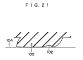
- a portion of the block 100 is worn down in an early stage due to the ununiformity of ground contact pressure, that is, uneven wear is apt to occur. Further, when shear stress caused by local concentration of ground contact pressure is input, only a region in the vicinity of a ground contact end of the block 100 at an input side of shear stress contacts the road surface locally in high pressure, and the tread surface 102 is turned up (see Fig. 21). As a result, the handling stability of tires is adversely affected.
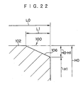
- an improvement in which a region in the vicinity of the ground contact end of the block is chamfered for the purpose of making the ground contact pressure uniform has also been made.
- an end 106 in which the ground contact pressure concentrates be tapered as shown in Fig. 22 or be chamfered substantially in an R-shaped manner as shown in Fig. 23.
- JP-A Japanese Patent Application Laid-Open
- JP-A Japanese Patent Application Laid-Open
- 62-279105 a technique has been proposed in which a convex (chamfered) shape is formed at an upper portion of a block and along a circumferential or transverse direction of a tire.
- a tread surface of the block in which the above-described effect consists with other various characteristics only by using such technique.
- determination of the shape of the tread surface is based on trial and error, and is also attended with difficulties.
- the distribution of ground contact pressure depends on the configuration of a tread pattern and is affected by deformation of the block to which input is applied (for example, deformation from the state of Fig. 19 to that of Fig. 20B, or deformation from the state of Fig. 19 to that of Fig. 21). Therefore, it is difficult to predict the distribution.
- the invention described in claim 1 is a pneumatic tire in which a plurality of blocks demarcated by circumferential grooves extending in a circumferential direction of the tire and grooves intersecting the circumferential grooves, are provided on a tread, wherein at least a portion of a block edge is chamfered from the side of a block center to a groove wall surface of each of the blocks; a heightwise cross sectional form of a chamfer portion perpendicular to the groove wall surface is formed by a combination of a plurality of chamfer forms; and an angle formed by a tangential line of the chamfer portion with respect to a horizontal extension line of the surface of the block center in a heightwise cross section perpendicular to the groove wall surface increases from the side of the block center to the side of the block end.
- the invention described in claim 2 is characterized in that, in the invention described in claim 1, the cross sectional form of the chamfer portion is provided such that the block central side thereof (a portion of the cross sectional form of the chamfer portion on the block central side) is formed as a straight line portion and the block end side thereof (a portion of the cross sectional form of the chamfer portion on the block end side) is formed by at least one curved line portion having a fixed curvature.
- the invention described in claim 3 is characterized in that, in the invention described in claim 1 or claim 2, the cross sectional form of the chamfer portion is comprised of two curved line portions having different curvatures.
- the invention described in claim 4 is characterized in that, in the invention described in any one of claims 1 to 3, when in the heightwise cross section perpendicular to the groove wall surface, a length of the chamfer portion measured along a horizontal extension line of the surface of the block central portion is represented by L1 and a likewise measured length of the block is represented by L0, the ratio L1/L0 is in the range from 0.02 to 0.3.
- the invention described in claim 5 is characterized in that, in the invention described in any one of claims 1 to 4, a distance, measured along a radial direction of the tire, between the horizontal extension line of the surface of the block central portion and an intersection point of the chamfer portion and the groove wall surface is in the range from 0.10 mm to 2.50 mm.
- the invention described in claim 6 is characterized in that, in the invention described in any one of claims 1 to 5, when a heightwise distance between a groove bottom of the block and the intersection point of the chamfer portion and the groove wall surface is represented by H 1 and the maximum height of the block is represented by H0, the ratio H1/H0 is greater than or equal to 0.75 and less than 1.0.
- the invention described in claim 7 is characterized in that, in the invention described in any one of claims 1 to 6, the cross sectional form of the chamfer portion changes at a peripheral edge of the block for each portion of the block.
- the invention described in claim 8 is characterized in that, in the invention described in any one of claims 1 to 7, a peripheral protuberant portion is formed on a tread surface of the block in the vicinity of the end edge thereof in such a manner that the height of the block gradually decreases toward the block end edge and also toward the central portion of the block.
- the invention described in claim 9 is characterized in that, in the invention described in claim 8, the peripheral protuberant portion is formed in at least both end edge portions of the block in the cross section of the block taken along the heightwise direction.
- the invention described in claim 10 is characterized in that, in the invention described in claim 8 or claim 9, the peripheral protuberant portion is disposed in vicinities of the end edges at both sides of the block in the circumferential direction of the tire.
- the invention described in claim 11 is characterized in that, in the invention described in any one of claims 8 to 10, the peripheral protuberant portion is disposed in vicinities of the end edges at both side of the block in the transverse direction of the tire.
- the invention described in claim 12 is characterized in that, in the invention described in any one of claims 8 to 11, a dimension HH 1 measured along a radial direction of the tire, between an intersection point of a groove wall surface of the block and the peripheral protuberant portion, and a height position of a top of the peripheral protuberant portion is in the range from 0.1 to 2.5 mm.
- HH2 measured along the radial direction of the tire, between a maximum depth portion in a central region of the block and the height position of the top of the peripheral protuberant portion is in the range from 0.1 to 2.50 mm.
- the invention described in claim 14 is characterized in that, in the invention described in any one of claims 8 to 13, the ratio between the dimension HH1 measured along a radial direction of the tire, between an intersection point of a groove wall surface of the block and the peripheral protuberant portion, and a height position of a top of the peripheral protuberant portion, and the dimension HH2 measured along the radial direction of the tire, between a maximum depth portion in a central region of the block and the height position of the top of the peripheral protuberant portion, that is, HH2/HH1, is 1.5 or less.
- the invention described in claim 15 is characterized in that, in the invention described in any one of claims 8 to 14, a dimension LL1 measured in a direction of the tread surface, between the intersection point of the groove wall surface of the block and the peripheral protuberant portion, and the top of the peripheral protuberant portion is 10.0 mm or less.
- the invention described in claim 16 is characterized in that, in the invention described in any one of claims 8 to 15, with respect to the dimension LL1 measured in a direction along the tread surface between the intersection point of the groove wall surface of the block and the peripheral protuberant portion and the top of the peripheral protuberant portion, and a dimension LL2 measured in the direction along the tread from the top of the peripheral protuberant portion to the maximum depth portion in the central region of the block, LL1/LL2 is 2.0 or less.
- the invention described in claim 17 is characterized in that, in the invention described in any one of claims 8 to 16, with resect to the dimension HH 1 measured along a radial direction of the tire, between an intersection point of a groove wall surface of the block and the peripheral protuberant portion, and a height position of a top of the peripheral protuberant portion, and the dimension LL1 measured in a direction along the tread surface, between the intersection point of the groove wall surface of the block and the peripheral protuberant portion, and the top of the peripheral protuberant portion, HH1/LL1 is 1.0 or less.
- the invention described in claim 18 is characterized in that, in the invention described in any one of claims 8 to 17, with respect to the dimension HH2 measured along the radial direction of the tire between a maximum depth portion in a central region of the block and the height position of the top of the peripheral protuberant portion, and the dimension LL2 measured in the direction along the tread from the top of the peripheral protuberant portion to the maximum depth portion in the central region of the block, HH2/LL2 is 1.0 or less.
- the invention described in claim 19 is characterized in that, in the invention described in any one of claims 8 to 18, the ratio between the maximum height H0 and the minimum height T1 of the block, that is, T1/H0 is set in the range of 0.75 ⁇ T1/H0 ⁇ 1.0.
- the invention described in claim 20 is characterized in that, in the invention described in any one of claims 8 to 19, the peripheral protuberant portion is formed along an entire periphery of the end edge portion of the block.
- the ground contact pressure distribution of each of blocks formed on a tread gradually increases from a central portion C to ends of the block and becomes high locally at the ends.
- an angle of inclination (including a curvature) of the chamfer portion be preferably made larger toward the end of the block as shown in Fig. 1.
- angle of inclination is an angle formed by an extension line of the surface at the central portion of the block tread surface in a cross sectional form of the block with respect to a tangential line of the chamfer portion.
- a portion of the block in which the ground contact pressure does not change so much (that is, the side of the center of the block) is formed as a straight line (a fixed angle of inclination) portion and a portion of the block in which the ground contact pressure changes greatly (that is, the side of the block end) is formed by at least one curved line portion having a fixed curvature. Therefore, although it is a simple structure, the ground contact pressure can be equalized.
- the side of the center of the block in which the ground contact pressure does not change so much, and the side of the block end in which the ground contact pressure changes greatly, are formed by two curved line portions having different curvatures. Therefore, in spite of a simple structure, equalization of the ground contact pressure can be accomplished.
- the side of the center of the block is formed as a straight line portion, only the side of the block end can be formed by two curved line portions having different curvatures. As a result, the ground contact pressure can be equalized still more.
- L1/L0 is in the range from 0.02 to 0.3.
- H1/H0 When H1/H0 is less than 0.75, the ground contacting area decreases and the handling stability of the tire is deteriorated. On the other hand, when the H1/H0 is 1.0 or more, an effect of equalizing the ground contact pressure by the chamfer portion is small.
- the distribution of ground contact pressure between ends of the block varies depending on the measured direction (i.e., in the circumferential direction of the tire or in the transverse direction of the tire) or depending on the distance from a corner of the block.
- the ground contact pressure on the tread surface is equalized further.
- the ground contact pressure particularly becomes especially large at a ground contacting end of the block and becomes large at the central portion of the block, and relatively becomes small in a region of the block between the ground contacting end and the central portion (see Fig. 20A).
- the peripheral protuberant portion 20 is formed on the tread surface of the block 18 in the vicinity of the end edge of the block in such a manner that the height thereof gradually decreases toward the end edge of the block and toward the central portion of the block, the height of each of regions of the block at both sides of the peripheral protuberant portion 20, that is, the height of the block at the sides of the end edge and the central portion is lower than the peripheral protuberant portion 20. Accordingly, the ground contact pressure at the sides of the end edge and at the central portion of the block can be reduced and ununiformity of the ground contact pressure can be prevented.
- the circumferential grooves may be disposed parallel to the circumferential direction of the tire or may be inclined to the circumferential direction of the tire to a certain extent.
- the lateral (direction) grooves may merely intersect the circumferential (direction) grooves at the least.
- the lateral grooves may be disposed parallel to the transverse direction of the tire or may be inclined with respect to the transverse direction of the tire to a certain extent.
- the peripheral protuberant portion is preferably raised by a gradual slope, that is, a contour line of the tread surface of the block in the cross section along the heightwise direction is preferably formed by a smooth curved line.
- the peripheral protuberant portion is formed in at least both end edge portions of the block in the cross section along the heightwise direction of the block. Therefore, ununiformity of the ground contact pressure in at least the vicinities of both end edges of the block can be suppressed and the ground contact pressure can be made uniform along the cross sectional direction of the block.
- the peripheral protuberant portion is disposed at both sides of the block in the circumferential direction of the tire, and therefore, ununiformity of the ground contact pressure of the block in the circumferential direction of the tire can be suppressed.
- an extremely local deformation of the block caused by braking/driving force is prevented and the handling stability improves.
- uneven wear in the vicinity of the block end in the circumferential direction of the tire, which is caused by ununiformity of the ground contact pressure of the block in the circumferential direction of the tire, can be prevented.
- peripheral protuberant portion is formed at both sides of the block in the circumferential direction of the tire, directionality of the tire is not caused.
- the peripheral protuberant portion is formed on the tread surface of the block in the vicinities of the end edges of the block in the transverse direction of the tire in such a manner that the height thereof gradually decreases from the top of the peripheral protuberant portion, which is disposed toward the center of the block from the end edge of the block in the transverse direction of the tire, to the central portion of the block in the transverse direction of the tire and to the end edges of the block in the transverse direction of the tire, the ground contact pressure at ground contacting ends of the block in the transverse direction of the tire can be reduced and ununiformity of the ground contact pressure of the block in the transverse direction of the tire can be suppressed.
- the upper limit of the dimension HH 1 is set to be 2.5 mm so as to prevent an extreme decreasing the ground contacting area.
- the dimension HH 1 is in the range from 0.1 to 2.5 mm.
- the dimension HH 1 is more preferably in the range from 0.3 to 1.0 mm.
- the ground contact pressure at the central portion of the block can reliably be reduced.
- An optimum value of the dimension HH2 is determined for each portion of the block depending on the compressive rigidity and shape of the block.
- the effect of the invention is produced when the dimension HH2 is greater than 0. That is, so long as the dimension HH2 is a positive value, an aim at improvement is achieved.
- the range of the dimension in which an excellent effect is produced and the performances are maintained is 0.1 to 2.5 mm.
- the ground contact pressure can be equalized still more.
- the dimension LL1 is set outside the above-described range, there is a possibility that the ground contact pressure may be made ununiform.
- the dimension LL1 is preferably in the range from 1.5 to 6.0 mm, more preferably in the range from 1.5 to 4.0 mm.
- the dimension LL2 is determined depending on the dimension LL1.
- the dimension LL2 is made larger than the dimension LL1.
- partial inversion of ground contact pressure may be caused depending on the cross sectional form.
- LL1/LL2 is 2.0 or less. Therefore, an excellent effect can be expected.
- T1/H0 is less than 0.75, a region of the block having the minimum height T1, that is, a low region of the block does not contact the road surface and there is a possibility that the ground contacting area of the block may decrease.
- T1/H0 is 1, an effect of reducing the ground contact pressure is not obtained. Accordingly, in order to maintain the ground contacting area of the block and to reliably obtain the effect of reducing the ground contact pressure, T1/H0 is preferably set such that 0.75 ⁇ T1/H0 ⁇ 1.0.
- the peripheral protuberant portion is formed along the entire periphery of the end edge of the block, and therefore, ununiformity of the ground contact pressure can be suppressed over the entire periphery of the end edge of the block and the vicinity thereof irrespective of the shape of the block.
- a pneumatic tire 10 includes a cylinder-shaped tread 12 extending between a pair of side walls (not shown) disposed parallel to each other.
- the tread 12 comprises a plurality of main grooves 14 formed along a circumferential direction of the tire (that is, the direction indicated by arrow P), and a plurality of lug grooves 16 formed along a transverse direction of the tire (that is, the direction indicated by arrow W).
- a plurality of blocks 18 are demarcated by the main grooves 14 and the lug grooves 16.
- These blocks 18 are each formed substantially into a rectangular parallelepiped in which a tread surface 20 is a square whose lengths in transverse and circumferential directions of the tire are equal to each other.
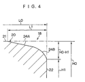
- An end on the tread surface 20 of the block 18 is chamfered (a portion subjected to chamfering is hereinafter referred to as a chamfer portion 24).
- FIG. 1 A cross sectional form (of only the end of the block 18 and the vicinity thereof) of the block 18 in a direction oriented from a groove wall surface 22 tangent to the chamfer portion 24 of the block 18 toward a side wall opposite to the groove wall surface 22 so as to be substantially perpendicular to the groove wall surface 22, is shown in Fig. 1.
- the cross sectional form of the chamfer portion 24 is formed in such a manner that a curvature of the chamfer portion 24 gradually increases from a central side of the block 18 to the groove wall surface 22 in the vicinity of the end of the block 18 (that is, an angle of inclination ⁇ is made larger). Particularly, the curvature of the chamfer portion 24 is remarkably increased in the vicinity of the groove wall surface 22.
- a portion at the center of the tread surface 20 in the block 18, which is not chamfered, is hereinafter referred to as a central portion 21.
- the chamfer portion 24 is formed such that the curvature thereof gradually increases toward the vicinity of the groove wall surface (see Fig. 20A) in which the ground contact pressure remarkably increases. Therefore, an amount by which the ground contact pressure is suppressed increases toward the vicinity of the groove wall surface 22 at which the ground contact pressure becomes maximum, and the ground contact pressure on the tread surface 20 is equalized.
- the methods (2) and (3) be used from the standpoint of equalization of ground contact pressure in the end of the block and the vicinity thereof.
- Tires used for the test were radial tires whose size was 205/55R16. As illustrated in Fig. 2, a tread pattern of each tire is a combination of squares. The block size was 30 mm ⁇ 30 mm and the height of the block was 10 mm.
- a feeling evaluation was conducted with a vehicle to which the above-described tires were mounted and which was run by an experienced driver on a test course road.
- the evaluation was made as an index with the result of the tire of the conventional example 1 being 100. The higher the index, the better the feeling evaluation.
- L0 indicates a transverse dimension of the block along the cross sectional direction
- L1 indicates a transverse dimension of the block along the cross sectional direction from the groove wall surface 22 to a boundary between the chamfer portion 24 and the central portion 21.
- H0 indicates the maximum height of the block and H 1 indicates a height at an intersection point of the chamfer portion 24 and the groove wall surface 22.
- the "height” mentioned herein means a dimension measured from the bottom of the main groove 14.
- Chamfer form Block-center side Chamfer form in a peripheral portion of block L1/L0 H1/H0 H1 Score Of Evaluation Example 1 Straight line (0.5 mm chamfered in 4mm) R4.0 0.2 0.85 1.5 115
- Example 2 R16.25 R4.0 0.2 0.85 1.5 122 Conventional Example 1 ----- ----- ----- ----- ----- 100 Conventional Example 2 Straight line (1.5mm chamfered in 6mm) ⁇ 0.2 0.85 1.5 108
- Conventional Example 3 R12.75 ⁇ 0.2 0.85 1.5 109
- Example 2 In order to ascertain the difference in the effect based on the length L1 in the cross sectional direction to be chamfered in the case of "R1+R2" in which the most excellent effect was obtained (Example 2), Examples 1-1 to 1-5 and Conventional example 1-1 (no chamfer formed) were compared. The same testing method and evaluation method are used. The test results are shown in Table 2. L1/L0 Score of evaluation Example 1-1 0.01 106 Example 1-2 0.02 112 Example 1-3 0.15 122 Example 1-4 0.29 114 Example 1-5 0.31 107 Conventional Example 1-1 ----- 100
- Example 2-1 to 2-5 and Conventional Example 2-1 were compared. The same testing method and evaluation method are used. The test results are shown in Table 3. H0-H1 H1/H0 Score of evaluation Example 1-1 0.05 0.995 102 Example 1-2 0.10 0.990 112 Example 1-3 1.25 0.875 122 Example 1-4 2.5 0.750 112 Example 1-5 2.6 0.740 109 Example 1-6 3.0 0.700 103 Example 1-7 3.2 0.680 97 Conventional Example 1 ----- ----- 100
- a preferred chamfer dimension is determined based on the above-described standard.
- the block size varies for each block pattern. It is preferable from Table 2 that a chamfer length L1 be 0.02 to 0.3 with the cross sectional length L0 of the block (along the transverse direction of the tire) being 1.
- the height of chamfer (H0-H1) be 0.1 to 2.5 mm. Furthermore, a desired effect can be recognized when the height position of the intersection point of the chamfer portion 24 and the groove wall surface 22 is approximately 0.7 or greater with respect to the height of the block being 1.
- the height position of the intersection point is more preferably 0.750 to 0.990.
- Fig. 6 shows a cross section of the block 18 taken along the circumferential direction of a tire and Fig. 7 shows a cross section of the block 18 taken along the transverse direction of the tire.
- a peripheral protuberant portion 26 is formed on a tread surface of the block 18 in the vicinities of end edges of the block 18 both in circumferential and transverse directions of the tire.
- the peripheral protuberant portion 26 is continuously formed along the outer periphery of the block 18.
- a contour line of the peripheral protuberant portion 26 is preferably formed by a smooth curved line as shown in the above-described cross sectional views.
- a top 26A is positioned further at the inner side of the block than an extension line of a side surface (groove wall) 18A of the block 18 and the height of the block 18 gradually decreases from the top 26A toward the end edge of the block 18 and also toward the central portion of the block 18.
- the ground contact pressure becomes especially large at a ground-contact end of the block and also becomes large at the central portion of the block, and becomes relatively small in a region between the ground-contact end and the central portion of the block.
- the peripheral protuberant portion 26 is formed on the tread surface of the block 18 in the vicinity of the end edge of the block in such a manner that the height of the block gradually decreases toward the end edge of the block and also toward the central portion of the block, the ground contact pressure at the end edge of the block and at the central portion of the block can be reduced when the block contacts the road surface (the states indicated by the phantom lines in Figs. 6 and 7).
- the ground contact pressure can be equalized both in the circumferential and axial directions of the tire.
- ununiformity of the ground contact pressure in the circumferential direction of the tire can be prevented due to the peripheral protuberant portion 26 being formed at both sides of the block 18 in the circumferential direction of the tire. Therefore, occurrence of a buckling phenomenon caused by braking/driving force can be prevented and handling stability can be improved. Further, uneven wear in the vicinities of circumferential direction ends of the tire, caused by uniformity of the ground contact pressure in the circumferential direction of the tire, can be suppressed.
- peripheral protuberant portion 26 is also provided at both lateral ends of the tire, generation of uneven wear in the vicinities of lateral ends of the tire, caused by ununiformity of the ground contact pressure in the transverse direction of the tire, can be suppressed.
- the dimension HH1 is set in the range from 0.1 to 2.5 mm, ununiformity of the ground contact pressure can be prevented without reducing a ground-contacting area at the end edge of the block.
- the ground contact pressure at the central portion of the block can reliably be reduced without reducing a ground-contacting area at the central portion of the block.
- the ratio HH2/HH1 is set to be 1.5 or less, the ground contact pressure in the vicinity of the maximum depth portion of the block (at the central portion of the block) and the ground contact pressure of the top 26A of the peripheral protuberant portion 26 approximate to each other when the block 18 contacts the road surface. Therefore, the above-described numerical range is preferable.
- the dimension LL1 is 10.0 mm or less so as to allow further equalization of the ground contact pressure.
- LL1/LL2 is 2.0 or less so as to equalize the distribution of ground contact pressure of the rectangular block 18.
- HH1/LL1 is 1.0 or less so as to realize a uniform state of the ground contact pressure.
- HH2/LL2 is 1.0 or less so as to enhance the effect of equalization of the ground contact pressure distribution.
- the ratio between the maximum height H0 of the block 18 and the minimum height T1 of the block 18 (T1/H0) is set such that 0.75 ⁇ T1/H0 ⁇ 1.0, the ground contact area is maintained and the effect of reducing the ground contact pressure can reliably be obtained. Therefore, the above-described range is preferable.
- test results are evaluation results of handling stability obtained by using an actual vehicle, and are each expressed as an index with the tire having the conventional block with no chamfer being 100. The higher the index, the better the performance. Further, the above-described evaluation was conducted assuming the desired standard being 110 or greater, which greatly differs from the conventional example.
- Fig. 12 shows the evaluation results when the dimension HH 1 measured from the intersection point C of the side surface 18A of the block 18 and the peripheral protuberant portion 26 to the height position of the top 26A of the peripheral protuberant portion 26 along the radial direction of the tire is changed at different values.
- the proper value of the dimension HH 1 is 0.1 to 2.5 mm, more preferably 0.5 to 1.2 mm. Further, when compared with the block in which only chamfer is provided, it can be seen that change in chamfering on the periphery of the block produces still more excellent effect.
- Fig. 13 shows the evaluation results when the dimension H2 measured from the maximum depth portion 18B at the central region of the block 18 to the height position of the top 26A of the peripheral protuberant portion 26 along the radial direction of the tire is changed at different values.
- the proper value in this case be desirably set at similar values to those of a corner portion in the cross section of the block.
- Fig. 14 shows the evaluation results when the ratio HH2/HH1 is changed at different values.
- the ratio HH2/HH1 is approximately 1.5 or less.
- the HH2/HH1 is more desirably in the range of 0.15 to 1.0.
- Fig. 15 shows the evaluation results when the dimension LL1 measured from the intersection point C to the height position of the top 26A in the direction along the tread surface of the block 18 is changed at different values.
- the dimension LL2 which is a distance from the top 26A to the maximum depth portion 18B in the direction along the tread surface of the block 18 is given by subtracting the dimension LL1 from a half of the block length of the cross section in the transverse direction thereof (with the maximum depth portion 18B positioned at the central region of the block). It can be seen from the result that an excellent effect is exhibited when the dimension LL1 is 10 mm or less. Further, it can also be seen that the ratio LL1/LL2 in this case be 2.0 or less. In order to obtain the most excellent effect, the dimension LL1 is set in the range from 1 to 6 mm. It can be seen that in this case the ratio LL1/LL2 is approximately in the range from 0.1 to 0.7. That is, the above-described numerical ranges indicates that the dimension LL1 at the side near the end of the block in the cross section is preferably shorter.
- Fig. 16 shows the evaluation results when the ratio HH1/LL1 is changed at different values.
- Fig. 17 shows the evaluation results when the relationship between HH2 and LL2 is changed in various manners.
- the evaluation result obtained by using an actual vehicle indicates that further improvement in the performance can be expected by changing chamfering on the circumference of the block.
- the reason is, as is considered, that a proper distribution of chamfering exists with respect to the ground-contacting characteristics influenced by the shape of the block itself.
- the circumferential groove 14 extends along the circumferential direction of the tire (i.e., the direction indicated by arrow A) and the lateral groove 16 extends along the transverse direction of the tire (i.e., the direction indicated by arrow B).
- the circumferential groove 14 may be inclined with respect to the circumferential direction of the tire and the lateral groove 16 may be inclined with respect to the transverse direction of the tire.
- the block 18 of the above-described embodiment is rectangular, but the present invention is not limited to the same.
- the shape of the block 18 when the tread 12 is seen from above may be a polygon such as a diamond shape, a hexagon, or an octagon depending on orientation of the circumferential groove 14 and the lateral groove 16, or provision of chamfering, notching, or the like.
- the block 18 may have a substantially U-shaped configuration or may also have a circular or ellipsoidal configuration.
- the peripheral protuberant portion 26 (in this drawing, a region indicated by hatched lines) is formed along the end edge of the block. As shown in the cross sectional view of Fig. 18B, the peripheral protuberant portion 26 is provided at three locations in the cross section, that is, at both end edges of the block and at the central portion thereof, depending on a position at which the block 18 is cut.
- the tire size of each tire was 195/50R15 (having a tread pattern shown in Fig. 25) and a test using an actual vehicle was conducted with the tires filled with an internal pressure of 2.0 kg/cm 2 .
- the block size was 30 mm (in the circumferential direction of the tire) ⁇ 20 mm (in the transverse direction of the tire) ⁇ 9 mm (in the height of the tire).
- the input 1 is applied under a vertical load condition (corresponding to bearing stress of 4 kgf/cm 2 ).
- the input 2 to 8 are shearing force input in directions shown in Fig. 9 (evaluation with an amount of shear deformation of 1 mm).
- the worn state of the block of Example 4 is shown in Fig. 11 and the worn state of the block in the conventional tire is shown in Fig. 10.
- the solid line indicates a cross section in the vicinity of the ground-contacting end of the block before wear
- the phantom line indicates a cross section in the vicinity of the ground-contacting end of the block after wear.
Landscapes
- Engineering & Computer Science (AREA)
- Mechanical Engineering (AREA)
- Tires In General (AREA)
Abstract
Description
| Chamfer form Block-center side | Chamfer form in a peripheral portion of block | L1/L0 | H1/H0 | H1 | Score Of Evaluation | |
| Example 1 | Straight line (0.5 mm chamfered in 4mm) | R4.0 | 0.2 | 0.85 | 1.5 | 115 |
| Example 2 | R16.25 | R4.0 | 0.2 | 0.85 | 1.5 | 122 |
| Conventional Example 1 | ----- | ----- | ----- | ----- | ----- | 100 |
| Conventional Example 2 | Straight line (1.5mm chamfered in 6mm) | ← | 0.2 | 0.85 | 1.5 | 108 |
| Conventional Example 3 | R12.75 | ← | 0.2 | 0.85 | 1.5 | 109 |
| L1/L0 | Score of evaluation | |
| Example 1-1 | 0.01 | 106 |
| Example 1-2 | 0.02 | 112 |
| Example 1-3 | 0.15 | 122 |
| Example 1-4 | 0.29 | 114 |
| Example 1-5 | 0.31 | 107 |
| Conventional Example 1-1 | ----- | 100 |
| H1/H0 | H1 |
| 0.85 | 1.5 |
| H0-H1 | H1/H0 | Score of evaluation | |
| Example 1-1 | 0.05 | 0.995 | 102 |
| Example 1-2 | 0.10 | 0.990 | 112 |
| Example 1-3 | 1.25 | 0.875 | 122 |
| Example 1-4 | 2.5 | 0.750 | 112 |
| Example 1-5 | 2.6 | 0.740 | 109 |
| Example 1-6 | 3.0 | 0.700 | 103 |
| Example 1-7 | 3.2 | 0.680 | 97 |
| Conventional Example 1 | ----- | ----- | 100 |
| Results obtained by using an actual vehicle | |||||||
| LL1(mm) Maximum value | HH1(mm) Maximum value | LL2(mm) Maximum value | HH2(mm) maximum value | T1/H0 | Performance | ||
| Handling stability | Riding comfort | ||||||
| Conventional Example | ----- | ----- | ----- | ----- | 1.0 | 100 | 100 |
| Example 1 | 1.0 | 0.3 | 17.0 | 0.2 | 0.97 | 112 | 100 |
| Example 2 | 1.5 | 0.3 | 16.5 | 0.4 | 0.96 | 114 | 100 |
| Example 3 Example 4 | 3.0 | 0.4 | 15.0 | 0.3 | 0.96 | 115 | 100 |
| 4.0 | 0.8 | 14.0 | 0.6 | 0.91 | 121 | 98 | |
| Example 5 Example 6 | 5.0 | 0.9 | 13.0 | 0.6 | 0.90 | 118 | 99 |
| 6.0 | 1.0 | 12.0 | 1.0 | 0.88 | 116 | 99 | |
| Example 7 | 8.0 | 1.5 | 10.0 | 1.0 | 0.83 | 112 | 98 |
| Example 8 | 10.0 | 2.5 | 8.0 | 2.0 | 0.72 | 108 | 98 |
| Comparison of standard deviation of ground contact pressure between the conventional tire and the tire of Example 4 | ||
| Conventional tire | Tire of Example 4 | |
| | 100 | 66 |
| | 100 | 55 |
| | 100 | 54 |
| | 100 | 51 |
| Input 5 | 100 | 54 |
| | 100 | 55 |
| Input 7 | 100 | 54 |
| | 100 | 51 |
| | 100 | 54 |
| Average of | 100 | 55 |
| Comparison of ground-contacting area between the conventional tire and the tire of Example 4 | ||
| Conventional tire | Tire of Example 4 | |
| | 100 | 101 |
| | 100 | 101 |
| | 100 | 100 |
| | 100 | 100 |
| Input 5 | 100 | 100 |
| | 100 | 101 |
| Input 7 | 100 | 100 |
| | 100 | 100 |
| | 100 | 100 |
| Average of | 100 | 100 |
Claims (15)
- A pneumatic tire (10) in which a plurality of blocks (18) demarcated by circumferential grooves (14) extending in a circumferential direction of the tire and grooves (16) intersecting the circumferential grooves, are provided on a tread (12),
characterized in that a peripheral protuberant portion (26) is formed on a tread surface (20) of the block (18) in the vicinity of the end edge thereof in such a manner that the height of the block gradually decreases toward the block end edge (24B) and also toward the central portion (21) of the block. - A pneumatic tire as claimed in claim 1, characterized in that the peripheral protuberant portion (26) is formed in at least both end edges of the block (18) in the cross section of the block taken along the heightwise direction.
- A pneumatic tire as claimed in claim 1 or claim 2, characterized in that the peripheral protuberant portion (26) is disposed in vicinities of the end edges at both sides of the block (18) in the circumferential direction of the tire.
- A pneumatic tire as claimed in any of claims 1 to 3, characterized in that the peripheral protuberant portion (26) is disposed in vicinities of the end edges at both sides of the block (18) in the transverse direction of the tire.
- A pneumatic tire as claimed in any of claims 1 to 4, characterized in that a dimension HH 1 measured along a radial direction of the tire, between an intersection point of a groove wall surface (22) of the block (18) and the peripheral protuberant portion (26), and a height position of a top (26A) of the peripheral protuberant portion is in the range from 0.1 to 2.5 mm.
- A pneumatic tire as claimed in any of claims 1 to 5, characterized in that a dimension HH2 measured along the radial direction of the tire, between a maximum depth portion (18B) in a central region (21) of the block (18) and the height position of the top (26A) of the peripheral protuberant portion (26) is in the range from 0.1 to 2.50 mm.
- A pneumatic tire as claimed in any of claims 1 to 6, characterized in that the ratio between the dimension HH1 measured along a radial direction of the tire, between an intersection point of a groove wall surface (12) of the block (18) and the peripheral protuberant portion (26), and a height position of a top (26A) of the peripheral protuberant portion, and the dimension HH2 measured along the radial direction of the tire, between a maximum depth portion (18B) in a central region (21) of the block and the height position of the top (26A) of the peripheral protuberant portion (26), that is HH2/HH1, is 1.5 or less.
- A pneumatic tire as claimed in any of claims 1 to 7, characterized in that a dimension LL1 measured in a direction of the tread surface (20), between the intersection point of the groove wall surface (22) of the block (18) and the peripheral protuberant portion (26), and the top (26A) of the peripheral protuberant portion is 10.0 mm or less.
- A pneumatic tire as claimed in any of claims 1 to 8, characterized in that the ratio between the dimension LL1 measured in a direction along thetread surface (20), between the intersection point of the groove wall surface (22) of the block (18) and the peripheral protuberant portion (26), and the top (26A) of the peripheral protuberant portion, and a dimension LL2 measured in the direction along the tread (12) from the top (26A) of the peripheral protuberant portion (26) to the maximum depth portion (18B) in the central region (21) of the block (18), that is LL1/LL2, is 2.0 or less.
- A pneumatic tire as claimed in any of claims 1 to 9, characterized in that the ratio between the dimension HH1 measured along a radial direction of the tire, between an intersection point of a groove wall surface (22) of the block (18) and the peripheral protuberant portion (26), and a height position of a top (26A) of the peripheral protuberant portion, and the dimension LL 1 measured in a direction along the tread surface (20), between the intersection point of the groove wall surface (22) of the block (18) and the peripheral protuberant portion (26), and the top (26A) of the peripheral protuberant portion, that is HH1/LL1, is 1.0 or less.
- A pneumatic tire as claimed in any of claims 1 to 10, characterized in that the ratio between the dimension HH2 measured along the radial direction of the tire, between a maximum depth portion (18B) in a central region (21) of the block (18) and the height position of the top (26A) of the peripheral protuberant portion (26), and the dimension LL2 measured in the direction along the tread (12) from the top (26A) of the peripheral protuberant portion (26) to the maximum depth portion (18B) in the central region (21) of the block (18), that is HH2/LL2, is 1.0 or less.
- A pneumatic tire as claimed in any of claims 1 to 11, characterized in that the ratio between the maximum height H0 and the minimum height T1 of the block, that is T1/H0, is set in the range of 0.75 ≤ T1/H0 < 1.0.
- A pneumatic tire as claimed in any of claims 1 to 12, characterized in that the peripheral protuberant portion (26) is formed along an entire periphery of the end edge of the block (18).
- A pneumatic tire as claimed in any of claims 1 to 13, characterized in that at least a portion of a block edge is chamfered from the side of a block center (2 1 ) to a groove wall surface (22) of each of the blocks (18); and
an angle () formed by a tangential line of the chamfer portion (24) with respect to a horizontal extension line of the surface of the block center (21) in a heightwise cross section perpendicular to the groove wall surface (22) increases from the side of the block center (24A) to the side of the block end (24B). - A pneumatic tire as claimed in claim 14, characterized in that said angle (0) increases smoothly toward the side of the block end (24B).
Applications Claiming Priority (3)
| Application Number | Priority Date | Filing Date | Title |
|---|---|---|---|
| JP4320899 | 1999-02-22 | ||
| JP4320899 | 1999-02-22 | ||
| EP00904086A EP1074405B1 (en) | 1999-02-22 | 2000-02-22 | Pneumatic tire |
Related Parent Applications (1)
| Application Number | Title | Priority Date | Filing Date |
|---|---|---|---|
| EP00904086A Division EP1074405B1 (en) | 1999-02-22 | 2000-02-22 | Pneumatic tire |
Publications (3)
| Publication Number | Publication Date |
|---|---|
| EP1484197A2 true EP1484197A2 (en) | 2004-12-08 |
| EP1484197A3 EP1484197A3 (en) | 2005-04-13 |
| EP1484197B1 EP1484197B1 (en) | 2015-12-30 |
Family
ID=12657514
Family Applications (2)
| Application Number | Title | Priority Date | Filing Date |
|---|---|---|---|
| EP04021188.0A Expired - Lifetime EP1484197B1 (en) | 1999-02-22 | 2000-02-22 | Pneumatic tire |
| EP00904086A Expired - Lifetime EP1074405B1 (en) | 1999-02-22 | 2000-02-22 | Pneumatic tire |
Family Applications After (1)
| Application Number | Title | Priority Date | Filing Date |
|---|---|---|---|
| EP00904086A Expired - Lifetime EP1074405B1 (en) | 1999-02-22 | 2000-02-22 | Pneumatic tire |
Country Status (6)
| Country | Link |
|---|---|
| US (2) | US6910512B1 (en) |
| EP (2) | EP1484197B1 (en) |
| JP (1) | JP4608103B2 (en) |
| DE (1) | DE60025587T2 (en) |
| ES (1) | ES2255974T3 (en) |
| WO (1) | WO2000050252A1 (en) |
Families Citing this family (28)
| Publication number | Priority date | Publication date | Assignee | Title |
|---|---|---|---|---|
| ATE281317T1 (en) * | 2000-07-24 | 2004-11-15 | Michelin Soc Tech | TREAD PROFILE FOR A VEHICLE Pneumatic TIRE |
| JP2002219907A (en) * | 2001-01-25 | 2002-08-06 | Bridgestone Corp | Tire for working vehicle |
| FR2828134A1 (en) * | 2001-08-06 | 2003-02-07 | Michelin Soc Tech | Pneumatic tire tread has blocks formed by lengthwise and transverse grooves and having surfaces of predetermined shape |
| DE60331744D1 (en) * | 2002-09-10 | 2010-04-29 | Yokohama Rubber Co Ltd | TIRE |
| US6983777B2 (en) | 2002-10-15 | 2006-01-10 | The Goodyear Tire & Rubber Company | Tire tread with multi-planar chamfers |
| JP4295498B2 (en) * | 2002-12-13 | 2009-07-15 | 住友ゴム工業株式会社 | Radial tire for ATV |
| JP4461746B2 (en) * | 2003-09-10 | 2010-05-12 | 横浜ゴム株式会社 | Pneumatic tire |
| JP4586486B2 (en) * | 2004-10-18 | 2010-11-24 | 横浜ゴム株式会社 | Pneumatic tire |
| JP4648113B2 (en) * | 2005-07-04 | 2011-03-09 | 株式会社ブリヂストン | Pneumatic tire |
| US20070039672A1 (en) * | 2005-08-16 | 2007-02-22 | Lo Tsai J | Tire with protection protrusions encompassing discharge terminals |
| EP1918130A4 (en) * | 2005-08-23 | 2009-06-10 | Bridgestone Corp | Pneumatic tire |
| DE102006030390A1 (en) * | 2006-07-01 | 2008-01-03 | Continental Aktiengesellschaft | Vehicle tires with a profiled tread |
| JP2009023601A (en) * | 2007-07-23 | 2009-02-05 | Sumitomo Rubber Ind Ltd | Pneumatic tire |
| JP5155049B2 (en) * | 2008-07-16 | 2013-02-27 | 株式会社ブリヂストン | Pneumatic tires for motorcycles |
| CN102666135B (en) * | 2009-11-23 | 2015-12-16 | 米其林集团总公司 | There is the tire of the side groove with the chamfering for improving snowfield performance |
| JP5707923B2 (en) * | 2010-12-17 | 2015-04-30 | 横浜ゴム株式会社 | Pneumatic tire |
| FR2983780B1 (en) | 2011-12-08 | 2014-01-10 | Michelin Soc Tech | VARIABLE CHANNEL ROLLER BEARING |
| CN104884276A (en) * | 2012-12-19 | 2015-09-02 | 普利司通美国轮胎运营有限责任公司 | Tire with rounded tread elements |
| EP2977230B1 (en) * | 2013-03-18 | 2017-05-03 | Bridgestone Corporation | Tire |
| JP6211354B2 (en) | 2013-09-04 | 2017-10-11 | 株式会社ブリヂストン | Pneumatic tire |
| DE102014220147A1 (en) * | 2014-10-06 | 2016-06-02 | Continental Reifen Deutschland Gmbh | Vehicle tires |
| EP3274190B1 (en) * | 2015-03-23 | 2021-05-05 | Cooper Tire & Rubber Company | Dual dome convex tire tread block or tread rib |
| JP6710097B2 (en) * | 2016-04-28 | 2020-06-17 | 株式会社ブリヂストン | tire |
| JP6902335B2 (en) * | 2016-06-13 | 2021-07-14 | 株式会社ブリヂストン | tire |
| CN110740882B (en) * | 2017-06-12 | 2022-05-24 | 倍耐力轮胎股份公司 | Tyre for vehicle wheels |
| JP7110699B2 (en) * | 2018-04-18 | 2022-08-02 | 住友ゴム工業株式会社 | tire |
| US11472232B2 (en) | 2019-12-18 | 2022-10-18 | The Goodyear Tire & Rubber Company | Tire with tread elements including dual angled chamfer |
| JP7497607B2 (en) * | 2020-04-30 | 2024-06-11 | 住友ゴム工業株式会社 | tire |
Family Cites Families (27)
| Publication number | Priority date | Publication date | Assignee | Title |
|---|---|---|---|---|
| US1128387A (en) * | 1915-02-16 | Thomas R Tiefenbacher | Tire-tread. | |
| US1210933A (en) * | 1916-05-26 | 1917-01-02 | Bertram C Hamm | Tread for resilient tires. |
| JPS52140102A (en) * | 1976-05-19 | 1977-11-22 | Bridgestone Corp | Pneumatic tyre with less partial wear |
| JPS62161002U (en) * | 1986-04-01 | 1987-10-13 | ||
| JPS62241709A (en) * | 1986-04-14 | 1987-10-22 | Bridgestone Corp | Pneumatic radial tire for heavy load |
| US4722378A (en) * | 1986-05-19 | 1988-02-02 | The Goodyear Tire & Rubber Company | Tire treads with convex elements |
| DE3709427A1 (en) * | 1987-03-21 | 1988-09-29 | Uniroyal Englebert Gmbh | Pneumatic vehicle tyre |
| EP0547039A3 (en) * | 1988-11-30 | 1993-08-11 | Sumitomo Rubber Industries Limited | Pneumatic radial tyre |
| JPH02179508A (en) * | 1988-12-29 | 1990-07-12 | Yokohama Rubber Co Ltd:The | Pneumatic tire |
| JP2800944B2 (en) * | 1989-10-12 | 1998-09-21 | 住友ゴム工業 株式会社 | Pneumatic tire |
| EP0422902B1 (en) * | 1989-10-12 | 1995-09-06 | Bridgestone Corporation | Pneumatic radial tires |
| JP3001220B2 (en) * | 1990-02-23 | 2000-01-24 | 株式会社ブリヂストン | Pneumatic tire |
| US5435364A (en) * | 1990-12-28 | 1995-07-25 | Sumitomo Rubber Industries, Ltd. | Pneumatic radial tire with four main grooves |
| DE69206473T2 (en) * | 1991-05-09 | 1996-07-04 | Bridgestone Corp | Tire. |
| WO1993021028A1 (en) * | 1992-02-28 | 1993-10-28 | Vadim Mikhailovich Matsepuro | Tyre protector |
| JP3229373B2 (en) * | 1992-07-09 | 2001-11-19 | 横浜ゴム株式会社 | Pneumatic tire |
| JPH06166304A (en) * | 1992-09-22 | 1994-06-14 | Bridgestone Corp | Pneumatic tire |
| JP3421114B2 (en) * | 1993-11-22 | 2003-06-30 | 株式会社ブリヂストン | Pneumatic tire |
| JPH07186623A (en) * | 1993-12-27 | 1995-07-25 | Yokohama Rubber Co Ltd:The | Pneumatic tire |
| JP3442839B2 (en) | 1993-12-28 | 2003-09-02 | 株式会社ブリヂストン | Pneumatic tire |
| JP2779765B2 (en) * | 1994-03-18 | 1998-07-23 | 有限会社新津 | Pneumatic tires and vulcanizing molds for manufacturing them |
| JPH08332810A (en) * | 1995-06-07 | 1996-12-17 | Ohtsu Tire & Rubber Co Ltd :The | Pneumatic tire |
| JP3645322B2 (en) * | 1995-08-25 | 2005-05-11 | 株式会社ブリヂストン | Pneumatic tire |
| JP3158061B2 (en) * | 1996-12-19 | 2001-04-23 | 住友ゴム工業株式会社 | Radial tires for heavy loads |
| JP3771351B2 (en) * | 1997-05-02 | 2006-04-26 | 株式会社ブリヂストン | Pneumatic tire |
| GB9814102D0 (en) * | 1998-06-30 | 1998-08-26 | Sumitomo Rubber Ind | Improvements to tyres |
| ATE281317T1 (en) * | 2000-07-24 | 2004-11-15 | Michelin Soc Tech | TREAD PROFILE FOR A VEHICLE Pneumatic TIRE |
-
2000
- 2000-02-22 DE DE60025587T patent/DE60025587T2/en not_active Expired - Lifetime
- 2000-02-22 WO PCT/JP2000/000994 patent/WO2000050252A1/en not_active Ceased
- 2000-02-22 ES ES00904086T patent/ES2255974T3/en not_active Expired - Lifetime
- 2000-02-22 EP EP04021188.0A patent/EP1484197B1/en not_active Expired - Lifetime
- 2000-02-22 JP JP2000600849A patent/JP4608103B2/en not_active Expired - Lifetime
- 2000-02-22 EP EP00904086A patent/EP1074405B1/en not_active Expired - Lifetime
- 2000-02-22 US US09/673,738 patent/US6910512B1/en not_active Expired - Lifetime
-
2005
- 2005-04-04 US US11/097,242 patent/US20050167021A1/en not_active Abandoned
Also Published As
| Publication number | Publication date |
|---|---|
| EP1484197A3 (en) | 2005-04-13 |
| JP4608103B2 (en) | 2011-01-05 |
| EP1074405A1 (en) | 2001-02-07 |
| US6910512B1 (en) | 2005-06-28 |
| ES2255974T3 (en) | 2006-07-16 |
| DE60025587T2 (en) | 2006-07-13 |
| EP1484197B1 (en) | 2015-12-30 |
| DE60025587D1 (en) | 2006-04-06 |
| WO2000050252A1 (en) | 2000-08-31 |
| EP1074405A4 (en) | 2002-02-06 |
| EP1074405B1 (en) | 2006-01-18 |
| US20050167021A1 (en) | 2005-08-04 |
Similar Documents
| Publication | Publication Date | Title |
|---|---|---|
| US6910512B1 (en) | Pneumatic tire having peripheral protuberant portion on each block | |
| JPWO2000050252A1 (en) | pneumatic tires | |
| EP2179868B1 (en) | Pneumatic tire | |
| EP2620299B1 (en) | Pneumatic tire | |
| JP5088319B2 (en) | Pneumatic tire | |
| JP4295728B2 (en) | Pneumatic tire | |
| US8887778B2 (en) | Motorcycle tire for off-road traveling | |
| EP2127907B1 (en) | Pneumatic tire | |
| JP4145300B2 (en) | Pneumatic tire | |
| JP2007182097A (en) | Heavy duty tire | |
| EP4265441B1 (en) | PNEUMATIC | |
| EP0710577B1 (en) | Pneumatic radial tire | |
| US20190375245A1 (en) | Pneumatic tire | |
| JPH03246104A (en) | Pneumatic tire | |
| US6206064B1 (en) | Pneumatic tire having directional tread pattern | |
| JP4102151B2 (en) | Pneumatic tire | |
| JPH11291714A (en) | Pneumatic tire | |
| CN113905902B (en) | Pneumatic tire | |
| JPH06166302A (en) | Radial tires for heavy loads | |
| JP2002274125A (en) | Pneumatic tire | |
| JP4141017B2 (en) | Pneumatic tire | |
| EP4265442A1 (en) | Pneumatic tire | |
| JP4285617B2 (en) | Pneumatic radial tire | |
| JP5141400B2 (en) | Pneumatic tire | |
| US20250296391A1 (en) | Pneumatic tire |
Legal Events
| Date | Code | Title | Description |
|---|---|---|---|
| PUAI | Public reference made under article 153(3) epc to a published international application that has entered the european phase |
Free format text: ORIGINAL CODE: 0009012 |
|
| 17P | Request for examination filed |
Effective date: 20040910 |
|
| AC | Divisional application: reference to earlier application |
Ref document number: 1074405 Country of ref document: EP Kind code of ref document: P |
|
| AK | Designated contracting states |
Kind code of ref document: A2 Designated state(s): DE ES FR GB IT |
|
| PUAL | Search report despatched |
Free format text: ORIGINAL CODE: 0009013 |
|
| AK | Designated contracting states |
Kind code of ref document: A3 Designated state(s): DE ES FR GB IT |
|
| AKX | Designation fees paid |
Designated state(s): DE ES FR GB IT |
|
| GRAP | Despatch of communication of intention to grant a patent |
Free format text: ORIGINAL CODE: EPIDOSNIGR1 |
|
| INTG | Intention to grant announced |
Effective date: 20150706 |
|
| GRAS | Grant fee paid |
Free format text: ORIGINAL CODE: EPIDOSNIGR3 |
|
| GRAA | (expected) grant |
Free format text: ORIGINAL CODE: 0009210 |
|
| AC | Divisional application: reference to earlier application |
Ref document number: 1074405 Country of ref document: EP Kind code of ref document: P |
|
| AK | Designated contracting states |
Kind code of ref document: B1 Designated state(s): DE ES FR GB IT |
|
| REG | Reference to a national code |
Ref country code: GB Ref legal event code: FG4D |
|
| REG | Reference to a national code |
Ref country code: DE Ref legal event code: R096 Ref document number: 60049159 Country of ref document: DE |
|
| REG | Reference to a national code |
Ref country code: FR Ref legal event code: PLFP Year of fee payment: 17 |
|
| PG25 | Lapsed in a contracting state [announced via postgrant information from national office to epo] |
Ref country code: ES Free format text: LAPSE BECAUSE OF FAILURE TO SUBMIT A TRANSLATION OF THE DESCRIPTION OR TO PAY THE FEE WITHIN THE PRESCRIBED TIME-LIMIT Effective date: 20151230 |
|
| PGFP | Annual fee paid to national office [announced via postgrant information from national office to epo] |
Ref country code: IT Payment date: 20160427 Year of fee payment: 17 |
|
| REG | Reference to a national code |
Ref country code: DE Ref legal event code: R097 Ref document number: 60049159 Country of ref document: DE |
|
| PLBE | No opposition filed within time limit |
Free format text: ORIGINAL CODE: 0009261 |
|
| STAA | Information on the status of an ep patent application or granted ep patent |
Free format text: STATUS: NO OPPOSITION FILED WITHIN TIME LIMIT |
|
| GBPC | Gb: european patent ceased through non-payment of renewal fee |
Effective date: 20160330 |
|
| 26N | No opposition filed |
Effective date: 20161003 |
|
| PG25 | Lapsed in a contracting state [announced via postgrant information from national office to epo] |
Ref country code: GB Free format text: LAPSE BECAUSE OF NON-PAYMENT OF DUE FEES Effective date: 20160330 |
|
| REG | Reference to a national code |
Ref country code: FR Ref legal event code: PLFP Year of fee payment: 18 |
|
| PGFP | Annual fee paid to national office [announced via postgrant information from national office to epo] |
Ref country code: DE Payment date: 20170217 Year of fee payment: 18 Ref country code: FR Payment date: 20170217 Year of fee payment: 18 |
|
| PG25 | Lapsed in a contracting state [announced via postgrant information from national office to epo] |
Ref country code: IT Free format text: LAPSE BECAUSE OF NON-PAYMENT OF DUE FEES Effective date: 20170222 |
|
| REG | Reference to a national code |
Ref country code: DE Ref legal event code: R119 Ref document number: 60049159 Country of ref document: DE |
|
| REG | Reference to a national code |
Ref country code: FR Ref legal event code: ST Effective date: 20181031 |
|
| PG25 | Lapsed in a contracting state [announced via postgrant information from national office to epo] |
Ref country code: DE Free format text: LAPSE BECAUSE OF NON-PAYMENT OF DUE FEES Effective date: 20180901 |
|
| PG25 | Lapsed in a contracting state [announced via postgrant information from national office to epo] |
Ref country code: FR Free format text: LAPSE BECAUSE OF NON-PAYMENT OF DUE FEES Effective date: 20180228 |