EP1484166A2 - Verfahren zur Herstellung einer Spoilerlippe einer Luftleiteinrichtung für ein Kraftfahrzeug - Google Patents
Verfahren zur Herstellung einer Spoilerlippe einer Luftleiteinrichtung für ein Kraftfahrzeug Download PDFInfo
- Publication number
- EP1484166A2 EP1484166A2 EP04008583A EP04008583A EP1484166A2 EP 1484166 A2 EP1484166 A2 EP 1484166A2 EP 04008583 A EP04008583 A EP 04008583A EP 04008583 A EP04008583 A EP 04008583A EP 1484166 A2 EP1484166 A2 EP 1484166A2
- Authority
- EP
- European Patent Office
- Prior art keywords
- spoiler lip
- fibers
- fiber
- channel
- fiber group
- Prior art date
- Legal status (The legal status is an assumption and is not a legal conclusion. Google has not performed a legal analysis and makes no representation as to the accuracy of the status listed.)
- Withdrawn
Links
Images


Classifications
-
- B—PERFORMING OPERATIONS; TRANSPORTING
- B29—WORKING OF PLASTICS; WORKING OF SUBSTANCES IN A PLASTIC STATE IN GENERAL
- B29C—SHAPING OR JOINING OF PLASTICS; SHAPING OF MATERIAL IN A PLASTIC STATE, NOT OTHERWISE PROVIDED FOR; AFTER-TREATMENT OF THE SHAPED PRODUCTS, e.g. REPAIRING
- B29C70/00—Shaping composites, i.e. plastics material comprising reinforcements, fillers or preformed parts, e.g. inserts
- B29C70/68—Shaping composites, i.e. plastics material comprising reinforcements, fillers or preformed parts, e.g. inserts by incorporating or moulding on preformed parts, e.g. inserts or layers, e.g. foam blocks
- B29C70/86—Incorporated in coherent impregnated reinforcing layers, e.g. by winding
- B29C70/865—Incorporated in coherent impregnated reinforcing layers, e.g. by winding completely encapsulated
-
- B—PERFORMING OPERATIONS; TRANSPORTING
- B29—WORKING OF PLASTICS; WORKING OF SUBSTANCES IN A PLASTIC STATE IN GENERAL
- B29C—SHAPING OR JOINING OF PLASTICS; SHAPING OF MATERIAL IN A PLASTIC STATE, NOT OTHERWISE PROVIDED FOR; AFTER-TREATMENT OF THE SHAPED PRODUCTS, e.g. REPAIRING
- B29C70/00—Shaping composites, i.e. plastics material comprising reinforcements, fillers or preformed parts, e.g. inserts
- B29C70/04—Shaping composites, i.e. plastics material comprising reinforcements, fillers or preformed parts, e.g. inserts comprising reinforcements only, e.g. self-reinforcing plastics
- B29C70/28—Shaping operations therefor
- B29C70/40—Shaping or impregnating by compression not applied
- B29C70/42—Shaping or impregnating by compression not applied for producing articles of definite length, i.e. discrete articles
- B29C70/46—Shaping or impregnating by compression not applied for producing articles of definite length, i.e. discrete articles using matched moulds, e.g. for deforming sheet moulding compounds [SMC] or prepregs
- B29C70/48—Shaping or impregnating by compression not applied for producing articles of definite length, i.e. discrete articles using matched moulds, e.g. for deforming sheet moulding compounds [SMC] or prepregs and impregnating the reinforcements in the closed mould, e.g. resin transfer moulding [RTM], e.g. by vacuum
-
- B—PERFORMING OPERATIONS; TRANSPORTING
- B62—LAND VEHICLES FOR TRAVELLING OTHERWISE THAN ON RAILS
- B62D—MOTOR VEHICLES; TRAILERS
- B62D35/00—Vehicle bodies characterised by streamlining
- B62D35/005—Front spoilers
-
- B—PERFORMING OPERATIONS; TRANSPORTING
- B29—WORKING OF PLASTICS; WORKING OF SUBSTANCES IN A PLASTIC STATE IN GENERAL
- B29L—INDEXING SCHEME ASSOCIATED WITH SUBCLASS B29C, RELATING TO PARTICULAR ARTICLES
- B29L2031/00—Other particular articles
- B29L2031/30—Vehicles, e.g. ships or aircraft, or body parts thereof
- B29L2031/3055—Cars
- B29L2031/3058—Spoilers
-
- Y—GENERAL TAGGING OF NEW TECHNOLOGICAL DEVELOPMENTS; GENERAL TAGGING OF CROSS-SECTIONAL TECHNOLOGIES SPANNING OVER SEVERAL SECTIONS OF THE IPC; TECHNICAL SUBJECTS COVERED BY FORMER USPC CROSS-REFERENCE ART COLLECTIONS [XRACs] AND DIGESTS
- Y02—TECHNOLOGIES OR APPLICATIONS FOR MITIGATION OR ADAPTATION AGAINST CLIMATE CHANGE
- Y02T—CLIMATE CHANGE MITIGATION TECHNOLOGIES RELATED TO TRANSPORTATION
- Y02T10/00—Road transport of goods or passengers
- Y02T10/80—Technologies aiming to reduce greenhouse gasses emissions common to all road transportation technologies
- Y02T10/82—Elements for improving aerodynamics
Definitions
- the invention is based on a method for producing a Spoiler lip of an air guiding device for a motor vehicle, according to the preamble of Claim 1.
- DE 1 795 627 U describes dimensionally stable body parts which are connected to a Reinforcement rib are provided, which by a with plastic fiber strips on the Body part attached hose is formed.
- the object of the invention is a generic manufacturing process for an optimized Specify spoiler lip.
- the main advantages achieved with the invention are the fact that with the essentially inextensible fibers of the first fiber group one in particular Extended operating position is produced rigid spoiler lip, which also at high driving speeds and correspondingly high air pressure forces hardly or is deformed insignificantly, whereby the desired aerodynamic effect of the Spoiler lip is preserved. Due to the inextensible fibers with the invention Alignment transverse to the width extension of the spoiler lip remains in stretch Direction of latitude, which is particularly true for motor vehicles with a rounded bow shape is advantageous. Through the use of the fiber composite material the spoiler lip is more resistant to foreign bodies, so that Actuating element is shielded by the spoiler lip. In addition, that for the in the spoiler lip insertable elastic element required channel molded, so that a subsequent material-removing processing of the Spoiler lip is not required.
- the matrix of the fiber composite material is reinforced with a second fiber group, has the fibers that run in the direction of the width extension of the spoiler lip and which are elastically stretchable. This further improves the strength of the spoiler lip and the extensibility in the direction of the width extension is retained. You can also due to the elastically stretchable fibers of the second fiber group, higher restoring forces for the spoiler lip are provided when moving from the rest position in the extended operating position is extended in the direction of the vehicle width.
- the spoiler lip also in the area of its free end high dimensional stability.
- the Spoiler lip achieved a simplification.
- a Pneumatic actuator for the spoiler lip provided, the Hose is equipped with at least one inflatable chamber and one stretchy and elastic material is made. This is particularly important for this Material of the matrix of the fiber composite material of the spoiler lip for use.
- an inflatable actuator which deflates in the rest position and thus is foldable, requires little space and still ensures sufficient actuation forces to move the spoiler lip into the extended operating position to be able to convince.
- the hose or chamber When the hose or chamber is emptied, they act restoring forces mentioned above, which were built up in the spoiler lip itself, which thus automatically from the operating position to the retracted rest position is moved back and folds the hose or the chamber together.
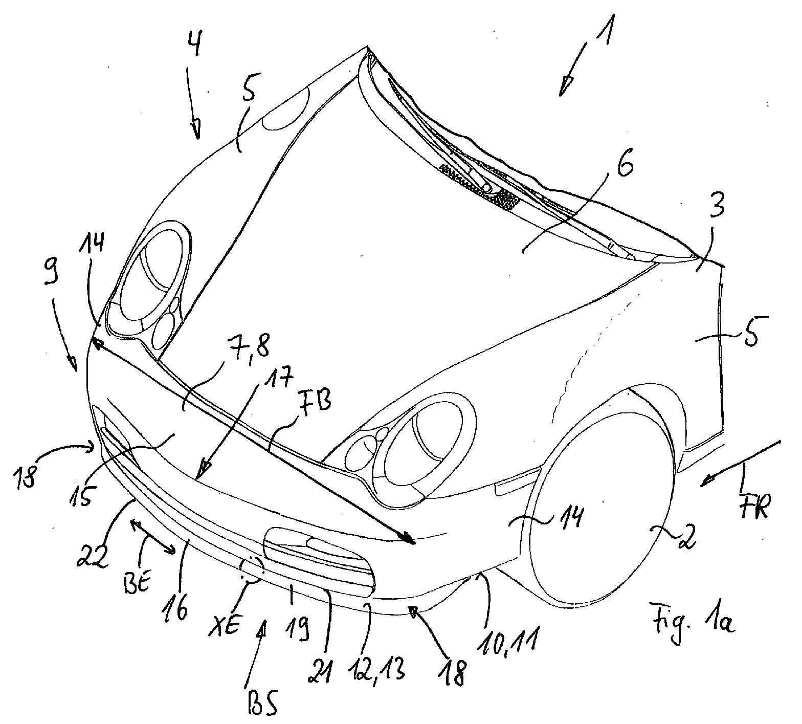
- Fig. 1a shows a detail of a motor vehicle 1, of which is carried by wheels 2 Structure 3 only a front part 4 can be seen.
- the front section 4 comprises parts of the Lateral fenders 5 forming the outer skin of the vehicle, a hood 6 arranged between them as well as a front part 7 of the hood 6 and the fenders 5, which a Cladding part 8 for a bumper arranged behind it (not shown) can represent.
- the bow part 7 therefore forms the front end 9 of the motor vehicle 1 or the front section 4.
- the motor vehicle 1 has one Vehicle width FB between the lateral longitudinal extensions 14 of the front part 7 it is measured which longitudinal extensions 14 over a base 15 of the U-shaped one Front part 7 are connected.
- the air guiding device 12 extends approximately with a strip-shaped spoiler lip 16 over the vehicle width FB and can also - as shown in Fig. 1a - in the lateral longitudinal sections 14 be guided around. Regardless of whether the spoiler lip 16 extends into the longitudinal sections 14 results in the course of the spoiler lip 16 a contour that follows the rounded contour 17 of the base 15 of the front part 7. Through her Extension into the longitudinal extensions 14 can rounded corner areas 18 of the Spoiler lip 16 may be provided.
- the air guide device 12 is in an extended, approximately upright Operating position BS shown, in which the spoiler lip 16 is directed downward Extension 19 of the bow part 7 represents what is otherwise from FIGS. 2a and 3rd emerges more clearly.
- the spoiler lip 16 acts as aerodynamic air flow control element, which the air flow while driving the Motor vehicle 1 depending on the desired specifications, such as cheaper Drag coefficient, optimized downforce, or the like.
- the Air guiding device 12 can also move from the extended operating position BS into a retracted, rearward and approximately horizontal rest position RS spent 2a and 3 by a dashed spoiler lip 16 is shown.
- the air guiding device 12 In the rest position RS, the air guiding device 12 essentially has no air flow guiding effect on motor vehicle 1. From the resting position RS in the extended operating position BS, the spoiler lip 16 via a Actuator 20 relocated, which - seen in the direction of travel FR - behind the Spoiler lip 16 is located and is described in more detail below.
- the detail of the spoiler lip 16 marked XE in FIG. 1a is shown in FIG. 1b shown enlarged.
- the spoiler lip 16 is with its upper fastening end 21 connected to the bow part 7 and its lower end forms a free end 22.
- the spoiler lip 16 is made of a fiber composite material, the matrix 23 is stretchable and is elastic and in particular made of plastic or preferably of an elastomer is made.
- the fibers 25 of the first fiber group 24 are essentially inextensible, that is, those that act on the spoiler lip 16 when the motor vehicle 1 is in motion Forces or when moving from the rest position RS to the operating position BS these fibers 25 are not subject to any or only a very insignificant one Length change.
- the spoiler lip 16 thereby receives a high degree of rigidity perpendicular to BE width extension, causing kinking or excessive bending of air flow pressure, which acts while driving the motor vehicle 1, largely is avoided.
- the material for the fibers 25 of the first fiber group 24 could be Polyester, polyamide or aramid can be used.
- a plurality of fibers 26 of a second fiber group 27 can be inserted into the matrix 23 be embedded, which run in the direction of the width extension BE of the spoiler lip 16, So along the vehicle width FB.
- the fibers are 25 the first fiber group 24 and the fibers 26 of the second fiber group 27 approximately oriented at right angles to each other and the fibers 25 run approximately at right angles to Width extension BE or the fibers 26 run parallel to the width extension BE of the spoiler lip 16.
- the fibers 26 of the second fiber group 27 are made of one stretchable material, especially plastic, made because of the rounded contour of the bow part 7 following spoiler lip 16 when extending from the rest position RS in the Operating position BS is stretched in the direction of the width BE, which is caused by the stretchable fibers 26 is insignificant or not hindered. Nevertheless, the stretchable fibers 26 the fiber composite material.
- the fibers 25 and 26 of the first and second fiber groups 24 and 27 can be used as Woven fabric, knitted fabric or knitted fabric or the like can be embedded in the matrix 23. alternative the fibers 25 and 26 could be arranged loosely to one another and only through the matrix 23 are fixed in position.
- the fibers 25 of the first fiber group 24 can also be shown in FIG several layers 28 and 29 (Fig. 2a and 3) and approximately parallel to each other be aligned, the fiber composite material preferably having one layer is made. 2a and 3 are fibers 26 of the second fiber group 27 of the Not shown for the sake of simplicity. Otherwise, the same or Identical parts with identical reference numerals.
- FIGS. 2a and 3 also show that at the free end 22 of the spoiler lip 16 a channel 30 running at right angles through the plane of the drawing in the spoiler lip 16 is formed, which therefore along the width extent BE of the spoiler lip 16 runs.
- this channel 30 there is a flexible element 31, for example a rod, in particular plastic rod KS used.
- KS plastic rod
- Around the channel 30 or the flexible Element 31 is at least one fiber strand 32 with inextensible fibers, in particular Fibers 25 of the first fiber group 24, which fiber strand 32 in the two layers 28 and 29 of the first fiber group 24. Accordingly, this runs Fiber strand 32 from an upper fastening section 33 at fastening end 21 the spoiler lip 16 down towards the free end 22, there is around the channel.
- this fiber strand 32 in at least one of the To interrupt layers 28 or 29 at at least one predefinable predetermined bending point 34, so that in the predetermined bending point 34 the number of layers 28 and 29 by one layer is reduced. In the area of the predetermined bending point 34, the rigidity of the spoiler lip 16 reduced so that a desired bending can take place here.
- the predetermined bending point 34 can be adjacent to the fastening section 33 and / or at a distance to be provided to the flap-like movement from the rest position RS in the Simplify operating position BS of the spoiler lip 16. This predetermined bending point 34 can thus form a hinge-like device.
- the fibers 25 of the first are sufficient Fiber group 24 only up to the free end 22 and to the fastening section 33 approach, so always end before.
- the predetermined bending point 34 is formed in a fiber-free region 34 '. Since that flexible element 31 in the region of the free end 22 for a sufficient Stiffness of the spoiler lip 16 can provide, in particular for manufacturing reasons to guide the fibers 25 or the fiber strand 32 around the channel 30 to be dispensed with.
- the actuating element 20 for the spoiler lip 16 is in the exemplary embodiments 2a and 3 are each inflatable and deflatable and have them at least one hose 35, which extends along the vehicle width FB or parallel for width extension BE of the spoiler lip 16 between the bottom 10 and the Rear side 36 of the spoiler lip 16 extends and in the operating position of the spoiler lip 16 - seen in the direction of travel FR - behind the spoiler lip 16 and this opposite the Bottom 10 supports.
- the hose 35 can have one or more chambers 37, 38, 39 3, which - according to FIG. 3 - lie one above the other and have an essentially oval or have an elliptical cross section, possibly with a different cross section size.
- Fig. 2a shows the chambers 37 and 38, which have an elliptical cross section, are also shown their adjacent ends attached to each other and with their spaced ends 40, 41 in the region of the free end 22 of the Spoiler lip 16 or attached to the bottom 10.
- the hose 35 with its at least one chamber 37, 38 or 39 is preferred made of the same material as the matrix and in any case includes a stretchable one and elastic material, preferably that of the matrix 23.
- the wall 42 of the hose 35 or the chambers 37 to 39 is provided with a fiber reinforcement 43 (FIG. 2b), whose fibers 44 are arranged in one or more layers LG and around the circumference UM at least one of the chambers 37 to 39 or around the circumference of the hose 35 in the wall 42 run.
- the fibers 44 are substantially inextensible, which makes them excessive inflation of the corresponding chamber 37, 38 and / or 39 or the Cross-section of the hose is avoided.
- the fibers 44 of the fiber reinforcement 43 are assigned to the inextensible fibers 25 of the first fiber group 24 and preferably made from the same material.
- the manufacture of the above is described below described spoiler lip 16 explained in more detail.
- a multi-part, for example two-part mold 45 with an upper part 46 and a lower part 47 are the Fibers 25 of the first fiber group 24 are inserted into the lower part 47 and accordingly aligned transversely to the width extent BE of the spoiler lip 16.
- an elongated core 48 inserted during the manufacturing process when introducing the starting material for the matrix 23, the space for the channel 30 within the spoiler lip 16 in the area of the end 22 keeps it free.
- the Starting material for the matrix 23 includes rubber, so that from it Heating the production mold 45 by vulcanizing an elastomer as a matrix 23 is formed.
- the mold 45 is placed on top of one another Parts 46 and 47 closed, so that for the introduction of the starting material for the Matrix 23 a cavity 49 between the recessed portion 50 of the lower part 47 and the raised portion 51 of the upper part 46 remains free.
- Starting material for the matrix 23 in the form 45 in the cavity 49 preferably introduced via a feed channel ZK.
- the spoiler lip 16 is removed from the mold 45, that is demolded, and the core 48 can be removed immediately or later.
- the flexible element 31 For example, a fiber-reinforced plastic rod KS (Fig. 4a) can be used.
- the spoiler lip 16 can be a solidified or pre-vulcanized preform manufactured and in a downstream manufacturing process in the final form brought according to Fig. 4a and thereby fully vulcanized.
- the shape 45 be designed such that the spoiler lip 16 according to FIG. 4a is finished therein can, so that the element 31 is subsequently used.
- a hollow one could be used Core 48 'in the form of an insertion tube 52 with a hollow interior 53 can be used, like this from the enlarged section XS according to section line XS - XS in Fig. 4a evident. After the spoiler lip 16 has been removed from the mold, this insertion hose 52 remains in the region of the free end 22 and the hollow interior 53 forms the channel 30 Insert hose 52 is preferably in the direction of the width extension BE Spoiler lip 16 made stretchy.
Landscapes
- Engineering & Computer Science (AREA)
- Chemical & Material Sciences (AREA)
- Mechanical Engineering (AREA)
- Composite Materials (AREA)
- Combustion & Propulsion (AREA)
- Transportation (AREA)
- Laminated Bodies (AREA)
- Body Structure For Vehicles (AREA)
- Moulding By Coating Moulds (AREA)
Abstract
Description
- Fi. 1a
- ausschnittweise ein Kraftfahrzeug mit einer Frontpartie und einer Luftleiteinrichtung,
- Fig. 1b
- eine vergrößerte Detaildarstellung der Luftleiteinrichtung nach Fig. 1a,
- Fig. 2a
- nach einem ersten Ausführungsbeispiel die Luftleiteinrichtung in Schnittdarstellung,
- Fig. 2b
- eine vergrößerte Detaildarstellung eines Betätigungselements nach Fig. 2a,
- Fig. 3
- die Luftleiteinrichtung nach einem zweiten Ausführungsbeispiel,
- Fig. 4a
- eine Spoilerlippe der Luftleiteinrichtung und
- Fig. 4b
- in Schnittdarstellung eine Herstellform für die Spoilerlippe.
Claims (18)
- Verfahren zur Herstellung einer Spoilerlippe einer Luftleiteinrichtung für ein Kraftfahrzeug, welche Spoilerlippe aus einem elastischen und dehnbaren Material gefertigt wird, dadurch gekennzeichnet, dass in eine Herstellform (45) im wesentlichen undehnbare Fasern (25) einer ersten Fasergruppe (24) eingebracht werden, die quer zur Richtung der Breitenerstreckung (BE) der Spoilerlippe (16) ausgerichtet werden, und dass in die Herstellform (45) das Ausgangsmaterial für die Matrix (23) eingebracht wird, wobei ein sich entlang eines freien Endes der Spoilerlippe (16) erstreckender Kanal (30) für ein biegeelastisches Element (31) freigelassen wird.
- Verfahren nach Anspruch 1, dadurch gekennzeichnet, dass vor dem Einbringen des Ausgangsmaterials für die Matrix (23) in die Herstellform (45) dehnbare Fasern (6) einer zweiten Fasergruppe (27) eingelegt werden, welche Fasern (26) in Richtung der Breitenerstreckung (BE) der Spoilerlippe (16) ausgerichtet werden.
- Verfahren nach Anspruch 1 oder 2, dadurch gekennzeichnet, dass die Fasern (26, 27) der ersten und/oder zweiten Fasergruppe (24, 27) als Gewebe oder Gestrick oder Gewirk in die Herstellform (45) eingelegt werden.
- Verfahren nach Anspruch 1, dadurch gekennzeichnet, dass der Faserverbundwerkstoff einschichtig gefertigt wird.
- Verfahren nach Anspruch 1, dadurch gekennzeichnet, dass nach dem Entformen der Spoilerlippe (16) das biegeelastische Element (31) in den Kanal (30) eingesetzt wird.
- Verfahren nach Anspruch 1, dadurch gekennzeichnet, dass zumindest einige Fasern (25) der ersten Fasergruppe (24) um den Kanal (30) zumindest teilweise herumgeführt werden.
- Verfahren nach Anspruch 1, dadurch gekennzeichnet, dass die Fasern (25) der ersten Fasergruppe (24) in mehreren Faserlagen (28, 29) angeordnet werden, wobei zumindest ein Faserstrang (32) in zwei Faserlagen (28, 29) gelegt wird.
- Verfahren nach Anspruch 7, dadurch gekennzeichnet, dass der Faserstrang (32) um den Kanal (30) herumgeführt wird.
- Verfahren nach Anspruch 1, dadurch gekennzeichnet, dass die Fasern (25) der ersten Fasergruppe (24) bis an den Kanal (30) herangeführt werden.
- Verfahren nach Anspruch 1, dadurch gekennzeichnet, dass ein Betätigungselement (20) an der Spoilerlippe (16) als Schlauch (35) mit zumindest einer aufblasbaren Kammer (37, 38, 39) ausgebildet wird, wobei der Schlauch (35) aus dehnbarem und elastischem Material, vorzugsweise dem der Matrix (23), hergestellt wird.
- Verfahren nach Anspruch 10, dadurch gekennzeichnet, dass der Schlauch (35) nachträglich an der entformten Spoilerlippe (16), vorzugsweise durch Vulkanisieren, befestigt wird.
- Verfahren nach Anspruch 1, dadurch gekennzeichnet, dass die Spoilerlippe (16) mit einen Befestigungsabschnitt (33) versehen wird, mit dem sie mit dem Kraftfahrzeug (1) verbindbar ist.
- Verfahren nach Anspruch 14, dadurch gekennzeichnet, dass die Fasern (25) der ersten Fasergruppe (24) bis in oder an den Befestigungsabschnitt (33) gelegt werden.
- Verfahren nach Anspruch 1, dadurch gekennzeichnet, dass durch Einlegen eines Kerns (48, 48') in die Herstellform (45) der Kanal (30) ausgespart wird.
- Verfahren nach Anspruch 16, dadurch gekennzeichnet, dass der Kern (48) entformbar ist.
- Verfahren nach Anspruch 16, dadurch gekennzeichnet, dass als Kern (48') ein Einlegeschlauch (52) verwendet wird, der nach dem Entformen der Spoilerlippe (16) darin verbleibt und dessen hohles Inneres (53) den Kanal (30) bildet.
- Verfahren nach Anspruch 1, dadurch gekennzeichnet, dass die Herstellform (45) beheizt wird und für die Matrix (23) ein Kautschuk umfassendes Ausgangsmaterial verwendet wird.
- Verfahren nach Anspruch 1, dadurch gekennzeichnet, dass in der Herstellform (45) die Spoilerlippe (16) als Vorformling hergestellt wird.
Applications Claiming Priority (2)
| Application Number | Priority Date | Filing Date | Title |
|---|---|---|---|
| DE10325652 | 2003-06-06 | ||
| DE10325652.0A DE10325652B4 (de) | 2003-06-06 | 2003-06-06 | Verfahren zur Herstellung einer Spoilerlippe einer Luftleiteinrichtung für ein Kraftfahrzeug |
Publications (2)
| Publication Number | Publication Date |
|---|---|
| EP1484166A2 true EP1484166A2 (de) | 2004-12-08 |
| EP1484166A3 EP1484166A3 (de) | 2006-02-08 |
Family
ID=33154571
Family Applications (1)
| Application Number | Title | Priority Date | Filing Date |
|---|---|---|---|
| EP04008583A Withdrawn EP1484166A3 (de) | 2003-06-06 | 2004-04-08 | Verfahren zur Herstellung einer Spoilerlippe einer Luftleiteinrichtung für ein Kraftfahrzeug |
Country Status (2)
| Country | Link |
|---|---|
| EP (1) | EP1484166A3 (de) |
| DE (1) | DE10325652B4 (de) |
Cited By (1)
| Publication number | Priority date | Publication date | Assignee | Title |
|---|---|---|---|---|
| WO2020057848A1 (de) * | 2018-09-20 | 2020-03-26 | Bayerische Motoren Werke Aktiengesellschaft | Spoilerlippe zur anordnung an einer frontpartie eines kraftfahrzeugs und kraftfahrzeug |
Families Citing this family (3)
| Publication number | Priority date | Publication date | Assignee | Title |
|---|---|---|---|---|
| DE102012020739B4 (de) * | 2012-10-23 | 2022-03-03 | Apollo Vredestein B.V. | Luftleiteinrichtung eines Kraftfahrzeugs |
| DE102015207326B4 (de) | 2015-04-22 | 2025-06-26 | Volkswagen Aktiengesellschaft | Spoilerlippe für ein Kraftfahrzeug |
| DE102020130431A1 (de) * | 2020-11-18 | 2022-05-19 | Bayerische Motoren Werke Aktiengesellschaft | Luftleitelement und Fahrzeug mit zumindest einem Luftleitelement |
Family Cites Families (4)
| Publication number | Priority date | Publication date | Assignee | Title |
|---|---|---|---|---|
| DE1795627U (de) * | 1959-06-10 | 1959-09-10 | Werner Dipl Ing Haiss | Faserverstaerkte kunststoffschale mit spanten. |
| EP0303012B1 (de) * | 1987-08-14 | 1990-10-31 | Phoenix Aktiengesellschaft | Formkörper, insbesondere Heckspoiler |
| WO2002051688A2 (de) * | 2000-12-23 | 2002-07-04 | Bayerische Motoren Werke Aktiengesellschaft | Flächiger abschnitt einer aussenhaut einer fahrzeugkarosserie |
| DE10160748B8 (de) * | 2001-12-11 | 2005-09-29 | Dr.Ing.H.C. F. Porsche Ag | Kraftfahrzeug mit einer eine Luftleiteinrichtung umfassenden Frontpartie |
-
2003
- 2003-06-06 DE DE10325652.0A patent/DE10325652B4/de not_active Expired - Lifetime
-
2004
- 2004-04-08 EP EP04008583A patent/EP1484166A3/de not_active Withdrawn
Cited By (2)
| Publication number | Priority date | Publication date | Assignee | Title |
|---|---|---|---|---|
| WO2020057848A1 (de) * | 2018-09-20 | 2020-03-26 | Bayerische Motoren Werke Aktiengesellschaft | Spoilerlippe zur anordnung an einer frontpartie eines kraftfahrzeugs und kraftfahrzeug |
| US11679822B2 (en) | 2018-09-20 | 2023-06-20 | Bayerische Motoren Werke Aktiengesellschaft | Spoiler lip for arranging on a front part of a motor vehicle, and motor vehicle |
Also Published As
| Publication number | Publication date |
|---|---|
| EP1484166A3 (de) | 2006-02-08 |
| DE10325652B4 (de) | 2015-02-05 |
| DE10325652A1 (de) | 2004-12-23 |
Similar Documents
| Publication | Publication Date | Title |
|---|---|---|
| EP1484238B1 (de) | Luftleiteinrichtung für ein Kraftfahrzeug | |
| DE10160748B4 (de) | Kraftfahrzeug mit einer eine Luftleiteinrichtung umfassenden Frontpartie | |
| DE112011105852B4 (de) | Schutzabdeckung und Verfahren zu deren Herstellung | |
| EP2513544B1 (de) | Wellrohr, rohr und frischluftanlage | |
| EP0714056B1 (de) | Einteiliges Pedal | |
| EP1316409A1 (de) | Faserverbund-Crashstruktur | |
| EP2011723A2 (de) | Luftleiteinrichtung eines Kraftfahrzeuges | |
| EP1556240A1 (de) | Dichtungsstrang für karosseriedichtungen mit bereichsweise verstärktem dichtungsprofil | |
| DE102013219820A1 (de) | Faserverbundwerkstoffbauteil, Verfahren zur Herstellung eines Faserverbundwerkstoffbauteils sowie Verwendung von Faserbündeln und Verstrebungsmitteln zur Herstellung eines Faserverbundwerkstoffbauteils | |
| EP0712777B1 (de) | Chassisaufbau aus Kunststoff für einen Rasenmäher | |
| DE2526914C3 (de) | Stoßfänger aus nachgiebigem Kunststoff für Kraftfahrzeuge | |
| EP1484237B1 (de) | Luftleiteinrichtung für ein Kraftfahrzeug | |
| DE10325652B4 (de) | Verfahren zur Herstellung einer Spoilerlippe einer Luftleiteinrichtung für ein Kraftfahrzeug | |
| EP2280186B2 (de) | Luftbalg für eine Luftfeder | |
| DE102020113399A1 (de) | Staubdichte Hülse | |
| DE102018208298A1 (de) | Koppelstange, Radaufhängung und Verfahren zur Herstellung einer Koppelstange | |
| DE102005056961A1 (de) | Verkleidungsteile-Anordnung für einen Kraftwagen | |
| DE102015207326B4 (de) | Spoilerlippe für ein Kraftfahrzeug | |
| DE102007025473B4 (de) | Luftleitvorrichtung für ein Fahrzeug | |
| EP2159035A2 (de) | Verfahren und Vorrichtung zur Herstellung eines blasgeformten, mit wenigstens einem Verstärkungselement versehenen Kunststoffhohlkörpers | |
| EP4005840B1 (de) | Windabweiser zur geräuschreduzierung an einer dachöffnung eines fahrzeugs, sowie verfahren zum herstellen eines derartigen windabweisers | |
| DE202019100377U1 (de) | Hydrofoil | |
| DE102018130327A1 (de) | Karosserieelement mit Luftleiteinrichtung und Verfahren zur Herstellung desselben | |
| DE102021127338A1 (de) | Seitenaufprallträger für kraftfahrzeug | |
| DE4401732C2 (de) | Verfahren zur Herstellung eines mit Gewebe versehenen Reifens |
Legal Events
| Date | Code | Title | Description |
|---|---|---|---|
| PUAI | Public reference made under article 153(3) epc to a published international application that has entered the european phase |
Free format text: ORIGINAL CODE: 0009012 |
|
| AK | Designated contracting states |
Kind code of ref document: A2 Designated state(s): AT BE BG CH CY CZ DE DK EE ES FI FR GB GR HU IE IT LI LU MC NL PL PT RO SE SI SK TR |
|
| AX | Request for extension of the european patent |
Extension state: AL HR LT LV MK |
|
| PUAL | Search report despatched |
Free format text: ORIGINAL CODE: 0009013 |
|
| AK | Designated contracting states |
Kind code of ref document: A3 Designated state(s): AT BE BG CH CY CZ DE DK EE ES FI FR GB GR HU IE IT LI LU MC NL PL PT RO SE SI SK TR |
|
| AX | Request for extension of the european patent |
Extension state: AL HR LT LV MK |
|
| 17P | Request for examination filed |
Effective date: 20060808 |
|
| 17Q | First examination report despatched |
Effective date: 20060831 |
|
| AKX | Designation fees paid |
Designated state(s): DE FR GB IT NL |
|
| STAA | Information on the status of an ep patent application or granted ep patent |
Free format text: STATUS: THE APPLICATION IS DEEMED TO BE WITHDRAWN |
|
| 18D | Application deemed to be withdrawn |
Effective date: 20070111 |