EP1483523B1 - Raccord avec unite de commande - Google Patents
Raccord avec unite de commande Download PDFInfo
- Publication number
- EP1483523B1 EP1483523B1 EP03706596A EP03706596A EP1483523B1 EP 1483523 B1 EP1483523 B1 EP 1483523B1 EP 03706596 A EP03706596 A EP 03706596A EP 03706596 A EP03706596 A EP 03706596A EP 1483523 B1 EP1483523 B1 EP 1483523B1
- Authority
- EP
- European Patent Office
- Prior art keywords
- connecting coupling
- connection
- coupling
- coupling according
- eccentric shaft
- Prior art date
- Legal status (The legal status is an assumption and is not a legal conclusion. Google has not performed a legal analysis and makes no representation as to the accuracy of the status listed.)
- Expired - Lifetime
Links
Images
Classifications
-
- F—MECHANICAL ENGINEERING; LIGHTING; HEATING; WEAPONS; BLASTING
- F16—ENGINEERING ELEMENTS AND UNITS; GENERAL MEASURES FOR PRODUCING AND MAINTAINING EFFECTIVE FUNCTIONING OF MACHINES OR INSTALLATIONS; THERMAL INSULATION IN GENERAL
- F16L—PIPES; JOINTS OR FITTINGS FOR PIPES; SUPPORTS FOR PIPES, CABLES OR PROTECTIVE TUBING; MEANS FOR THERMAL INSULATION IN GENERAL
- F16L37/00—Couplings of the quick-acting type
- F16L37/28—Couplings of the quick-acting type with fluid cut-off means
- F16L37/30—Couplings of the quick-acting type with fluid cut-off means with fluid cut-off means in each of two pipe-end fittings
- F16L37/32—Couplings of the quick-acting type with fluid cut-off means with fluid cut-off means in each of two pipe-end fittings at least one of two lift valves being opened automatically when the coupling is applied
- F16L37/36—Couplings of the quick-acting type with fluid cut-off means with fluid cut-off means in each of two pipe-end fittings at least one of two lift valves being opened automatically when the coupling is applied with two lift valves being actuated to initiate the flow through the coupling after the two coupling parts are locked against withdrawal
-
- F—MECHANICAL ENGINEERING; LIGHTING; HEATING; WEAPONS; BLASTING
- F17—STORING OR DISTRIBUTING GASES OR LIQUIDS
- F17C—VESSELS FOR CONTAINING OR STORING COMPRESSED, LIQUEFIED OR SOLIDIFIED GASES; FIXED-CAPACITY GAS-HOLDERS; FILLING VESSELS WITH, OR DISCHARGING FROM VESSELS, COMPRESSED, LIQUEFIED, OR SOLIDIFIED GASES
- F17C2205/00—Vessel construction, in particular mounting arrangements, attachments or identifications means
- F17C2205/03—Fluid connections, filters, valves, closure means or other attachments
- F17C2205/0302—Fittings, valves, filters, or components in connection with the gas storage device
- F17C2205/037—Quick connecting means, e.g. couplings
-
- Y—GENERAL TAGGING OF NEW TECHNOLOGICAL DEVELOPMENTS; GENERAL TAGGING OF CROSS-SECTIONAL TECHNOLOGIES SPANNING OVER SEVERAL SECTIONS OF THE IPC; TECHNICAL SUBJECTS COVERED BY FORMER USPC CROSS-REFERENCE ART COLLECTIONS [XRACs] AND DIGESTS
- Y10—TECHNICAL SUBJECTS COVERED BY FORMER USPC
- Y10T—TECHNICAL SUBJECTS COVERED BY FORMER US CLASSIFICATION
- Y10T137/00—Fluid handling
- Y10T137/8593—Systems
- Y10T137/87917—Flow path with serial valves and/or closures
- Y10T137/87925—Separable flow path section, valve or closure in each
- Y10T137/87941—Each valve and/or closure operated by coupling motion
- Y10T137/87949—Linear motion of flow path sections operates both
-
- Y—GENERAL TAGGING OF NEW TECHNOLOGICAL DEVELOPMENTS; GENERAL TAGGING OF CROSS-SECTIONAL TECHNOLOGIES SPANNING OVER SEVERAL SECTIONS OF THE IPC; TECHNICAL SUBJECTS COVERED BY FORMER USPC CROSS-REFERENCE ART COLLECTIONS [XRACs] AND DIGESTS
- Y10—TECHNICAL SUBJECTS COVERED BY FORMER USPC
- Y10T—TECHNICAL SUBJECTS COVERED BY FORMER US CLASSIFICATION
- Y10T137/00—Fluid handling
- Y10T137/8593—Systems
- Y10T137/87917—Flow path with serial valves and/or closures
- Y10T137/87981—Common actuator
Definitions
- the invention relates to a connection coupling for the transmission of gaseous and / or liquid fluids, in particular for filling vehicle gas tanks.
- connection couplings With such connection couplings, a secure and quickly connectable transmission of a fluid from a pressure source, for example, from a refueling system to a vehicle to be achieved. Particularly important here is the simple and safe operation, so that even at high refueling pressures of 200 bar (20 MPa) and more trouble-free handling is possible.
- US-A-4,212,411 describes a connection coupling, which includes all the features of the preamble of claim 1.
- connection coupling is also in the WO 98/05898 the applicant described, wherein the quick-connect coupling comprises a housing having a fluid inlet and a fluid outlet, and a plurality of valves are provided to ensure a secure seal of the quick-connect coupling until complete connection.
- These valves are switched after applying the quick-connect coupling by turning a control lever in a certain predetermined order, first by the sliding of the quick-release coupling to a nipple the exhaust valve is opened, then upon further movement of the control lever serving as locking elements collets are closed and finally the Inlet valve is opened.
- the control lever is in this case via an eccentric shaft with the sliding sleeve for the application of the collets and with a sealing piston in engagement, which also releases the fluid inlet after the connection of the plug-in coupling.
- control lever By twisting the connection hoses, the control lever can assume an unfavorable position (eg to the right), which is extremely uncomfortable for a left-hander when operating the connection coupling.
- connection coupling has been proven by its particularly secure connection option, it is still able to be improved in terms of handling.
- the invention has for its object to provide a connection coupling, in particular as a quick-release coupling of the type mentioned above, which allows a particularly simple handling with a compact design.
- connection coupling is particularly suitable for use in a quick connection coupling for refueling Erdgasfahreugen, resulting in a particularly simple and compact design, since the control lever is formed together with the switching unit around the central axis rotatable and thus assume during the connection process each desired by the operator rotational position can.
- the switching unit can be rotated in a preferred embodiment by the opposing annular slide in a suitable position for the operator, resulting in a particularly safe and convenient handling.
- connection coupling By integrated within the connection passage through slots in the middle housing part a secure guidance of the switching unit is achieved and thus achieves a stable and compact construction of the connection coupling. Since the switching unit is outside the pressure range, a simple and smooth handling is ensured, so that the quick-connect coupling can be easily connected even by laymen.
- a vent hole is preferably provided in the housing of the switching unit. This one will preferably closed with a sintered filter or a similar material, wherein a dirt entry is avoided.
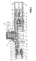
- connection coupling 10 in the form of a so-called.
- Quick connection coupling shown, which is coupled to a here indicated on the left connecting nipple 30.
- the connection coupling 10 has a tubular housing 11 with a plurality of housing parts 11a, 11b and 11c screwed together, the right housing part 11c serving as the inlet area 12 and the left area as the outlet 13 for the forwarding of the fluid to be transferred to the connection nipple 30.
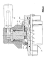
- a switching unit 21 with control lever 50 is arranged around the middle housing part 11b (cf. Fig. 2 ).
- the inlet region 12 has a connection adapter 14 to which a fluid line 12 'for supplying the fluid to be transferred can be connected via a thread.
- the connection adapter 14 with a filter sleeve inserted can be designed accordingly in adaptation to the fluid to be transferred, in particular to the respective desired Zurioshong, passage cross sections, etc.
- a plurality of elongated collets 15, which are arranged in the form of tubes, are provided, which can be spread radially outward shortly before being placed on the connecting nipple 30.
- the elongated collets 15 are - as by the aforementioned prior art known - biased by an annular spring 16, so that the collets 15 are radially spread outwards.
- the collets 15 At the here left outer end with inwardly cranked surfaces, the collets 15 each corresponding to a groove-shaped connection profile of the connecting nipple 30 formed positive engagement profiles 17.
- Their construction is also described in detail in the aforementioned prior art, so that it is possible to dispense with a further explanation here.
- a discharge valve forming sealing piston 22 which has at its front end face a conical sealing surface 23 for engagement with a sealing ring of the connecting nipple 30, so that the substantially along the central axis of the Coupling 10 flowing gaseous and / or liquid fluid can not escape to the outside.
- the provided on the sealing piston 22 outlet valve 25 seals by means of a sealing ring as a valve seat 26 relative to the sealing piston 22 in the closed position.
- the outlet valve 25 is acted upon by a compression spring 28, which is supported on the right side towards a slide valve 27 of the switching unit 21.
- the slide switch 27 is when uncoupling the connection coupling 10 from the connection nipple 30 through the switching unit 21 along the Coupling axis shifted and thus forms together with a sealing washer 24 a vent valve 35th
- vent valve 35 and the slide switch 27 are in this case actuated by pivoting the control lever 50, since the associated, mounted in a sleeve 52 eccentric shaft 51 is coupled to the slide switch 27, namely by engagement of a plurality of bolts 29 which are slidably inserted into axial slots 32 and with an outer annular slide 31 in conjunction.
- This has an annular groove, in which engages the lower end of the eccentric shaft 51 here.
- the entire switching unit 21 with the control lever 50 is rotatable about this annular slide 31, since the sleeve 52 is rotatably mounted on the outer circumference of the central housing part 11b.
- connection position of the connection coupling 10 shown here the engagement profile 17 of the collets 15 is brought into engagement with the connection nipple 30 when plugged onto the connection nipple 30.
- the sliding sleeve 18 is pushed over the collets 15 and this thus locked.
- pressurization beginning of refueling process
- the sealing piston 22 is first moved (also under the action of the spring 28) to the left.
- the valve seat 26 on the sealing piston 22 and thus the outlet valve 25 are also opened with displacement of the sealing piston 22 to the right.
- the engagement profile 17 has already intervened on the correspondingly formed connection profile of the connecting nipple 30, wherein the axial movement of the sliding sleeve 18 engages over the radially outer ends of the collets 15, so that they are held in a form-fitting manner at the connection nipple 30.
- the sliding sleeve 18 after turning the control lever 50 of the compression spring 19 pushed back. After a short distance, the collets 15 can again spread radially outward.
- the sealing piston 22 since the fluid pressure has been interrupted (eg by closing a refueling valve), the sealing piston 22 is here shifted to the right in the direction of the inlet region 12, and the outlet valve 25 is closed at the valve seat 26.
- an inlet valve 45 is further arranged with an associated valve seat 46 centrally in the housing 11 and the housing part 11c of the connection coupling 10.
- the inlet valve 45 is also axially displaceable by the control lever 50 and its eccentric shaft 51 by the coupling with the slide valve 27.
- This slide valve 27 moves namely on the sealing disk 24 in the connection position shown a valve spool 47 of the inlet valve 45 in the open position, so that the inflowing from the inlet portion 12 fluid through the valve spool 47 and a passage in the sealing washer 24 and the tubular slide valve 27 to the outlet 13th can flow.
- connection coupling 10 When loosening the connecting coupling 10 (by about 180 °) of the switching slide 27 is moved over the bolts 29 to the left by turning the control lever 50, so that the sealing washer 24 can be released from the sealing engagement. In this case, the pressure within the connection coupling 10 can be reduced via passage slots 36 to a pressure equalization chamber 44.
- venting valve 35 is thus opened by the eccentric shaft 51 and the slide switch 27 when uncoupling the connection coupling 10.
- This still pending pressure medium flows through the pressure compensation chamber 44 to a vent hole 43 which extends parallel to the central fluid passage (through the valves 45, 35 and 25) in the housing part 11c of the connection coupling 10.
- the vent hole 43 opens into the second conduit 12 ", which is preferably designed as a return hose and as well the supply line is bounded by a housing cap 48 to serve as a handle for easy handling.
- the vent line 12 "and the adapter 14 connected to the fluid line 12 'thus always at least substantially parallel to each other.
- Fig. 2 the switching unit 21 is shown enlarged, wherein in the sleeve 52 for a possible pressure reduction nor a vent hole 33 is provided.
- a filter disk 34 in particular a sintered filter and is opposite to the annular slide 31 in the axial direction, which is movable by means of the eccentric shaft 51 in the axial direction and thereby axially displaces the inner slide valve 27 by a few centimeters on the Bolzem 29, as far as through the Length of the axial slots 32 is possible.
Landscapes
- Engineering & Computer Science (AREA)
- General Engineering & Computer Science (AREA)
- Mechanical Engineering (AREA)
- Quick-Acting Or Multi-Walled Pipe Joints (AREA)
- Filling Or Discharging Of Gas Storage Vessels (AREA)
- Loading And Unloading Of Fuel Tanks Or Ships (AREA)
Claims (6)
- Raccord dévolu au transfert de fluides gazeux et/ou liquides, notamment en vue du remplissage de réservoirs à gaz de véhicules, comportant une unité de commutation (21) conçue pour actionner des vannes (35) par l'intermédiaire d'un tiroir de distribution (27), ledit tiroir de distribution (27) étant couplé à un anneau coulissant extérieur (31) par l'intermédiaire d'au moins un tenon (29),
caractérisé par le fait que
l'unité de commutation (21) comprend un levier de commande (50) et un arbre à excentrique (51), lequel arbre à excentrique (51) pénètre dans une rainure annulaire périphérique pratiquée dans l'anneau coulissant (31), ledit arbre à excentrique (51) étant logé dans une douille (52) montée, à rotation de 360°, sur le pourtour de la partie centrale (11b) du carter. - Raccord selon la revendication 1, caractérisé par le fait que plusieurs tenons (29), notamment au nombre de quatre, sont prévus entre le tiroir de distribution (27) et l'anneau coulissant extérieur (31).
- Raccord selon la revendication 2, caractérisé par le fait que les tenons (29) sont guidés dans des fentes axiales (32) ménagées dans la partie centrale (11b) du carter dudit raccord (10).
- Raccord selon la revendication 1, caractérisé par le fait que la douille (52) présente un trou d'évent (33).
- Raccord selon la revendication 4, caractérisé par le fait que le trou d'évent (33) est occulté par un disque de filtration (34).
- Raccord selon la revendication 5, caractérisé par le fait que le disque de filtration (34) est réalisé sous la forme d'un filtre en matière frittée.
Applications Claiming Priority (3)
| Application Number | Priority Date | Filing Date | Title |
|---|---|---|---|
| DE20203296U | 2002-03-02 | ||
| DE20203296U DE20203296U1 (de) | 2002-03-02 | 2002-03-02 | Anschlußkupplung mit Schalteinheit |
| PCT/EP2003/002111 WO2003074923A1 (fr) | 2002-03-02 | 2003-03-01 | Raccord avec unite de commande |
Publications (2)
| Publication Number | Publication Date |
|---|---|
| EP1483523A1 EP1483523A1 (fr) | 2004-12-08 |
| EP1483523B1 true EP1483523B1 (fr) | 2013-01-02 |
Family
ID=7968482
Family Applications (1)
| Application Number | Title | Priority Date | Filing Date |
|---|---|---|---|
| EP03706596A Expired - Lifetime EP1483523B1 (fr) | 2002-03-02 | 2003-03-01 | Raccord avec unite de commande |
Country Status (8)
| Country | Link |
|---|---|
| US (1) | US7267140B2 (fr) |
| EP (1) | EP1483523B1 (fr) |
| JP (1) | JP4198067B2 (fr) |
| CN (1) | CN1289850C (fr) |
| AU (1) | AU2003208781A1 (fr) |
| CA (1) | CA2487682C (fr) |
| DE (1) | DE20203296U1 (fr) |
| WO (1) | WO2003074923A1 (fr) |
Families Citing this family (11)
| Publication number | Priority date | Publication date | Assignee | Title |
|---|---|---|---|---|
| DE20203247U1 (de) * | 2002-03-02 | 2003-04-17 | Weh, Erwin, 89257 Illertissen | Anschlußkupplung mit Datenschnittstelle |
| DE20203246U1 (de) | 2002-03-02 | 2003-04-17 | Weh, Erwin, 89257 Illertissen | Anschlußkupplung mit Schiebehülse und Spannzangen |
| DE20203248U1 (de) | 2002-03-02 | 2003-04-17 | Weh, Erwin, 89257 Illertissen | Anschlußkupplung |
| DE202007018142U1 (de) * | 2007-12-22 | 2009-03-05 | Weh, Erwin | Kupplung, insbesondere für LNG |
| DE102010025747A1 (de) * | 2010-06-30 | 2012-01-05 | Erwin Weh | Schnellanschluss |
| US9175795B2 (en) | 2012-05-29 | 2015-11-03 | Parker-Hannifin Corporation | Coupling with locking bars |
| CA2982830A1 (fr) | 2015-04-24 | 2016-10-27 | Cmd Corporation | Procede et appareil servant a des fins de distribution de carburant gazeux a un vehicule |
| JP6830230B2 (ja) * | 2016-05-30 | 2021-02-17 | レッキス工業株式会社 | 管継手のクランプ装置 |
| AT519159B1 (de) * | 2016-09-16 | 2018-09-15 | Avl Ditest Gmbh | Anschlussadapter, insbesondere für Klimaanlagen |
| WO2020053628A1 (fr) * | 2018-09-14 | 2020-03-19 | Weh Gmbh, Verbindungstechnik | Système d'étanchéité pour fluides gazeux |
| CN110848561B (zh) * | 2019-10-16 | 2024-06-28 | 北京航天试验技术研究所 | 一种液氢加注装置 |
Family Cites Families (10)
| Publication number | Priority date | Publication date | Assignee | Title |
|---|---|---|---|---|
| US3731705A (en) * | 1970-05-06 | 1973-05-08 | Lear Siegler Inc | Fluid coupling |
| US3710823A (en) * | 1971-01-25 | 1973-01-16 | Dempco | Hydraulic coupler with cam actuator |
| US4074698A (en) * | 1976-07-26 | 1978-02-21 | Seymour Manufacturing Co., Inc. | Hydraulic coupler |
| US4181150A (en) * | 1977-09-12 | 1980-01-01 | Gould, Inc. | Lever-type quick disconnect coupling |
| US4222411A (en) * | 1979-01-19 | 1980-09-16 | Parker-Hannifin Corporation | Lever actuated fluid coupling |
| US4347870A (en) * | 1980-05-14 | 1982-09-07 | Gould Inc. | Lever-type quick disconnect coupling |
| US4533115A (en) * | 1983-04-06 | 1985-08-06 | Sloan Valve Company | Gladhand with dirt protection plug |
| DE29612942U1 (de) * | 1996-07-30 | 1997-09-04 | Weh Gmbh, Verbindungstechnik, 89257 Illertissen | Schnellanschlußkupplung |
| DE29613134U1 (de) | 1996-08-01 | 1997-09-04 | Weh Gmbh, Verbindungstechnik, 89257 Illertissen | Drehdurchführung |
| DE29903613U1 (de) * | 1999-03-01 | 2000-04-13 | Weh, Erwin, 89257 Illertissen | Betätigungsvorrichtung, insbesondere an einer Schnellanschlußkupplung |
-
2002
- 2002-03-02 DE DE20203296U patent/DE20203296U1/de not_active Expired - Lifetime
-
2003
- 2003-03-01 EP EP03706596A patent/EP1483523B1/fr not_active Expired - Lifetime
- 2003-03-01 JP JP2003573339A patent/JP4198067B2/ja not_active Expired - Lifetime
- 2003-03-01 WO PCT/EP2003/002111 patent/WO2003074923A1/fr active Application Filing
- 2003-03-01 CN CN03807171.1A patent/CN1289850C/zh not_active Expired - Lifetime
- 2003-03-01 US US10/506,568 patent/US7267140B2/en not_active Expired - Lifetime
- 2003-03-01 CA CA2487682A patent/CA2487682C/fr not_active Expired - Lifetime
- 2003-03-01 AU AU2003208781A patent/AU2003208781A1/en not_active Abandoned
Also Published As
| Publication number | Publication date |
|---|---|
| CN1643292A (zh) | 2005-07-20 |
| CA2487682C (fr) | 2012-01-03 |
| US7267140B2 (en) | 2007-09-11 |
| JP4198067B2 (ja) | 2008-12-17 |
| CN1289850C (zh) | 2006-12-13 |
| CA2487682A1 (fr) | 2003-09-12 |
| JP2006508299A (ja) | 2006-03-09 |
| DE20203296U1 (de) | 2003-04-17 |
| WO2003074923A1 (fr) | 2003-09-12 |
| EP1483523A1 (fr) | 2004-12-08 |
| US20050161097A1 (en) | 2005-07-28 |
| AU2003208781A1 (en) | 2003-09-16 |
Similar Documents
| Publication | Publication Date | Title |
|---|---|---|
| EP0916057B1 (fr) | Dispositif d'accouplement a raccord rapide | |
| EP2354626B1 (fr) | Pistolet de remplissage composé d'un pistolet de remplissage de base et d'une interface et système modulaire composé d'un pistolet de remplissage de base et d'une multitude d'interfaces | |
| EP1883766B1 (fr) | Dispositif d'actionnement pour raccord rapide | |
| EP0983461B1 (fr) | Accouplement a connexion rapide | |
| EP1483523B1 (fr) | Raccord avec unite de commande | |
| EP1483195B1 (fr) | Raccord avec interface de donnees | |
| DE20203246U1 (de) | Anschlußkupplung mit Schiebehülse und Spannzangen | |
| EP1159558B1 (fr) | Dispositif de commande notamment d'un dispositif d'accouplement a action rapide | |
| EP1437543B1 (fr) | Dispositif d'accouplement à raccord rapide avec dispositif de manoeuvre pour le transfert d'un milieu gazeux et/ou liquide | |
| EP1483524B1 (fr) | Couplage de connexion | |
| EP1690037B1 (fr) | Dispositif d'actionnement pour couplage a raccordement rapide | |
| DE102004014461B4 (de) | Rohrkupplung | |
| DE29613134U1 (de) | Drehdurchführung | |
| EP3781857A1 (fr) | Raccord et procédé de transmission de fluides | |
| EP1847757B1 (fr) | Dispositif d'accouplement à raccord rapide avec dispositif de manoeuvre | |
| EP2047170B1 (fr) | Soupape de commande à coulisseau | |
| DE29709040U1 (de) | Schnellanschlußkupplung |
Legal Events
| Date | Code | Title | Description |
|---|---|---|---|
| PUAI | Public reference made under article 153(3) epc to a published international application that has entered the european phase |
Free format text: ORIGINAL CODE: 0009012 |
|
| 17P | Request for examination filed |
Effective date: 20040930 |
|
| AK | Designated contracting states |
Kind code of ref document: A1 Designated state(s): AT BE BG CH CY CZ DE DK EE ES FI FR GB GR HU IE IT LI LU MC NL PT RO SE SI SK TR |
|
| 17Q | First examination report despatched |
Effective date: 20090223 |
|
| GRAP | Despatch of communication of intention to grant a patent |
Free format text: ORIGINAL CODE: EPIDOSNIGR1 |
|
| GRAS | Grant fee paid |
Free format text: ORIGINAL CODE: EPIDOSNIGR3 |
|
| GRAA | (expected) grant |
Free format text: ORIGINAL CODE: 0009210 |
|
| AK | Designated contracting states |
Kind code of ref document: B1 Designated state(s): DE FR IT |
|
| REG | Reference to a national code |
Ref country code: DE Ref legal event code: R096 Ref document number: 50314653 Country of ref document: DE Effective date: 20130307 |
|
| PLBE | No opposition filed within time limit |
Free format text: ORIGINAL CODE: 0009261 |
|
| STAA | Information on the status of an ep patent application or granted ep patent |
Free format text: STATUS: NO OPPOSITION FILED WITHIN TIME LIMIT |
|
| 26N | No opposition filed |
Effective date: 20131003 |
|
| REG | Reference to a national code |
Ref country code: DE Ref legal event code: R097 Ref document number: 50314653 Country of ref document: DE Effective date: 20131003 |
|
| REG | Reference to a national code |
Ref country code: FR Ref legal event code: PLFP Year of fee payment: 14 |
|
| REG | Reference to a national code |
Ref country code: FR Ref legal event code: PLFP Year of fee payment: 15 |
|
| REG | Reference to a national code |
Ref country code: FR Ref legal event code: PLFP Year of fee payment: 16 |
|
| REG | Reference to a national code |
Ref country code: DE Ref legal event code: R082 Ref document number: 50314653 Country of ref document: DE Representative=s name: KIPAT PATENTANWAELTE, DE |
|
| PGFP | Annual fee paid to national office [announced via postgrant information from national office to epo] |
Ref country code: DE Payment date: 20211228 Year of fee payment: 20 |
|
| PGFP | Annual fee paid to national office [announced via postgrant information from national office to epo] |
Ref country code: IT Payment date: 20220322 Year of fee payment: 20 Ref country code: FR Payment date: 20220322 Year of fee payment: 20 |
|
| REG | Reference to a national code |
Ref country code: DE Ref legal event code: R071 Ref document number: 50314653 Country of ref document: DE |
|
| P01 | Opt-out of the competence of the unified patent court (upc) registered |
Effective date: 20230530 |