EP1482637A1 - Method of influencing an input signal and predistorter - Google Patents
Method of influencing an input signal and predistorter Download PDFInfo
- Publication number
- EP1482637A1 EP1482637A1 EP20030291281 EP03291281A EP1482637A1 EP 1482637 A1 EP1482637 A1 EP 1482637A1 EP 20030291281 EP20030291281 EP 20030291281 EP 03291281 A EP03291281 A EP 03291281A EP 1482637 A1 EP1482637 A1 EP 1482637A1
- Authority
- EP
- European Patent Office
- Prior art keywords
- correction signal
- input signal
- base functions
- signal
- input
- Prior art date
- Legal status (The legal status is an assumption and is not a legal conclusion. Google has not performed a legal analysis and makes no representation as to the accuracy of the status listed.)
- Granted
Links
Images


Classifications
-
- H—ELECTRICITY
- H03—ELECTRONIC CIRCUITRY
- H03F—AMPLIFIERS
- H03F1/00—Details of amplifiers with only discharge tubes, only semiconductor devices or only unspecified devices as amplifying elements
- H03F1/32—Modifications of amplifiers to reduce non-linear distortion
- H03F1/3241—Modifications of amplifiers to reduce non-linear distortion using predistortion circuits
- H03F1/3252—Modifications of amplifiers to reduce non-linear distortion using predistortion circuits using multiple parallel paths between input and output
-
- H—ELECTRICITY
- H03—ELECTRONIC CIRCUITRY
- H03F—AMPLIFIERS
- H03F1/00—Details of amplifiers with only discharge tubes, only semiconductor devices or only unspecified devices as amplifying elements
- H03F1/32—Modifications of amplifiers to reduce non-linear distortion
- H03F1/3241—Modifications of amplifiers to reduce non-linear distortion using predistortion circuits
- H03F1/3258—Modifications of amplifiers to reduce non-linear distortion using predistortion circuits based on polynomial terms
-
- H—ELECTRICITY
- H03—ELECTRONIC CIRCUITRY
- H03F—AMPLIFIERS
- H03F1/00—Details of amplifiers with only discharge tubes, only semiconductor devices or only unspecified devices as amplifying elements
- H03F1/32—Modifications of amplifiers to reduce non-linear distortion
- H03F1/3241—Modifications of amplifiers to reduce non-linear distortion using predistortion circuits
- H03F1/3294—Acting on the real and imaginary components of the input signal
Definitions
- the present invention relates to a method of influencing an input signal, in particular an input signal of a power amplifier of a wireless communication system, wherein said input signal has a range of input amplitudes, wherein a correction signal depending on said input signal is generated, and wherein said input signal is influenced depending on said correction signal
- the present invention also relates to a predistorter for influencing an input signal, in particular an input signal of a power amplifier of a wireless communication system, wherein said input signal has a range of input amplitudes, wherein a correction signal depending on said input signal is generated, and wherein said input signal is influenced depending on said correction signal.
- the input signal is predistorted by a predistorter prior to feeding it to said power amplifier.
- the predistorter distorts or shapes, respectively, the characteristic of the input signal in a manner opposite to the distortion caused by said power amplifier, and in a well-tuned system an overall distortion of said input signal may thus be avoided.
- Said predistortion is usually achieved by multiplying said input signal by a correction signal or by adding such a correction signal which depends on said input signal.
- Contemporary methods use so-called polynomial predistorters wherein the correction signal is based on a polynomial. Since each function value of a polynomial depends on all coefficients of said polynomial, it is not possible to tune the correction signal or certain intervals of it, respectively, via changing one or few coefficients without changing the complete correction signal. As a further disadvantage, said polynomial predistorter only works well for a limited range of input amplitudes and is thus not flexible with respect to a varying mean power of said input signal. Furthermore, the polynomial predistorter is not flexible enough with respect to special required shapes of a characteristic of the non-linear power amplifier.
- Another solution known from prior art employs a lookup table to determine function values of said correction signal. Consequently, it is possible to configure a predistorter wherein each function value depends on one parameter that can be read from said lookup table. This solution also lacks flexibility, because especially in adaptive systems, where a dynamic modification of said parameters is required, the number of parameters that must be updated is too high.
- the generation of said correction signal is based on a plurality of base functions, and said range of input amplitudes is divided into intervals, wherein each of said base functions contributes to said correction signal in a limited number of intervals.
- a variant of the inventive method is characterized in that a set of base functions contributes to said correction signal only in a corresponding interval and/or in a limited number of neighbour intervals. I.e. changing such a base function will affect the corresponding interval and a limited number of neighbour intervals thus affecting a portion of said correction signal that is larger than one single interval but yet significantly smaller than the whole correction signal.
- base functions of neighbour intervals may overlap each other.
- Contributing to said correction signal in this sense of the present invention means to significantly change the correction signal, regardless of the mode by which said change is performed. I.e. if various base functions are added together, a contribution in the sense of the present invention means that said base functions have non-zero function values large enough to change the resulting sum in a noticeable way.
- a base function may also have non-zero function values and may not contribute to said correction signal in the above sense, as long as said non-zero function values are very small compared to any other function value of the above mentioned sum.
- said base functions are chosen such that said correction signal and a first and/or higher derivatives of said correction signal are continuous. This enables the correction signal to be modified by changing said base functions or coefficients of said base functions or the like while maintaining a smooth correction signal. Algorithms for changing said base functions must hence not obey any restriction to changing said base functions in order to maintain a smooth correction signal.
- a further variant of the invention is characterized in that said base functions have non-zero function values within a number of neighbour intervals and function values and/or derivatives of first or higher order of zero at all but one interval bounds of said neighbour intervals, in that either a function value or a derivative of said base functions is different from zero at one interval bound of said neighbour intervals, and in that said base functions are smooth.
- a maximum of four different base functions has non-zero function values at a distinct input amplitude, i.e. at a distinct interval of said range of input amplitudes.
- said four different base functions may have rather small function values, either, that do not contribute to said correction signal in said interval significantly, or in case said base functions are multiplied with each other, they may as well have function values of about one in order not to contribute to said correction signal significantly.
- said input signal x is a complex variable
- r(x) may e.g. be chosen as an absolute value of said input signal, if the correction signal is desired to only depend on the input signal's amplitude.
- the base functions ⁇ i ,i 0,.., N- 1, in turn, depend on r(x).
- the coefficients may also attain a value of zero, if a reduced number of base functions is sufficient for shaping the desired correction signal.
- At least one of said base functions is a polynomial, in particular a polynomial of third order, which allows an easy evaluation of function values and a simple base function definition.
- the range ( r 0 ,.., r M- 1 ) of input amplitudes is subdivided into M-1 intervals ( r 0 ,r 1 ),( r 1 , r 2 ),....,( r M- 2 , r M- 1 ). wherein for each interval corresponding base functions are defined.
- Each of said base functions has only a local effect on said correction signal in that for each interval ( r i , r i +1 ) not more than four base functions have non-zero function values.
- At least one of said auxiliary functions ⁇ 0 ( s ), ⁇ 1 ( s ), ⁇ 2 ( s ), ⁇ 3 ( s ) is stored to / read from a lookup table in a further advantageous embodiment of the present invention.
- a further advantageous embodiment of the method according to the present invention is characterized in that said input signal is delayed before being influenced by said correction signal, which may be necessary in most cases and depends on the computation time required for obtaining said correction signal from said input signal.
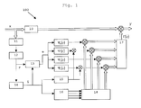
- a predistorter 100 receives a complex input signal x which, after a certain delay realised by delay means 10, is multiplied by a complex correction signal ⁇ ( x ) that depends on said input signal x. Said delay caused by the delay means 10 accounts for a computation time required by the predistorter 100 to calculate the correction signal ⁇ (x) out of the input signal x.
- r(x) corresponds to an amplitude of said input signal x.
- the square root calculation operation performed within calculation means 12 may be approximated by a polynomial. This is particularly useful if the predistorter 100 is realized on e.g. a digital signal processor (DSP).
- DSP digital signal processor
- interval number evaluation means 14 After obtaining said absolute value r(x), which in the following explanations will be referred to as amplitude r of said input signal, a corresponding interval number is evaluated by interval number evaluation means 14.
- the correction signal for the interval ( r i , r i +1 ) only depends on four of said N base functions: ⁇ 2 i ( r ( x )), ⁇ 2 i+ 1 ( r ( x )), ⁇ 2 i+ 2 ( r ( x )), ⁇ 2 i+ 3 ( r ( x )), and on the respective coefficients.
- said portion of the correction signal may individually be shaped according to system requirements concerning an optimal predistortion of said input signal x without influencing other portions of said correction signal.
- This "local effect” is achieved by limiting the number of base functions that contribute to said correction signal ⁇ (x) and by providing extra sets of base functions ⁇ 2i (r(x)), ⁇ 2i+1 (r(x)), ⁇ 2i+2 (r(x)), ⁇ 2i+3 (r(x)) for individual intervals.
- the base functions ⁇ i ( r ) and their first derivatives are continuous, and the coefficients of the polynomials the base functions ⁇ i ( r ) are composed of are defined by function values of and derivatives of the respective base function at three subsequent input signal amplitudes.
- the base functions can be divided into two different classes, the even-numbered base functions ⁇ 2 i ( r ) and the odd-numbered base functions ⁇ 2 i +1 ( r ).
- the values of even-numbered coefficients ⁇ 2i , ⁇ 2i+2 ,.. define function values of said correction signal ⁇ ( x ) at said input amplitudes r i
- the values of odd-numbered coefficients ⁇ 2i+1 , ⁇ 2i+3 ,... define derivatives of said correction signal ⁇ ( x ) at said input amplitudes r i .
- correction signal ⁇ ( x ) Due to the definition of the correction signal ⁇ ( x ), its smoothness is guaranteed for arbitrary coefficient values, and the correction signal ⁇ ( x ) is suitable for approximating a required shape/characteristic in the complete range of input amplitudes r i .
- index variable i is fed to an address calculation system 16 which calculates memory addresses of the required complex coefficients of said base functions and outputs said memory addresses to a coefficient memory 18 which provides the selected coefficients to complex multipliers, cf. Fig. 2.
- Said auxiliary functions can be pre-calculated and the resulting functions values can be stored to / read from a lookup table.
- block 15 calculates an interval width r i +1 - r i which is required for obtaining said base functions out of said auxiliary functions ⁇ 0 , ⁇ 1 , ⁇ 2 , ⁇ 3 .
- the interval width r i+ 1 -r i can also be stored to a lookup table.
- auxiliary functions ⁇ 1 , ⁇ 3 need not be multiplied with said interval width r i+ 1 -r i , if said interval width r i+ 1 -r i is constant for each value of said index variable i.
- the corresponding multipliers of the predistorter 100 of Fig. 1 may be omitted in this case, as well as block 15.
- the presented method and predistorter advantageously provide a correction signal ⁇ ( x ) and an output signal y which is a linear function of a real part of the coefficients ⁇ i , of an imaginary part of the coefficients ⁇ i and of the coefficients ⁇ i themselves, too, which is very useful for some adaptation algorithms.
- the number of coefficients for the base functions is very small which enables the method to be used in systems with limited feedback information, where only a small number of coefficients can be adapted to optimally shape the characteristic of the correction signal.
- the predistorter according to the present invention is therefore not as sensitive to power variations of the input signal as prior art polynomial predistorters.
- any desired characteristic of the correction signal can be implemented more easily as compared to a prior art lookup table approach.
- the proposed method does also enable a faster adaptation as is given with contemporary lookup table solutions.
- the method according to the present invention and/or the predistorter are not limited to be used with a power amplifier, they may be used with any non-linear device or channel which requires a process of predistortion.
Abstract
Description
- The present invention relates to a method of influencing an input signal, in particular an input signal of a power amplifier of a wireless communication system, wherein said input signal has a range of input amplitudes, wherein a correction signal depending on said input signal is generated, and wherein said input signal is influenced depending on said correction signal
- The present invention also relates to a predistorter for influencing an input signal, in particular an input signal of a power amplifier of a wireless communication system, wherein said input signal has a range of input amplitudes, wherein a correction signal depending on said input signal is generated, and wherein said input signal is influenced depending on said correction signal.
- These methods and corresponding predistorters are per se known from prior art and they are used to shape an input signal before said input signal is fed into a power amplifier. The power amplifier itself usually has a nonlinear characteristic which is undesirable since it causes the input signal to be distorted, i.e. a gain imparted on said input signal by said power amplifier is not constant but depends on an amplitude of said input signal.
- To avoid this unwanted distortion, the input signal is predistorted by a predistorter prior to feeding it to said power amplifier. The predistorter distorts or shapes, respectively, the characteristic of the input signal in a manner opposite to the distortion caused by said power amplifier, and in a well-tuned system an overall distortion of said input signal may thus be avoided. Said predistortion is usually achieved by multiplying said input signal by a correction signal or by adding such a correction signal which depends on said input signal.
- Contemporary methods use so-called polynomial predistorters wherein the correction signal is based on a polynomial. Since each function value of a polynomial depends on all coefficients of said polynomial, it is not possible to tune the correction signal or certain intervals of it, respectively, via changing one or few coefficients without changing the complete correction signal. As a further disadvantage, said polynomial predistorter only works well for a limited range of input amplitudes and is thus not flexible with respect to a varying mean power of said input signal. Furthermore, the polynomial predistorter is not flexible enough with respect to special required shapes of a characteristic of the non-linear power amplifier.
- Another solution known from prior art employs a lookup table to determine function values of said correction signal. Consequently, it is possible to configure a predistorter wherein each function value depends on one parameter that can be read from said lookup table. This solution also lacks flexibility, because especially in adaptive systems, where a dynamic modification of said parameters is required, the number of parameters that must be updated is too high.
- Therefore, it is an object of the present invention to provide an improved method of influencing an input signal and a corresponding predistorter which provide increased flexibility.
- This object is achieved by a method comprising the features of claim 1 and by a predistorter according to claim 14.
- According to the present invention, the generation of said correction signal is based on a plurality of base functions, and said range of input amplitudes is divided into intervals, wherein each of said base functions contributes to said correction signal in a limited number of intervals.
- Hence it is possible to shape a desired characteristic of said correction signal more accurately as compared to the approach using one polynomial for the definition of the whole correction signal, because changing one base function or its coefficients or the like does not affect the whole correction signal but only some portions of the correction signal which correspond to the intervals in which said changed base function contributes to the correction signal.
- The other portions of said correction signal remain unchanged, because of which the mechanism may also be said to have a "local effect" on said correction signal, and which enables an elaborated adaption of said correction signal.
- To control the local effect more precisely, a variant of the inventive method is characterized in that a set of base functions contributes to said correction signal only in a corresponding interval and/or in a limited number of neighbour intervals. I.e. changing such a base function will affect the corresponding interval and a limited number of neighbour intervals thus affecting a portion of said correction signal that is larger than one single interval but yet significantly smaller than the whole correction signal. In this case, base functions of neighbour intervals may overlap each other.
- Contributing to said correction signal in this sense of the present invention means to significantly change the correction signal, regardless of the mode by which said change is performed. I.e. if various base functions are added together, a contribution in the sense of the present invention means that said base functions have non-zero function values large enough to change the resulting sum in a noticeable way.
- Consequently, a base function may also have non-zero function values and may not contribute to said correction signal in the above sense, as long as said non-zero function values are very small compared to any other function value of the above mentioned sum.
- According to a further advantageous embodiment of the present invention, said base functions are chosen such that said correction signal and a first and/or higher derivatives of said correction signal are continuous. This enables the correction signal to be modified by changing said base functions or coefficients of said base functions or the like while maintaining a smooth correction signal. Algorithms for changing said base functions must hence not obey any restriction to changing said base functions in order to maintain a smooth correction signal.
- A further variant of the invention is characterized in that said base functions have non-zero function values within a number of neighbour intervals and function values and/or derivatives of first or higher order of zero at all but one interval bounds of said neighbour intervals, in that either a function value or a derivative of said base functions is different from zero at one interval bound of said neighbour intervals, and in that said base functions are smooth. This guarantees the above explained local effect while at the same time ensuring a smooth correction signal.
- According to a very advantageous variant of the present invention, a maximum of four different base functions has non-zero function values at a distinct input amplitude, i.e. at a distinct interval of said range of input amplitudes. Hence only said four base functions and their parameters contribute to a function value of the correction signal used for predistorting the input signal thus again achieving said "local effect".
- Instead of having non-zero function values, said four different base functions may have rather small function values, either, that do not contribute to said correction signal in said interval significantly, or in case said base functions are multiplied with each other, they may as well have function values of about one in order not to contribute to said correction signal significantly.
- It is not necessary to restrict the number of base functions to four, every other number of base functions may also be used, as long as the overall number of base functions is e.g. smaller than the number of parameters to be changed with a prior art lookup table.
- Another variant of the method according to the present invention is characterized in that said correction signal is a weighted sum of said base functions according towherein complex coefficients

- Since in most cases, especially with digital baseband predistortion for power amplifiers of wireless communication systems, said input signal x is a complex variable, r(x) may e.g. be chosen as an absolute value of said input signal, if the correction signal is desired to only depend on the input signal's amplitude. The base functions ϕi,i = 0,..,N-1, in turn, depend on r(x).
- The coefficients ai ∈ C,i = 0,..,N-1 are complex numbers and are used as weights which determine to what extent each of the base functions contributes to said correction signal. The coefficients may also attain a value of zero, if a reduced number of base functions is sufficient for shaping the desired correction signal.
- According to a further variant of the present invention, at least one of said base functions is a polynomial, in particular a polynomial of third order, which allows an easy evaluation of function values and a simple base function definition.
- According to a very advantageous variant of the present invention, the definition of said N base functions is:


 wherein
 defines an offset from a lower limit of an interval ranging from a first input signal amplitude ri to a second input signal amplitude ri+ 1, and wherein
- As can be seen from the above definition, the range (r 0,..,rM- 1) of input amplitudes is subdivided into M-1 intervals (r 0 ,r 1),(r 1,r 2),....,(rM- 2,rM- 1). wherein for each interval corresponding base functions are defined. Each of said base functions has only a local effect on said correction signal in that for each interval (ri ,ri +1) not more than four base functions have non-zero function values.
- The weighted sum representing the correction signal can hence be simplified to
- A further embodiment of the inventive method proposes to use the auxiliary functions
- At least one of said auxiliary functions Ψ0(s), Ψ1(s), Ψ2(s), Ψ3(s) is stored to / read from a lookup table in a further advantageous embodiment of the present invention.
- According to yet a further variant of the invention, an interval width ri+ 1 -ri is independent of i which leads to a constant interval width ri+ 1 -ri for i = 0,..,M-1, which enables a simplified evaluation of said base functions and said correction signal.
- A reciprocal value qi = 1 / r i+1-r i of an interval width r i+1 -r i is stored to / read from a lookup table in a further variant of the invention which eliminates the need of repeatedly performing the corresponding division operations.
- A further advantageous embodiment of the method according to the present invention is characterized in that said input signal is delayed before being influenced by said correction signal, which may be necessary in most cases and depends on the computation time required for obtaining said correction signal from said input signal.
- A further solution to the object of the present invention is given by a predistorter according to the invention.
- Further advantages and details are presented in the following detailed description with reference to the drawings.
- Fig. 1
- shows a block diagram of an inventive predistorter,
- Fig. 2
- shows base functions according to the present invention, and
- Fig. 3
- shows auxiliary functions used to obtain said
- As can be seen from the block diagram of Fig. 1, a predistorter 100 receives a complex input signal x which, after a certain delay realised by delay means 10, is multiplied by a complex correction signal Γ(x) that depends on said input signal x. Said delay caused by the delay means 10 accounts for a computation time required by the predistorter 100 to calculate the correction signal Γ(x) out of the input signal x.
- The calculation of the correction signal Γ(x) is described in the following passages.
- At first, an absolute value r of said input signal x is obtained by successively calculating the squared absolute value within calculation means 11 and applying a square root function to said squared absolute value within calculation means 12:
- In a digital baseband system of a wireless communications system, r(x) corresponds to an amplitude of said input signal x.
- The square root calculation operation performed within calculation means 12 may be approximated by a polynomial. This is particularly useful if the predistorter 100 is realized on e.g. a digital signal processor (DSP).
- After obtaining said absolute value r(x), which in the following explanations will be referred to as amplitude r of said input signal, a corresponding interval number is evaluated by interval number evaluation means 14.
- This is necessary to determine the correct set of base functions to be used to calculate the portion of the correction signal Γ(x) which is associated to the respective amplitude r.
- As can be seen from Figure 2, the range (r 0,..,rM ,1) of input amplitudes is subdivided into intervals (r 0,r 1),(r 1,r 2),....,(rM- 2,rM- 1), wherein for each interval corresponding base functions


 are provided, and wherein
 defines an offset from a lower limit of an interval ranging from a first input signal amplitude ri to a second input signal amplitude ri+1, and wherein M = N / 2, i.e. the overall number N of base functions is 2M.
- The base functions of a distinct interval (ri,ri+ 1) have non-zero function values only within two neighbour intervals, which results in a simplified expression for the respective portion of the correction signal
- According to the above simplified expression for the correction signal, the correction signal for the interval (ri ,ri +1) only depends on four of said N base functions:
- Consequently, said portion of the correction signal may individually be shaped according to system requirements concerning an optimal predistortion of said input signal x without influencing other portions of said correction signal. This "local effect" is achieved by limiting the number of base functions that contribute to said correction signal Γ(x) and by providing extra sets of base functions ϕ2i(r(x)),ϕ2i+1(r(x)),ϕ2i+2(r(x)),ϕ2i+3(r(x)) for individual intervals.
- The base functions ϕ i (r) and their first derivatives are continuous, and the coefficients of the polynomials the base functions ϕ i (r) are composed of are defined by function values of and derivatives of the respective base function at three subsequent input signal amplitudes.
- The base functions can be divided into two different classes, the even-numbered base functions ϕ 2 i (r) and the odd-numbered base functions ϕ2 i +1(r).
- The series of weighted base functions yielding said correction signal
- The values of even-numbered coefficients α2i,α2i+2,.. define function values of said correction signal Γ(x) at said input amplitudes ri , and the values of odd-numbered coefficients α2i+1,α2i+3,... define derivatives of said correction signal Γ(x) at said input amplitudes ri .
- Due to the definition of the correction signal Γ(x), its smoothness is guaranteed for arbitrary coefficient values, and the correction signal Γ(x) is suitable for approximating a required shape/characteristic in the complete range of input amplitudes ri .
- After determining the correct set of base functions to be used to calculate the portion of the correction signal Γ(x) which is associated to the respective amplitude r, i.e. after finding the index variable i which relates a set of base functions and their coefficients to said input amplitude, said index variable i is fed to an address calculation system 16 which calculates memory addresses of the required complex coefficients of said base functions and outputs said memory addresses to a coefficient memory 18 which provides the selected coefficients to complex multipliers, cf. Fig. 2.
- At the same time, said offsetis evaluated by offset calculation means 13, which enables to calculate the function values of the base functions by means of auxiliary functions

- Said auxiliary functions can be pre-calculated and the resulting functions values can be stored to / read from a lookup table.
- Due to the following symmetry
- To make use of said symmetry, the sign of the function values of said auxiliary functions as well as the calculation of the coefficient addresses within said calculation system 16 must be change appropriately. By using said symmetry, memory requirements can be decreased by a factor of two as far as a storage of said function values is concerned.
- Based on said index variable i, block 15 calculates an interval width ri +1-ri which is required for obtaining said base functions


 out of said auxiliary functions Ψ0, Ψ1, Ψ2, Ψ3.
- The interval width ri+ 1 -ri , or its reciprocal value, can also be stored to a lookup table.
- The auxiliary functions Ψ1, Ψ3 need not be multiplied with said interval width ri+ 1 -ri , if said interval width ri+ 1 -ri is constant for each value of said index variable i. The corresponding multipliers of the predistorter 100 of Fig. 1 may be omitted in this case, as well as block 15.
- Finally, the evaluated auxiliary function values are added in an adder 17, which yields said correction signal Γ(x) that is multiplied with the delayed input signal x.
- The presented method and predistorter advantageously provide a correction signal Γ(x) and an output signal y which is a linear function of a real part of the coefficientsαi , of an imaginary part of the coefficients αi and of the coefficients αi themselves, too, which is very useful for some adaptation algorithms.
- Furthermore, in comparison to a lookup-table approach of prior art, the number of coefficients for the base functions is very small which enables the method to be used in systems with limited feedback information, where only a small number of coefficients can be adapted to optimally shape the characteristic of the correction signal.
- Since smoothness of the correction signal is guaranteed by the presented solution, adaptive algorithms can alter coefficients without obeying restrictions for assuring a continuous correction signal. The predistorter can also be easily implemented.
- If at a certain point only feedback information for adapting coefficients corresponding to small signal amplitudes are available, an existing approximation of the correction signal via the base functions for large signal amplitudes is not influenced and remains constant until feedback information for improving coefficients corresponding to large signal amplitudes will be available again. The predistorter according to the present invention is therefore not as sensitive to power variations of the input signal as prior art polynomial predistorters.
- Furthermore, with the various sets of base functions, any desired characteristic of the correction signal can be implemented more easily as compared to a prior art lookup table approach. The proposed method does also enable a faster adaptation as is given with contemporary lookup table solutions.
- The method according to the present invention and/or the predistorter are not limited to be used with a power amplifier, they may be used with any non-linear device or channel which requires a process of predistortion.
Claims (15)
- Method of influencing an input signal (x), in particular an input signal of a power amplifier of a wireless communication system, wherein said input signal (x) has a range of input amplitudes (r0, .., rM-1), wherein a correction signal (Γ(x)) depending on said input signal (x) is generated, and wherein said input signal (x) is influenced depending on said correction signal (Γ(x)), characterized in that a generation of said correction signal (Γ(x)) is based on a plurality of base functions (ϕ1, ϕ2, .., ϕN-1), and in that said range of input amplitudes (r0, .., rM-1) is divided into intervals (r 0,r 1), (r 1 ,r 2),....,(rM- 2 ,rM- 1), wherein each of said base functions (ϕ1, ϕ2, .., ϕN-1) contributes to said correction signal (Γ(x)) in a limited number of intervals ((r0 ,r 1),(r 1,r 2),....,(rM- 2,rM- 1)).
- Method according to claim 1, characterized in that a set of base functions contributes to said correction signal only in a corresponding interval (ri ,ri+ 1) and/or in a limited number of neighbour intervals (ri-k 1,ri-k 1+1),...,(ri ,ri +1),...,(ri+k 2,rik 2+1).
- Method according to one of the preceding claims, characterized in that said base functions (ϕ1, ϕ2, .., ϕN-1) are chosen such that said correction signal (Γ(x)) and a first and/or higher derivatives of said correction signal (Γ(x)) are continuous.
- Method according to one of the preceding claims, characterized in that said base functions (ϕ1, ϕ2, .., ϕN-1) have non-zero function values within a number of neighbour intervals (ri-k1, ri-k 1+1),...,(ri ,r i+1),...,(ri +k2, ri+ k2+1) and function values and/or derivatives of first or higher order of zero at all but one interval bounds of said neighbour intervals (ri - k 1,ri - k 1+1),...,(ri,ri +1),...,(ri + k 2,ri + k 2+1), in that either a function value or a derivative of said base functions (ϕ1, (ϕ2, .., ϕN-1) is different from zero at one interval bound of said neighbour intervals (ri - k 1,ri - k 1+1),..,(ri,ri +1),..,(ri + k 2,ri + k 2+1), and in that said base functions (ϕ1, ϕ2, ... , ϕN-1) are smooth.
- Method according to one of the preceding claims, characterized in that said correction signal (Γ(x)) is a weighted sum of said base functions (ϕ1, ϕ2,..., ϕN-wherein complex coefficients1) according to

- Method according to one of the preceding claims, characterized in that at least one of said base functions (ϕ1, ϕ2, .., ϕN-1) is a polynomial, in particular a polynomial of third order.
- Method according to one of the preceding claims, characterized in that a maximum of four different base functions (ϕ2i, ϕ2i+1, ϕ2i+2, ϕ2i+3) has non-zero function values at a distinct input amplitude.
- Method according to one of the preceding claims, wherein the definition of said N base functions (ϕ1, ϕ2,..., ϕN-1) is:


 wherein
 defines an offset from a lower limit of an interval ranging from a first input signal amplitude ri to a second input signal amplitude ri + 1 , and wherein
- Method according to claim 8, wherein an interval width ri+ 1 -ri is independent of i.
- Method according to claim 7 or 8, wherein a reciprocal value qi = 1 / ri + 1 - ri of an interval width ri +1 -ri is stored to / read from a lookup table.
- Method according to one of the claims 8 to 10, wherein auxiliary functions
- Method according to one of the claims 8 to 11, wherein at least one of said auxiliary functions (Ψ0(s), Ψ1(s), Ψ2(s), Ψ3(s)) is stored to / read from a lookup table.
- Method according to one of the preceding claims, characterized in that said input signal (x) is delayed before being influenced by said correction signal (Γ(x)).
- Predistorter (100) for influencing an input signal (x), in particular an input signal of a power amplifier of a wireless communication system, wherein said input signal (x) has a range of input amplitudes (r0, .., rM-1), wherein a correction signal (Γ(x)) depending on said input signal (x) is generated, and wherein said input signal (x) is influenced depending on said correction signal (Γ(x)), characterized in that a generation of said correction signal (Γ(x)) is based on a plurality of base functions (ϕ1, ϕ2, .., ϕN-1), and in that said range of input amplitudes (r0, .., rM-1) is divided into intervals (r 0,r 1),(r 1,r 2),....,(r M-2,r M-1), wherein each of said base functions (ϕ1, (ϕ2, ... (ϕ N-1 ) contributes to said correction signal (Γ(x)) in a limited number of intervals ((r 0,r 1),(r 1,r 2),....,(r M-2,r M-1)) .
- Predistorter (100) according to claim 14 which is capable of performing the method according to one of the claims 2 to 13.
Priority Applications (5)
| Application Number | Priority Date | Filing Date | Title |
|---|---|---|---|
| EP03291281A EP1482637B1 (en) | 2003-05-27 | 2003-05-27 | Method of influencing an input signal and predistorter |
| DE60301866T DE60301866T2 (en) | 2003-05-27 | 2003-05-27 | Method for influencing an input signal and predistorter |
| AT03291281T ATE306746T1 (en) | 2003-05-27 | 2003-05-27 | METHOD FOR INFLUENCING AN INPUT SIGNAL AND PREDISTORTOR |
| CN200410038314.7A CN1574610B (en) | 2003-05-27 | 2004-05-14 | Method of influencing an input signal and predistorter |
| US10/853,101 US7202737B2 (en) | 2003-05-27 | 2004-05-26 | Method of influencing an input signal and predistorter |
Applications Claiming Priority (1)
| Application Number | Priority Date | Filing Date | Title |
|---|---|---|---|
| EP03291281A EP1482637B1 (en) | 2003-05-27 | 2003-05-27 | Method of influencing an input signal and predistorter |
Publications (2)
| Publication Number | Publication Date |
|---|---|
| EP1482637A1 true EP1482637A1 (en) | 2004-12-01 |
| EP1482637B1 EP1482637B1 (en) | 2005-10-12 |
Family
ID=33104209
Family Applications (1)
| Application Number | Title | Priority Date | Filing Date |
|---|---|---|---|
| EP03291281A Expired - Lifetime EP1482637B1 (en) | 2003-05-27 | 2003-05-27 | Method of influencing an input signal and predistorter |
Country Status (5)
| Country | Link |
|---|---|
| US (1) | US7202737B2 (en) |
| EP (1) | EP1482637B1 (en) |
| CN (1) | CN1574610B (en) |
| AT (1) | ATE306746T1 (en) |
| DE (1) | DE60301866T2 (en) |
Cited By (3)
| Publication number | Priority date | Publication date | Assignee | Title |
|---|---|---|---|---|
| EP2146474A1 (en) | 2008-07-15 | 2010-01-20 | Alcatel, Lucent | A method for calculating predistortion parameters, a transmitter, a base station, a mobile station, and a communication network therefor |
| FR2954624A1 (en) * | 2009-12-23 | 2011-06-24 | Thales Sa | LINEARIZING DEVICE FOR POWER AMPLIFIER. |
| CN107889138A (en) * | 2016-09-30 | 2018-04-06 | 法乐第(北京)网络科技有限公司 | Communication link quality determines method, communication link system of selection and its device |
Families Citing this family (1)
| Publication number | Priority date | Publication date | Assignee | Title |
|---|---|---|---|---|
| US7847631B2 (en) * | 2009-04-06 | 2010-12-07 | Alcatel-Lucent Usa Inc. | Method and apparatus for performing predistortion |
Citations (2)
| Publication number | Priority date | Publication date | Assignee | Title |
|---|---|---|---|---|
| GB2335321A (en) * | 1998-03-12 | 1999-09-15 | Harris Corp | Modulation systems |
| WO2001008295A1 (en) * | 1999-07-13 | 2001-02-01 | Pmc-Sierra, Inc. | Predistortion amplifier system with separately controllable amplifiers |
Family Cites Families (2)
| Publication number | Priority date | Publication date | Assignee | Title |
|---|---|---|---|---|
| JP3772031B2 (en) * | 1998-09-02 | 2006-05-10 | 富士通株式会社 | Amplifier predistorter and amplifier |
| US6356146B1 (en) * | 1999-07-13 | 2002-03-12 | Pmc-Sierra, Inc. | Amplifier measurement and modeling processes for use in generating predistortion parameters |
-
2003
- 2003-05-27 EP EP03291281A patent/EP1482637B1/en not_active Expired - Lifetime
- 2003-05-27 DE DE60301866T patent/DE60301866T2/en not_active Expired - Lifetime
- 2003-05-27 AT AT03291281T patent/ATE306746T1/en not_active IP Right Cessation
-
2004
- 2004-05-14 CN CN200410038314.7A patent/CN1574610B/en active Active
- 2004-05-26 US US10/853,101 patent/US7202737B2/en active Active
Patent Citations (2)
| Publication number | Priority date | Publication date | Assignee | Title |
|---|---|---|---|---|
| GB2335321A (en) * | 1998-03-12 | 1999-09-15 | Harris Corp | Modulation systems |
| WO2001008295A1 (en) * | 1999-07-13 | 2001-02-01 | Pmc-Sierra, Inc. | Predistortion amplifier system with separately controllable amplifiers |
Non-Patent Citations (3)
| Title |
|---|
| CAVERS J K: "OPTIMUM TABLE SPACING IN PREDISTORTING AMPLIFIER LINEARIZERS", IEEE TRANSACTIONS ON VEHICULAR TECHNOLOGY, IEEE INC. NEW YORK, US, vol. 48, no. 5, September 1999 (1999-09-01), pages 1699 - 1705, XP000912539, ISSN: 0018-9545 * |
| D'ANDREA A N ET AL: "A digital approach to efficient RF power amplifier linearization", GLOBAL TELECOMMUNICATIONS CONFERENCE, 1997. GLOBECOM '97., IEEE PHOENIX, AZ, USA 3-8 NOV. 1997, NEW YORK, NY, USA,IEEE, US, 3 November 1997 (1997-11-03), pages 77 - 81, XP010254627, ISBN: 0-7803-4198-8 * |
| HAN JAE-HEE ET AL: "Adaptive predistorter for power amplifier based on real-time estimation of envelope transfer characteristics", ELECTRONICS LETTERS, IEE STEVENAGE, GB, vol. 35, no. 25, 9 December 1999 (1999-12-09), pages 2167 - 2168, XP006013057, ISSN: 0013-5194 * |
Cited By (5)
| Publication number | Priority date | Publication date | Assignee | Title |
|---|---|---|---|---|
| EP2146474A1 (en) | 2008-07-15 | 2010-01-20 | Alcatel, Lucent | A method for calculating predistortion parameters, a transmitter, a base station, a mobile station, and a communication network therefor |
| FR2954624A1 (en) * | 2009-12-23 | 2011-06-24 | Thales Sa | LINEARIZING DEVICE FOR POWER AMPLIFIER. |
| EP2341614A1 (en) * | 2009-12-23 | 2011-07-06 | Thales | Linearization device for a power amplifier |
| US8432220B2 (en) | 2009-12-23 | 2013-04-30 | Thales | Linearization device for a power amplifier |
| CN107889138A (en) * | 2016-09-30 | 2018-04-06 | 法乐第(北京)网络科技有限公司 | Communication link quality determines method, communication link system of selection and its device |
Also Published As
| Publication number | Publication date |
|---|---|
| US20040239422A1 (en) | 2004-12-02 |
| CN1574610B (en) | 2011-09-14 |
| US7202737B2 (en) | 2007-04-10 |
| ATE306746T1 (en) | 2005-10-15 |
| DE60301866T2 (en) | 2006-04-20 |
| EP1482637B1 (en) | 2005-10-12 |
| DE60301866D1 (en) | 2005-11-17 |
| CN1574610A (en) | 2005-02-02 |
Similar Documents
| Publication | Publication Date | Title |
|---|---|---|
| US8787494B2 (en) | Modeling digital predistorter | |
| JP4801074B2 (en) | Apparatus and method for signal predistortion | |
| US6985033B1 (en) | Circuits and methods for adjusting power amplifier predistortion, and power amplifiers and other devices including the same | |
| US7812670B2 (en) | Baseband predistortion device and method | |
| JPWO2003103167A1 (en) | Table reference predistorter | |
| ITMI991323A1 (en) | ADAPTIVE DIGITAL PRECORRECTION OF NON-LINEARITY INTRODUCED BY POWER AMPLIFIERS | |
| CN102723915A (en) | Look-up table digital predistortion method and device applicable to hardware implementation | |
| JP5853913B2 (en) | Address control device, transmission device, and address control method | |
| JP2003188656A (en) | Distortion compensating circuit | |
| US20050140438A1 (en) | Fast LUT predistorter for power amplifier | |
| Hassani et al. | A flexible method of LUT indexing in digital predistortion linearization of RF power amplifiers | |
| EP1482637B1 (en) | Method of influencing an input signal and predistorter | |
| JP4048534B2 (en) | Distortion compensator with polyhedral equalizer filter | |
| US9548703B2 (en) | Distortion compensation apparatus, transmission apparatus, and distortion compensation method | |
| JP2007208684A (en) | Transmitter having distortion compensating function | |
| JP5105309B2 (en) | Power amplifier, non-linear distortion correction method for power amplifier, and wireless communication apparatus | |
| CN107612856B (en) | Digital pre-distortion processing method and device | |
| JP7268335B2 (en) | Distortion compensation circuit, transmitter and distortion compensation method | |
| JP6705296B2 (en) | Distortion compensation circuit, distortion compensation method, and transmitter | |
| GB2407929A (en) | A predistorter for a polar transmitter, using look-up tables and interpolation, and possessing a simple training procedure. | |
| KR20010083262A (en) | Apparatus And Method For High Speed Adaptive Predistortion Using Lookup Table | |
| CN111131104B (en) | Pre-distortion processing method, device, storage medium and equipment | |
| JP2007214947A (en) | Digital pre-distortion compensation circuit | |
| KR100581078B1 (en) | Fast Look Up TableLUT Predistorting Apparatus and Method Thereof | |
| WO2021039256A1 (en) | Distortion compensation circuit, wireless device |
Legal Events
| Date | Code | Title | Description |
|---|---|---|---|
| PUAI | Public reference made under article 153(3) epc to a published international application that has entered the european phase |
Free format text: ORIGINAL CODE: 0009012 |
|
| 17P | Request for examination filed |
Effective date: 20040902 |
|
| AK | Designated contracting states |
Kind code of ref document: A1 Designated state(s): AT BE BG CH CY CZ DE DK EE ES FI FR GB GR HU IE IT LI LU MC NL PT RO SE SI SK TR |
|
| AX | Request for extension of the european patent |
Extension state: AL LT LV MK |
|
| GRAP | Despatch of communication of intention to grant a patent |
Free format text: ORIGINAL CODE: EPIDOSNIGR1 |
|
| GRAS | Grant fee paid |
Free format text: ORIGINAL CODE: EPIDOSNIGR3 |
|
| AKX | Designation fees paid |
Designated state(s): AT BE BG CH CY CZ DE DK EE ES FI FR GB GR HU IE IT LI LU MC NL PT RO SE SI SK TR |
|
| GRAA | (expected) grant |
Free format text: ORIGINAL CODE: 0009210 |
|
| AK | Designated contracting states |
Kind code of ref document: B1 Designated state(s): AT BE BG CH CY CZ DE DK EE ES FI FR GB GR HU IE IT LI LU MC NL PT RO SE SI SK TR |
|
| PG25 | Lapsed in a contracting state [announced via postgrant information from national office to epo] |
Ref country code: LI Free format text: LAPSE BECAUSE OF FAILURE TO SUBMIT A TRANSLATION OF THE DESCRIPTION OR TO PAY THE FEE WITHIN THE PRESCRIBED TIME-LIMIT Effective date: 20051012 Ref country code: RO Free format text: LAPSE BECAUSE OF FAILURE TO SUBMIT A TRANSLATION OF THE DESCRIPTION OR TO PAY THE FEE WITHIN THE PRESCRIBED TIME-LIMIT Effective date: 20051012 Ref country code: CH Free format text: LAPSE BECAUSE OF FAILURE TO SUBMIT A TRANSLATION OF THE DESCRIPTION OR TO PAY THE FEE WITHIN THE PRESCRIBED TIME-LIMIT Effective date: 20051012 Ref country code: CZ Free format text: LAPSE BECAUSE OF FAILURE TO SUBMIT A TRANSLATION OF THE DESCRIPTION OR TO PAY THE FEE WITHIN THE PRESCRIBED TIME-LIMIT Effective date: 20051012 Ref country code: AT Free format text: LAPSE BECAUSE OF FAILURE TO SUBMIT A TRANSLATION OF THE DESCRIPTION OR TO PAY THE FEE WITHIN THE PRESCRIBED TIME-LIMIT Effective date: 20051012 Ref country code: FI Free format text: LAPSE BECAUSE OF FAILURE TO SUBMIT A TRANSLATION OF THE DESCRIPTION OR TO PAY THE FEE WITHIN THE PRESCRIBED TIME-LIMIT Effective date: 20051012 Ref country code: SK Free format text: LAPSE BECAUSE OF FAILURE TO SUBMIT A TRANSLATION OF THE DESCRIPTION OR TO PAY THE FEE WITHIN THE PRESCRIBED TIME-LIMIT Effective date: 20051012 Ref country code: SI Free format text: LAPSE BECAUSE OF FAILURE TO SUBMIT A TRANSLATION OF THE DESCRIPTION OR TO PAY THE FEE WITHIN THE PRESCRIBED TIME-LIMIT Effective date: 20051012 Ref country code: NL Free format text: LAPSE BECAUSE OF FAILURE TO SUBMIT A TRANSLATION OF THE DESCRIPTION OR TO PAY THE FEE WITHIN THE PRESCRIBED TIME-LIMIT Effective date: 20051012 Ref country code: BE Free format text: LAPSE BECAUSE OF FAILURE TO SUBMIT A TRANSLATION OF THE DESCRIPTION OR TO PAY THE FEE WITHIN THE PRESCRIBED TIME-LIMIT Effective date: 20051012 |
|
| REG | Reference to a national code |
Ref country code: GB Ref legal event code: FG4D |
|
| RIN1 | Information on inventor provided before grant (corrected) |
Inventor name: SCHWOERER, GABRIELE, DIPL.-ING. Inventor name: BOHN, THOMAS, DIPL.-ING. Inventor name: SCHAEPPERLE, JOERG, DIPL-ING. |
|
| REG | Reference to a national code |
Ref country code: CH Ref legal event code: EP |
|
| REG | Reference to a national code |
Ref country code: IE Ref legal event code: FG4D |
|
| REF | Corresponds to: |
Ref document number: 60301866 Country of ref document: DE Date of ref document: 20051117 Kind code of ref document: P |
|
| PG25 | Lapsed in a contracting state [announced via postgrant information from national office to epo] |
Ref country code: SE Free format text: LAPSE BECAUSE OF FAILURE TO SUBMIT A TRANSLATION OF THE DESCRIPTION OR TO PAY THE FEE WITHIN THE PRESCRIBED TIME-LIMIT Effective date: 20060112 Ref country code: DK Free format text: LAPSE BECAUSE OF FAILURE TO SUBMIT A TRANSLATION OF THE DESCRIPTION OR TO PAY THE FEE WITHIN THE PRESCRIBED TIME-LIMIT Effective date: 20060112 Ref country code: BG Free format text: LAPSE BECAUSE OF FAILURE TO SUBMIT A TRANSLATION OF THE DESCRIPTION OR TO PAY THE FEE WITHIN THE PRESCRIBED TIME-LIMIT Effective date: 20060112 Ref country code: GR Free format text: LAPSE BECAUSE OF FAILURE TO SUBMIT A TRANSLATION OF THE DESCRIPTION OR TO PAY THE FEE WITHIN THE PRESCRIBED TIME-LIMIT Effective date: 20060112 |
|
| PG25 | Lapsed in a contracting state [announced via postgrant information from national office to epo] |
Ref country code: ES Free format text: LAPSE BECAUSE OF FAILURE TO SUBMIT A TRANSLATION OF THE DESCRIPTION OR TO PAY THE FEE WITHIN THE PRESCRIBED TIME-LIMIT Effective date: 20060123 |
|
| PG25 | Lapsed in a contracting state [announced via postgrant information from national office to epo] |
Ref country code: PT Free format text: LAPSE BECAUSE OF FAILURE TO SUBMIT A TRANSLATION OF THE DESCRIPTION OR TO PAY THE FEE WITHIN THE PRESCRIBED TIME-LIMIT Effective date: 20060313 |
|
| NLV1 | Nl: lapsed or annulled due to failure to fulfill the requirements of art. 29p and 29m of the patents act | ||
| PG25 | Lapsed in a contracting state [announced via postgrant information from national office to epo] |
Ref country code: HU Free format text: LAPSE BECAUSE OF FAILURE TO SUBMIT A TRANSLATION OF THE DESCRIPTION OR TO PAY THE FEE WITHIN THE PRESCRIBED TIME-LIMIT Effective date: 20060413 |
|
| ET | Fr: translation filed | ||
| REG | Reference to a national code |
Ref country code: CH Ref legal event code: PL |
|
| PG25 | Lapsed in a contracting state [announced via postgrant information from national office to epo] |
Ref country code: IE Free format text: LAPSE BECAUSE OF NON-PAYMENT OF DUE FEES Effective date: 20060529 |
|
| PG25 | Lapsed in a contracting state [announced via postgrant information from national office to epo] |
Ref country code: MC Free format text: LAPSE BECAUSE OF NON-PAYMENT OF DUE FEES Effective date: 20060531 |
|
| PLBE | No opposition filed within time limit |
Free format text: ORIGINAL CODE: 0009261 |
|
| STAA | Information on the status of an ep patent application or granted ep patent |
Free format text: STATUS: NO OPPOSITION FILED WITHIN TIME LIMIT |
|
| 26N | No opposition filed |
Effective date: 20060713 |
|
| REG | Reference to a national code |
Ref country code: IE Ref legal event code: MM4A |
|
| PG25 | Lapsed in a contracting state [announced via postgrant information from national office to epo] |
Ref country code: EE Free format text: LAPSE BECAUSE OF FAILURE TO SUBMIT A TRANSLATION OF THE DESCRIPTION OR TO PAY THE FEE WITHIN THE PRESCRIBED TIME-LIMIT Effective date: 20051012 |
|
| PG25 | Lapsed in a contracting state [announced via postgrant information from national office to epo] |
Ref country code: LU Free format text: LAPSE BECAUSE OF NON-PAYMENT OF DUE FEES Effective date: 20060527 Ref country code: TR Free format text: LAPSE BECAUSE OF FAILURE TO SUBMIT A TRANSLATION OF THE DESCRIPTION OR TO PAY THE FEE WITHIN THE PRESCRIBED TIME-LIMIT Effective date: 20051012 |
|
| PG25 | Lapsed in a contracting state [announced via postgrant information from national office to epo] |
Ref country code: CY Free format text: LAPSE BECAUSE OF FAILURE TO SUBMIT A TRANSLATION OF THE DESCRIPTION OR TO PAY THE FEE WITHIN THE PRESCRIBED TIME-LIMIT Effective date: 20051012 |
|
| PGFP | Annual fee paid to national office [announced via postgrant information from national office to epo] |
Ref country code: IT Payment date: 20110523 Year of fee payment: 9 |
|
| PG25 | Lapsed in a contracting state [announced via postgrant information from national office to epo] |
Ref country code: IT Free format text: LAPSE BECAUSE OF NON-PAYMENT OF DUE FEES Effective date: 20120527 |
|
| REG | Reference to a national code |
Ref country code: FR Ref legal event code: GC Effective date: 20140717 |
|
| REG | Reference to a national code |
Ref country code: FR Ref legal event code: PLFP Year of fee payment: 13 |
|
| REG | Reference to a national code |
Ref country code: FR Ref legal event code: PLFP Year of fee payment: 14 |
|
| REG | Reference to a national code |
Ref country code: FR Ref legal event code: PLFP Year of fee payment: 15 |
|
| REG | Reference to a national code |
Ref country code: FR Ref legal event code: PLFP Year of fee payment: 16 |
|
| PGFP | Annual fee paid to national office [announced via postgrant information from national office to epo] |
Ref country code: FR Payment date: 20210412 Year of fee payment: 19 Ref country code: DE Payment date: 20210427 Year of fee payment: 19 |
|
| PGFP | Annual fee paid to national office [announced via postgrant information from national office to epo] |
Ref country code: GB Payment date: 20210505 Year of fee payment: 19 |
|
| REG | Reference to a national code |
Ref country code: DE Ref legal event code: R119 Ref document number: 60301866 Country of ref document: DE |
|
| GBPC | Gb: european patent ceased through non-payment of renewal fee |
Effective date: 20220527 |
|
| PG25 | Lapsed in a contracting state [announced via postgrant information from national office to epo] |
Ref country code: FR Free format text: LAPSE BECAUSE OF NON-PAYMENT OF DUE FEES Effective date: 20220531 |
|
| PG25 | Lapsed in a contracting state [announced via postgrant information from national office to epo] |
Ref country code: GB Free format text: LAPSE BECAUSE OF NON-PAYMENT OF DUE FEES Effective date: 20220527 Ref country code: DE Free format text: LAPSE BECAUSE OF NON-PAYMENT OF DUE FEES Effective date: 20221201 |