EP1482613A2 - Leitungsführungskanal - Google Patents
Leitungsführungskanal Download PDFInfo
- Publication number
- EP1482613A2 EP1482613A2 EP04010736A EP04010736A EP1482613A2 EP 1482613 A2 EP1482613 A2 EP 1482613A2 EP 04010736 A EP04010736 A EP 04010736A EP 04010736 A EP04010736 A EP 04010736A EP 1482613 A2 EP1482613 A2 EP 1482613A2
- Authority
- EP
- European Patent Office
- Prior art keywords
- legs
- strip
- retaining strip
- retaining
- Prior art date
- Legal status (The legal status is an assumption and is not a legal conclusion. Google has not performed a legal analysis and makes no representation as to the accuracy of the status listed.)
- Granted
Links
Images


Classifications
-
- H—ELECTRICITY
- H02—GENERATION; CONVERSION OR DISTRIBUTION OF ELECTRIC POWER
- H02G—INSTALLATION OF ELECTRIC CABLES OR LINES, OR OF COMBINED OPTICAL AND ELECTRIC CABLES OR LINES
- H02G3/00—Installations of electric cables or lines or protective tubing therefor in or on buildings, equivalent structures or vehicles
- H02G3/30—Installations of cables or lines on walls, floors or ceilings
-
- B—PERFORMING OPERATIONS; TRANSPORTING
- B60—VEHICLES IN GENERAL
- B60R—VEHICLES, VEHICLE FITTINGS, OR VEHICLE PARTS, NOT OTHERWISE PROVIDED FOR
- B60R16/00—Electric or fluid circuits specially adapted for vehicles and not otherwise provided for; Arrangement of elements of electric or fluid circuits specially adapted for vehicles and not otherwise provided for
- B60R16/02—Electric or fluid circuits specially adapted for vehicles and not otherwise provided for; Arrangement of elements of electric or fluid circuits specially adapted for vehicles and not otherwise provided for electric constitutive elements
- B60R16/0207—Wire harnesses
- B60R16/0215—Protecting, fastening and routing means therefor
-
- H—ELECTRICITY
- H02—GENERATION; CONVERSION OR DISTRIBUTION OF ELECTRIC POWER
- H02G—INSTALLATION OF ELECTRIC CABLES OR LINES, OR OF COMBINED OPTICAL AND ELECTRIC CABLES OR LINES
- H02G3/00—Installations of electric cables or lines or protective tubing therefor in or on buildings, equivalent structures or vehicles
- H02G3/02—Details
- H02G3/04—Protective tubing or conduits, e.g. cable ladders or cable troughs
-
- H—ELECTRICITY
- H02—GENERATION; CONVERSION OR DISTRIBUTION OF ELECTRIC POWER
- H02G—INSTALLATION OF ELECTRIC CABLES OR LINES, OR OF COMBINED OPTICAL AND ELECTRIC CABLES OR LINES
- H02G3/00—Installations of electric cables or lines or protective tubing therefor in or on buildings, equivalent structures or vehicles
- H02G3/02—Details
- H02G3/04—Protective tubing or conduits, e.g. cable ladders or cable troughs
- H02G3/0437—Channels
-
- H—ELECTRICITY
- H02—GENERATION; CONVERSION OR DISTRIBUTION OF ELECTRIC POWER
- H02G—INSTALLATION OF ELECTRIC CABLES OR LINES, OR OF COMBINED OPTICAL AND ELECTRIC CABLES OR LINES
- H02G3/00—Installations of electric cables or lines or protective tubing therefor in or on buildings, equivalent structures or vehicles
- H02G3/28—Installations of cables, lines, or separate protective tubing therefor in conduits or ducts pre-established in walls, ceilings or floors
- H02G3/283—Installations of cables, lines, or separate protective tubing therefor in conduits or ducts pre-established in walls, ceilings or floors in floors
Definitions
- the invention relates to a cable duct with an upper part and a lower part, wherein the upper part or the lower part with a is provided at a longitudinal edge subsequent retaining strip, the at least in sections in a formed on the lower part or upper part Bag arranged with a longitudinally extending pocket bottom is, wherein the bag with the holding strip arranged in it embraces two pocket thighs and the pocket legs and the holding tabs at least in sections abut each other.
- Generic trunking channels are made, for example Made of sheet steel and the channel base and the channel shell are by a so-called beading, consisting of the retaining strip and the bag, held together.
- Such cable trunking are delivered with assembled upper part and lower part and have, for example, mounting holes in the upper part. falls such a routing channel during transport or during Other handling to the ground, so the upper part of the Release lower part, if by the impact of the holding strips out of the bag is moved out.
- For routing channels for handling To make sure, therefore, allows a certain inherent rigidity of upper part and lower part not be fallen below.
- the invention is an easy to manufacture cable trunking be created with secure connection of the upper part and lower part.
- this is a cable duct with an upper part and a lower part provided, wherein the upper part or the lower part provided with a subsequent to a longitudinal edge retaining strip is at least partially in one at the lower part or Upper part formed pocket with a longitudinal pocket bottom is arranged, wherein the bag arranged in it Holding strip with two pocket thighs surrounds and the pocket legs and the retaining strips at least partially together abutment, wherein at least one of the pocket legs and the retaining strip are positively fixed to each other.
- a positive fixation allows the reliable hold of the Ensure retention tab in the pocket, without the additional fastener, like screws or rivets, or adhesives used Need to become.
- the pocket legs are in at least one of the pocket legs several, of a holding strip facing away from the surface outgoing granular depressions introduced to the retaining strip and the at least one pocket leg relative to each other to fix.
- the surface of the pocket leg, from which the grain-like depressions emanate on one the upper side facing away from the bottom of the base.
- the granular depression is so deep is measured that not by the pocket leg, on which the grains initially attaches, but also between the pocket thighs arranged holding strips and the opposite pocket legs are deformed, a particularly strong fixation of Holding strip created in the pocket.
- the arranged in the pocket Holding strip and the voltage applied to the retaining strip pocket legs each at least two at an angle to each other Sections on.
- the two are at an angle to each other arranged portions of the retaining strip and the pocket legs angled about a longitudinally extending bending axis.
- the angle between 50 degrees and 90 degrees and especially in the range of 20 degrees.
- the retaining strip starting from a Angled sidewall of the upper part or lower part, with an an the sidewall adjoining first portion of the retaining strip in Seen longitudinally to the side wall an angle of less than 90 degrees and a particular to the first section subsequent second section of the retaining strip to the side wall an angle of more than 90 degrees.
- the bag is starting from a in the essentially arranged perpendicular to the side wall bottom wall of the Bottom or upper part formed and adjoining the bottom wall first section of a first pocket leg increases Sidewall an angle of less than 90 degrees.
- upper part and lower part are inexpensive, for example can be produced on reel machines and also with low material thicknesses a high strength of the cable trunking is achieved.
- granule-like depressions or the inventive entanglement of upper part and lower part in the area of the retaining strip and the pocket and the thereby effected safe Fixation of upper part and lower part can significantly reduced material thicknesses be used without any popping up of the connection From top and bottom is to be feared in rough handling.
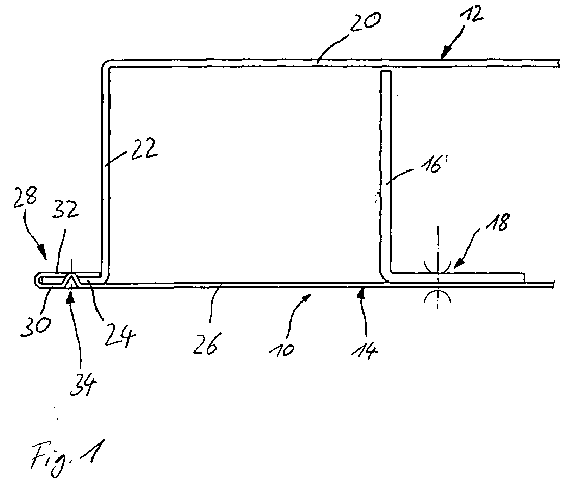
- FIG. 1 In the illustration of Figure 1 is a left half of an inventive Wiring duct 10 shown, wherein a sectional view, perpendicular to a longitudinal axis of the cable trunking, selected has been.
- the cable trunking consists of a top part 12 and a lower part 14 and one attached to the lower part 14 Partition 16.
- the partition 16 is L-shaped and lies with one of its legs flat on a bottom wall of the lower part 14 at.
- the partition wall 16 and the lower part 14 are by means of multiple spot welds 18 interconnected.
- a second leg of the Partition 16 is at right angles to the bottom wall of the lower part 14th arranged and extends into an interior of the trunking channel, the enclosed by the lower part 14 and the upper part 12 becomes.
- the upper part 12 has a U-like cross section with a cover 20th and two side walls 22, wherein in the illustration the only one Figure only one side wall 22 is shown. Starting from the Side wall 22 is a holding strip 24 approximately at right angles and from the interior of the trunking channel 10 is bent.
- the lower part 14 has a flat bottom wall 26, which are assembled in the State of the cable trunking 10 perpendicular to the Side walls 22 is arranged.
- a longitudinal edge of the bottom wall 14 is formed by a pocket 28 having a longitudinal direction Pocket bottom has.
- the retaining strip 24 of the upper part 12 is inserted.
- One in the presentation of the only one Figure lower pocket leg 30 is lying flat on an underside of the holding strip 24 and in the single figure upper pocket legs 32 lies flat against an upper side of the retaining strip 24.
- To secure the retaining strip 24 securely in the pocket 28 is in the lower pocket legs 30 introduced a granular depression 34.
- the granular depression 34 goes from one Surface of the lower pocket leg 30, which the retaining strip 24 is turned away.
- the granular depression 34 extends so far in the direction of the holding strip 24 and through it, that the upper pocket leg 34 is also mitverformt.
- the representation of the granular depression 34 in the figure is merely schematic and is intended to illustrate that the granular depression completely by the material thickness of the Haltestsammlungs 24 extends therethrough.
- the resulting Material displacement is also the upper pocket legs 32nd mitverformt. It is provided, neither the lower pocket legs 30, the retaining strip 24 still the upper pocket legs 32nd pre-drill at the point provided for the granular depression 34, Rather, should by the granular depression 34 a plastic material deformation done by means of then the retaining strips 34 is securely held in the bag 28.
- a manufacturing technology although more complex but also reliable Fixation of the retaining strip could also be achieved by the retaining strip 34 has a bore or a recess, into which the granular depression 34 then expand can. This can be advantageous, for example, if the upper part 20 made of particularly tough, poorly deformable material or for example made of plastic.
- the granular depressions 34 are by means of a roller placed on its circumference several, evenly spaced having spaced grains.
- the area of the opposite Roller, on which the upper pocket leg 32 rests, is flat, so that the cable guide channel 10 in the region of the upper pocket leg 32 remains almost flat. They are only weak impressions to recognize the upper pocket leg 32 in the areas in which by introducing the granular depression 34 material was displaced.
- the two rolls for introducing the grain-like Recesses 34 can be used as the last rolls of a profiling unit be arranged.
- the retaining strip 24 thus reliably against slipping out of the bag 28 in the direction of the interior of the trunking channel 10 to secured. It can also be seen that one in the figure below Surface of the bottom wall 26, which is the lower boundary of the cable trunking 10, is even, so that the wiring channel 10 with the bottom wall 26 flat on a flat surface can rest.
- FIG. 2 is a left half of an inventive Wiring duct 110 shown, wherein a front view, Seen along a longitudinal axis of the cable trunking selected has been.
- the cable trunking consists of an upper part 112 and a lower part 114 and a partition wall attached to the lower part 114 116.
- the partition wall 116 is L-shaped and lies with one of its legs flat on a bottom wall of the lower part 114th on.
- the partition wall 116 and the lower part 114 are by means of several Spot welds 118 connected together.
- a second leg the partition 116 is at right angles to the bottom wall of the base 114 arranged and extends into an interior of the cable trunking, the enclosed by the lower part 114 and the upper part 112 becomes.
- the upper part 112 has a U-like cross-section with a lid 120 and two side walls 122, wherein in the illustration of FIG. 2 only one side wall 122 is shown. Starting from the side wall 122 is a holding strip 124 approximately at right angles and from the interior bent the wiring channel 110.
- the lower part 114 has a flat bottom wall 126, which is assembled in the State of the cable management channel 110 perpendicular to the side walls 122 is arranged.
- a longitudinal edge of the bottom wall 114 is formed by a pocket 128 having a longitudinal direction having running pocket bottom.
- the retaining strip 124 of the upper 112 inserted.
- One in the presentation of the Fig. 1 lower pocket leg 130 is lying flat on an underside of the holding strip 124 and a in Fig. 1 upper pocket legs 132 lies flat against an upper side of the retaining strip 124.
- Around To secure the retaining strip 124 securely in the pocket 128 are the retaining strips 124 and the pocket legs 130, 132 interlocked and each have a V-like in the longitudinal direction Shape up. Through this entanglement of upper part 112 and lower part 114 is the retaining strip 124 against slipping out of the pocket 128 in the direction of the interior of the wiring channel 110 to secured.
- the retaining strip 124 and the pocket legs 130, 132 respectively a longitudinal bending axis to its V-like shape bent, can be the entanglement of upper part 112 and lower part 114 during the manufacturing process of the cable trunking 110 on a roll bending machine.
- This will be the Production of the cable routing channel 110 over conventional Cable ducts without entanglement of upper part 112 and lower part 114 is not hampered by the improved grip of the retaining strip 124 in the bag 128 but can the material thickness of the upper part 112 and / or lower part 114 can be significantly reduced, without at rough handling slipping out of the retaining strip 124 from the Bag 128 is to be feared.
- FIG. 3 shows the training the retaining strip 124 and its arrangement in the pocket 128.
- a first portion 134 of the retaining strip 124 is a first portion 134 of the retaining strip 124 about a longitudinal bending axis of Interior of the trunking channel 110 bent away.
- the first paragraph 134 of the retaining strip 124 takes to the side wall 122 a Angle of about 80 degrees.
- the first section 134 is followed by a second section 136, the opposite to the first portion 134 by an angle of about 20 Degree is bent about a longitudinal bending axis.
- the second portion 136 makes an angle from about 100 degrees.
- the retaining strip 124 receives through the sections 134 and 136 already recognizable in Fig. 1 V-like shape.
- first portion 138 of the first Pocket leg 130 Starting from the bottom wall 126 is a first portion 138 of the first Pocket leg 130 to the interior of the cable trunking Bent down 110, so that the first portion 138 of the first pocket leg 130 to the side wall 123 an angle of about 80 Degree takes. As can be seen, the first portion 138 of the first pocket leg 130 flat on the portion 134 of the retaining strip 124 on.
- the first section 138 is followed by a second section 140 of the first pocket leg 130, which is opposite the first section 138 about a longitudinally extending bending axis by about 20 Degree, away from the interior of the wiring channel 110, bent is.
- the second portion 140 thereby enters the sidewall Angle of about 100 degrees.
- the pocket bottom connects the second portion 140 of the lower pocket leg 130 with a second portion 142 of the second pocket leg 132.
- the second Section 142 of the second pocket leg 132 is parallel to the second Section 140 of the first pocket leg 130 is arranged.
- the second section 142 is followed by a first section 144 of FIG upper pocket leg 132, which is parallel to the first section 138th of the lower pocket leg 130 is arranged.
- the lower pocket leg 130, the retaining strip 124 and the upper pocket legs 132 in the area their sections 134, 136, 138, 140, 142 and 144 flat against each other.
- the retaining strip 124 is thereby against slipping out of the pocket 128 in the direction of the interior the wiring channel 110 to secured.
- a lying in the Fig. 2 bottom surface of the bottom wall 126th represents the lower limit of the wiring channel 110, so that the bottom wall 126 lie flat on a flat surface could.
- inventions shown in Figures 1 to 3 can be also combine to the effect that in addition to a V-shaped Deformation of retaining strip and pocket additionally granular Wells are introduced.
Landscapes
- Engineering & Computer Science (AREA)
- Architecture (AREA)
- Civil Engineering (AREA)
- Structural Engineering (AREA)
- Mechanical Engineering (AREA)
- Details Of Indoor Wiring (AREA)
- Electric Cable Arrangement Between Relatively Moving Parts (AREA)
- Light Guides In General And Applications Therefor (AREA)
- Manufacturing Of Electric Cables (AREA)
- Electric Cable Installation (AREA)
- Installation Of Indoor Wiring (AREA)
- Laying Of Electric Cables Or Lines Outside (AREA)
- Insulated Conductors (AREA)
Abstract
Description
- Fig. 1
- eine abschnittsweise Schnittansicht eines erfindungsgemäßen Leitungsführungskanals gemäß einer ersten Ausführungsform,
- Fig. 2
- eine abschnittsweise Vorderansicht eines erfindungsgemäßen Leitungsführungskanals gemäß einer zweiten Ausführungsform und
- Fig. 3
- eine ausschnittweise Vergrößerung des Leitungsführungskanals der Fig. 2.
Claims (12)
- Leitungsführungskanal mit einem Oberteil (12; 112) und einem Unterteil (14; 114), wobei das Oberteil (12; 112) oder das Unterteil (14; 114) mit einem sich an eine Längskante anschließenden Haltestreifen (24; 124) versehen ist, der wenigstens abschnittsweise in einer am Unterteil (14; 114) beziehungsweise Oberteil (12; 112) gebildeten Tasche (28; 128) mit einem in Längsrichtung verlaufenden Taschengrund angeordnet ist, wobei die Tasche (28; 128) den in ihr angeordneten Haltestreifen (24; 124) mit zwei Taschenschenkeln (30, 32; 130, 132) umgreift und die Taschenschenkel (30, 32; 130, 132) und der Haltestreifen (24; 124) wenigstens abschnittsweise aneinander anliegen, dadurch gekennzeichnet, dass wenigstens einer der Taschenschenkel (30, 32; 130, 132) und der Haltestreifen (24; 124) formschlüssig aneinander fixiert sind.
- Leitungsführungskanal nach Anspruch 1, dadurch gekennzeichnet, dass in wenigstens einen der Taschenschenkel (30, 32) mehrere, von einer dem Haltestreifen (24) abgewandten Oberfläche ausgehende körnerschlagartige Vertiefungen (34) eingebracht sind, um den Haltestreifen (24) und den wenigstens einen Taschenschenkel (30, 32) relativ zueinander zu fixieren.
- Leitungsführungskanal nach Anspruch 1 oder 2, dadurch gekennzeichnet, dass die Oberfläche des Taschenschenkels (30, 32) , von der die körnerschlagartigen Vertiefungen (34) ausgehen, auf einer dem Oberteil (12) abgewandten Unterseite des Unterteils (14) liegt.
- Leitungsführungskanal nach wenigstens einem der vorstehenden Ansprüche, dadurch gekennzeichnet, dass mehrere körnerschlagartige Vertiefungen (34) parallel zu einer Längsrichtung des Leitungsführungskanals gesehen in regelmäßigem Abstand zueinander angeordnet sind.
- Leitungsführungskanal nach wenigstens einem der vorstehenden Ansprüche, dadurch gekennzeichnet, dass mittels der körnerschlagartigen Vertiefung (34) eine gemeinsame Verformung beider Taschenschenkel (30, 32) und des Haltestreifens (24) bewirkt ist.
- Leitungsführungskanal nach wenigstens einem der vorstehenden Ansprüche, dadurch gekennzeichnet, dass Oberteil (12; 112) und Unterteil (14; 114) als Blechbiegeteil ausgebildet sind.
- Leitungsführungskanal nach wenigstens einem der vorstehenden Ansprüche, dadurch gekennzeichnet, dass der in der Tasche (128) angeordnete Haltestreifen (124) und die an dem Haltestreifen (124) anliegenden Taschenschenkel (130, 132) jeweils wenigstens zwei in einem Winkel zueinander angeordnete Abschnitte (134, 136, 138, 140, 142, 144) aufweisen.
- Leitungsführungskanal nach Anspruch 7, dadurch gekennzeichnet, dass die zwei in einem Winkel zueinander angeordneten Abschnitte (134, 136, 138, 140, 142, 144) des Haltestreifens (124) und der Taschenschenkel (130, 132) jeweils um eine in Längsrichtung verlaufende Biegeachse abgewinkelt sind.
- Leitungsführungskanal nach Anspruch 8, dadurch gekennzeichnet, dass der Haltestreifen (124) und die Taschenschenkel (130, 132) in Längsrichtung gesehen V-artig gebogen sind.
- Leitungsführungskanal nach wenigstens einem der vorstehenden Ansprüche 7 bis 9, dadurch gekennzeichnet, dass der Winkel zwischen 15 Grad und 90 Grad, insbesondere im Bereich von 20 Grad liegt.
- Leitungsführungskanal nach wenigstens einem der vorstehenden Ansprüche, dadurch gekennzeichnet, dass der Haltestreifen (124) ausgehend von einer Seitenwand (122) des Oberteils (112) oder Unterteils (14; 114) abgewinkelt ist, wobei ein sich an die Seitenwand (122) anschließender erster Abschnitt (134) des Haltestreifens (124) in Längsrichtung gesehen zu der Seitenwand (122) einen Winkel von weniger als 90 Grad einnimmt und ein sich insbesondere an den ersten Abschnitt (134) anschließender zweiter Abschnitt (136) des Haltestreifens (124) zu der Seitenwand (122) einen Winkel von mehr als 90 Grad einnimmt.
- Leitungsführungskanal nach Anspruch 11, dadurch gekennzeichnet, dass die Tasche (128) ausgehend von einer im wesentlichen senkrecht zur Seitenwand (122) angeordneten Bodenwand (126) des Unterteils (14; 114) oder Oberteils (112) gebildet ist und ein sich an die Bodenwand (126) anschließender erster Abschnitt (138) eines ersten Taschenschenkels (130) zur Seitenwand (122) einen Winkel von weniger als 90 Grad einnimmt.
Priority Applications (1)
| Application Number | Priority Date | Filing Date | Title |
|---|---|---|---|
| PL04010736T PL1482613T3 (pl) | 2003-05-13 | 2004-05-06 | Kanał prowadzący do przewodów |
Applications Claiming Priority (4)
| Application Number | Priority Date | Filing Date | Title |
|---|---|---|---|
| DE20307765U DE20307765U1 (de) | 2003-05-13 | 2003-05-13 | Leitungsführungskanal |
| DE20307765U | 2003-05-13 | ||
| DE20317387U DE20317387U1 (de) | 2003-11-05 | 2003-11-05 | Leitungsführungskanal |
| DE20317387U | 2003-11-05 |
Publications (3)
| Publication Number | Publication Date |
|---|---|
| EP1482613A2 true EP1482613A2 (de) | 2004-12-01 |
| EP1482613A3 EP1482613A3 (de) | 2006-02-08 |
| EP1482613B1 EP1482613B1 (de) | 2008-08-13 |
Family
ID=33132876
Family Applications (1)
| Application Number | Title | Priority Date | Filing Date |
|---|---|---|---|
| EP04010736A Expired - Lifetime EP1482613B1 (de) | 2003-05-13 | 2004-05-06 | Leitungsführungskanal |
Country Status (5)
| Country | Link |
|---|---|
| EP (1) | EP1482613B1 (de) |
| AT (1) | ATE405014T1 (de) |
| DE (1) | DE502004007816D1 (de) |
| ES (1) | ES2311768T3 (de) |
| PL (1) | PL1482613T3 (de) |
Cited By (2)
| Publication number | Priority date | Publication date | Assignee | Title |
|---|---|---|---|---|
| WO2009074772A3 (en) * | 2007-12-13 | 2010-06-17 | Novar Ed & S Limited | Cable ducting |
| EP4344641A1 (de) * | 2022-09-29 | 2024-04-03 | Koninklijke Philips N.V. | Kabelführung in beweglichen medizinischen geräten |
Family Cites Families (5)
| Publication number | Priority date | Publication date | Assignee | Title |
|---|---|---|---|---|
| DE2347501A1 (de) * | 1973-09-21 | 1975-04-03 | Hermann Wilden | Kanal fuer unterflur-installationsleitungen |
| DE2352913A1 (de) * | 1973-10-22 | 1975-04-30 | Hermann Wilden | Kanal fuer unterflur-installationsleitungen |
| DE7721965U1 (de) * | 1977-07-13 | 1977-10-13 | Fa. Albert Ackermann, 5270 Gummersbach | Unterflurkanal mit AusgleichstUck |
| GB2161330A (en) * | 1984-07-02 | 1986-01-08 | Bicc Plc | An improved cable tray |
| US5125199A (en) * | 1989-11-13 | 1992-06-30 | Square D Company | Floor duct with integral interlock |
-
2004
- 2004-05-06 ES ES04010736T patent/ES2311768T3/es not_active Expired - Lifetime
- 2004-05-06 EP EP04010736A patent/EP1482613B1/de not_active Expired - Lifetime
- 2004-05-06 PL PL04010736T patent/PL1482613T3/pl unknown
- 2004-05-06 DE DE502004007816T patent/DE502004007816D1/de not_active Expired - Lifetime
- 2004-05-06 AT AT04010736T patent/ATE405014T1/de active
Cited By (3)
| Publication number | Priority date | Publication date | Assignee | Title |
|---|---|---|---|---|
| WO2009074772A3 (en) * | 2007-12-13 | 2010-06-17 | Novar Ed & S Limited | Cable ducting |
| EP4344641A1 (de) * | 2022-09-29 | 2024-04-03 | Koninklijke Philips N.V. | Kabelführung in beweglichen medizinischen geräten |
| WO2024068494A1 (en) * | 2022-09-29 | 2024-04-04 | Koninklijke Philips N.V. | Cable guidance in movable medical appliances |
Also Published As
| Publication number | Publication date |
|---|---|
| PL1482613T3 (pl) | 2009-04-30 |
| ES2311768T3 (es) | 2009-02-16 |
| EP1482613A3 (de) | 2006-02-08 |
| DE502004007816D1 (de) | 2008-09-25 |
| EP1482613B1 (de) | 2008-08-13 |
| ATE405014T1 (de) | 2008-08-15 |
Similar Documents
| Publication | Publication Date | Title |
|---|---|---|
| EP1748215B1 (de) | Bremsbelagträgerplatte | |
| EP2084339B1 (de) | Abdeckrost | |
| EP1068053B1 (de) | Vorrichtung zum entfernen von ausbrechteilen aus einem werkstoffbogen oder dergleichen | |
| DE102016107710B4 (de) | Abdeckungsbaugruppe für einen Einfüllanschluss eines Fahrzeugs | |
| DE60032028T2 (de) | Verbindungsstruktur eines Kanals | |
| DE102011086373A1 (de) | Steckzunge | |
| DE10042087A1 (de) | Verstärkungssystem für einen Kraftfahrzeugkotflügel und eine Klammer dafür | |
| WO2011009569A1 (de) | Weinbergpfahl | |
| DE102022128913B3 (de) | Vorrichtung zum Kühlen einer Batterie, Verfahren zum Herstellen der Vorrichtung, Batterie und Fahrzeug umfassend die Vorrichtung | |
| DE60026266T2 (de) | Zusammengesetztes Bauteil , insbesondere Frontplatte eines Fahrzeugs | |
| EP1482613B1 (de) | Leitungsführungskanal | |
| EP0948108A2 (de) | Wellrohr mit Fuss | |
| DE19645517A1 (de) | Türblatt, insbesondere für Aufzugstüren | |
| DE60116740T2 (de) | Strangpresswerkzeug | |
| EP0989277A3 (de) | Tür, insbesondere Brandschutztür | |
| DE20307765U1 (de) | Leitungsführungskanal | |
| EP1476644A1 (de) | Verfahren zum herstellen einer auf das ende eines kraftfahrzeug-auspuffrohres aufsetzbaren blende und eine nach dem verfahren hergestellte blende | |
| DE112022003065T5 (de) | Metalldraht und Gummiverbundkörper | |
| DE202021102161U1 (de) | Aus Metall hergestellte Kabelrinnenkomponente, insbesondere Kabelrinne oder Kabelrinnendeckel | |
| EP2775086A1 (de) | Kanalträger | |
| DE3705722C2 (de) | ||
| DE8903586U1 (de) | Metallschublade | |
| EP2136014B1 (de) | Kantenschutzprofil | |
| DE3026925C2 (de) | Luftbereiftes Rad für Schwerlastfahrzeuge | |
| DE20317387U1 (de) | Leitungsführungskanal |
Legal Events
| Date | Code | Title | Description |
|---|---|---|---|
| PUAI | Public reference made under article 153(3) epc to a published international application that has entered the european phase |
Free format text: ORIGINAL CODE: 0009012 |
|
| AK | Designated contracting states |
Kind code of ref document: A2 Designated state(s): AT BE BG CH CY CZ DE DK EE ES FI FR GB GR HU IE IT LI LU MC NL PL PT RO SE SI SK TR |
|
| AX | Request for extension of the european patent |
Extension state: AL HR LT LV MK |
|
| PUAL | Search report despatched |
Free format text: ORIGINAL CODE: 0009013 |
|
| AK | Designated contracting states |
Kind code of ref document: A3 Designated state(s): AT BE BG CH CY CZ DE DK EE ES FI FR GB GR HU IE IT LI LU MC NL PL PT RO SE SI SK TR |
|
| AX | Request for extension of the european patent |
Extension state: AL HR LT LV MK |
|
| 17P | Request for examination filed |
Effective date: 20060720 |
|
| AKX | Designation fees paid |
Designated state(s): AT BE BG CH CY CZ DE DK EE ES FI FR GB GR HU IE IT LI LU MC NL PL PT RO SE SI SK TR |
|
| RAP1 | Party data changed (applicant data changed or rights of an application transferred) |
Owner name: OBO BETTERMANN GMBH & CO. KG |
|
| RIN1 | Information on inventor provided before grant (corrected) |
Inventor name: DOEBBELER, PETER Inventor name: RASCHKE JOERG |
|
| GRAP | Despatch of communication of intention to grant a patent |
Free format text: ORIGINAL CODE: EPIDOSNIGR1 |
|
| GRAS | Grant fee paid |
Free format text: ORIGINAL CODE: EPIDOSNIGR3 |
|
| GRAA | (expected) grant |
Free format text: ORIGINAL CODE: 0009210 |
|
| AK | Designated contracting states |
Kind code of ref document: B1 Designated state(s): AT BE BG CH CY CZ DE DK EE ES FI FR GB GR HU IE IT LI LU MC NL PL PT RO SE SI SK TR |
|
| REG | Reference to a national code |
Ref country code: GB Ref legal event code: FG4D Free format text: NOT ENGLISH |
|
| REG | Reference to a national code |
Ref country code: CH Ref legal event code: EP |
|
| REG | Reference to a national code |
Ref country code: IE Ref legal event code: FG4D Free format text: LANGUAGE OF EP DOCUMENT: GERMAN |
|
| REF | Corresponds to: |
Ref document number: 502004007816 Country of ref document: DE Date of ref document: 20080925 Kind code of ref document: P |
|
| REG | Reference to a national code |
Ref country code: RO Ref legal event code: EPE |
|
| REG | Reference to a national code |
Ref country code: ES Ref legal event code: FG2A Ref document number: 2311768 Country of ref document: ES Kind code of ref document: T3 |
|
| PG25 | Lapsed in a contracting state [announced via postgrant information from national office to epo] |
Ref country code: FI Free format text: LAPSE BECAUSE OF FAILURE TO SUBMIT A TRANSLATION OF THE DESCRIPTION OR TO PAY THE FEE WITHIN THE PRESCRIBED TIME-LIMIT Effective date: 20080813 Ref country code: SI Free format text: LAPSE BECAUSE OF FAILURE TO SUBMIT A TRANSLATION OF THE DESCRIPTION OR TO PAY THE FEE WITHIN THE PRESCRIBED TIME-LIMIT Effective date: 20080813 |
|
| REG | Reference to a national code |
Ref country code: IE Ref legal event code: FD4D |
|
| PG25 | Lapsed in a contracting state [announced via postgrant information from national office to epo] |
Ref country code: DK Free format text: LAPSE BECAUSE OF FAILURE TO SUBMIT A TRANSLATION OF THE DESCRIPTION OR TO PAY THE FEE WITHIN THE PRESCRIBED TIME-LIMIT Effective date: 20080813 Ref country code: IE Free format text: LAPSE BECAUSE OF FAILURE TO SUBMIT A TRANSLATION OF THE DESCRIPTION OR TO PAY THE FEE WITHIN THE PRESCRIBED TIME-LIMIT Effective date: 20080813 Ref country code: BG Free format text: LAPSE BECAUSE OF FAILURE TO SUBMIT A TRANSLATION OF THE DESCRIPTION OR TO PAY THE FEE WITHIN THE PRESCRIBED TIME-LIMIT Effective date: 20081113 |
|
| REG | Reference to a national code |
Ref country code: PL Ref legal event code: T3 |
|
| PG25 | Lapsed in a contracting state [announced via postgrant information from national office to epo] |
Ref country code: PT Free format text: LAPSE BECAUSE OF FAILURE TO SUBMIT A TRANSLATION OF THE DESCRIPTION OR TO PAY THE FEE WITHIN THE PRESCRIBED TIME-LIMIT Effective date: 20090113 Ref country code: SK Free format text: LAPSE BECAUSE OF FAILURE TO SUBMIT A TRANSLATION OF THE DESCRIPTION OR TO PAY THE FEE WITHIN THE PRESCRIBED TIME-LIMIT Effective date: 20080813 Ref country code: CZ Free format text: LAPSE BECAUSE OF FAILURE TO SUBMIT A TRANSLATION OF THE DESCRIPTION OR TO PAY THE FEE WITHIN THE PRESCRIBED TIME-LIMIT Effective date: 20080813 |
|
| PLBE | No opposition filed within time limit |
Free format text: ORIGINAL CODE: 0009261 |
|
| STAA | Information on the status of an ep patent application or granted ep patent |
Free format text: STATUS: NO OPPOSITION FILED WITHIN TIME LIMIT |
|
| 26N | No opposition filed |
Effective date: 20090514 |
|
| PG25 | Lapsed in a contracting state [announced via postgrant information from national office to epo] |
Ref country code: EE Free format text: LAPSE BECAUSE OF FAILURE TO SUBMIT A TRANSLATION OF THE DESCRIPTION OR TO PAY THE FEE WITHIN THE PRESCRIBED TIME-LIMIT Effective date: 20080813 |
|
| PG25 | Lapsed in a contracting state [announced via postgrant information from national office to epo] |
Ref country code: MC Free format text: LAPSE BECAUSE OF NON-PAYMENT OF DUE FEES Effective date: 20090531 |
|
| REG | Reference to a national code |
Ref country code: CH Ref legal event code: PL |
|
| GBPC | Gb: european patent ceased through non-payment of renewal fee |
Effective date: 20090506 |
|
| PG25 | Lapsed in a contracting state [announced via postgrant information from national office to epo] |
Ref country code: CH Free format text: LAPSE BECAUSE OF NON-PAYMENT OF DUE FEES Effective date: 20090531 Ref country code: SE Free format text: LAPSE BECAUSE OF FAILURE TO SUBMIT A TRANSLATION OF THE DESCRIPTION OR TO PAY THE FEE WITHIN THE PRESCRIBED TIME-LIMIT Effective date: 20081113 Ref country code: LI Free format text: LAPSE BECAUSE OF NON-PAYMENT OF DUE FEES Effective date: 20090531 |
|
| REG | Reference to a national code |
Ref country code: FR Ref legal event code: ST Effective date: 20100129 |
|
| PG25 | Lapsed in a contracting state [announced via postgrant information from national office to epo] |
Ref country code: FR Free format text: LAPSE BECAUSE OF NON-PAYMENT OF DUE FEES Effective date: 20090602 Ref country code: RO Free format text: LAPSE BECAUSE OF NON-PAYMENT OF DUE FEES Effective date: 20080813 |
|
| PG25 | Lapsed in a contracting state [announced via postgrant information from national office to epo] |
Ref country code: GB Free format text: LAPSE BECAUSE OF NON-PAYMENT OF DUE FEES Effective date: 20090506 |
|
| PG25 | Lapsed in a contracting state [announced via postgrant information from national office to epo] |
Ref country code: GR Free format text: LAPSE BECAUSE OF FAILURE TO SUBMIT A TRANSLATION OF THE DESCRIPTION OR TO PAY THE FEE WITHIN THE PRESCRIBED TIME-LIMIT Effective date: 20081114 |
|
| REG | Reference to a national code |
Ref country code: PL Ref legal event code: LAPE |
|
| PG25 | Lapsed in a contracting state [announced via postgrant information from national office to epo] |
Ref country code: IT Free format text: LAPSE BECAUSE OF NON-PAYMENT OF DUE FEES Effective date: 20090506 |
|
| PG25 | Lapsed in a contracting state [announced via postgrant information from national office to epo] |
Ref country code: LU Free format text: LAPSE BECAUSE OF NON-PAYMENT OF DUE FEES Effective date: 20090506 |
|
| PG25 | Lapsed in a contracting state [announced via postgrant information from national office to epo] |
Ref country code: PL Free format text: LAPSE BECAUSE OF NON-PAYMENT OF DUE FEES Effective date: 20090506 |
|
| PG25 | Lapsed in a contracting state [announced via postgrant information from national office to epo] |
Ref country code: HU Free format text: LAPSE BECAUSE OF FAILURE TO SUBMIT A TRANSLATION OF THE DESCRIPTION OR TO PAY THE FEE WITHIN THE PRESCRIBED TIME-LIMIT Effective date: 20090214 |
|
| PG25 | Lapsed in a contracting state [announced via postgrant information from national office to epo] |
Ref country code: CY Free format text: LAPSE BECAUSE OF FAILURE TO SUBMIT A TRANSLATION OF THE DESCRIPTION OR TO PAY THE FEE WITHIN THE PRESCRIBED TIME-LIMIT Effective date: 20080813 |
|
| PGFP | Annual fee paid to national office [announced via postgrant information from national office to epo] |
Ref country code: ES Payment date: 20120525 Year of fee payment: 9 |
|
| PGFP | Annual fee paid to national office [announced via postgrant information from national office to epo] |
Ref country code: AT Payment date: 20120521 Year of fee payment: 9 |
|
| PGFP | Annual fee paid to national office [announced via postgrant information from national office to epo] |
Ref country code: DE Payment date: 20130524 Year of fee payment: 10 |
|
| PGFP | Annual fee paid to national office [announced via postgrant information from national office to epo] |
Ref country code: NL Payment date: 20130523 Year of fee payment: 10 Ref country code: BE Payment date: 20130521 Year of fee payment: 10 |
|
| PG25 | Lapsed in a contracting state [announced via postgrant information from national office to epo] |
Ref country code: TR Free format text: LAPSE BECAUSE OF FAILURE TO SUBMIT A TRANSLATION OF THE DESCRIPTION OR TO PAY THE FEE WITHIN THE PRESCRIBED TIME-LIMIT Effective date: 20080813 |
|
| REG | Reference to a national code |
Ref country code: DE Ref legal event code: R119 Ref document number: 502004007816 Country of ref document: DE |
|
| REG | Reference to a national code |
Ref country code: NL Ref legal event code: V1 Effective date: 20141201 |
|
| REG | Reference to a national code |
Ref country code: AT Ref legal event code: MM01 Ref document number: 405014 Country of ref document: AT Kind code of ref document: T Effective date: 20140506 |
|
| REG | Reference to a national code |
Ref country code: DE Ref legal event code: R119 Ref document number: 502004007816 Country of ref document: DE Effective date: 20141202 |
|
| PG25 | Lapsed in a contracting state [announced via postgrant information from national office to epo] |
Ref country code: NL Free format text: LAPSE BECAUSE OF NON-PAYMENT OF DUE FEES Effective date: 20141201 Ref country code: AT Free format text: LAPSE BECAUSE OF NON-PAYMENT OF DUE FEES Effective date: 20140506 |
|
| PG25 | Lapsed in a contracting state [announced via postgrant information from national office to epo] |
Ref country code: DE Free format text: LAPSE BECAUSE OF NON-PAYMENT OF DUE FEES Effective date: 20141202 |
|
| REG | Reference to a national code |
Ref country code: ES Ref legal event code: FD2A Effective date: 20150626 |
|
| PG25 | Lapsed in a contracting state [announced via postgrant information from national office to epo] |
Ref country code: ES Free format text: LAPSE BECAUSE OF NON-PAYMENT OF DUE FEES Effective date: 20140507 |
|
| PG25 | Lapsed in a contracting state [announced via postgrant information from national office to epo] |
Ref country code: BE Free format text: LAPSE BECAUSE OF NON-PAYMENT OF DUE FEES Effective date: 20140531 |