EP1482599A2 - Connector - Google Patents
Connector Download PDFInfo
- Publication number
- EP1482599A2 EP1482599A2 EP04012754A EP04012754A EP1482599A2 EP 1482599 A2 EP1482599 A2 EP 1482599A2 EP 04012754 A EP04012754 A EP 04012754A EP 04012754 A EP04012754 A EP 04012754A EP 1482599 A2 EP1482599 A2 EP 1482599A2
- Authority
- EP
- European Patent Office
- Prior art keywords
- receptacle
- plug
- pin contact
- shell
- receiving hole
- Prior art date
- Legal status (The legal status is an assumption and is not a legal conclusion. Google has not performed a legal analysis and makes no representation as to the accuracy of the status listed.)
- Withdrawn
Links
Images


Classifications
-
- H—ELECTRICITY
- H01—ELECTRIC ELEMENTS
- H01R—ELECTRICALLY-CONDUCTIVE CONNECTIONS; STRUCTURAL ASSOCIATIONS OF A PLURALITY OF MUTUALLY-INSULATED ELECTRICAL CONNECTING ELEMENTS; COUPLING DEVICES; CURRENT COLLECTORS
- H01R13/00—Details of coupling devices of the kinds covered by groups H01R12/70 or H01R24/00 - H01R33/00
- H01R13/64—Means for preventing incorrect coupling
- H01R13/642—Means for preventing incorrect coupling by position or shape of contact members
-
- H—ELECTRICITY
- H01—ELECTRIC ELEMENTS
- H01R—ELECTRICALLY-CONDUCTIVE CONNECTIONS; STRUCTURAL ASSOCIATIONS OF A PLURALITY OF MUTUALLY-INSULATED ELECTRICAL CONNECTING ELEMENTS; COUPLING DEVICES; CURRENT COLLECTORS
- H01R24/00—Two-part coupling devices, or either of their cooperating parts, characterised by their overall structure
- H01R24/38—Two-part coupling devices, or either of their cooperating parts, characterised by their overall structure having concentrically or coaxially arranged contacts
- H01R24/40—Two-part coupling devices, or either of their cooperating parts, characterised by their overall structure having concentrically or coaxially arranged contacts specially adapted for high frequency
- H01R24/52—Two-part coupling devices, or either of their cooperating parts, characterised by their overall structure having concentrically or coaxially arranged contacts specially adapted for high frequency mounted in or to a panel or structure
-
- H—ELECTRICITY
- H01—ELECTRIC ELEMENTS
- H01R—ELECTRICALLY-CONDUCTIVE CONNECTIONS; STRUCTURAL ASSOCIATIONS OF A PLURALITY OF MUTUALLY-INSULATED ELECTRICAL CONNECTING ELEMENTS; COUPLING DEVICES; CURRENT COLLECTORS
- H01R2103/00—Two poles
-
- H—ELECTRICITY
- H01—ELECTRIC ELEMENTS
- H01R—ELECTRICALLY-CONDUCTIVE CONNECTIONS; STRUCTURAL ASSOCIATIONS OF A PLURALITY OF MUTUALLY-INSULATED ELECTRICAL CONNECTING ELEMENTS; COUPLING DEVICES; CURRENT COLLECTORS
- H01R2201/00—Connectors or connections adapted for particular applications
- H01R2201/02—Connectors or connections adapted for particular applications for antennas
-
- H—ELECTRICITY
- H01—ELECTRIC ELEMENTS
- H01R—ELECTRICALLY-CONDUCTIVE CONNECTIONS; STRUCTURAL ASSOCIATIONS OF A PLURALITY OF MUTUALLY-INSULATED ELECTRICAL CONNECTING ELEMENTS; COUPLING DEVICES; CURRENT COLLECTORS
- H01R2201/00—Connectors or connections adapted for particular applications
- H01R2201/04—Connectors or connections adapted for particular applications for network, e.g. LAN connectors
Definitions
- the present invention relates to a connector. More specifically, it relates to a connector for use in a notebook-sized personal computer and connecting to an external antenna for wireless LAN(Local Area Network), for example.
- Portable electronic systems adopting the wireless LAN such as notebook-sized personal computers (hereinafter referred to as notebook-sized PCs) and Personal Digital Assistants (PDA) have been used at offices, homes, and the like.
- notebook-sized PCs notebook-sized personal computers
- PDA Personal Digital Assistants
- Such electronic systems allow users to connect to broadband routers from any places by wireless and to access the Internet freely.
- An electronic system as described above is provided with, for example, an internal antenna for transmitting and receiving electric waves inside a housing.
- the housing is provided with a coaxial connector having a switching function in order to further increase the receiving efficiency thereof. Accordingly, when it is difficult to transmit and receive electric waves through the internal antenna, the coaxial connector is connected to the external antenna to switch from the internal antenna to the external antenna. Therefore, electric waves can be transmitted and received through the external antenna.
- Wireless LAN like this is standardized under IEEE 802.11a by Institute of Electrical and Electronic Engineers (IEEE). More specifically, Federal communications commission (FCC) defines that manufacturers shall customize connectors for wireless LAN for electronic systems to transmit and receive electric waves in a frequency range around 5.2GHz used for high-speed wireless LAN. In other words, it is defined that connectors for antennas shall each have a maker-specific structure so as to prevent any external antennas of other manufacturers from being connected to the connectors.
- FCC Federal communications commission
- the connector has a plug connected to an external antenna and a receptacle formed with a plug-in opening in which the plug is to be plugged.
- the plug has the key provided in its distal end
- the receptacle has the key groove provided in the plug-in opening thereof.
- the key of the plug is fitted in the key groove of the receptacle, which makes it impossible to connect the other manufacturer's plug to the receptacle.
- the plug and receptacle can be reliably connected with each other by screwing the coupling cap nut that the plug holds in the external thread formed in the periphery of the receptacle.
- the connector when a coaxial cable is connected to the side face of the plug, i.e. when the connector is a so-called right angle connector (and also referred to as an L-shaped connector) in which the direction of the plug plugged in and the extending direction of the coaxial cable intersect at right angles, the posture of the plug is limited by the provision of the key and key groove when the plug is plugged. Accordingly, the connector may not be able to obtain good usability because the extending direction of the coaxial cable is also limited.
- FCC is not limited to the combination of the key and key groove as a maker-specific structure.
- an object of the invention is to provide a connector which does not allow any external antennas of other manufacturers to be connected to the receptacle and allows the plug to be readily connected to the receptacle.
- Fig. 1 is a perspective sectional view of a connector according to a first embodiment of the invention.
- the connector has a plug 1 connected to an antenna through a coaxial cable 10, and a rectangular parallelepiped receptacle 2 which the plug 1 is to be put in and removed from.
- the receptacle 2 is mounted on a side face of a notebook-sized PC (not shown), and the plug 1 is connected to an antenna for high-speed wireless LAN standardized under IEEE 802.11a.
- the connector can transmit and receive radio waves with an external antenna.
- the coaxial cable 10 includes: a core wire 10A as an inside conductor extending in its axial direction; an insulator 10B for covering the core wire 10A, which is formed from polyethylene or the like; a braided wire 10C as an outside conductor provided outside the insulator 10B and extending in its axial direction; and an insulator 10D for covering the braided wire 10C.
- Fig. 2A is a top view of the plug 1
- Fig. 2B is a longitudinal sectional view of the plug 1
- Fig. 2C is a bottom view of the plug 1.
- the plug 1 includes: a cylindrical shell 12 having an outer diameter d connected to the coaxial cable 10; a pin contact 11 connected to the core wire 10A of the coaxial cable 10; and an insulative pin contact holder 13 provided inside the shell 12 for keeping the pin contact 11 on the central axis of the shell 12.
- the shell 12 and pin contact 11 are disposed concentrically.
- the pin contact 11 has a columnar form with a small outer diameter on the side of a distal end thereof, and a columnar form with a large outer diameter on a proximal end side thereof. More specifically, a step is formed between the distal end and proximal end of the pin contact 11.
- the pin contact 11 is shaped into a conical form.
- the pin contact 11 has an arc-shape groove formed on the proximal end side, and the core wire 10A of the coaxial cable 10 is fixed in the groove by solder.
- a through-hole into which the pin contact 11 is inserted is formed in the pin contact holder 13.
- the pin contact holder 13 has a columnar first protrusion 13A formed on its distal end surface.
- the shell 12 has an annular groove portion 1B formed in the outer peripheral surface thereof on the side of the distal end of the shell.
- the shell 12 has notches formed in positions opposed to each other nearly in the middle of the outer peripheral surface of the shell 12.
- One of the notches is a protruding piece 1C protruding toward the inside of the shell, and the other is a bendable bending piece 1D. Therefore, the pin contact holder 13 is inserted into the shell 12 from the proximal end side of the shell until the holder 13 abuts the protruding piece 1C. Then by bending the bending piece 1D inwardly, the bending piece 1D engages the pin contact holder 13. The pin contact holder 13 is thus held by the shell 12.
- the coaxial cable 10 is inserted into the shell 12 on the proximal end side of the shell.
- the insulator 10D is peeled off so that the braided wire 10C is exposed.
- the braided wire 10C and the insulator 10D are peeled off and thus the core wire 10A is exposed.
- the exposed portion of the core wire 10A is fixed on the proximal end side of the pin contact 11. Further, an insulative tube ferrule 15 is mounted between the exposed portions of the braided wire 10C and insulator 10B. The exposed portion of the braided wire 20C is clamped on the proximal end side of the shell 12. Therefore, the exposed portion of the braided wire 10C is pinched on the proximal end side of the cylindrical shell 12 and electrically connected to the shell 12.
- the connecting portion of the plug 1 and coaxial cable 10 is covered by a boot 10E as an insulating protective cover. Therefore, the plug 1 is put in and removed from the receptacle 2 by grasping the boot 10E.
- Fig. 2D is a transverse sectional view of the receptacle 2
- Fig. 2E is a longitudinal sectional view of the receptacle 2.
- the receptacle 2 includes: a first receptacle housing 21 having a shell-receiving hole 2B into which the shell 12 of the plug 1 is inserted; and a second receptacle housing 26 which is provided inside the shell-receiving hole 2B and has a pin contact-receiving hole 2A into which the pin contact 11 is inserted.
- the shell-receiving hole 2B of the first receptacle housing 21 has an inner diameter D which is slightly larger than the outer diameter d of the shell 12.
- An annular groove is formed between the shell-receiving hole 2B and the pin contact-receiving portion 22.
- the annular groove and the pin contact-receiving hole 2A are formed on concentric circles.
- a first ground shell 24 extending along its axial direction is provided in the inner surface of the shell-receiving hole 2B.
- the second receptacle housing 26 includes : a cylindrical second ground shell 25 extending along the axial direction of the shell-receiving hole 2B; and the pin contact-receiving portion 22 provided in the distal end of the second ground shell 25 and having the pin contact-receiving hole 2A.
- a first reentrant 21A in which the first protrusion 13A is to be fitted is formed in the distal end surface of the pin contact-receiving portion 22 .
- the pin contact-receiving hole 2A is formed in the center of the first reentrant 21A.
- Elastically-deformable second pressing pieces 25C, 25D which protrude outwardly are provided on the second ground shell 25.
- a fixed contact 23B extending along the axial direction of the second ground shell 25, and an elastically-deformable and movable contact 23A urged toward the fixed contact 23B.
- Fig. 3 is an exploded perspective view of the first ground shell 24, second ground shell 25, fixed contact 23B, and movable contact 23A, which constitute the receptacle 2.
- the fixed contact 233 is shaped like a plate, and includes a proximal end portion 235 fixed on a printed wiring board (not shown) by solder or the like and a distal end portion 234 which a bending piece 233 of the movable contact to be described later abuts.
- the movable contact 23A is formed from a leaf spring, and includes a proximal end portion 232 fixed on the printed wiring board (net shown) by solder or the like and a distal end portion 231 curved so that it becomes closer to the fixed contact 23B towards the distal end thereof.
- the distal end portion 231 of the movable contact 23A is located on the route which the pin contact 11 is passed through. A portion near the distal end of the distal end portion 231 is bent toward the fixed contact 23B and therefore it is a bending piece 233 abutting the fixed contact 23B.
- the second ground shell 25 is conductive and has a cylindrical form on the side of its distal end portion and a U-shaped form in cross section on the proximal end side thereof.
- the second pressing pieces 25C, 25D are elastically deformable and extending toward the outside of the second ground shell 25.
- the second ground shell 25 is fixed to the printed wiring board (not shown) by solder or the like on the proximal end side and grounded.
- the above-described first ground shell 24 is conductive and has a U-shaped form in cross section.
- the first ground shell 24 has a flange (brim) formed on the proximal end side.
- the flange is fixed to the printed wiring board (not shown) by solder or the like and grounded.
- first pressing pieces 24A, 24B are curved at curved portions 241, 242.
- the curved portions 241, 242 are stuck out inwardly (see Fig. 2).
- the movable contact 23A, fixed contact 23B, second ground shell 25, and first ground shell 24 are press-fitted into the first receptacle housing 21 and integrated. More specifically, the movable contact 23A and the fixed contact 23B are press-fitted into the second ground shell 25 from the proximal end side, and the second ground shell 25 is press-fitted into the first ground shell 24 from the side of the distal end.
- Fig. 4 is a perspective view of the appearance of the receptacle 2.
- the first receptacle housing 21 of the receptacle 2 has two through-holes 20A formed on both sides of the shell-receiving hole 2B. Further, inside the first receptacle housing 21, there are provided square nuts 20B.
- the receptacle 2 is fixed to a side panel 4 of a PC by inserting screws 3 as fastening means into the respective through-holes 20A and screwing the screws 3 in the respective square nuts 20B.
- the distal end of the shell 12 of the plug 1 is aligned with the shell-receiving hole 2B of the receptacle 2 and the plug 1 is inserted into the receptacle 2. Then, the pin contact 11 of the plug 1 is guided into the pin contact-receiving hole 2A of the receptacle 2. When the plug 1 is further inserted continually, the first protrusion 13A of the pin contact holder 13 is fitted in the first reentrant 21A of the pin contact-receiving portion 22. The plug 1 is thus connected to the receptacle 2.
- the curved portions 241, 242 of the first pressing pieces 24A, 24B of the receptacle 2 are elastically deformed and engagedwi th the groove portion of the plug 1.
- the second pressing pieces 25C, 25D of the receptacle 2 are elastically deformed to steady the shell 12 of the plug 1 from the inside.
- the pin contact 11 is inserted into the pin contact-receiving hole 2A.
- the distal end of the pin contact 11 enters between the movable contact 23A and the fixed contact 23B and presses the movable contact 23A to separate the movable contact from the fixed contact 23B.
- the movable contact 23A abuts the fixed contact 23B thereby to be electrically connected to the fixed contact. Accordingly, the receptacle has a switching function.
- the first protrusion 13A and the first reentrant 21A are specified in shape so that the connector can prevent any external antennas of other manufacturers from being connected to the receptacle.
- the plug 1 can be connected to the receptacle 2 independently of the posture of the plug 1 because it is not required to combine a key and key groove like conventional cases. On this account, the plug can be readily connected to the receptacle.
- Grooved notches are formed on distal end side and proximal end side of the periphery of the pin contact holder respectively. The grooved notches are engaged to the cylindrical shell to hold the pin contact holder in the cylindrical shell.
- the embodiment is different from the first embodiment in the configurations of the pin contact holder 14 and pin contact-receiving portion 22.
- Fig. 5 is a perspective sectional view showing a connector according to the second embodiment of the invention.
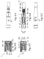
- Fig. 6A is a top view of the plug 1
- Fig. 6B is a longitudinal sectional view of the plug 1
- Fig. 6C is a bottom view of the plug 1.
- Fig 6D is a transverse sectional view of the receptacle 2
- Fig. 6E is a longitudinal sectional view of the receptacle 2.
- a columnar second protrusion 22A In the distal end surface of the pin contact-receiving portion 22, there is formed a columnar second protrusion 22A.
- the pin contact-receiving hole 2A is located in the center of the second protrusion 22A.
- the second reentrant 14A of the pin contact holder 14 is fitted to the second protrusion 22A of the pin contact-receiving portion 22. Therefore, the plug 1 is connected to the receptacle 2.
- the second reentrant 14A and the second protrusion 22A are specified in shape so that the connector can prevent any external antennas of other manufacturers from being connected to the receptacle 2.
- the invention is not limited the above-described embodiments, and it includes the modifications and improvements which are made within a scope such that the obj ect of the invention can be achieved.
- the connector of the present invention may have the function of wireless LAN and may be used for a notebook-sized PC or a PDA capable of switching between its external antenna and internal antenna.
- the connector of the present invention can provide the following advantages.
- the first protrusion of the pin contact holder is fitted in the first reentrant of the second receptacle housing, thereby to connect the plug to the receptacle.
- the first protrusion and the first reentrant are specified in shape so that the connector can prevent any external antennas of other manufacturers from being connected to the receptacle.
- the plug can be connected to the receptacle independently of the posture of the plug because it is not required to combine a key and a key groove like conventional cases. On this account, the plug can be readily connected to the receptacle.
Landscapes
- Coupling Device And Connection With Printed Circuit (AREA)
- Details Of Connecting Devices For Male And Female Coupling (AREA)
- Multi-Conductor Connections (AREA)
Abstract
Description
wherein said plug including a cylindrical shell connected to the outside conductor of said coaxial cable, a pin contact connected to the inside conductor of said coaxial cable, and an insulative pin contact holder provided inside the shell for holding the pin contact on a central axis of the shell;
wherein said receptacle including a first receptacle housing having a cylindrical shell-receiving hole in which the shell of said plug is to be plugged, and a second receptacle housing provided inside the shell-receiving hole and having a pin contact-receiving hole in which the pin contact is to be plugged;
wherein a first protrusion is formed in a distal end of the pin contact holder; and
wherein a first reentrant in which the first protrusion is to be fitted is formed in a distal end of the second receptacle housing. The connector may be used for compact systems adopting the wireless LAN. For example, the connector with an external antenna may be used in a high-speed wireless LAN standardized under IEEE 802.11a.The antenna may be, for example, an external antenna which is provided outside a system in which the connector is mounted. The antenna may be, for example, a wire antenna or a whip antenna. The transmitter-receiver terminal of the antenna are connected to the inside conductor of the coaxial cable, and the ground terminal thereof is connected to the outside conductor of the coaxial cable.The inside conductor of the coaxial cable may be, for example, a core wire, and may be fixed on the proximal end side of the pin contact by solder. In addition, the outside conductor of the coaxial cable may be, for example, a braided wire and may be pinched on the proximal end side of the cylindrical shell thereby to be fixed.The connecting portion of the plug and coaxial cable may be covered with an insulating protective cover. In this case, the protective ccver may be grasped thereby to put the plug in the receptacle and remove the plug from the receptacle.Grooved notches may be formed on its distal end side and proximal end side of the periphery of the pin contact holder respectively. The grooved notches may be engaged to the cylindrical shell to hold the pin contact holder in the cylindrical shell. Inside the second receptacle housing, a fixed contact and an elastically-deformable and movable contact urged toward the fixed contact may be provided. In this case, the pin contact is inserted in the pin contact-receiving hole. Thus, the distal end of the pin contact enters between the movable contact and the fixed contact and presses the movable contact to separate the movable contact from the fixed contact. In contrast, when the pin contact is withdrawn from the pin contact-receiving hole, the movable contact abuts the fixed contact thereby to be electrically connected to the fixed contact. Accordingly, the receptacle has a switching function.In addition, the receptacle may be disposed on a printed wiring board and fixed to a ground pattern on the board by solder.According to the invention of (1), the first protrusion of the pin contact holder is fitted in the first reentrant of the second receptacle housing, thereby to connect the plug to the receptacle. Thus, the first protrusion and the first reentrant are specified in shape so that the connector can prevent any external antennas of other manufacturers from being connected to the receptacle.In addition, the plug can be connected to the receptacle independently of the posture of the plug because it is not required to combine a key and a key groove like conventional cases. On this account, the plug can be readily connected to the receptacle.
wherein said plug including a cylindrical shell connected to the outside conductor of said coaxial cable, a pin contact connected to the inside conductor of said coaxial cable, and an insulative pin contact holder provided inside the shell for holding the pin contact on a central axis of the shell;
wherein said receptacle including a first receptacle housing having a cylindrical shell-receiving hole in which the shell of said plug is to be plugged, and a second receptacle housing provided inside the shell-receiving hole and having a pin contact-receiving hole in which the pin contact is to be plugged;
wherein a first reentrant formed in a distal end of the pin contact holder; and
wherein a first protrusion which the first reentrant is to be fitted in is formed in a distal end of the second receptacle housing. The connector may be used for compact systems adopting the wireless LAN. For example, the connector with an external antenna may be used in a high-speed wireless LAN standardized under IEEE 802.11a. The antenna may be, for example, an external antenna which is provided outside a system with the connector mounted therein. The antenna may be, for example, a wire antenna or a whip antenna. The transmitter-receiver terminal of the antenna are connected to the inside conductor of the coaxial cable, and the ground terminal thereof is connected to the outside conductor of the coaxial cable.The inside conductor of the coaxial cable may be, for example, a core wire, and may be fixed on the proximal end side of the pin contact by solder. In addition, the outside conductor of the coaxial cable may be, for example, a braided wire and may be pinched on the proximal end side of the cylindrical shell thereby to be fixed.The connecting portion of the plug and coaxial cable may be covered with an insulating protective cover. In this case, the protective cover may be grasped thereby to put the plug in the receptacle and remove the plug from the receptacle.Grooved notches may be formed on its distal end side and proximal end side of the periphery of the pin contact holder respectively. The grooved notches may be engaged to the cylindrical shell to hold the pin contact holder in the cylindrical shell.Inside the second receptacle housing, a fixed contact and an elastically-deformable and movable contact urged toward the fixed contact may be provided. In this case, the pin contact is inserted in the pin contact-receiving hole. Thus, the distal end of the pin contact enters between the movable contact and the fixed contact and presses the movable contact to separate the movable contact from the fixed contact. In contrast, when the pin contact is withdrawn from the pin contact-receiving hole, the movable contact abuts the fixed contact thereby to be electrically connected to the fixed contact. Accordingly, the receptacle has a switching function.In addi tion, the receptacle may be disposed on a printed wiring board and fixed to a ground pattern on the board by solder.According to the invention of (2), the first reentrant of the pin contact holder is fitted in the first protrusion of the second receptacle housing, thereby to connect the plug to the receptacle. Thus, the first protrusion and the first reentrant are specified in shape so that the connector can prevent any external antennas of other manufacturers from being connected to the receptacle.In addition, the plug can be connected to the receptacle independently of the posture of the plug because it is not required to combine a key and a key groove like conventional cases. On this account, the plug can be readily connected to the receptacle.
wherein an annular groove portion is formed in an outer peripheral surface of the shell of said plug, and
whereby the first pressing pieces of said receptacle are elastically deformed and engaged with a groove portion of said plug when said plug is plugged in said receptacle. According to the invention of (3), the connector has a half-lock structure to hold the plug in the receptacle by engaging the first pressing pieces with the annular groove portion. Therefore, the plug can be inserted in and drawn from the receptacle readily.
whereby the second pressing pieces of said receptacle are elastically deformed to steady the shell of said plug from its inside when said plug is plugged in said receptacle.
whereby the pin contact penetrates through the pin contact-receiving hole and presses the elastic contact to separate the elastic contact from the fixed contact when the pin contact is plugged in the pin contact-receiving hole.
Claims (8)
- A connector comprising:wherein said coaxial cable including an inside conductor extending in its axial direction, and an outside conductor provided outside the inside conductor and extending in its axial direction;a plug connected to an antenna through a coaxial cable; anda receptacle which said plug is to be put in and removed from;
wherein said plug including a cylindrical shell connected to the outside conductor of said coaxial cable, a pin contact connected to the inside conductor of said coaxial cable, and an insulative pin contact holder provided inside the shell for holding the pin contact on a central axis of the shell;
wherein said receptacle including a first receptacle housing having a cylindrical shell-receiving hole in which the shell of said plug is to be plugged, and a second receptacle housing provided inside the shell-receiving hole and having a pin contact-receiving hole in which the pin contact is to be plugged;
wherein a first protrusion is formed in a distal end of the pin contact holder; and
wherein a first reentrant in which the first protrusion is to be fitted is formed in a distal end of the second receptacle housing. - A connector comprising:wherein said coaxial cable including an inside conductor extending in its axial direction, and an outside conductor provided outside the inside conductor and extending in its axial direction;a plug connected to an antenna through a coaxial cable; anda receptacle which said plug is to be put in and removed from;
wherein said plug including a cylindrical shell connected to the outside conductor of said coaxial cable, a pin contact connected to the inside conductor of said coaxial cable, and an insulative pin contact holder provided inside the shell for holding the pin contact on a central axis of the shell;
wherein said receptacle including a first receptacle housing having a cylindrical shell-receiving hole in which the shell of said plug is to be plugged, and a second receptacle housing provided inside the shell-receiving hole and having a pin contact-receiving hole in which the pin contact is to be plugged;
wherein a first reentrant formed in a distal end of the pin contact holder; and
wherein a first protrusion which the first reentrant is to be fitted in is formed in a distal end of the second receptacle housing. - The connector according to Claim 1 or 2, wherein said receptacle includes elastically-deformable first pressing pieces protruded from an inner surface of the shell-receiving hole of the first receptacle housing,
wherein an annular groove portion is formed in an outer peripheral surface of the shell of said plug, and
whereby the first pressing pieces of said receptacle are elastically deformed and engaged with a groove portion of said plug when said plug is plugged in said receptacle. - The connector according to Claim 3, wherein the second receptacle housing is sandwiched between the first pressing pieces.
- The connector according to Claim 4, wherein said receptacle includes second pressing pieces protruded from an outer peripheral surface of the second receptacle housing, and
whereby the second pressing pieces of said receptacle are elastically deformed to steady the shell of said plug from its inside when said plug is plugged in said receptacle. - The connector according to Claims 1 or 2, wherein said receptacle includes a fixed contact and an elastically-deformable elastic contact abutting the fixed contact, and
whereby the pin contact penetrates through the pin contact-receiving hole and presses the elastic contact to separate the elastic contact from the fixed contact when the pin contact is plugged in the pin contact-receiving hole. - The connector according to Claims 1 or 2, wherein said plug is connected to an external antenna for wireless LAN.
- The connector according to Claims 1 or 2, wherein said plug is connected to an external antenna for high-speed wireless LAN standardised under IEEE 802.11a.
Applications Claiming Priority (2)
| Application Number | Priority Date | Filing Date | Title |
|---|---|---|---|
| JP2003155693 | 2003-05-30 | ||
| JP2003155693A JP4199597B2 (en) | 2003-05-30 | 2003-05-30 | Connector for antenna |
Publications (2)
| Publication Number | Publication Date |
|---|---|
| EP1482599A2 true EP1482599A2 (en) | 2004-12-01 |
| EP1482599A3 EP1482599A3 (en) | 2006-01-25 |
Family
ID=33128336
Family Applications (1)
| Application Number | Title | Priority Date | Filing Date |
|---|---|---|---|
| EP04012754A Withdrawn EP1482599A3 (en) | 2003-05-30 | 2004-05-28 | Connector |
Country Status (6)
| Country | Link |
|---|---|
| US (1) | US6976873B2 (en) |
| EP (1) | EP1482599A3 (en) |
| JP (1) | JP4199597B2 (en) |
| KR (1) | KR101013321B1 (en) |
| CN (1) | CN100367575C (en) |
| TW (1) | TWI292970B (en) |
Families Citing this family (17)
| Publication number | Priority date | Publication date | Assignee | Title |
|---|---|---|---|---|
| JP4331586B2 (en) * | 2003-12-25 | 2009-09-16 | 富士通株式会社 | Electronic equipment and housing for electronic equipment |
| TWI246809B (en) * | 2005-03-10 | 2006-01-01 | Avision Inc | Electrical connector capable of interrupting an ESD path |
| CN100420101C (en) * | 2005-04-15 | 2008-09-17 | 虹光精密工业(苏州)有限公司 | Electrical connectors that block the path of ESD |
| KR100593500B1 (en) * | 2005-11-23 | 2006-06-30 | (주)기가레인 | Plug for high frequency connector |
| KR100809054B1 (en) | 2006-09-07 | 2008-03-03 | (주)기가레인 | Connector for high frequency transmission with high electrical insulation |
| GB2469023B (en) * | 2009-03-30 | 2013-01-02 | Tyco Electronics Ltd Uk | Coaxial connector and method of assembling one |
| JP5286190B2 (en) * | 2009-08-03 | 2013-09-11 | 富士通コンポーネント株式会社 | Coaxial connector and connector device |
| CN201667463U (en) * | 2009-11-10 | 2010-12-08 | 富士康(昆山)电脑接插件有限公司 | Socket and its corresponding plug |
| TWI425719B (en) * | 2010-11-16 | 2014-02-01 | Compal Electronics Inc | Connecting port |
| CN103427189A (en) * | 2012-05-18 | 2013-12-04 | 凡甲电子(苏州)有限公司 | Socket connector |
| CN104218298B (en) * | 2013-05-29 | 2017-02-08 | 比亚迪股份有限公司 | NFC (Near Field Communication) antenna assembly |
| CN103904487A (en) * | 2014-03-18 | 2014-07-02 | 东莞讯滔电子有限公司 | Plug connector, socket connector and electric connector combination |
| CN106532258A (en) * | 2017-01-12 | 2017-03-22 | 成都天锐通科技有限公司 | Interference suppression antenna |
| EP3767750B1 (en) * | 2019-07-16 | 2022-03-02 | Rosenberger Hochfrequenztechnik GmbH & Co. KG | Electric connector, insulated safety element and method for mounting an electrical connector |
| CN112563721B (en) * | 2020-12-09 | 2024-05-07 | 安徽恒诺机电科技有限公司 | A protection against electric shock wiring sheath for antenna boom |
| JP7569504B2 (en) * | 2022-01-31 | 2024-10-18 | 住友電装株式会社 | Shielded Connectors |
| TWI886011B (en) * | 2023-11-22 | 2025-06-01 | 四零四科技股份有限公司 | Multipurpose receptacle electrical connector and related electrical connector assembly |
Family Cites Families (25)
| Publication number | Priority date | Publication date | Assignee | Title |
|---|---|---|---|---|
| DE7427964U (en) * | 1974-08-17 | 1975-01-30 | Bosch R Gmbh | Coaxial connector |
| US4593464A (en) * | 1983-08-15 | 1986-06-10 | Allied Corporation | Method of making a triaxial electrical connector |
| JPS6139381A (en) * | 1984-07-30 | 1986-02-25 | 株式会社東芝 | One touch type sealing connector |
| US4895521A (en) * | 1989-01-13 | 1990-01-23 | Amp Incorporated | Multi-port coaxial connector assembly |
| US5037328A (en) * | 1990-05-31 | 1991-08-06 | Amp Incorporated | Foldable dielectric insert for a coaxial contact |
| JP2626281B2 (en) * | 1991-03-18 | 1997-07-02 | 日本電気株式会社 | Coaxial connector |
| JP2604286B2 (en) | 1991-04-26 | 1997-04-30 | 日本圧着端子製造株式会社 | Rotating antenna |
| JPH0583025A (en) * | 1991-09-20 | 1993-04-02 | Ocean Cable Co Ltd | Metallic pipe slot array antenna |
| JPH05144526A (en) | 1991-11-25 | 1993-06-11 | Sony Corp | Antenna connector |
| JPH06140105A (en) | 1992-10-27 | 1994-05-20 | Matsushita Electric Works Ltd | Television terminal |
| JPH06310337A (en) | 1993-04-23 | 1994-11-04 | Murata Mfg Co Ltd | Antenna connector |
| FR2716039B1 (en) * | 1994-02-04 | 1996-04-26 | Radiall Sa | Coaxial electrical connector also performing a switching function. |
| EP0820649B1 (en) * | 1995-04-12 | 1999-10-13 | Itt Industries Limited | Electrical connector |
| JPH0992409A (en) * | 1995-09-25 | 1997-04-04 | Hosiden Corp | Multi-polar jack |
| JP3470249B2 (en) | 1995-12-06 | 2003-11-25 | 松下電器産業株式会社 | Antenna plug holder |
| US5730621A (en) * | 1996-04-10 | 1998-03-24 | Insert Enterprise Co., Ltd. | Dual-jack electrical connector |
| JPH09306603A (en) | 1996-05-08 | 1997-11-28 | Dai Ichi Denshi Kogyo Kk | Coaxial connector |
| JP3267890B2 (en) | 1997-03-06 | 2002-03-25 | ヒロセ電機株式会社 | Coaxial connector for antenna switching |
| JP3684803B2 (en) * | 1997-12-19 | 2005-08-17 | 松下電工株式会社 | Coaxial connector |
| JPH11251001A (en) | 1997-12-22 | 1999-09-17 | Whitaker Corp:The | Coaxial connector assembly |
| JPH11329611A (en) | 1998-05-08 | 1999-11-30 | Matsushita Electric Ind Co Ltd | Antenna plug |
| DE19929672B4 (en) * | 1999-06-28 | 2004-07-29 | Tyco Electronics Logistics Ag | Connector arrangement for coaxial lines |
| JP3293806B2 (en) | 1999-09-28 | 2002-06-17 | エヌイーシーアクセステクニカ株式会社 | Coaxial connector receptacle |
| JP4158877B2 (en) * | 2001-07-04 | 2008-10-01 | 古河電気工業株式会社 | Shield connector |
| US6733336B1 (en) * | 2003-04-03 | 2004-05-11 | John Mezzalingua Associates, Inc. | Compression-type hard-line connector |
-
2003
- 2003-05-30 JP JP2003155693A patent/JP4199597B2/en not_active Expired - Fee Related
-
2004
- 2004-04-06 TW TW093109410A patent/TWI292970B/en not_active IP Right Cessation
- 2004-04-30 KR KR1020040030281A patent/KR101013321B1/en not_active Expired - Fee Related
- 2004-05-26 CN CNB2004100428561A patent/CN100367575C/en not_active Expired - Fee Related
- 2004-05-28 EP EP04012754A patent/EP1482599A3/en not_active Withdrawn
- 2004-05-28 US US10/855,423 patent/US6976873B2/en not_active Expired - Fee Related
Also Published As
| Publication number | Publication date |
|---|---|
| CN100367575C (en) | 2008-02-06 |
| EP1482599A3 (en) | 2006-01-25 |
| US20040242073A1 (en) | 2004-12-02 |
| JP4199597B2 (en) | 2008-12-17 |
| TW200511663A (en) | 2005-03-16 |
| CN1574505A (en) | 2005-02-02 |
| TWI292970B (en) | 2008-01-21 |
| JP2004356067A (en) | 2004-12-16 |
| KR20040104361A (en) | 2004-12-10 |
| US6976873B2 (en) | 2005-12-20 |
| KR101013321B1 (en) | 2011-02-09 |
Similar Documents
| Publication | Publication Date | Title |
|---|---|---|
| US6976873B2 (en) | Connector | |
| US11901678B2 (en) | Contact member for electrical connector | |
| US7727029B2 (en) | Connector arrangement having multiple independent connectors | |
| US10027073B2 (en) | Coaxial connector with electromagnetic shield | |
| US7819680B2 (en) | Surface mount coaxial connector with switching function | |
| EP2319134A1 (en) | Low-profile mounted push-on connector | |
| US6966797B2 (en) | High-speed cable assembly | |
| US11929550B2 (en) | Wireless communication connector and communication module comprising same | |
| TWI247498B (en) | Connector unit | |
| US6648684B2 (en) | Radio frequency cable connector | |
| TW202105859A (en) | Coaxial cable male connector for transmitting super-high frequency signals | |
| US7704078B2 (en) | Systems for wireless antenna connection | |
| US6417812B1 (en) | Electrical connector incorporating antenna | |
| US7399206B2 (en) | Coaxial connector | |
| US20190148867A1 (en) | Electrical connector | |
| US8866696B2 (en) | Antenna with integrated RF module | |
| JP2006164669A (en) | Connector, connection detection system, input switching system | |
| CN222995989U (en) | Radio frequency connector and connector combination | |
| JP2000150088A (en) | Connector device for video camera | |
| CN119133956A (en) | RF connectors and connector assemblies | |
| JP2000299173A (en) | Coaxial plug connector | |
| JP2009032604A (en) | Antenna connector |
Legal Events
| Date | Code | Title | Description |
|---|---|---|---|
| PUAI | Public reference made under article 153(3) epc to a published international application that has entered the european phase |
Free format text: ORIGINAL CODE: 0009012 |
|
| AK | Designated contracting states |
Kind code of ref document: A2 Designated state(s): AT BE BG CH CY CZ DE DK EE ES FI FR GB GR HU IE IT LI LU MC NL PL PT RO SE SI SK TR |
|
| AX | Request for extension of the european patent |
Extension state: AL HR LT LV MK |
|
| PUAL | Search report despatched |
Free format text: ORIGINAL CODE: 0009013 |
|
| AK | Designated contracting states |
Kind code of ref document: A3 Designated state(s): AT BE BG CH CY CZ DE DK EE ES FI FR GB GR HU IE IT LI LU MC NL PL PT RO SE SI SK TR |
|
| AX | Request for extension of the european patent |
Extension state: AL HR LT LV MK |
|
| 17P | Request for examination filed |
Effective date: 20060321 |
|
| AKX | Designation fees paid |
Designated state(s): DE FR GB |
|
| 17Q | First examination report despatched |
Effective date: 20120105 |
|
| STAA | Information on the status of an ep patent application or granted ep patent |
Free format text: STATUS: THE APPLICATION IS DEEMED TO BE WITHDRAWN |
|
| 18D | Application deemed to be withdrawn |
Effective date: 20120516 |