US5037328A - Foldable dielectric insert for a coaxial contact - Google Patents
Foldable dielectric insert for a coaxial contact Download PDFInfo
- Publication number
- US5037328A US5037328A US07/531,192 US53119290A US5037328A US 5037328 A US5037328 A US 5037328A US 53119290 A US53119290 A US 53119290A US 5037328 A US5037328 A US 5037328A
- Authority
- US
- United States
- Prior art keywords
- contact
- insert
- ferrule
- coaxial
- center
- Prior art date
- Legal status (The legal status is an assumption and is not a legal conclusion. Google has not performed a legal analysis and makes no representation as to the accuracy of the status listed.)
- Expired - Lifetime
Links
Images


Classifications
-
- H—ELECTRICITY
- H01—ELECTRIC ELEMENTS
- H01R—ELECTRICALLY-CONDUCTIVE CONNECTIONS; STRUCTURAL ASSOCIATIONS OF A PLURALITY OF MUTUALLY-INSULATED ELECTRICAL CONNECTING ELEMENTS; COUPLING DEVICES; CURRENT COLLECTORS
- H01R24/00—Two-part coupling devices, or either of their cooperating parts, characterised by their overall structure
- H01R24/38—Two-part coupling devices, or either of their cooperating parts, characterised by their overall structure having concentrically or coaxially arranged contacts
- H01R24/40—Two-part coupling devices, or either of their cooperating parts, characterised by their overall structure having concentrically or coaxially arranged contacts specially adapted for high frequency
-
- H—ELECTRICITY
- H01—ELECTRIC ELEMENTS
- H01R—ELECTRICALLY-CONDUCTIVE CONNECTIONS; STRUCTURAL ASSOCIATIONS OF A PLURALITY OF MUTUALLY-INSULATED ELECTRICAL CONNECTING ELEMENTS; COUPLING DEVICES; CURRENT COLLECTORS
- H01R9/00—Structural associations of a plurality of mutually-insulated electrical connecting elements, e.g. terminal strips or terminal blocks; Terminals or binding posts mounted upon a base or in a case; Bases therefor
- H01R9/03—Connectors arranged to contact a plurality of the conductors of a multiconductor cable, e.g. tapping connections
- H01R9/05—Connectors arranged to contact a plurality of the conductors of a multiconductor cable, e.g. tapping connections for coaxial cables
- H01R9/0518—Connection to outer conductor by crimping or by crimping ferrule
-
- H—ELECTRICITY
- H01—ELECTRIC ELEMENTS
- H01R—ELECTRICALLY-CONDUCTIVE CONNECTIONS; STRUCTURAL ASSOCIATIONS OF A PLURALITY OF MUTUALLY-INSULATED ELECTRICAL CONNECTING ELEMENTS; COUPLING DEVICES; CURRENT COLLECTORS
- H01R2103/00—Two poles
Definitions
- This invention relates to disposing a center contact in a coaxial contact, and in particular to a two-piece dielectric insert for positioning a center contact in a coaxial contact and for insulating the center contact from the surrounding conductive shell.
- Dielectric inserts used to position a center contact in a coaxial contact have typically been annular in structure, taking the shape of a cylinder with a bore through the center.
- the center coaxial contact is passed partially through the bore and secured.
- a necessary result is that the diameter of the bore must be large enough to accommodate the largest cross section of the contact portion passed into or through the bore.
- a coaxial contact for termination to a coaxial cable having a center conductor surrounded by a dielectric material thence a braid and jacket.
- the coaxial contact has a center contact with a mating portion, a conductor attaching portion and a shank extending therebetween.
- a first substantially semi-cylindrical insert member having an axial recess adapted to receive at least a portion of the center contact is positioned adjacent the center contact.
- a second substantially semi-cylindrical dielectric insert member is adapted to be positioned over the first insert member resulting in a substantially cylindrical dielectric structure that surrounds a portion of the center contact.
- An electrically conductive shell receives the cylindrical structure and secures the subassembly together.
- the shell has a forward cylindrical contact portion and a cable attaching, braid engaging portion.
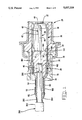
- FIG. 1 is a partial cross section through a receptacle connector showing a coax center contact secured in a receptacle coaxial contact by a two-piece dielectric insert, in accordance with the present invention
- FIG. 2 is a partial cross section through a plug connector showing a coax center contact secured in a plug coaxial contact by a two-piece dielectric insert;
- FIG. 3A shows a two-piece dielectric insert for a small diameter dielectric coaxial cable
- FIG. 3B shows a two-piece dielectric insert for a large diameter coaxial cable
- FIG. 4 is a pin center contact
- FIG. 5 is a receptacle center contact
- FIG. 6A is a ferrule for use with the insert of FIG. 3A;
- FIG. 6B is a ferrule for use with the insert of FIG. 3B;
- FIG. 7 is a side view of a receptacle shell
- FIG. 8 is a front view of the receptacle shell of FIG. 7;
- FIG. 9 is a side view of a plug shell.
- FIGS. 10A-F are a sequence of Figures showing the assembly of the insert to a center contact and ferrule.
- a connector 20 is shown in FIG. 1 including a receptacle coaxial contact 22 having a center contact 24 secured therein by a two-piece dielectric insert 26 in accordance with the present invention.
- Coaxial contact 22 also includes a ferrule 28 and receptacle shell 30.
- Connector 20 includes front and rear dielectric housing members 32,34 and, if shielded, includes front and rear shell means 36,38.
- Coaxial contact 22 may be used in conjunction with connector 20 or alone. When used in conjunction with connector 20, contact 22 may be secured in connector 20 in accordance with the teaching of concurrently filed U.S. patent application No. 07/531,212, now U.S. Pat. No. 4,990,104, entitled "Snap-In Retention System For Coaxial Contact," the disclosure of which is hereby incorporated by reference, or any other known method.
- Pin contact 40 is typically stamped and formed from electrically conductive material such as brass stock and has a mating portion 42 with tapered end 44 to facilitate mating, a terminating portion 46 in the form of crimp barrel 48 and a reduced diameter shank 50 between the mating and terminating portions.
- the difference in diameter between shank 50 and mating portion 42 defines rearwardly facing annular shoulder 52.
- Shank 50 thus extends between shoulders 52 and 54.
- a plug coaxial contact 22' secured in connector 20' is shown in FIG. 2.
- Connector 20' includes front and rear dielectric housing members 32',34' and if shielded includes front and rear shell means 36' and 38'.
- the center contact 24 is shown as a receptacle contact 56.
- a top view of an unterminated receptacle contact 56 is shown in FIG. 5.
- Contact 56 is also typically stamped and formed from phosphor bronze stock and has a cylindrical barrel 58 formed with cantilever beams 60 extending therefrom for receiving therebetween mating portion 42 of a pin contact, a terminating portion 62 in the form of a crimped barrel 64, and a reduced diameter shank 66 between the cylindrical barrel and crimp barrel.
- shank 66 and cylindrical barrel 58 define a rearwardly facing annular shoulder 68.
- shank 66 extends between shoulders 68 and 70.
- a drawn conductive ferrule 28, is shown in cross section in FIG. 6A for a small diameter cable and a ferrule 28' is shown in cross section in FIG. 6B for a large diameter cable. While the ferrule in the preferred embodiment is a drawn member, such a ferrule could also be stamped and formed. Ferrules 28 and 28' are electrically conductive and typically manufactured from a copper alloy. Each ferrule has a large diameter forward end 76,76', a tapered section 78,78' and a reduced diameter cylindrical rear section 80,80'. Each cylindrical section has an annular ridge 82,82' of larger diameter than the respective reduced diameter cylindrical rear section proximate the free edge 84,84', with free edge 84,84' defining a cable entry 86,86'.
- FIG. 7 The side view of a receptacle shell 30 is shown in FIG. 7.
- shell 30 is stamped and formed from phasphor bronze strip stock.
- Receptacle shell 30 has a hollow generally cylindrical shape having a slotted forward end 90 forming cantilever beams 92.
- Each beam 92 has an arcuate recess 94 proximate distal end 96, collectively forming a reduced diameter plug receiving opening 98 best seen in FIG. 8.
- plug shell 30 is manufactured of stock that has been strip gold plated such that the plating is on inner arcuate surfaces 100.
- the inner surface 100 of recesses 94 engage and wipe the exterior surface 102 of a plug shell 104 shown in FIG. 9 as plug and receptacle contacts are mated or unmated.
- Inner surfaces 100 provide redundant points of electrical and mechanical contact with the exterior surface of a mated plug shell.
- Forward end 90 extends rearward through a retention section 106, described in more detail in concurrently filed U.S. application Ser. No. 07/531,212, now U.S. Pat. No. 4,990,104 and a rear cylindrical ferrule receiving section 108.
- a portion of section 108 extends rearward forming extension 110 with crimp tabs 112 and 114 extending upwardly therefrom.
- Receptacle shell 30 has forward stops 140 formed from a shear line segment 142 when stop 140 is formed inwardly relative to front end 90. Stops 140 provide arcuate stop shoulders 144 which assists in positioning insert 26 upon insertion into shell 30 and prevents over-insertion of insert 26.
- Plug shell 104 has a hollow, generally cylindrical shape. Shell 104 is typically stamped and formed of brass. Shell 104 has a reduced diameter forward end 116 the outside surface 118 of which is typically gold plated. Forward end 116 is sized such that the outer diameter is receivable within opening 98 of forward end 90 of receptacle shell 30. Forward end 116 extends rearward to a transition region 120 of conical shape that tapers to a larger diameter section 122 that may have a retention section 126 therein.
- Section 122 includes ferrule receiving section 128 and insert receiving section 124 which have substantially the same inside diameter in the preferred embodiment and are substantially the same inside diameter as forward end 90 and ferrule receiving section 108 of receptacle shell 30.
- Ferrule receiving sections 108 and 128 have an inside diameter sized to receive the forward end 76 or 76' of ferrules 28 or 28' as best seen in FIGS. 1 and 2.
- a portion of ferrule receiving section 128 extends rearward forming extension 130 with crimp tabs 132 and 134 extending upwardly therefrom.
- Plug shell 104 has stops 150 formed from a shear line segment 152. Stop 150 is formed inwardly relative to shell 104 resulting in an arcuate stop shoulder 154 which positions insert 26 upon insertion into shell 104 and prevents over-insertion of insert 26.
- FIGS. 3A and 3B Two embodiments of a two-piece dielectric insert are shown in FIGS. 3A and 3B.
- the major difference between the two embodiments permits one of the inserts to accommodate a larger diameter coaxial cable.
- the FIG. 3A embodiment will be described; the same reference number having a prime notation will refer to similar structure in the embodiment of FIG. 3B.
- a two-piece dielectric insert 26 is comprised of two substantially identical halves 160,162.
- Halves 160,162 in the preferred embodiment are molded of polyolefin and are hingedly interconnected by web 164.
- Each half has a forward portion 166 and a rearward portion 168.
- Each forward portion is substantially semi-cylindrical having a semi-cylindrical channel 170 coaxially disposed therein.
- Forward surface 172 is semi-annular in shape and engages a stop shoulder 144 or 154 upon insertion of insert 26 into shell 30 or 104 respectively.
- the edge of surface 172 along semi-cylindrical side wall 174 may be beveled 176 to facilitate entry of insert 26 into a shell.
- the rear of forward portion 166 is defined by inner semi-annular surface 178 concentrically disposed about channel 170 and outer semi-annular surface 180 also concentrically disposed about channel 170.
- the spacing or distance between surfaces 172 and 178 is substantially the same spacing or distance between shoulders 52 and 54 of pin contact 40 (see FIG. 4), or the distance between shoulders 68 and 70 of receptacle contact 56 (see FIG. 5).
- the radius of semi-cylindrical channel 170 is substantially the same as or slightly smaller than the radius of shank 50 of a pin contact 40 or shank 66 of a receptacle contact 56.
- Rearward portion 168 extends from and is integral with forward portion 160 of each half 160,162 between inner semi-annular surface 178 and outer semi-annular surface 180.
- Rearward portion 160 is substantially semi-cylindrical having a semi-cylindrical channel 182 coaxially disposed therein and extending from semiannular surface 178 rearward.
- the radius of channel 182 is typically larger than the radius of channel 170 as channel 170 accommodates the shank of a center contact 24 while channel 182 accommodates the crimped barrel of a center contact 24.
- rearward portions 168 form a cylindrical structure with two semi-cylindrical channels 182 forming a centrally located cylindrical bore therethrough.
- Rearward portion 168 may be beveled 184 at the trailing edge to be received in a tapered portion of a ferrule 28 or 28'.
- a portion of channels 182 may be enlarged to form a larger diameter channel portion 186' to receive the dielectric of the cable being terminated to permit the insulative insert to overlap the coax cable dielectric.
- the distance from semi-annular surface 178,178' to semiannular surface 188' is substantially the length of the crimp barrel of a center contact between shoulder 54 or 70 and rear end 210.
- the outside diameter of the rearward portion, when halves 160,162 are folded about web 164, is sized to be closely received within the forward end 76,76' of ferrule 28,28' with the leading edge 190,190' of ferrule 28,28' abutting semi-annular surfaces 180 in the assembled contact to position and secure insert 26 in the desired location within shell 30 or 104.
- arcuate stop shoulders 144 and 154 provide a forward stop for insert 26 or 26' while surfaces 180 or 180' provide a rear stop for the insert.
- Each receptacle contact 22 thus comprises a center contact 24 in the form of pin contact 40, a two-piece dielectric insert 26 or 26', a shell 30 and a ferrule 28 or 28'.
- Each plug contact 22' comprises a center contact 24, in the form of receptacle contact 56, a two-piece dielectric insert 26 or 26', a shell 104 and a ferrule 28 or 28'.
- Plug contact 22' may include an insulated tapered lead-in insert 192 (in accordance with concurrently filed U.S. patent application Ser. No. 07/521,204, now U.S. Pat. No. 4,990,105, entitled "Tapered Lead-In Insert For A Coaxial Contact", the disclosure of which is hereby incorporated by reference).
- Other than insert 192 in the preferred embodiment, air is the only dielectric separating center contact 24 from shell 30 or 104 forward of surface 172 of insert 26.
- Coaxial contacts 22 and 22' may be assembled and terminated to a coaxial cable manually or using automated assembly equipment. The assembly procedure will be described with reference to the sequence of FIGS. 10A-E.
- FIG. 10A shows a coaxial cable 200 for terminating to a coaxial contact.
- the coaxial contact may be any of the contacts described herein.
- the jacket 202, braid 204 and dielectric 206 of the cable have been removed to expose a length of approximately 6.75 mm of the center conductor 208. Further, jacket 202 has been removed to expose a length of approximately 25 mm of the braid.
- the stripped center conductor 208 is laid into the open crimp barrel 48 or 64 of a center contact 24.
- the cable dielectric 206 is butted against the rear end 210 of the crimp barrel.
- the center conductor is crimped in the crimp barrel thereby securing the center conductor to the coax center contact to complete a mechanical and electrical connection therebetween.
- the coax cable braid 204 is splayed and the terminated center contact 24 is passed into cable entry 86 or 86' and through a ferrule 28 or 28' appropriate for the diameter of cable 200. Alternatively, it may be stated that the ferrule is passed over the center contact.
- the ferrule is slid axially along the cable, with cylindrical section 80,80' between the cable dielectric 206 and the braid 204 to a position with the leading edge 190,190' beyond the crimp barrel of the center contact as shown in FIG. 10B.
- the center contact 24 is positioned in channels 170,182 or 170',182' of one half 160 or 162 With the crimp barrel being received in channel 182 and with shoulder 54,74 abutting semiannular surface 178 and with shank 50,66 received in channel 170, and shoulder 52,68 abutting forward surface 172.
- the other half 162 or 160 is positioned over the center contact, or if web 164 is present the other half is folded at web 164 around the center contact.
- insert 26 is held to maintain the center contact in position while the ferrule is slid axially along the cable toward the end of the mating contact such that rearward portions of the insert are received within forward end 76 of the ferrule until leading edge 190,190' engages outer semi-annular surfaces 180,180'. In this position, insert 26 is prevented from being removed inadvertently from contact 24. Insert 26 will not slide axially toward the unterminated end of center contact 24 due to the forward surfaces 172 engaging shoulders 52 or 68. In order to be removed, the two halves must be separated from each other to allow channels 170 to pass over shoulders 52 or 68. Thus, with insert 26 partially within ferrule 28,28', the center contact is held centered in insert 26 which is in turn centered within the ferrule.
- the cable braid 204 is then smoothed out to surround the smaller diameter cylindrical section 80,80' of the ferrule as shown in FIG. 10D.
- the above subassembly 212,212' is then inserted into the ferrule receiving end of a shell 30 or 104 until forward surface 172 or 172' engages forward stops 140,150, specifically the arcuate stop shoulders 144 or 154 as shown in FIG. 10E. This properly positions center contact 40, insert 26,26', ferrule 28,28' and subassembly 212,212' within shell 30,104 with center contact 24 coaxially centered in the shell.
- tabs 112,114 or 132,134 are then crimped over the braid to secure the shell to the subassembly and to complete an electrical path from shell 30,104 to braid 204. Crimping the tabs completes the assembly of the coax contact with the crimped tabs securing all parts of the connector together.
- the crimped tabs are between the annular ridge 82 and forward end 76 with the larger diameter of annular ridge 82 preventing the crimped tabs from otherwise sliding off cylindrical section 80,80'.
- the completed coaxial contact 22,22' may be inserted into dielectric housing means 34,36 if desired.
Abstract
A coaxial contact (22) for termination to a coaxial cable (200) having a center conductor (208) surrounded by a dielectric material (206) thence a braid (204) and jacket. The coaxial contact (22) has a center contact (24) with a mating portion (42), a conductor attaching portion (46) and a shank (50) extending therebetween. A first substantially semi-cylindrical insert member (160) having an axial recess (170) adapted to receive at least a portion of the center contact (24) is positioned adjacent the center contact (24), A second substantially semi-cylindrical dielectric insert member(162) is adapted to be positioned over the first insert member (160) resulting in a substantially cylindrical dielectric structure (26) that surrounds a portion of the center contact (24). A ferrule (28, 28') is positioned over a portion of the dielectric insert. An electrically conductive shell secures the subassembly together. The shell has a forward cylindrical contact portion (76) and a cable attaching, braid engaging portion (80).
Description
This invention relates to disposing a center contact in a coaxial contact, and in particular to a two-piece dielectric insert for positioning a center contact in a coaxial contact and for insulating the center contact from the surrounding conductive shell.
Dielectric inserts used to position a center contact in a coaxial contact have typically been annular in structure, taking the shape of a cylinder with a bore through the center. The center coaxial contact is passed partially through the bore and secured. A necessary result is that the diameter of the bore must be large enough to accommodate the largest cross section of the contact portion passed into or through the bore.
There is disclosed in U.S. Pat. No. 3,699,504 an open barrel coaxial cable terminal including a sleeve formed from a dielectric material having resilient buttons for insertion into and snap-in retention in a sleeve portion. The sleeve portion of the terminal is freely insertable within the inner diameter portion of the dielectric sleeve.
It would be desirable to have a dielectric insert to position a center coaxial contact that does not require passing the center contact through a central bore and would provide for a passage through the insert commensurate with the varying cross section of the contact to be received therein. Such an insert would more accurately align and hold the contact in a desired position.
In accordance with the present invention, a coaxial contact for termination to a coaxial cable having a center conductor surrounded by a dielectric material thence a braid and jacket. The coaxial contact has a center contact with a mating portion, a conductor attaching portion and a shank extending therebetween. A first substantially semi-cylindrical insert member having an axial recess adapted to receive at least a portion of the center contact is positioned adjacent the center contact. A second substantially semi-cylindrical dielectric insert member is adapted to be positioned over the first insert member resulting in a substantially cylindrical dielectric structure that surrounds a portion of the center contact. An electrically conductive shell receives the cylindrical structure and secures the subassembly together. The shell has a forward cylindrical contact portion and a cable attaching, braid engaging portion.
FIG. 1 is a partial cross section through a receptacle connector showing a coax center contact secured in a receptacle coaxial contact by a two-piece dielectric insert, in accordance with the present invention;
FIG. 2 is a partial cross section through a plug connector showing a coax center contact secured in a plug coaxial contact by a two-piece dielectric insert;
FIG. 3A shows a two-piece dielectric insert for a small diameter dielectric coaxial cable;
FIG. 3B shows a two-piece dielectric insert for a large diameter coaxial cable;
FIG. 4 is a pin center contact;
FIG. 5 is a receptacle center contact;
FIG. 6A is a ferrule for use with the insert of FIG. 3A;
FIG. 6B is a ferrule for use with the insert of FIG. 3B;
FIG. 7 is a side view of a receptacle shell;
FIG. 8 is a front view of the receptacle shell of FIG. 7;
FIG. 9 is a side view of a plug shell; and
FIGS. 10A-F are a sequence of Figures showing the assembly of the insert to a center contact and ferrule.
A connector 20 is shown in FIG. 1 including a receptacle coaxial contact 22 having a center contact 24 secured therein by a two-piece dielectric insert 26 in accordance with the present invention. Coaxial contact 22 also includes a ferrule 28 and receptacle shell 30. Connector 20 includes front and rear dielectric housing members 32,34 and, if shielded, includes front and rear shell means 36,38. Coaxial contact 22 may be used in conjunction with connector 20 or alone. When used in conjunction with connector 20, contact 22 may be secured in connector 20 in accordance with the teaching of concurrently filed U.S. patent application No. 07/531,212, now U.S. Pat. No. 4,990,104, entitled "Snap-In Retention System For Coaxial Contact," the disclosure of which is hereby incorporated by reference, or any other known method.
A plug coaxial contact 22' secured in connector 20' is shown in FIG. 2. Connector 20' includes front and rear dielectric housing members 32',34' and if shielded includes front and rear shell means 36' and 38'. The center contact 24 is shown as a receptacle contact 56. A top view of an unterminated receptacle contact 56 is shown in FIG. 5. Contact 56 is also typically stamped and formed from phosphor bronze stock and has a cylindrical barrel 58 formed with cantilever beams 60 extending therefrom for receiving therebetween mating portion 42 of a pin contact, a terminating portion 62 in the form of a crimped barrel 64, and a reduced diameter shank 66 between the cylindrical barrel and crimp barrel. The differential diameter between shank 66 and cylindrical barrel 58 defines a rearwardly facing annular shoulder 68. The difference in diameter between shank 66 and barrel 64, when crimped, defines forwardly facing shoulder 70. Thus, shank 66 extends between shoulders 68 and 70.
A drawn conductive ferrule 28, is shown in cross section in FIG. 6A for a small diameter cable and a ferrule 28' is shown in cross section in FIG. 6B for a large diameter cable. While the ferrule in the preferred embodiment is a drawn member, such a ferrule could also be stamped and formed. Ferrules 28 and 28' are electrically conductive and typically manufactured from a copper alloy. Each ferrule has a large diameter forward end 76,76', a tapered section 78,78' and a reduced diameter cylindrical rear section 80,80'. Each cylindrical section has an annular ridge 82,82' of larger diameter than the respective reduced diameter cylindrical rear section proximate the free edge 84,84', with free edge 84,84' defining a cable entry 86,86'.
The side view of a receptacle shell 30 is shown in FIG. 7. In the preferred embodiment, shell 30 is stamped and formed from phasphor bronze strip stock. Receptacle shell 30 has a hollow generally cylindrical shape having a slotted forward end 90 forming cantilever beams 92. Each beam 92 has an arcuate recess 94 proximate distal end 96, collectively forming a reduced diameter plug receiving opening 98 best seen in FIG. 8. Typically, plug shell 30 is manufactured of stock that has been strip gold plated such that the plating is on inner arcuate surfaces 100. The inner surface 100 of recesses 94 engage and wipe the exterior surface 102 of a plug shell 104 shown in FIG. 9 as plug and receptacle contacts are mated or unmated. Inner surfaces 100 provide redundant points of electrical and mechanical contact with the exterior surface of a mated plug shell. Forward end 90 extends rearward through a retention section 106, described in more detail in concurrently filed U.S. application Ser. No. 07/531,212, now U.S. Pat. No. 4,990,104 and a rear cylindrical ferrule receiving section 108. A portion of section 108 extends rearward forming extension 110 with crimp tabs 112 and 114 extending upwardly therefrom.
A side view of a plug shell is shown in FIG. 9. Plug shell 104 has a hollow, generally cylindrical shape. Shell 104 is typically stamped and formed of brass. Shell 104 has a reduced diameter forward end 116 the outside surface 118 of which is typically gold plated. Forward end 116 is sized such that the outer diameter is receivable within opening 98 of forward end 90 of receptacle shell 30. Forward end 116 extends rearward to a transition region 120 of conical shape that tapers to a larger diameter section 122 that may have a retention section 126 therein. Section 122 includes ferrule receiving section 128 and insert receiving section 124 which have substantially the same inside diameter in the preferred embodiment and are substantially the same inside diameter as forward end 90 and ferrule receiving section 108 of receptacle shell 30. Ferrule receiving sections 108 and 128 have an inside diameter sized to receive the forward end 76 or 76' of ferrules 28 or 28' as best seen in FIGS. 1 and 2. A portion of ferrule receiving section 128 extends rearward forming extension 130 with crimp tabs 132 and 134 extending upwardly therefrom.
Two embodiments of a two-piece dielectric insert are shown in FIGS. 3A and 3B. The major difference between the two embodiments permits one of the inserts to accommodate a larger diameter coaxial cable. The FIG. 3A embodiment will be described; the same reference number having a prime notation will refer to similar structure in the embodiment of FIG. 3B.
A two-piece dielectric insert 26 is comprised of two substantially identical halves 160,162. Halves 160,162 in the preferred embodiment are molded of polyolefin and are hingedly interconnected by web 164. Each half has a forward portion 166 and a rearward portion 168. Each forward portion is substantially semi-cylindrical having a semi-cylindrical channel 170 coaxially disposed therein. Forward surface 172 is semi-annular in shape and engages a stop shoulder 144 or 154 upon insertion of insert 26 into shell 30 or 104 respectively. The edge of surface 172 along semi-cylindrical side wall 174 may be beveled 176 to facilitate entry of insert 26 into a shell. The rear of forward portion 166 is defined by inner semi-annular surface 178 concentrically disposed about channel 170 and outer semi-annular surface 180 also concentrically disposed about channel 170.
The spacing or distance between surfaces 172 and 178 is substantially the same spacing or distance between shoulders 52 and 54 of pin contact 40 (see FIG. 4), or the distance between shoulders 68 and 70 of receptacle contact 56 (see FIG. 5). The radius of semi-cylindrical channel 170 is substantially the same as or slightly smaller than the radius of shank 50 of a pin contact 40 or shank 66 of a receptacle contact 56. When halves 160 and 162 are positioned over each other in the absence of web 164 or when the two halves are folded about web 164, the two forward portions 166 form a cylindrical structure with the two semi-cylindrical channels 170 forming a centrally located cylindrical bore therethrough.
The outside diameter of the rearward portion, when halves 160,162 are folded about web 164, is sized to be closely received within the forward end 76,76' of ferrule 28,28' with the leading edge 190,190' of ferrule 28,28' abutting semi-annular surfaces 180 in the assembled contact to position and secure insert 26 in the desired location within shell 30 or 104. Thus, arcuate stop shoulders 144 and 154 provide a forward stop for insert 26 or 26' while surfaces 180 or 180' provide a rear stop for the insert.
Each receptacle contact 22 thus comprises a center contact 24 in the form of pin contact 40, a two-piece dielectric insert 26 or 26', a shell 30 and a ferrule 28 or 28'. Each plug contact 22' comprises a center contact 24, in the form of receptacle contact 56, a two-piece dielectric insert 26 or 26', a shell 104 and a ferrule 28 or 28'. Plug contact 22' may include an insulated tapered lead-in insert 192 (in accordance with concurrently filed U.S. patent application Ser. No. 07/521,204, now U.S. Pat. No. 4,990,105, entitled "Tapered Lead-In Insert For A Coaxial Contact", the disclosure of which is hereby incorporated by reference). Other than insert 192, in the preferred embodiment, air is the only dielectric separating center contact 24 from shell 30 or 104 forward of surface 172 of insert 26.
FIG. 10A shows a coaxial cable 200 for terminating to a coaxial contact. The coaxial contact may be any of the contacts described herein. The jacket 202, braid 204 and dielectric 206 of the cable have been removed to expose a length of approximately 6.75 mm of the center conductor 208. Further, jacket 202 has been removed to expose a length of approximately 25 mm of the braid. The stripped center conductor 208 is laid into the open crimp barrel 48 or 64 of a center contact 24. Preferably, the cable dielectric 206 is butted against the rear end 210 of the crimp barrel. The center conductor is crimped in the crimp barrel thereby securing the center conductor to the coax center contact to complete a mechanical and electrical connection therebetween. The coax cable braid 204 is splayed and the terminated center contact 24 is passed into cable entry 86 or 86' and through a ferrule 28 or 28' appropriate for the diameter of cable 200. Alternatively, it may be stated that the ferrule is passed over the center contact.
The ferrule is slid axially along the cable, with cylindrical section 80,80' between the cable dielectric 206 and the braid 204 to a position with the leading edge 190,190' beyond the crimp barrel of the center contact as shown in FIG. 10B.
As shown in FIG. 10C, the center contact 24 is positioned in channels 170,182 or 170',182' of one half 160 or 162 With the crimp barrel being received in channel 182 and with shoulder 54,74 abutting semiannular surface 178 and with shank 50,66 received in channel 170, and shoulder 52,68 abutting forward surface 172. The other half 162 or 160 is positioned over the center contact, or if web 164 is present the other half is folded at web 164 around the center contact.
The forward end of the insert is held to maintain the center contact in position while the ferrule is slid axially along the cable toward the end of the mating contact such that rearward portions of the insert are received within forward end 76 of the ferrule until leading edge 190,190' engages outer semi-annular surfaces 180,180'. In this position, insert 26 is prevented from being removed inadvertently from contact 24. Insert 26 will not slide axially toward the unterminated end of center contact 24 due to the forward surfaces 172 engaging shoulders 52 or 68. In order to be removed, the two halves must be separated from each other to allow channels 170 to pass over shoulders 52 or 68. Thus, with insert 26 partially within ferrule 28,28', the center contact is held centered in insert 26 which is in turn centered within the ferrule.
The cable braid 204 is then smoothed out to surround the smaller diameter cylindrical section 80,80' of the ferrule as shown in FIG. 10D.
The above subassembly 212,212' is then inserted into the ferrule receiving end of a shell 30 or 104 until forward surface 172 or 172' engages forward stops 140,150, specifically the arcuate stop shoulders 144 or 154 as shown in FIG. 10E. This properly positions center contact 40, insert 26,26', ferrule 28,28' and subassembly 212,212' within shell 30,104 with center contact 24 coaxially centered in the shell.
As shown in FIG. 10F, tabs 112,114 or 132,134 are then crimped over the braid to secure the shell to the subassembly and to complete an electrical path from shell 30,104 to braid 204. Crimping the tabs completes the assembly of the coax contact with the crimped tabs securing all parts of the connector together. The crimped tabs are between the annular ridge 82 and forward end 76 with the larger diameter of annular ridge 82 preventing the crimped tabs from otherwise sliding off cylindrical section 80,80'. The completed coaxial contact 22,22' may be inserted into dielectric housing means 34,36 if desired.
While the preferred embodiment has been described employing a crimp termination of the center conductor to the center contact and a crimp to secure the shell to the ferrule, other known means of termination such as soldering could be used. Various metal parts described in the preferred embodiment as stamped and formed members could be made in other ways such as being machined, or from other known materials suitable for the function each provides.
Claims (20)
1. A coaxial contact for termination to a coaxial cable having a center conductor surrounded by dielectric thence a braid and jacket, the coaxial contact comprising:
a center contact having a mating portion, a conductor attaching portion and a shank therebetween;
a first substantially semi-cylindrical dielectric insert member having an axial recess adapted to receive at least a portion of the center contact;
a second substantially semi-cylindrical dielectric insert member adapted to be positioned over the first insert member resulting in a substantially cylindrical dielectric structure that surrounds a portion of the center contact;
an electrically conductive shell for receiving the cylindrical structure, the shell having a forward cylindrical contact portion and a cable attaching braid engaging portion; and
a ferrule, said ferrule having a forward portion sized to receive said inserts and in turn to be received within said shell, said ferrule encasing at least a portion of both insert members surrounding at least a portion of the center contact.
2. A coaxial contact as recited in claim 1, wherein the first and second insert members hingedly interconnected.
3. A coaxial contact as received in claim 1, wherein the shell further comprises a forward stop, said forward stop defining a rearwardly facing shoulder to engage a forward edge of one of said insert members, whereby when the insert member engages the shoulder the insert member is properly positioned.
4. A coaxial contact as recited in claim 1, wherein each insert member has a semi-annular rearwardly facing shoulder, said shoulder enagageable by a leading edge of the ferrule, whereby the insert members are positioned between the leading edge of the ferrule and the forward stops.
5. A coaxial contact as recited in claim 1, wherein the shank of the center contact is smaller in diameter than the mating portion of the center contact.
6. A coaxial contact as recited in claim 1, wherein the first and second insert members have a channel to receive a portion of the center conductor.
7. A coaxial contact as recited in claim 6, wherein the channel in each insert member is semi-cylindrical.
8. A coaxial contact as recited in claim 7, wherein the shell has a forward stop, said forward stop defining a rearwardly facing shoulder to engage a forward edge of one of said insert members, and the channel of the insert members surrounding the shank of the center contact is smaller in diameter than the terminating portion of the center contact, whereby the force of unmating the coaxial contact from another contact is borne by the shell and the insert members and not by the center contact.
9. A coaxial contact as recited in claim 7, wherein the ferrule is secured to the shell, and wherein each insert member has a semi-annular rearwardly facing shoulder, said shoulder engageable by a leading edge of the ferrule, and the channel of the insert members surrounding the shank of the center contact is smaller in diameter than the mating portion of the center contact, whereby the force of mating the coaxial contact to another contact is borne by the shell, the insert members, and the ferrule, and not by the center contact.
10. A coaxial contact as recited in claim 7, wherein the channel in each insert member has a smaller diameter section to receive the shank of the center contact and a larger diameter section to receive a conductor terminating portion of the center contact.
11. A coaxial contact as recited in claim 10, wherein the channel in each insert member has another section adapted to receive a portion of the dielectric surrounding the center conductor.
12. A method of assembling a coaxial contact during termination of the coaxial contact to a coaxial cable having a center conductor surrounded by dielectric thence a braid and jacket, the method comprising the steps of:
securing the center conductor of the coaxial cable to a center coaxial contact;
passing the center contact through a ferrule;
positioning the center contact in an axial recess in a first substantially semi-cylindrical dielectric insert member;
positioning a second substantially semi-cylindrical dielectric insert member over the first semi-cylindrical dielectric insert member;
securing the first and second insert members to maintain the center contact positioned therebetween; and
positioning the insert members and center contact within an outer shell.
13. A method of assembling a coaxial contact as recited in claim 12, wherein the step of positioning a second insert member over the first insert member comprises folding a second insert member along a web interconnecting the first and second insert members.
14. A method of assembling a coaxial contact as recited in claim 12, wherein the step of securing the first and second insert members comprises the step of moving the ferrule along the cable to position the first and second insert members at least partially within the ferrule.
15. A method of assembling a coaxial contact as recited in claim 14, further comprising the steps of positioning the braid of the coaxial cable over a portion of the ferrule and securing the shell and braid to the ferrule.
16. For use in terminating a contact to a coaxial cable, first and second dielectric insert members and a ferrule, wherein the first insert member has an axial recess adapted to receive at least a portion of the contact, the second insert member is adapted to be positioned over the first insert member resulting in a structure that surrounds a portion of the contact, the ferrule has a forward portion sized to receive the insert members, and the ferrule encases at least a portion of both insert members surrounding at least a portion of the contact.
17. An insert and a ferrule as recited in claim 16, wherein the two insert members hingedly interconnect.
18. An insert and a ferrule as recited in claim 16, wherein the ferrule is annular.
19. An insert and a ferrule as recited in claim 16, wherein the insert members are substantially semi-cylindrical, resulting in a substantially cylindrical structure when the second insert member is positioned over the first insert member.
20. An insert and a ferrule as recited in claim 19, wherein the second insert member has an axial recess, both axial recesses being semi-cylindrical.
Priority Applications (2)
| Application Number | Priority Date | Filing Date | Title |
|---|---|---|---|
| US07/531,192 US5037328A (en) | 1990-05-31 | 1990-05-31 | Foldable dielectric insert for a coaxial contact |
| JP3156273A JPH04229577A (en) | 1990-05-31 | 1991-05-31 | Coaxial connector and coaxial contact to be used therefor |
Applications Claiming Priority (1)
| Application Number | Priority Date | Filing Date | Title |
|---|---|---|---|
| US07/531,192 US5037328A (en) | 1990-05-31 | 1990-05-31 | Foldable dielectric insert for a coaxial contact |
Publications (1)
| Publication Number | Publication Date |
|---|---|
| US5037328A true US5037328A (en) | 1991-08-06 |
Family
ID=24116627
Family Applications (1)
| Application Number | Title | Priority Date | Filing Date |
|---|---|---|---|
| US07/531,192 Expired - Lifetime US5037328A (en) | 1990-05-31 | 1990-05-31 | Foldable dielectric insert for a coaxial contact |
Country Status (1)
| Country | Link |
|---|---|
| US (1) | US5037328A (en) |
Cited By (97)
| Publication number | Priority date | Publication date | Assignee | Title |
|---|---|---|---|---|
| US5217391A (en) * | 1992-06-29 | 1993-06-08 | Amp Incorporated | Matable coaxial connector assembly having impedance compensation |
| EP0694989A3 (en) * | 1994-07-29 | 1996-11-27 | Sumitomo Wiring Systems | Terminal-processed structure of shielded cable and terminal-processing method of the same |
| EP0856918A2 (en) * | 1997-02-04 | 1998-08-05 | Rosenberger Hochfrequenztechnik GmbH & Co. | Coaxial socket conector |
| US6153830A (en) * | 1997-08-02 | 2000-11-28 | John Mezzalingua Associates, Inc. | Connector and method of operation |
| USD436076S1 (en) | 2000-04-28 | 2001-01-09 | John Mezzalingua Associates, Inc. | Open compression-type coaxial cable connector |
| USD437826S1 (en) | 2000-04-28 | 2001-02-20 | John Mezzalingua Associates, Inc. | Closed compression-type coaxial cable connector |
| USD440539S1 (en) | 1997-08-02 | 2001-04-17 | Noah P. Montena | Closed compression-type coaxial cable connector |
| US6305977B1 (en) * | 1999-02-05 | 2001-10-23 | Yazaki Corporation | End structure for coaxial connector and method of treating end thereof |
| US6336832B2 (en) * | 1998-09-28 | 2002-01-08 | Hirose Electric Co., Ltd. | Electrical connector with female contact element |
| USD458904S1 (en) | 2001-10-10 | 2002-06-18 | John Mezzalingua Associates, Inc. | Co-axial cable connector |
| USD461166S1 (en) | 2001-09-28 | 2002-08-06 | John Mezzalingua Associates, Inc. | Co-axial cable connector |
| USD461778S1 (en) | 2001-09-28 | 2002-08-20 | John Mezzalingua Associates, Inc. | Co-axial cable connector |
| USD462058S1 (en) | 2001-09-28 | 2002-08-27 | John Mezzalingua Associates, Inc. | Co-axial cable connector |
| USD462327S1 (en) | 2001-09-28 | 2002-09-03 | John Mezzalingua Associates, Inc. | Co-axial cable connector |
| USD468696S1 (en) | 2001-09-28 | 2003-01-14 | John Mezzalingua Associates, Inc. | Co-axial cable connector |
| USD475975S1 (en) | 2001-10-17 | 2003-06-17 | John Mezzalingua Associates, Inc. | Co-axial cable connector |
| US20040114877A1 (en) * | 2002-08-16 | 2004-06-17 | Barnoski Michael K. | High precision optoelectronic components |
| US6808415B1 (en) | 2004-01-26 | 2004-10-26 | John Mezzalingua Associates, Inc. | Clamping and sealing mechanism with multiple rings for cable connector |
| US20040219835A1 (en) * | 2003-04-09 | 2004-11-04 | Hirschmann Electronics Gmbh & Co. Kg | Plug for a coaxial plug connection |
| US20040219834A1 (en) * | 2003-04-09 | 2004-11-04 | Hirschmann Electronics Gmbh & Co. Kg | Coaxial cable coupler, especially an antenna coupler |
| US20040242073A1 (en) * | 2003-05-30 | 2004-12-02 | Hiroyuki Taguchi | Connector |
| US20050164553A1 (en) * | 2004-01-26 | 2005-07-28 | John Mezzalingua Associates, Inc. | Clamping and sealing mechanism with multiple rings for cable connector |
| US20050170692A1 (en) * | 2004-02-04 | 2005-08-04 | Noal Montena | Compression connector with integral coupler |
| US20070212936A1 (en) * | 2004-08-03 | 2007-09-13 | Markus Eckel | Electrical plug and method of fitting the plug |
| US20090036986A1 (en) * | 2007-08-03 | 2009-02-05 | Zimmer Spine, Inc. | Attachment devices and methods for spinal implants |
| US7794275B2 (en) | 2007-05-01 | 2010-09-14 | Thomas & Betts International, Inc. | Coaxial cable connector with inner sleeve ring |
| US7828595B2 (en) | 2004-11-24 | 2010-11-09 | John Mezzalingua Associates, Inc. | Connector having conductive member and method of use thereof |
| US7887366B2 (en) | 2005-06-27 | 2011-02-15 | Pro Brand International, Inc. | End connector for coaxial cable |
| US7892005B2 (en) | 2009-05-19 | 2011-02-22 | John Mezzalingua Associates, Inc. | Click-tight coaxial cable continuity connector |
| US7934954B1 (en) | 2010-04-02 | 2011-05-03 | John Mezzalingua Associates, Inc. | Coaxial cable compression connectors |
| US8029315B2 (en) | 2009-04-01 | 2011-10-04 | John Mezzalingua Associates, Inc. | Coaxial cable connector with improved physical and RF sealing |
| US8062063B2 (en) | 2008-09-30 | 2011-11-22 | Belden Inc. | Cable connector having a biasing element |
| US8075338B1 (en) | 2010-10-18 | 2011-12-13 | John Mezzalingua Associates, Inc. | Connector having a constant contact post |
| US8079860B1 (en) | 2010-07-22 | 2011-12-20 | John Mezzalingua Associates, Inc. | Cable connector having threaded locking collet and nut |
| US8113879B1 (en) | 2010-07-27 | 2012-02-14 | John Mezzalingua Associates, Inc. | One-piece compression connector body for coaxial cable connector |
| US8152551B2 (en) | 2010-07-22 | 2012-04-10 | John Mezzalingua Associates, Inc. | Port seizing cable connector nut and assembly |
| US8157589B2 (en) | 2004-11-24 | 2012-04-17 | John Mezzalingua Associates, Inc. | Connector having a conductively coated member and method of use thereof |
| US8167646B1 (en) | 2010-10-18 | 2012-05-01 | John Mezzalingua Associates, Inc. | Connector having electrical continuity about an inner dielectric and method of use thereof |
| US8167635B1 (en) | 2010-10-18 | 2012-05-01 | John Mezzalingua Associates, Inc. | Dielectric sealing member and method of use thereof |
| US8167636B1 (en) | 2010-10-15 | 2012-05-01 | John Mezzalingua Associates, Inc. | Connector having a continuity member |
| US8172612B2 (en) | 2005-01-25 | 2012-05-08 | Corning Gilbert Inc. | Electrical connector with grounding member |
| US8177582B2 (en) | 2010-04-02 | 2012-05-15 | John Mezzalingua Associates, Inc. | Impedance management in coaxial cable terminations |
| US8192237B2 (en) | 2009-05-22 | 2012-06-05 | John Mezzalingua Associates, Inc. | Coaxial cable connector having electrical continuity member |
| US8272893B2 (en) | 2009-11-16 | 2012-09-25 | Corning Gilbert Inc. | Integrally conductive and shielded coaxial cable connector |
| US8287310B2 (en) | 2009-02-24 | 2012-10-16 | Corning Gilbert Inc. | Coaxial connector with dual-grip nut |
| US8313345B2 (en) | 2009-04-02 | 2012-11-20 | John Mezzalingua Associates, Inc. | Coaxial cable continuity connector |
| USRE43832E1 (en) | 2007-06-14 | 2012-11-27 | Belden Inc. | Constant force coaxial cable connector |
| US8323053B2 (en) | 2010-10-18 | 2012-12-04 | John Mezzalingua Associates, Inc. | Connector having a constant contact nut |
| US8337229B2 (en) | 2010-11-11 | 2012-12-25 | John Mezzalingua Associates, Inc. | Connector having a nut-body continuity element and method of use thereof |
| US8342879B2 (en) | 2011-03-25 | 2013-01-01 | John Mezzalingua Associates, Inc. | Coaxial cable connector |
| US8348697B2 (en) | 2011-04-22 | 2013-01-08 | John Mezzalingua Associates, Inc. | Coaxial cable connector having slotted post member |
| US8366481B2 (en) | 2011-03-30 | 2013-02-05 | John Mezzalingua Associates, Inc. | Continuity maintaining biasing member |
| US8388377B2 (en) | 2011-04-01 | 2013-03-05 | John Mezzalingua Associates, Inc. | Slide actuated coaxial cable connector |
| US8398421B2 (en) | 2011-02-01 | 2013-03-19 | John Mezzalingua Associates, Inc. | Connector having a dielectric seal and method of use thereof |
| US8414322B2 (en) | 2010-12-14 | 2013-04-09 | Ppc Broadband, Inc. | Push-on CATV port terminator |
| US8419470B2 (en) | 2000-05-10 | 2013-04-16 | Belden Inc. | Coaxial connector having detachable locking sleeve |
| US20130109231A1 (en) * | 2011-10-28 | 2013-05-02 | Tyco Electronics Corporation | Coaxial connector |
| US8444445B2 (en) | 2009-05-22 | 2013-05-21 | Ppc Broadband, Inc. | Coaxial cable connector having electrical continuity member |
| US8465322B2 (en) | 2011-03-25 | 2013-06-18 | Ppc Broadband, Inc. | Coaxial cable connector |
| US8468688B2 (en) | 2010-04-02 | 2013-06-25 | John Mezzalingua Associates, LLC | Coaxial cable preparation tools |
| US8469739B2 (en) | 2011-02-08 | 2013-06-25 | Belden Inc. | Cable connector with biasing element |
| US8556656B2 (en) | 2010-10-01 | 2013-10-15 | Belden, Inc. | Cable connector with sliding ring compression |
| US8573996B2 (en) | 2009-05-22 | 2013-11-05 | Ppc Broadband, Inc. | Coaxial cable connector having electrical continuity member |
| US8591244B2 (en) | 2011-07-08 | 2013-11-26 | Ppc Broadband, Inc. | Cable connector |
| US8753147B2 (en) | 2011-06-10 | 2014-06-17 | Ppc Broadband, Inc. | Connector having a coupling member for locking onto a port and maintaining electrical continuity |
| US8888526B2 (en) | 2010-08-10 | 2014-11-18 | Corning Gilbert, Inc. | Coaxial cable connector with radio frequency interference and grounding shield |
| US9017101B2 (en) | 2011-03-30 | 2015-04-28 | Ppc Broadband, Inc. | Continuity maintaining biasing member |
| US9048599B2 (en) | 2013-10-28 | 2015-06-02 | Corning Gilbert Inc. | Coaxial cable connector having a gripping member with a notch and disposed inside a shell |
| US9071019B2 (en) | 2010-10-27 | 2015-06-30 | Corning Gilbert, Inc. | Push-on cable connector with a coupler and retention and release mechanism |
| US9130281B2 (en) | 2013-04-17 | 2015-09-08 | Ppc Broadband, Inc. | Post assembly for coaxial cable connectors |
| US9136654B2 (en) | 2012-01-05 | 2015-09-15 | Corning Gilbert, Inc. | Quick mount connector for a coaxial cable |
| US9147955B2 (en) | 2011-11-02 | 2015-09-29 | Ppc Broadband, Inc. | Continuity providing port |
| US9147963B2 (en) | 2012-11-29 | 2015-09-29 | Corning Gilbert Inc. | Hardline coaxial connector with a locking ferrule |
| US9153911B2 (en) | 2013-02-19 | 2015-10-06 | Corning Gilbert Inc. | Coaxial cable continuity connector |
| US9166306B2 (en) | 2010-04-02 | 2015-10-20 | John Mezzalingua Associates, LLC | Method of terminating a coaxial cable |
| US9166348B2 (en) | 2010-04-13 | 2015-10-20 | Corning Gilbert Inc. | Coaxial connector with inhibited ingress and improved grounding |
| US9172154B2 (en) | 2013-03-15 | 2015-10-27 | Corning Gilbert Inc. | Coaxial cable connector with integral RFI protection |
| US9190744B2 (en) | 2011-09-14 | 2015-11-17 | Corning Optical Communications Rf Llc | Coaxial cable connector with radio frequency interference and grounding shield |
| US9203167B2 (en) | 2011-05-26 | 2015-12-01 | Ppc Broadband, Inc. | Coaxial cable connector with conductive seal |
| US9287659B2 (en) | 2012-10-16 | 2016-03-15 | Corning Optical Communications Rf Llc | Coaxial cable connector with integral RFI protection |
| WO2016077128A1 (en) * | 2014-11-12 | 2016-05-19 | Tyco Electronics Corporation | Connector assembly |
| US9407016B2 (en) | 2012-02-22 | 2016-08-02 | Corning Optical Communications Rf Llc | Coaxial cable connector with integral continuity contacting portion |
| US9525220B1 (en) | 2015-11-25 | 2016-12-20 | Corning Optical Communications LLC | Coaxial cable connector |
| US9548557B2 (en) | 2013-06-26 | 2017-01-17 | Corning Optical Communications LLC | Connector assemblies and methods of manufacture |
| US9548572B2 (en) | 2014-11-03 | 2017-01-17 | Corning Optical Communications LLC | Coaxial cable connector having a coupler and a post with a contacting portion and a shoulder |
| US9564724B2 (en) | 2013-03-27 | 2017-02-07 | Souriau Japan K.K. | Electrical connector |
| US9570845B2 (en) | 2009-05-22 | 2017-02-14 | Ppc Broadband, Inc. | Connector having a continuity member operable in a radial direction |
| US9590287B2 (en) | 2015-02-20 | 2017-03-07 | Corning Optical Communications Rf Llc | Surge protected coaxial termination |
| US9711917B2 (en) | 2011-05-26 | 2017-07-18 | Ppc Broadband, Inc. | Band spring continuity member for coaxial cable connector |
| US9762008B2 (en) | 2013-05-20 | 2017-09-12 | Corning Optical Communications Rf Llc | Coaxial cable connector with integral RFI protection |
| US9859631B2 (en) | 2011-09-15 | 2018-01-02 | Corning Optical Communications Rf Llc | Coaxial cable connector with integral radio frequency interference and grounding shield |
| US10033122B2 (en) | 2015-02-20 | 2018-07-24 | Corning Optical Communications Rf Llc | Cable or conduit connector with jacket retention feature |
| US10211547B2 (en) | 2015-09-03 | 2019-02-19 | Corning Optical Communications Rf Llc | Coaxial cable connector |
| US10290958B2 (en) | 2013-04-29 | 2019-05-14 | Corning Optical Communications Rf Llc | Coaxial cable connector with integral RFI protection and biasing ring |
| US20190288433A1 (en) * | 2018-03-15 | 2019-09-19 | Tyco Electronics (Shanghai) Co. Ltd. | Connector and Receptacle |
| US10770807B2 (en) * | 2019-01-10 | 2020-09-08 | Amphenol Corporation | Electrical receptacle for coaxial cable |
| US20220028580A1 (en) * | 2020-07-27 | 2022-01-27 | Sumitomo Wiring Systems, Ltd. | End structure and sleeve of shielded cable |
Citations (5)
| Publication number | Priority date | Publication date | Assignee | Title |
|---|---|---|---|---|
| US3699504A (en) * | 1971-02-17 | 1972-10-17 | Amp Inc | Open barrel coaxial cable terminal |
| US4010538A (en) * | 1975-07-01 | 1977-03-08 | Amp Incorporated | Phono plug |
| US4129352A (en) * | 1977-10-03 | 1978-12-12 | Iizuka Electric Industry Company Limited | Pin plug |
| US4624525A (en) * | 1984-06-22 | 1986-11-25 | Japan Aviation Electronics Industry Limited | Coaxial cable connector |
| US4859197A (en) * | 1987-07-07 | 1989-08-22 | Hosiden Electronics Co., Ltd. | Pin plug connector |
-
1990
- 1990-05-31 US US07/531,192 patent/US5037328A/en not_active Expired - Lifetime
Patent Citations (5)
| Publication number | Priority date | Publication date | Assignee | Title |
|---|---|---|---|---|
| US3699504A (en) * | 1971-02-17 | 1972-10-17 | Amp Inc | Open barrel coaxial cable terminal |
| US4010538A (en) * | 1975-07-01 | 1977-03-08 | Amp Incorporated | Phono plug |
| US4129352A (en) * | 1977-10-03 | 1978-12-12 | Iizuka Electric Industry Company Limited | Pin plug |
| US4624525A (en) * | 1984-06-22 | 1986-11-25 | Japan Aviation Electronics Industry Limited | Coaxial cable connector |
| US4859197A (en) * | 1987-07-07 | 1989-08-22 | Hosiden Electronics Co., Ltd. | Pin plug connector |
Cited By (191)
| Publication number | Priority date | Publication date | Assignee | Title |
|---|---|---|---|---|
| US5217391A (en) * | 1992-06-29 | 1993-06-08 | Amp Incorporated | Matable coaxial connector assembly having impedance compensation |
| EP0694989A3 (en) * | 1994-07-29 | 1996-11-27 | Sumitomo Wiring Systems | Terminal-processed structure of shielded cable and terminal-processing method of the same |
| EP0856918A2 (en) * | 1997-02-04 | 1998-08-05 | Rosenberger Hochfrequenztechnik GmbH & Co. | Coaxial socket conector |
| EP0856918A3 (en) * | 1997-02-04 | 1999-02-10 | Rosenberger Hochfrequenztechnik GmbH & Co. | Coaxial socket conector |
| US6848940B2 (en) | 1997-08-02 | 2005-02-01 | John Mezzalingua Associates, Inc. | Connector and method of operation |
| US6676446B2 (en) | 1997-08-02 | 2004-01-13 | John Mezzalingua Associates, Inc. | Connector and method of operation |
| US6153830A (en) * | 1997-08-02 | 2000-11-28 | John Mezzalingua Associates, Inc. | Connector and method of operation |
| USD440539S1 (en) | 1997-08-02 | 2001-04-17 | Noah P. Montena | Closed compression-type coaxial cable connector |
| USD440939S1 (en) | 1997-08-02 | 2001-04-24 | Noah P. Montena | Open compression-type coaxial cable connector |
| US6558194B2 (en) | 1997-08-02 | 2003-05-06 | John Mezzalingua Associates, Inc. | Connector and method of operation |
| US6336832B2 (en) * | 1998-09-28 | 2002-01-08 | Hirose Electric Co., Ltd. | Electrical connector with female contact element |
| US6305977B1 (en) * | 1999-02-05 | 2001-10-23 | Yazaki Corporation | End structure for coaxial connector and method of treating end thereof |
| US6402551B1 (en) * | 1999-02-05 | 2002-06-11 | Yazaki Corporation | End structure for coaxial connector and method of treating end thereof |
| USD436076S1 (en) | 2000-04-28 | 2001-01-09 | John Mezzalingua Associates, Inc. | Open compression-type coaxial cable connector |
| USD437826S1 (en) | 2000-04-28 | 2001-02-20 | John Mezzalingua Associates, Inc. | Closed compression-type coaxial cable connector |
| US10411393B2 (en) | 2000-05-10 | 2019-09-10 | Ppc Broadband, Inc. | Coaxial connector having detachable locking sleeve |
| US9837752B2 (en) | 2000-05-10 | 2017-12-05 | Ppc Broadband, Inc. | Coaxial connector having detachable locking sleeve |
| US8449324B2 (en) | 2000-05-10 | 2013-05-28 | Belden Inc. | Coaxial connector having detachable locking sleeve |
| US9385467B2 (en) | 2000-05-10 | 2016-07-05 | Ppc Broadband, Inc. | Coaxial connector having detachable locking sleeve |
| US8419470B2 (en) | 2000-05-10 | 2013-04-16 | Belden Inc. | Coaxial connector having detachable locking sleeve |
| US8894440B2 (en) | 2000-05-10 | 2014-11-25 | Ppc Broadband, Inc. | Coaxial connector having detachable locking sleeve |
| USD462327S1 (en) | 2001-09-28 | 2002-09-03 | John Mezzalingua Associates, Inc. | Co-axial cable connector |
| USD461778S1 (en) | 2001-09-28 | 2002-08-20 | John Mezzalingua Associates, Inc. | Co-axial cable connector |
| USD461166S1 (en) | 2001-09-28 | 2002-08-06 | John Mezzalingua Associates, Inc. | Co-axial cable connector |
| USD468696S1 (en) | 2001-09-28 | 2003-01-14 | John Mezzalingua Associates, Inc. | Co-axial cable connector |
| USD462058S1 (en) | 2001-09-28 | 2002-08-27 | John Mezzalingua Associates, Inc. | Co-axial cable connector |
| USD458904S1 (en) | 2001-10-10 | 2002-06-18 | John Mezzalingua Associates, Inc. | Co-axial cable connector |
| USD475975S1 (en) | 2001-10-17 | 2003-06-17 | John Mezzalingua Associates, Inc. | Co-axial cable connector |
| US7311449B2 (en) * | 2002-08-16 | 2007-12-25 | Nanoprecision Products, Inc. | High precision optoelectronic components |
| US20040114877A1 (en) * | 2002-08-16 | 2004-06-17 | Barnoski Michael K. | High precision optoelectronic components |
| US7112092B2 (en) * | 2003-04-09 | 2006-09-26 | Hirschmann Electronics Gmbh & Co. Kg | Coaxial cable coupler, especially an antenna coupler |
| US20040219834A1 (en) * | 2003-04-09 | 2004-11-04 | Hirschmann Electronics Gmbh & Co. Kg | Coaxial cable coupler, especially an antenna coupler |
| US20040219835A1 (en) * | 2003-04-09 | 2004-11-04 | Hirschmann Electronics Gmbh & Co. Kg | Plug for a coaxial plug connection |
| US6976873B2 (en) * | 2003-05-30 | 2005-12-20 | J.S.T. Mfg. Co., Ltd. | Connector |
| US20040242073A1 (en) * | 2003-05-30 | 2004-12-02 | Hiroyuki Taguchi | Connector |
| US6808415B1 (en) | 2004-01-26 | 2004-10-26 | John Mezzalingua Associates, Inc. | Clamping and sealing mechanism with multiple rings for cable connector |
| US7473128B2 (en) | 2004-01-26 | 2009-01-06 | John Mezzalingua Associates, Inc. | Clamping and sealing mechanism with multiple rings for cable connector |
| US7329149B2 (en) | 2004-01-26 | 2008-02-12 | John Mezzalingua Associates, Inc. | Clamping and sealing mechanism with multiple rings for cable connector |
| US20050164553A1 (en) * | 2004-01-26 | 2005-07-28 | John Mezzalingua Associates, Inc. | Clamping and sealing mechanism with multiple rings for cable connector |
| US7163420B2 (en) | 2004-02-04 | 2007-01-16 | John Mezzalingua Assoicates, Inc. | Compression connector with integral coupler |
| US7029304B2 (en) | 2004-02-04 | 2006-04-18 | John Mezzalingua Associates, Inc. | Compression connector with integral coupler |
| US20050170692A1 (en) * | 2004-02-04 | 2005-08-04 | Noal Montena | Compression connector with integral coupler |
| US7540775B2 (en) * | 2004-08-03 | 2009-06-02 | Tyco Electronics Amp Gmbh | Electrical plug and method of fitting the plug |
| US20070212936A1 (en) * | 2004-08-03 | 2007-09-13 | Markus Eckel | Electrical plug and method of fitting the plug |
| US7845976B2 (en) | 2004-11-24 | 2010-12-07 | John Mezzalingua Associates, Inc. | Connector having conductive member and method of use thereof |
| US10446983B2 (en) | 2004-11-24 | 2019-10-15 | Ppc Broadband, Inc. | Connector having a grounding member |
| US7950958B2 (en) | 2004-11-24 | 2011-05-31 | John Messalingua Associates, Inc. | Connector having conductive member and method of use thereof |
| US10965063B2 (en) | 2004-11-24 | 2021-03-30 | Ppc Broadband, Inc. | Connector having a grounding member |
| US7833053B2 (en) | 2004-11-24 | 2010-11-16 | John Mezzalingua Associates, Inc. | Connector having conductive member and method of use thereof |
| US10038284B2 (en) | 2004-11-24 | 2018-07-31 | Ppc Broadband, Inc. | Connector having a grounding member |
| US7828595B2 (en) | 2004-11-24 | 2010-11-09 | John Mezzalingua Associates, Inc. | Connector having conductive member and method of use thereof |
| US9312611B2 (en) | 2004-11-24 | 2016-04-12 | Ppc Broadband, Inc. | Connector having a conductively coated member and method of use thereof |
| US8157589B2 (en) | 2004-11-24 | 2012-04-17 | John Mezzalingua Associates, Inc. | Connector having a conductively coated member and method of use thereof |
| US10756455B2 (en) | 2005-01-25 | 2020-08-25 | Corning Optical Communications Rf Llc | Electrical connector with grounding member |
| US8172612B2 (en) | 2005-01-25 | 2012-05-08 | Corning Gilbert Inc. | Electrical connector with grounding member |
| US8690603B2 (en) | 2005-01-25 | 2014-04-08 | Corning Gilbert Inc. | Electrical connector with grounding member |
| US7887366B2 (en) | 2005-06-27 | 2011-02-15 | Pro Brand International, Inc. | End connector for coaxial cable |
| US7794275B2 (en) | 2007-05-01 | 2010-09-14 | Thomas & Betts International, Inc. | Coaxial cable connector with inner sleeve ring |
| USRE43832E1 (en) | 2007-06-14 | 2012-11-27 | Belden Inc. | Constant force coaxial cable connector |
| US20090036986A1 (en) * | 2007-08-03 | 2009-02-05 | Zimmer Spine, Inc. | Attachment devices and methods for spinal implants |
| US8075337B2 (en) | 2008-09-30 | 2011-12-13 | Belden Inc. | Cable connector |
| US8113875B2 (en) | 2008-09-30 | 2012-02-14 | Belden Inc. | Cable connector |
| US8506325B2 (en) | 2008-09-30 | 2013-08-13 | Belden Inc. | Cable connector having a biasing element |
| US8062063B2 (en) | 2008-09-30 | 2011-11-22 | Belden Inc. | Cable connector having a biasing element |
| US8287310B2 (en) | 2009-02-24 | 2012-10-16 | Corning Gilbert Inc. | Coaxial connector with dual-grip nut |
| US8029315B2 (en) | 2009-04-01 | 2011-10-04 | John Mezzalingua Associates, Inc. | Coaxial cable connector with improved physical and RF sealing |
| US8313345B2 (en) | 2009-04-02 | 2012-11-20 | John Mezzalingua Associates, Inc. | Coaxial cable continuity connector |
| US8506326B2 (en) | 2009-04-02 | 2013-08-13 | Ppc Broadband, Inc. | Coaxial cable continuity connector |
| US7892005B2 (en) | 2009-05-19 | 2011-02-22 | John Mezzalingua Associates, Inc. | Click-tight coaxial cable continuity connector |
| US8287320B2 (en) | 2009-05-22 | 2012-10-16 | John Mezzalingua Associates, Inc. | Coaxial cable connector having electrical continuity member |
| US8647136B2 (en) | 2009-05-22 | 2014-02-11 | Ppc Broadband, Inc. | Coaxial cable connector having electrical continuity member |
| US8313353B2 (en) | 2009-05-22 | 2012-11-20 | John Mezzalingua Associates, Inc. | Coaxial cable connector having electrical continuity member |
| US10931068B2 (en) | 2009-05-22 | 2021-02-23 | Ppc Broadband, Inc. | Connector having a grounding member operable in a radial direction |
| US10862251B2 (en) | 2009-05-22 | 2020-12-08 | Ppc Broadband, Inc. | Coaxial cable connector having an electrical grounding portion |
| US8801448B2 (en) | 2009-05-22 | 2014-08-12 | Ppc Broadband, Inc. | Coaxial cable connector having electrical continuity structure |
| US8323060B2 (en) | 2009-05-22 | 2012-12-04 | John Mezzalingua Associates, Inc. | Coaxial cable connector having electrical continuity member |
| US8192237B2 (en) | 2009-05-22 | 2012-06-05 | John Mezzalingua Associates, Inc. | Coaxial cable connector having electrical continuity member |
| US8562366B2 (en) | 2009-05-22 | 2013-10-22 | Ppc Broadband, Inc. | Coaxial cable connector having electrical continuity member |
| US8573996B2 (en) | 2009-05-22 | 2013-11-05 | Ppc Broadband, Inc. | Coaxial cable connector having electrical continuity member |
| US8597041B2 (en) | 2009-05-22 | 2013-12-03 | Ppc Broadband, Inc. | Coaxial cable connector having electrical continuity member |
| US9496661B2 (en) | 2009-05-22 | 2016-11-15 | Ppc Broadband, Inc. | Coaxial cable connector having electrical continuity member |
| US8444445B2 (en) | 2009-05-22 | 2013-05-21 | Ppc Broadband, Inc. | Coaxial cable connector having electrical continuity member |
| US9419389B2 (en) | 2009-05-22 | 2016-08-16 | Ppc Broadband, Inc. | Coaxial cable connector having electrical continuity member |
| US9570845B2 (en) | 2009-05-22 | 2017-02-14 | Ppc Broadband, Inc. | Connector having a continuity member operable in a radial direction |
| US9660398B2 (en) | 2009-05-22 | 2017-05-23 | Ppc Broadband, Inc. | Coaxial cable connector having electrical continuity member |
| US8272893B2 (en) | 2009-11-16 | 2012-09-25 | Corning Gilbert Inc. | Integrally conductive and shielded coaxial cable connector |
| US8468688B2 (en) | 2010-04-02 | 2013-06-25 | John Mezzalingua Associates, LLC | Coaxial cable preparation tools |
| US8708737B2 (en) | 2010-04-02 | 2014-04-29 | John Mezzalingua Associates, LLC | Cable connectors having a jacket seal |
| US8956184B2 (en) | 2010-04-02 | 2015-02-17 | John Mezzalingua Associates, LLC | Coaxial cable connector |
| US7934954B1 (en) | 2010-04-02 | 2011-05-03 | John Mezzalingua Associates, Inc. | Coaxial cable compression connectors |
| US8602818B1 (en) | 2010-04-02 | 2013-12-10 | John Mezzalingua Associates, LLC | Compression connector for cables |
| US8388375B2 (en) | 2010-04-02 | 2013-03-05 | John Mezzalingua Associates, Inc. | Coaxial cable compression connectors |
| US8591254B1 (en) | 2010-04-02 | 2013-11-26 | John Mezzalingua Associates, LLC | Compression connector for cables |
| US8591253B1 (en) | 2010-04-02 | 2013-11-26 | John Mezzalingua Associates, LLC | Cable compression connectors |
| US9166306B2 (en) | 2010-04-02 | 2015-10-20 | John Mezzalingua Associates, LLC | Method of terminating a coaxial cable |
| US8177582B2 (en) | 2010-04-02 | 2012-05-15 | John Mezzalingua Associates, Inc. | Impedance management in coaxial cable terminations |
| US9166348B2 (en) | 2010-04-13 | 2015-10-20 | Corning Gilbert Inc. | Coaxial connector with inhibited ingress and improved grounding |
| US9905959B2 (en) | 2010-04-13 | 2018-02-27 | Corning Optical Communication RF LLC | Coaxial connector with inhibited ingress and improved grounding |
| US10312629B2 (en) | 2010-04-13 | 2019-06-04 | Corning Optical Communications Rf Llc | Coaxial connector with inhibited ingress and improved grounding |
| US8079860B1 (en) | 2010-07-22 | 2011-12-20 | John Mezzalingua Associates, Inc. | Cable connector having threaded locking collet and nut |
| US8152551B2 (en) | 2010-07-22 | 2012-04-10 | John Mezzalingua Associates, Inc. | Port seizing cable connector nut and assembly |
| US8113879B1 (en) | 2010-07-27 | 2012-02-14 | John Mezzalingua Associates, Inc. | One-piece compression connector body for coaxial cable connector |
| US8888526B2 (en) | 2010-08-10 | 2014-11-18 | Corning Gilbert, Inc. | Coaxial cable connector with radio frequency interference and grounding shield |
| US10931041B2 (en) | 2010-10-01 | 2021-02-23 | Ppc Broadband, Inc. | Cable connector having a slider for compression |
| US8556656B2 (en) | 2010-10-01 | 2013-10-15 | Belden, Inc. | Cable connector with sliding ring compression |
| US8840429B2 (en) | 2010-10-01 | 2014-09-23 | Ppc Broadband, Inc. | Cable connector having a slider for compression |
| US10090610B2 (en) | 2010-10-01 | 2018-10-02 | Ppc Broadband, Inc. | Cable connector having a slider for compression |
| US8167636B1 (en) | 2010-10-15 | 2012-05-01 | John Mezzalingua Associates, Inc. | Connector having a continuity member |
| US8167646B1 (en) | 2010-10-18 | 2012-05-01 | John Mezzalingua Associates, Inc. | Connector having electrical continuity about an inner dielectric and method of use thereof |
| US8167635B1 (en) | 2010-10-18 | 2012-05-01 | John Mezzalingua Associates, Inc. | Dielectric sealing member and method of use thereof |
| US8323053B2 (en) | 2010-10-18 | 2012-12-04 | John Mezzalingua Associates, Inc. | Connector having a constant contact nut |
| US8075338B1 (en) | 2010-10-18 | 2011-12-13 | John Mezzalingua Associates, Inc. | Connector having a constant contact post |
| US8382517B2 (en) | 2010-10-18 | 2013-02-26 | John Mezzalingua Associates, Inc. | Dielectric sealing member and method of use thereof |
| US9071019B2 (en) | 2010-10-27 | 2015-06-30 | Corning Gilbert, Inc. | Push-on cable connector with a coupler and retention and release mechanism |
| US8529279B2 (en) | 2010-11-11 | 2013-09-10 | Ppc Broadband, Inc. | Connector having a nut-body continuity element and method of use thereof |
| US10686264B2 (en) | 2010-11-11 | 2020-06-16 | Ppc Broadband, Inc. | Coaxial cable connector having a grounding bridge portion |
| US8920182B2 (en) | 2010-11-11 | 2014-12-30 | Ppc Broadband, Inc. | Connector having a coupler-body continuity member |
| US8915754B2 (en) | 2010-11-11 | 2014-12-23 | Ppc Broadband, Inc. | Connector having a coupler-body continuity member |
| US8550835B2 (en) | 2010-11-11 | 2013-10-08 | Ppc Broadband, Inc. | Connector having a nut-body continuity element and method of use thereof |
| US8337229B2 (en) | 2010-11-11 | 2012-12-25 | John Mezzalingua Associates, Inc. | Connector having a nut-body continuity element and method of use thereof |
| US8858251B2 (en) | 2010-11-11 | 2014-10-14 | Ppc Broadband, Inc. | Connector having a coupler-body continuity member |
| US8920192B2 (en) | 2010-11-11 | 2014-12-30 | Ppc Broadband, Inc. | Connector having a coupler-body continuity member |
| US8414322B2 (en) | 2010-12-14 | 2013-04-09 | Ppc Broadband, Inc. | Push-on CATV port terminator |
| US8398421B2 (en) | 2011-02-01 | 2013-03-19 | John Mezzalingua Associates, Inc. | Connector having a dielectric seal and method of use thereof |
| US8469739B2 (en) | 2011-02-08 | 2013-06-25 | Belden Inc. | Cable connector with biasing element |
| US8342879B2 (en) | 2011-03-25 | 2013-01-01 | John Mezzalingua Associates, Inc. | Coaxial cable connector |
| US9153917B2 (en) | 2011-03-25 | 2015-10-06 | Ppc Broadband, Inc. | Coaxial cable connector |
| US8465322B2 (en) | 2011-03-25 | 2013-06-18 | Ppc Broadband, Inc. | Coaxial cable connector |
| US8480430B2 (en) | 2011-03-30 | 2013-07-09 | Ppc Broadband, Inc. | Continuity maintaining biasing member |
| US9608345B2 (en) | 2011-03-30 | 2017-03-28 | Ppc Broadband, Inc. | Continuity maintaining biasing member |
| US9017101B2 (en) | 2011-03-30 | 2015-04-28 | Ppc Broadband, Inc. | Continuity maintaining biasing member |
| US10186790B2 (en) | 2011-03-30 | 2019-01-22 | Ppc Broadband, Inc. | Connector producing a biasing force |
| US8480431B2 (en) | 2011-03-30 | 2013-07-09 | Ppc Broadband, Inc. | Continuity maintaining biasing member |
| US8469740B2 (en) | 2011-03-30 | 2013-06-25 | Ppc Broadband, Inc. | Continuity maintaining biasing member |
| US8366481B2 (en) | 2011-03-30 | 2013-02-05 | John Mezzalingua Associates, Inc. | Continuity maintaining biasing member |
| US8475205B2 (en) | 2011-03-30 | 2013-07-02 | Ppc Broadband, Inc. | Continuity maintaining biasing member |
| US11811184B2 (en) | 2011-03-30 | 2023-11-07 | Ppc Broadband, Inc. | Connector producing a biasing force |
| US9660360B2 (en) | 2011-03-30 | 2017-05-23 | Ppc Broadband, Inc. | Connector producing a biasing force |
| US10559898B2 (en) | 2011-03-30 | 2020-02-11 | Ppc Broadband, Inc. | Connector producing a biasing force |
| US8485845B2 (en) | 2011-03-30 | 2013-07-16 | Ppc Broadband, Inc. | Continuity maintaining biasing member |
| US9595776B2 (en) | 2011-03-30 | 2017-03-14 | Ppc Broadband, Inc. | Connector producing a biasing force |
| US8388377B2 (en) | 2011-04-01 | 2013-03-05 | John Mezzalingua Associates, Inc. | Slide actuated coaxial cable connector |
| US8348697B2 (en) | 2011-04-22 | 2013-01-08 | John Mezzalingua Associates, Inc. | Coaxial cable connector having slotted post member |
| US11283226B2 (en) | 2011-05-26 | 2022-03-22 | Ppc Broadband, Inc. | Grounding member for coaxial cable connector |
| US9711917B2 (en) | 2011-05-26 | 2017-07-18 | Ppc Broadband, Inc. | Band spring continuity member for coaxial cable connector |
| US9203167B2 (en) | 2011-05-26 | 2015-12-01 | Ppc Broadband, Inc. | Coaxial cable connector with conductive seal |
| US10707629B2 (en) | 2011-05-26 | 2020-07-07 | Ppc Broadband, Inc. | Grounding member for coaxial cable connector |
| US8758050B2 (en) | 2011-06-10 | 2014-06-24 | Hiscock & Barclay LLP | Connector having a coupling member for locking onto a port and maintaining electrical continuity |
| US8753147B2 (en) | 2011-06-10 | 2014-06-17 | Ppc Broadband, Inc. | Connector having a coupling member for locking onto a port and maintaining electrical continuity |
| US8591244B2 (en) | 2011-07-08 | 2013-11-26 | Ppc Broadband, Inc. | Cable connector |
| US9190744B2 (en) | 2011-09-14 | 2015-11-17 | Corning Optical Communications Rf Llc | Coaxial cable connector with radio frequency interference and grounding shield |
| US9859631B2 (en) | 2011-09-15 | 2018-01-02 | Corning Optical Communications Rf Llc | Coaxial cable connector with integral radio frequency interference and grounding shield |
| US8727807B2 (en) * | 2011-10-28 | 2014-05-20 | Tyco Electronics Corporation | Coaxial connector |
| US20130109231A1 (en) * | 2011-10-28 | 2013-05-02 | Tyco Electronics Corporation | Coaxial connector |
| US9537232B2 (en) | 2011-11-02 | 2017-01-03 | Ppc Broadband, Inc. | Continuity providing port |
| US9147955B2 (en) | 2011-11-02 | 2015-09-29 | Ppc Broadband, Inc. | Continuity providing port |
| US11233362B2 (en) | 2011-11-02 | 2022-01-25 | Ppc Broadband, Inc. | Devices for biasingly maintaining a port ground path |
| US10116099B2 (en) | 2011-11-02 | 2018-10-30 | Ppc Broadband, Inc. | Devices for biasingly maintaining a port ground path |
| US10700475B2 (en) | 2011-11-02 | 2020-06-30 | Ppc Broadband, Inc. | Devices for biasingly maintaining a port ground path |
| US9136654B2 (en) | 2012-01-05 | 2015-09-15 | Corning Gilbert, Inc. | Quick mount connector for a coaxial cable |
| US9768565B2 (en) | 2012-01-05 | 2017-09-19 | Corning Optical Communications Rf Llc | Quick mount connector for a coaxial cable |
| US9484645B2 (en) | 2012-01-05 | 2016-11-01 | Corning Optical Communications Rf Llc | Quick mount connector for a coaxial cable |
| US9407016B2 (en) | 2012-02-22 | 2016-08-02 | Corning Optical Communications Rf Llc | Coaxial cable connector with integral continuity contacting portion |
| US9722363B2 (en) | 2012-10-16 | 2017-08-01 | Corning Optical Communications Rf Llc | Coaxial cable connector with integral RFI protection |
| US9287659B2 (en) | 2012-10-16 | 2016-03-15 | Corning Optical Communications Rf Llc | Coaxial cable connector with integral RFI protection |
| US9912105B2 (en) | 2012-10-16 | 2018-03-06 | Corning Optical Communications Rf Llc | Coaxial cable connector with integral RFI protection |
| US10236636B2 (en) | 2012-10-16 | 2019-03-19 | Corning Optical Communications Rf Llc | Coaxial cable connector with integral RFI protection |
| US9147963B2 (en) | 2012-11-29 | 2015-09-29 | Corning Gilbert Inc. | Hardline coaxial connector with a locking ferrule |
| US9153911B2 (en) | 2013-02-19 | 2015-10-06 | Corning Gilbert Inc. | Coaxial cable continuity connector |
| US9172154B2 (en) | 2013-03-15 | 2015-10-27 | Corning Gilbert Inc. | Coaxial cable connector with integral RFI protection |
| US9564724B2 (en) | 2013-03-27 | 2017-02-07 | Souriau Japan K.K. | Electrical connector |
| US9130281B2 (en) | 2013-04-17 | 2015-09-08 | Ppc Broadband, Inc. | Post assembly for coaxial cable connectors |
| US10290958B2 (en) | 2013-04-29 | 2019-05-14 | Corning Optical Communications Rf Llc | Coaxial cable connector with integral RFI protection and biasing ring |
| US9762008B2 (en) | 2013-05-20 | 2017-09-12 | Corning Optical Communications Rf Llc | Coaxial cable connector with integral RFI protection |
| US10396508B2 (en) | 2013-05-20 | 2019-08-27 | Corning Optical Communications Rf Llc | Coaxial cable connector with integral RFI protection |
| US9548557B2 (en) | 2013-06-26 | 2017-01-17 | Corning Optical Communications LLC | Connector assemblies and methods of manufacture |
| US9048599B2 (en) | 2013-10-28 | 2015-06-02 | Corning Gilbert Inc. | Coaxial cable connector having a gripping member with a notch and disposed inside a shell |
| US9548572B2 (en) | 2014-11-03 | 2017-01-17 | Corning Optical Communications LLC | Coaxial cable connector having a coupler and a post with a contacting portion and a shoulder |
| US9991651B2 (en) | 2014-11-03 | 2018-06-05 | Corning Optical Communications Rf Llc | Coaxial cable connector with post including radially expanding tabs |
| US9537231B2 (en) | 2014-11-12 | 2017-01-03 | Tyco Electronics Corporation | Connector assembly |
| WO2016077128A1 (en) * | 2014-11-12 | 2016-05-19 | Tyco Electronics Corporation | Connector assembly |
| US9590287B2 (en) | 2015-02-20 | 2017-03-07 | Corning Optical Communications Rf Llc | Surge protected coaxial termination |
| US10033122B2 (en) | 2015-02-20 | 2018-07-24 | Corning Optical Communications Rf Llc | Cable or conduit connector with jacket retention feature |
| US10211547B2 (en) | 2015-09-03 | 2019-02-19 | Corning Optical Communications Rf Llc | Coaxial cable connector |
| US9882320B2 (en) | 2015-11-25 | 2018-01-30 | Corning Optical Communications Rf Llc | Coaxial cable connector |
| US9525220B1 (en) | 2015-11-25 | 2016-12-20 | Corning Optical Communications LLC | Coaxial cable connector |
| US10931051B2 (en) * | 2018-03-15 | 2021-02-23 | Tyco Electronics (Shanghai) Co. Ltd. | Connector and receptacle |
| US20190288433A1 (en) * | 2018-03-15 | 2019-09-19 | Tyco Electronics (Shanghai) Co. Ltd. | Connector and Receptacle |
| US10770807B2 (en) * | 2019-01-10 | 2020-09-08 | Amphenol Corporation | Electrical receptacle for coaxial cable |
| US20220028580A1 (en) * | 2020-07-27 | 2022-01-27 | Sumitomo Wiring Systems, Ltd. | End structure and sleeve of shielded cable |
| US11742111B2 (en) * | 2020-07-27 | 2023-08-29 | Sumitomo Wiring Systems, Ltd. | End structure and sleeve of shielded cable |
Similar Documents
| Publication | Publication Date | Title |
|---|---|---|
| US5037328A (en) | Foldable dielectric insert for a coaxial contact | |
| US4990105A (en) | Tapered lead-in insert for a coaxial contact | |
| US5123864A (en) | Coaxial contact with sleeve | |
| US4655534A (en) | Right angle coaxial connector | |
| US4412717A (en) | Coaxial connector plug | |
| US4593964A (en) | Coaxial electrical connector for multiple outer conductor coaxial cable | |
| US4397516A (en) | Cable termination apparatus | |
| US5161993A (en) | Retention sleeve for coupling nut for coaxial cable connector and method for applying same | |
| US4600263A (en) | Coaxial connector | |
| US4453796A (en) | Coaxial connector plug | |
| US3336563A (en) | Coaxial connectors | |
| US5273458A (en) | Method and apparatus for crimping an electrical terminal to a coaxial cable conductor, and terminal and coaxial cable connector therefor | |
| US5263877A (en) | L-shaped coaxial cable connector | |
| US7244145B2 (en) | Coaxial cable-Y splitter assembly with transverse opening | |
| US4553806A (en) | Coaxial electrical connector for multiple outer conductor coaxial cable | |
| CA2673700C (en) | Center conductor terminal having increased contact resistance | |
| US4813887A (en) | Electrical connector for multiple outer conductor coaxial cable | |
| US5389012A (en) | Coaxial conductor and a coax connector thereof | |
| US4690481A (en) | Coaxial coupling | |
| US20050054237A1 (en) | Terminal assembly for a coaxial cable | |
| CA1194569A (en) | Socket contact for electrical connector and method of manufacture | |
| JPH0773937A (en) | Connector for co-axial cable | |
| US7070440B1 (en) | Coaxial cable insulation displacement connector | |
| GB2077053A (en) | Contact assembly incorporating retaining means | |
| US6530808B1 (en) | Coaxial cable connector |
Legal Events
| Date | Code | Title | Description |
|---|---|---|---|
| AS | Assignment |
Owner name: AMP INCORPORATED, RG, PENNSYLVANIA Free format text: ASSIGNMENT OF ASSIGNORS INTEREST.;ASSIGNOR:KARLOVICH, ROBERT J.;REEL/FRAME:005326/0067 Effective date: 19900531 |
|
| STCF | Information on status: patent grant |
Free format text: PATENTED CASE |
|
| FPAY | Fee payment |
Year of fee payment: 4 |
|
| FPAY | Fee payment |
Year of fee payment: 8 |
|
| FPAY | Fee payment |
Year of fee payment: 12 |