EP1482272A2 - Measuring head - Google Patents
Measuring head Download PDFInfo
- Publication number
- EP1482272A2 EP1482272A2 EP20040253047 EP04253047A EP1482272A2 EP 1482272 A2 EP1482272 A2 EP 1482272A2 EP 20040253047 EP20040253047 EP 20040253047 EP 04253047 A EP04253047 A EP 04253047A EP 1482272 A2 EP1482272 A2 EP 1482272A2
- Authority
- EP
- European Patent Office
- Prior art keywords
- sensing pin
- feed screw
- measuring head
- nut
- measuring
- Prior art date
- Legal status (The legal status is an assumption and is not a legal conclusion. Google has not performed a legal analysis and makes no representation as to the accuracy of the status listed.)
- Withdrawn
Links
Images

Classifications
-
- G—PHYSICS
- G01—MEASURING; TESTING
- G01B—MEASURING LENGTH, THICKNESS OR SIMILAR LINEAR DIMENSIONS; MEASURING ANGLES; MEASURING AREAS; MEASURING IRREGULARITIES OF SURFACES OR CONTOURS
- G01B5/00—Measuring arrangements characterised by the use of mechanical techniques
- G01B5/20—Measuring arrangements characterised by the use of mechanical techniques for measuring contours or curvatures
-
- G—PHYSICS
- G01—MEASURING; TESTING
- G01B—MEASURING LENGTH, THICKNESS OR SIMILAR LINEAR DIMENSIONS; MEASURING ANGLES; MEASURING AREAS; MEASURING IRREGULARITIES OF SURFACES OR CONTOURS
- G01B5/00—Measuring arrangements characterised by the use of mechanical techniques
- G01B5/28—Measuring arrangements characterised by the use of mechanical techniques for measuring roughness or irregularity of surfaces
-
- G—PHYSICS
- G01—MEASURING; TESTING
- G01B—MEASURING LENGTH, THICKNESS OR SIMILAR LINEAR DIMENSIONS; MEASURING ANGLES; MEASURING AREAS; MEASURING IRREGULARITIES OF SURFACES OR CONTOURS
- G01B7/00—Measuring arrangements characterised by the use of electric or magnetic techniques
- G01B7/28—Measuring arrangements characterised by the use of electric or magnetic techniques for measuring contours or curvatures
-
- G—PHYSICS
- G01—MEASURING; TESTING
- G01B—MEASURING LENGTH, THICKNESS OR SIMILAR LINEAR DIMENSIONS; MEASURING ANGLES; MEASURING AREAS; MEASURING IRREGULARITIES OF SURFACES OR CONTOURS
- G01B7/00—Measuring arrangements characterised by the use of electric or magnetic techniques
- G01B7/34—Measuring arrangements characterised by the use of electric or magnetic techniques for measuring roughness or irregularity of surfaces
Definitions
- the present invention relates to a measuring head, and more particularly to a measuring head which is to be used in surface texture measuring instruments, contour shape measuring machines and the like and has a retractable device for shifting the sensing pin from its measuring position to a predetermined retracting position.
- a conventional surface texture measuring instrument, contour shape measuring instrument or the like for measuring the surface roughness or contour shape of a work has a sensing pin at the tip and a measuring head provided with a seesaw member supported to be swingable pivoting on a fulcrum member, a urging member for urging the seesaw member in one direction, and a detector arranged on the other side than the sensing pin with respect to the fulcrum member and detecting the displacement of the sensing pin by detecting the displacement of the seesaw member.
- a retracting device for moving the sensing pin.
- Such a conventional retracting device has a mechanism in which a solenoid is disposed near the seesaw member, and the sensing pin is moved from its measuring position to a prescribed retracting position and vice versa by turning on and off power supply to the solenoid and thereby swinging the seesaw member.
- Another retracting device has a mechanism in which a cam is turned by an electric motor, the seesaw member is swung by the lift of the cam, and the sensing pin is thereby caused to retract (e.g. see the Japanese Utility Model Application Publication No. 5-75606).
- the conventional retracting device using a solenoid swings the seesaw member by a certain angle by turning on or off the solenoid, and therefore involves a problem that no fine positioning is possible and stopping it on the way is not possible either. Nor does it permit manual retraction.
- the retracting device using an electric motor and a cam described in the Japanese Utility Model Application Publication No. 5-75606 though it can be equipped with a knob for manual operation use, can be stopped on the way only when it is electrically driven, and manual operation, for which the electric motor is released from excitation, cannot always stop the shift on the way. Accordingly it is unsuitable for fine positioning.
- An object of the present invention attempted in view of these circumstances, is to provide a measuring head for use in surface texture measuring instruments, contour shape measuring instruments and the like, having a retracting mechanism capable of controlling the retracting speed and the returning speed of the sensing pin as desired, stopping the sensing pin on the way of its escaping action, permitting fine positioning and enabling the sensing pin to be retracted by manual operation as well.
- the retracting speed and the returning speed of the sensing pin can be set as desired, and the retracting action of the sensing pin can be stopped on the way to make possible its fine positioning.
- one side of the shaft of the electric motor in the configuration according to the first aspect of the invention is linked to the feed screw and the other side is fitted with a manual knob.
- the sensing pin be manually retracted but also can its action be stopped on the way, making possible fine positioning of the sensing pin.
- the configuration according to the first of second aspect of the invention is further provided with sensors which detect the stroke ends of the nut linearly moving along the feed screw.
- the seesaw member to which the sensing pin is fitted can be prevented from swinging beyond its properly operable range, and accordingly the sensing pin is protected from damage.
- the retracting device for the sensing pin since the retracting device for the sensing pin has an electric motor-driven feed screw and an inclined face moved by the feed screw and the linear motion of the inclined face swings the seesaw member to which the sensing pin is fitted to retract the sensing pin, not only can the retracting speed and the returning speed of the sensing pin be controlled as desired but also can the retracting action of the sensing pin be stopped on the way to make possible its fine positioning.
- the electric motor is provided with the manual knob, not only can the sensing pin be manually retracted but also can its action be stopped on the way, making possible fine positioning of the sensing pin by manual action.
- a measuring head which is a preferred embodiment of the present invention, will be described in detail below with reference to the accompanying drawings, wherein like members will be designated by respectively like reference numerals or like reference characters.
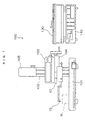
- FIG. 1 shows a front view of a contour shape measuring instrument using a measuring head according to the invention.
- a contour shape measuring instrument 100 is configured of a measuring section comprising a stool 101, a column 102 erected on the stool 101, a measuring head 10 having a sensing pin 15, a drive unit 103 for driving the measuring head 10 in its measuring direction, a manual inclining unit 104 for inclining the measuring head 10 and the drive unit 103, and an electric vertically shifting unit 105 for vertically shifting the measuring head 10, the drive unit 103 and the manual inclining unit 104, a control unit 110 for controlling measuring actions and analyzing measured data, and an XY recorder 120 for recording the measured results.
- a work W which is the object of measurement, is mounted on the stool 101.
- the whole measuring head 10 is linearly driven in the horizontal direction in a state in which the sensing pin is in contact with the work W, and the displaced quantity of the sensing pin is detected by a detector in the measuring head 10.
- the measuring head 10 and the drive unit 103 are inclined by the manual inclining unit 104.
- Detected data are delivered to the control unit 110, where the data are analyzed and measurements are recorded.
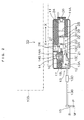
- Fig. 2 shows a side sectional view of the configuration of the measuring head 10.
- the measuring head 10 as shown in Fig. 2, comprises a body 11, a fulcrum member 12, a seesaw member 13, a differential transformer 14 which is the detector, the sensing pin 15, a tension spring 16 as the urging member, and a retracting device 20 among other elements.
- the seesaw member 13 comprises a seesaw block 13A, an arm 13B, a pin 13C, a weight 13D and a leaf spring 13E.
- To the tip of the arm 13B is fitted the sensing pin 15, while the base end of the arm 13B is inserted into a fitting hole (not shown) bored in the seesaw block 13A and pressed in the inserting direction by the leaf spring 13E.
- the weight 13D is fitted to the arm 13B, and its fitting position is adjustable. In the position of the seesaw block 13A reverse to the fitting position of the arm 13B is fitted the pin 13C.
- the fulcrum member 12 comprises a fulcrum shaft fixed to the seesaw block 13A and a bearing (not shown) fitted to the body 11, and swingably supports the seesaw member 13.
- the tip of the seesaw member 13 is urged downward by the tension spring 16 stretching between the body 11 and the seesaw block 13A as the urging member so that a measuring pressure be given to the sensing pin 15.
- This measuring pressure is adjusted by shifting the position of the weight 13D provided on the arm 13B.
- the measuring pressure rises, and when it is shifted toward the base end, the pressure lowers.
- the differential transformer 14 As the detector for detecting any displacement of the sensing pin 15, the differential transformer 14 is used. A coil 14A of the differential transformer 14 is provided in the body 11, while a core 14B of the differential transformer 14 is fitted to the seesaw block 13A. As its fitting position is on the other side than the sensing pin 15 with the fulcrum member 12 between them, the motion of the sensing pin 15 is converted into the motion of the core 14B, and is detected as an electrical signal of the differential transformer 14.
- a lower stopper 17 and an upper stopper 18 so as to regulate the stroke ends of the seesaw action of the seesaw member 13.
- the retracting device 20 which shifts the sensing pin from its measuring position to a predetermined retracting position and vice versa is built into the measuring head 10.
- the retracting device 20 comprises a feed screw 21, a nut 22 to screw onto the feed screw 21, an inclined member 23 formed on the nut 22 and an electric motor 24 to drive the feed screw 21.
- One end of the feed screw 21 is supported by the body 11 via a bearing (not shown) while its other end is connected to the shaft 24A of the electric motor 24 into which a decelerator 25 is incorporated via a coupling 29.
- a manual knob 26 To the other side of the electric motor 24 than the shaft 24A is fitted a manual knob 26.
- a stop 27 is fitted to the nut 22 and, as the stop 27 is loosely fitted into a long hole bored in the body, driving the feed screw 21 rotationally causes the nut 22 to shift linearly along the feed screw 21.
- two proximity switches 28 and 28 are disposed in the body 11. Being actuated by an approach of the stop 27, they detect one or the other of the stroke ends.
- the sensing pin 15, the arm 13B, the weight 13D and the manual knob 26 are exposed outside the cover 11A.
- the sensing pin 15 comes into contact with the face to be measured of the work W in a measuring position M shown in Fig. 2.
- the whole measuring head 10 is driven by the drive unit 103 in the measuring direction (the X-X direction in the drawing), and the face to be measured of the work W is traced by the tip of the sensing pin 15.
- the quantity of the displacement of the sensing pin 15 in the vertical direction is converted by the seesaw member 13 into the shift quantity of the core 14B of the differential transformer 14, and this quantity is supplied as an electrical signal.
- the measuring pressure in this process is set to an appropriate level by adjusting the tension spring 16 and the weight 13D.
- the feed screw 21 is turned with either the electric motor 24 or the manual knob 26 to shift the nut 22 leftward in the drawing.
- the inclined face 23A of the inclined member 23 formed on the nut 22 comes into contact with the pin 13C of the seesaw member 13.
- the pin 13C is shoved by the inclined face 23A to swing the seesaw member 13, and the shifting of the nut 22 is discontinued at the point of time when the proximity switch 28 on the left side of the drawing has detected the stop 27.
- the retracting speed and the returning speed of the sensing pin 15 can be set as desired by controlling the revolving speed of the electric motor 24. It is possible to set the retracting speed high and the returning speed low or to set either speed high in the initial phase of the pertinent action and low in its final phase.
- Fig. 4 shows a state in which the tip of the sensing pin 15 is stopped in an intermediate position P between the measuring position M and the retracting position R.
- the tip of the sensing pin 15 can be finely positioned as desired, it has been made possible to measure inner faces of thin holes, which was impossible by the prior art.
- the retracting device 20 has the manual knob 26, it is possible to manually retract the tip of the sensing pin to any desired position or to finely position it, enabling even complex shapes to be measured easily.
- the inclined member 23 has only one inclined face 23A in the embodiment of the invention described above, there may as well be disposed two inclined faces 23A and 23A with the pin 13C of the seesaw member 13 between them.
- the sensing pin 15 can be retracted upward with the upper inclined face 23A and downward with the lower inclined face 23A. Downward retraction is used when the sensing pin 15 is fitted upward to measure the upper face of a hole.
- the retracting speed and the returning speed of the sensing pin 15 are set by controlling the revolving speed of the electric motor 24, the speeds can as well be set by altering the lead of the feed screw 21 or the inclination angle of the inclined face 23A or by the combination of the alteration of the lead of the feed screw 21 or the inclination angle of the inclined face 23A and the control of the revolving speed of the electric motor 24.
Landscapes
- Physics & Mathematics (AREA)
- General Physics & Mathematics (AREA)
- A Measuring Device Byusing Mechanical Method (AREA)
- Length Measuring Devices With Unspecified Measuring Means (AREA)
Abstract
Description
- The present invention relates to a measuring head, and more particularly to a measuring head which is to be used in surface texture measuring instruments, contour shape measuring machines and the like and has a retractable device for shifting the sensing pin from its measuring position to a predetermined retracting position.
- A conventional surface texture measuring instrument, contour shape measuring instrument or the like for measuring the surface roughness or contour shape of a work has a sensing pin at the tip and a measuring head provided with a seesaw member supported to be swingable pivoting on a fulcrum member, a urging member for urging the seesaw member in one direction, and a detector arranged on the other side than the sensing pin with respect to the fulcrum member and detecting the displacement of the sensing pin by detecting the displacement of the seesaw member. By causing this measuring head to traverse along the measured face of the work and the sensing pin to trace the measured face, the surface roughness or contour shape of the work is measured.
- In a measuring head having such a structure, in order to protect the sensing pin when a work is set or any discontinuous face of the work is measured, there is provided a retracting device for moving the sensing pin.
- Such a conventional retracting device has a mechanism in which a solenoid is disposed near the seesaw member, and the sensing pin is moved from its measuring position to a prescribed retracting position and vice versa by turning on and off power supply to the solenoid and thereby swinging the seesaw member.
- Another retracting device has a mechanism in which a cam is turned by an electric motor, the seesaw member is swung by the lift of the cam, and the sensing pin is thereby caused to retract (e.g. see the Japanese Utility Model Application Publication No. 5-75606).
- However, the conventional retracting device using a solenoid swings the seesaw member by a certain angle by turning on or off the solenoid, and therefore involves a problem that no fine positioning is possible and stopping it on the way is not possible either. Nor does it permit manual retraction.
- Or the retracting device using an electric motor and a cam described in the Japanese Utility Model Application Publication No. 5-75606, though it can be equipped with a knob for manual operation use, can be stopped on the way only when it is electrically driven, and manual operation, for which the electric motor is released from excitation, cannot always stop the shift on the way. Accordingly it is unsuitable for fine positioning.
- An object of the present invention, attempted in view of these circumstances, is to provide a measuring head for use in surface texture measuring instruments, contour shape measuring instruments and the like, having a retracting mechanism capable of controlling the retracting speed and the returning speed of the sensing pin as desired, stopping the sensing pin on the way of its escaping action, permitting fine positioning and enabling the sensing pin to be retracted by manual operation as well.
- In order to achieve the object stated above, a measuring head according to a first aspect of the invention comprises:
- a sensing pin disposed at the measuring head's tip,
- a seesaw member which is supported to be swingable pivoting on a fulcrum member,
- an urging member which urges the seesaw member in one direction,
- a detector which is disposed on the other side than said sensing pin with respect to said fulcrum member and detects any displacement of said sensing pin by detecting the displacement of said seesaw member, and
- a retracting device which moves said sensing pin from its measuring position to a predetermined retracting position, wherein
- said retracting device comprises:
- an electric motor,
- a feed screw which is driven rotationally by the electric motor,
- a nut which screws onto the feed screw, is obstructed by a stop from turning, and is linearly moved along the feed screw by the turning of said feed screw, and
- an inclined member which is formed on the nut or coupled to the nut and has an inclined face which is in contact with said seesaw member on the other side than said sensing pin with respect to said fulcrum member, wherein
- said sensing pin being moved from its measuring position to the predetermined retracting position by linearly moving said inclined face to swing said seesaw member.
-
- According to this first aspect of the invention, as the retracting device of the sensing pin of the measuring head swings the seesaw member by linearly moving with the feed screw driven by the electric motor the inclined face in contact with the seesaw member to which the sensing pin is fitted, the retracting speed and the returning speed of the sensing pin can be set as desired, and the retracting action of the sensing pin can be stopped on the way to make possible its fine positioning.
- In a measuring head according to a second aspect of the invention, one side of the shaft of the electric motor in the configuration according to the first aspect of the invention is linked to the feed screw and the other side is fitted with a manual knob.
- According to this second aspect, not only can the sensing pin be manually retracted but also can its action be stopped on the way, making possible fine positioning of the sensing pin.
- In a measuring head according to a third aspect of the invention, the configuration according to the first of second aspect of the invention is further provided with sensors which detect the stroke ends of the nut linearly moving along the feed screw.
- According to this third aspect, as the stroke ends of the nut having the inclined face are detected by the sensors, the seesaw member to which the sensing pin is fitted can be prevented from swinging beyond its properly operable range, and accordingly the sensing pin is protected from damage.
- As described above, in the measuring head according to the invention, since the retracting device for the sensing pin has an electric motor-driven feed screw and an inclined face moved by the feed screw and the linear motion of the inclined face swings the seesaw member to which the sensing pin is fitted to retract the sensing pin, not only can the retracting speed and the returning speed of the sensing pin be controlled as desired but also can the retracting action of the sensing pin be stopped on the way to make possible its fine positioning.
- Further, as the electric motor is provided with the manual knob, not only can the sensing pin be manually retracted but also can its action be stopped on the way, making possible fine positioning of the sensing pin by manual action.
-
- Fig. 1 shows a front view of a contour shape measuring instrument provided with a measuring head according to the present invention;
- Fig. 2 shows a side sectional view of a state in which the sensing pin of a measuring head, which is a preferred embodiment of the invention, is in its measuring position;
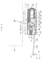
- Fig. 3 shows a side sectional view of a state in which the sensing pin of the measuring head, which is the preferred embodiment of the invention, is in its retracting position; and
- Fig. 4 shows a side sectional view of a state in which the sensing pin of the measuring head, which is the preferred embodiment of the invention, is stopped on the way.
-
- A measuring head, which is a preferred embodiment of the present invention, will be described in detail below with reference to the accompanying drawings, wherein like members will be designated by respectively like reference numerals or like reference characters.
- Fig. 1 shows a front view of a contour shape measuring instrument using a measuring head according to the invention. A contour
shape measuring instrument 100 is configured of a measuring section comprising astool 101, acolumn 102 erected on thestool 101, ameasuring head 10 having asensing pin 15, adrive unit 103 for driving themeasuring head 10 in its measuring direction, a manualinclining unit 104 for inclining themeasuring head 10 and thedrive unit 103, and an electric vertically shiftingunit 105 for vertically shifting themeasuring head 10, thedrive unit 103 and the manual incliningunit 104, acontrol unit 110 for controlling measuring actions and analyzing measured data, and anXY recorder 120 for recording the measured results. - A work W, which is the object of measurement, is mounted on the
stool 101. In the measuring action, the wholemeasuring head 10 is linearly driven in the horizontal direction in a state in which the sensing pin is in contact with the work W, and the displaced quantity of the sensing pin is detected by a detector in themeasuring head 10. - Where the inclined face of the work W is to be measured, the measuring
head 10 and thedrive unit 103 are inclined by the manual incliningunit 104. Detected data are delivered to thecontrol unit 110, where the data are analyzed and measurements are recorded. - Fig. 2 shows a side sectional view of the configuration of the
measuring head 10. Themeasuring head 10, as shown in Fig. 2, comprises abody 11, afulcrum member 12, aseesaw member 13, adifferential transformer 14 which is the detector, thesensing pin 15, atension spring 16 as the urging member, and a retracting device 20 among other elements. - The
seesaw member 13 comprises aseesaw block 13A, anarm 13B, apin 13C, aweight 13D and aleaf spring 13E. To the tip of thearm 13B is fitted thesensing pin 15, while the base end of thearm 13B is inserted into a fitting hole (not shown) bored in theseesaw block 13A and pressed in the inserting direction by theleaf spring 13E. - The
weight 13D is fitted to thearm 13B, and its fitting position is adjustable. In the position of theseesaw block 13A reverse to the fitting position of thearm 13B is fitted thepin 13C. - The
fulcrum member 12 comprises a fulcrum shaft fixed to theseesaw block 13A and a bearing (not shown) fitted to thebody 11, and swingably supports theseesaw member 13. - The tip of the
seesaw member 13 is urged downward by thetension spring 16 stretching between thebody 11 and theseesaw block 13A as the urging member so that a measuring pressure be given to thesensing pin 15. This measuring pressure is adjusted by shifting the position of theweight 13D provided on thearm 13B. Thus, when theweight 13D is shifted toward the tip of thearm 13B, the measuring pressure rises, and when it is shifted toward the base end, the pressure lowers. - As the detector for detecting any displacement of the
sensing pin 15, thedifferential transformer 14 is used. Acoil 14A of thedifferential transformer 14 is provided in thebody 11, while acore 14B of thedifferential transformer 14 is fitted to theseesaw block 13A. As its fitting position is on the other side than the sensingpin 15 with thefulcrum member 12 between them, the motion of thesensing pin 15 is converted into the motion of thecore 14B, and is detected as an electrical signal of thedifferential transformer 14. - Above the
seesaw block 13A of thebody 11 are disposed alower stopper 17 and anupper stopper 18 so as to regulate the stroke ends of the seesaw action of theseesaw member 13. - In order to protect the sensing pin when a work is set or when any discontinuous face of the work is measured, the retracting device 20 which shifts the sensing pin from its measuring position to a predetermined retracting position and vice versa is built into the
measuring head 10. - The retracting device 20 comprises a
feed screw 21, anut 22 to screw onto thefeed screw 21, aninclined member 23 formed on thenut 22 and anelectric motor 24 to drive thefeed screw 21. - One end of the
feed screw 21 is supported by thebody 11 via a bearing (not shown) while its other end is connected to the shaft 24A of theelectric motor 24 into which adecelerator 25 is incorporated via acoupling 29. To the other side of theelectric motor 24 than the shaft 24A is fitted amanual knob 26. - A
stop 27 is fitted to thenut 22 and, as thestop 27 is loosely fitted into a long hole bored in the body, driving thefeed screw 21 rotationally causes thenut 22 to shift linearly along thefeed screw 21. As sensors for detecting the two stroke end positions of thenut 22, twoproximity switches body 11. Being actuated by an approach of thestop 27, they detect one or the other of the stroke ends. - While the measuring
head 10 is shielded by acover 11A, thesensing pin 15, thearm 13B, theweight 13D and themanual knob 26 are exposed outside thecover 11A. - Next will be described the actions of the measuring
head 10 configured as described above. Thesensing pin 15 comes into contact with the face to be measured of the work W in a measuring position M shown in Fig. 2. Thewhole measuring head 10 is driven by thedrive unit 103 in the measuring direction (the X-X direction in the drawing), and the face to be measured of the work W is traced by the tip of thesensing pin 15. The quantity of the displacement of thesensing pin 15 in the vertical direction is converted by theseesaw member 13 into the shift quantity of the core 14B of thedifferential transformer 14, and this quantity is supplied as an electrical signal. The measuring pressure in this process is set to an appropriate level by adjusting thetension spring 16 and theweight 13D. - When the
sensing pin 15 is to be retracted from the measuring position M to the retracting position R, thefeed screw 21 is turned with either theelectric motor 24 or themanual knob 26 to shift thenut 22 leftward in the drawing. When thenut 22 is shifted leftward in the drawing, theinclined face 23A of theinclined member 23 formed on thenut 22 comes into contact with thepin 13C of theseesaw member 13. As thenut 22 is further shifted, thepin 13C is shoved by theinclined face 23A to swing theseesaw member 13, and the shifting of thenut 22 is discontinued at the point of time when theproximity switch 28 on the left side of the drawing has detected thestop 27. - This causes the tip of the
sensing pin 15 to retract to the retracting position R shown in Fig. 3. When thefeed screw 21 is turned in the reverse direction and thenut 22 is returned rightward in the drawing, the tip of thesensing pin 15 is returned to the measuring position M shown in Fig. 2. - As the retracting device 20 of the
sensing pin 15 functions by shifting in this way theinclined face 23A with thefeed screw 21 driven by theelectric motor 24, the retracting speed and the returning speed of thesensing pin 15 can be set as desired by controlling the revolving speed of theelectric motor 24. It is possible to set the retracting speed high and the returning speed low or to set either speed high in the initial phase of the pertinent action and low in its final phase. - It is also possible to stop the
sensing pin 15 in any desired position on the way between the measuring position M and the retracting position R. Fig. 4 shows a state in which the tip of thesensing pin 15 is stopped in an intermediate position P between the measuring position M and the retracting position R. - As the tip of the
sensing pin 15 can be finely positioned as desired, it has been made possible to measure inner faces of thin holes, which was impossible by the prior art. - Also, as the retracting device 20 has the
manual knob 26, it is possible to manually retract the tip of the sensing pin to any desired position or to finely position it, enabling even complex shapes to be measured easily. - To add, although the
inclined member 23 has only oneinclined face 23A in the embodiment of the invention described above, there may as well be disposed twoinclined faces pin 13C of theseesaw member 13 between them. In this case, thesensing pin 15 can be retracted upward with the upperinclined face 23A and downward with the lowerinclined face 23A. Downward retraction is used when thesensing pin 15 is fitted upward to measure the upper face of a hole. - While it was stated that the retracting speed and the returning speed of the
sensing pin 15 are set by controlling the revolving speed of theelectric motor 24, the speeds can as well be set by altering the lead of thefeed screw 21 or the inclination angle of theinclined face 23A or by the combination of the alteration of the lead of thefeed screw 21 or the inclination angle of theinclined face 23A and the control of the revolving speed of theelectric motor 24.
Claims (3)
- A measuring head (10) having at its tip a sensing pin (15) and further having a seesaw member (13) which is supported to be swingable pivoting on a fulcrum member (12), an urging member (16) which urges the seesaw member (13) in one direction, a detector (14) which is disposed on the other side than said sensing pin (15) with respect to said fulcrum member (12) and detects any displacement of said sensing pin (15) by detecting the displacement of said seesaw member (13), and a retracting device (20) which moves said sensing pin (15) from its measuring position to a predetermined retracting position, characterized in that
said retracting device (20) comprises:an electric motor (24),a feed screw (21) which is driven rotationally by the electric motor (24),a nut (22) which screws onto the feed screw (21), is obstructed by a stop (27) from turning, and is linearly moved along the feed screw (21) by the turning of said feed screw (21), andan inclined member (23) which is formed on the nut (22) or coupled to the nut (22) and has an inclined face which is in contact with said seesaw member (13) on the other side than said sensing pin (15) with respect to said fulcrum member (12), whereinsaid sensing pin (15) is moved from its measuring position to the predetermined retracting position by linearly moving said inclined face to swing said seesaw member (13). - The measuring head (10) according to claim 1, wherein one side of the shaft of said electric motor (24) is linked to said feed screw (21) and the other side is fitted with a manual knob (26).
- The measuring head (10) according to claim 1 or 2, further comprising sensors (28) which detect the stroke ends of the nut (22) linearly moving along said feed screw (21).
Applications Claiming Priority (2)
| Application Number | Priority Date | Filing Date | Title |
|---|---|---|---|
| JP2003154103 | 2003-05-30 | ||
| JP2003154103A JP3834817B2 (en) | 2003-05-30 | 2003-05-30 | Measuring head |
Publications (2)
| Publication Number | Publication Date |
|---|---|
| EP1482272A2 true EP1482272A2 (en) | 2004-12-01 |
| EP1482272A3 EP1482272A3 (en) | 2008-03-05 |
Family
ID=33128298
Family Applications (1)
| Application Number | Title | Priority Date | Filing Date |
|---|---|---|---|
| EP04253047A Withdrawn EP1482272A3 (en) | 2003-05-30 | 2004-05-24 | Measuring head |
Country Status (3)
| Country | Link |
|---|---|
| US (1) | US6901678B2 (en) |
| EP (1) | EP1482272A3 (en) |
| JP (1) | JP3834817B2 (en) |
Cited By (2)
| Publication number | Priority date | Publication date | Assignee | Title |
|---|---|---|---|---|
| CN104567792A (en) * | 2015-01-28 | 2015-04-29 | 李彦荣 | Handheld intelligent rock structure surface roughness coefficient measuring instrument |
| CN113418485A (en) * | 2021-06-08 | 2021-09-21 | 深圳市大族数控科技股份有限公司 | Thickness measuring device and thickness measuring method |
Families Citing this family (19)
| Publication number | Priority date | Publication date | Assignee | Title |
|---|---|---|---|---|
| IT1299902B1 (en) * | 1998-03-13 | 2000-04-04 | Marposs Spa | HEAD, EQUIPMENT AND METHOD FOR CHECKING LINEAR DIMENSIONS OF MECHANICAL PARTS. |
| JP4568621B2 (en) * | 2005-02-28 | 2010-10-27 | 株式会社ミツトヨ | Straightness correction method for surface texture measuring instrument and surface texture measuring instrument |
| DE102005034515B4 (en) * | 2005-07-20 | 2019-06-19 | Immobiliengesellschaft Helmut Fischer Gmbh & Co. Kg | Measuring stand for holding a measuring device |
| US7243437B1 (en) * | 2006-03-13 | 2007-07-17 | Armando Estrada | Decoding device for double-sided keys |
| JP5331645B2 (en) * | 2009-10-13 | 2013-10-30 | 株式会社ミツトヨ | Detector and measuring machine |
| JP5639934B2 (en) | 2011-03-09 | 2014-12-10 | 株式会社ミツトヨ | Surface texture measuring machine |
| FR2972526B1 (en) * | 2011-03-10 | 2016-05-20 | Commissariat Energie Atomique | DEVICE FOR MEASURING THE SURFACE CONDITION OF A SURFACE |
| JP5735337B2 (en) * | 2011-04-19 | 2015-06-17 | 株式会社ミツトヨ | Surface texture measuring machine |
| JP5823266B2 (en) * | 2011-11-29 | 2015-11-25 | 株式会社ミツトヨ | Surface texture measuring machine |
| CN102654395A (en) * | 2012-04-26 | 2012-09-05 | 华中科技大学 | Method for correcting nonlinear error of contact pin type contourgraph sensor |
| JP6282517B2 (en) * | 2014-04-09 | 2018-02-21 | 株式会社ミツトヨ | Shape measuring instruments |
| JP5846462B1 (en) * | 2014-10-28 | 2016-01-20 | 株式会社東京精密 | Shape measuring device |
| JP6630535B2 (en) | 2015-10-22 | 2020-01-15 | 株式会社ミツトヨ | Control method of shape measuring device |
| JP6848166B2 (en) * | 2017-03-27 | 2021-03-24 | 株式会社東京精密 | Contact control method for detectors, contour shape measuring machines and stylus |
| US11806867B2 (en) * | 2018-02-09 | 2023-11-07 | Konica Minolta, Inc. | Profiling apparatus |
| JP7261560B2 (en) * | 2018-10-31 | 2023-04-20 | 株式会社ミツトヨ | Surface texture measuring method and surface texture measuring device |
| KR102180526B1 (en) * | 2019-08-16 | 2020-11-18 | 한양대학교 산학협력단 | Potable surface measurement device and controlling method thereof |
| CN112345320A (en) * | 2020-10-20 | 2021-02-09 | 江南大学 | Method for micro-controlling two-dimensional material based on semi-automatic probe station |
| JP7050251B2 (en) * | 2021-02-26 | 2022-04-08 | 株式会社東京精密 | Contact control method for detector, contour shape measuring machine and stylus |
Citations (1)
| Publication number | Priority date | Publication date | Assignee | Title |
|---|---|---|---|---|
| JPH0575606U (en) | 1992-03-18 | 1993-10-15 | 株式会社東京精密 | Arm retraction mechanism for surface roughness profiler and contour profiler |
Family Cites Families (15)
| Publication number | Priority date | Publication date | Assignee | Title |
|---|---|---|---|---|
| US4187614A (en) * | 1978-08-04 | 1980-02-12 | Mitsubishi Jukogyo Kabushiki Kaisha | Tracer head |
| JPS58169001A (en) * | 1982-03-31 | 1983-10-05 | Mitsutoyo Mfg Co Ltd | Two-way touch sensor |
| DE3740070A1 (en) * | 1987-11-26 | 1989-06-08 | Zeiss Carl Fa | TURN SLEWING DEVICE FOR TEST COOKING OF COORDINATE MEASURING DEVICES |
| JPH0236083A (en) * | 1988-07-22 | 1990-02-06 | Kiyouhou Seisakusho:Kk | Pantograph robot arm |
| US5189806A (en) * | 1988-12-19 | 1993-03-02 | Renishaw Plc | Method of and apparatus for scanning the surface of a workpiece |
| DE3843125A1 (en) * | 1988-12-22 | 1990-06-28 | Zeiss Carl Fa | SWITCHING TYPE PROBE |
| JPH0575606A (en) | 1991-09-17 | 1993-03-26 | Nec Corp | Destination address collecting registering system |
| JP2860890B2 (en) * | 1995-08-25 | 1999-02-24 | 株式会社電元社製作所 | Pressurized drive for electric pressurized gun |
| JPH1125436A (en) * | 1997-07-02 | 1999-01-29 | Sony Tektronix Corp | Head movement stage mechanism for disk inspection device |
| IT1299902B1 (en) * | 1998-03-13 | 2000-04-04 | Marposs Spa | HEAD, EQUIPMENT AND METHOD FOR CHECKING LINEAR DIMENSIONS OF MECHANICAL PARTS. |
| JP3273026B2 (en) * | 1998-09-02 | 2002-04-08 | 株式会社ミツトヨ | Surface tracking type measuring machine |
| JP3992853B2 (en) * | 1998-09-30 | 2007-10-17 | 株式会社ミツトヨ | Surface following type measuring machine |
| US6765334B1 (en) * | 1999-09-21 | 2004-07-20 | Seiko Instruments Inc. | Linear or pivotal motion mechanism using ultrasonic motor and electronic device equipped with linear or pivotal motion mechanism |
| US6678964B2 (en) * | 2001-10-11 | 2004-01-20 | Robert Bosch Gmbh | Tracer device |
| JP3967274B2 (en) * | 2003-02-27 | 2007-08-29 | 株式会社ミツトヨ | measuring device |
-
2003
- 2003-05-30 JP JP2003154103A patent/JP3834817B2/en not_active Expired - Fee Related
-
2004
- 2004-05-24 EP EP04253047A patent/EP1482272A3/en not_active Withdrawn
- 2004-05-28 US US10/855,965 patent/US6901678B2/en not_active Expired - Fee Related
Patent Citations (1)
| Publication number | Priority date | Publication date | Assignee | Title |
|---|---|---|---|---|
| JPH0575606U (en) | 1992-03-18 | 1993-10-15 | 株式会社東京精密 | Arm retraction mechanism for surface roughness profiler and contour profiler |
Cited By (3)
| Publication number | Priority date | Publication date | Assignee | Title |
|---|---|---|---|---|
| CN104567792A (en) * | 2015-01-28 | 2015-04-29 | 李彦荣 | Handheld intelligent rock structure surface roughness coefficient measuring instrument |
| CN113418485A (en) * | 2021-06-08 | 2021-09-21 | 深圳市大族数控科技股份有限公司 | Thickness measuring device and thickness measuring method |
| CN113418485B (en) * | 2021-06-08 | 2023-10-13 | 深圳市大族数控科技股份有限公司 | Thickness measuring device and thickness measuring method |
Also Published As
| Publication number | Publication date |
|---|---|
| JP3834817B2 (en) | 2006-10-18 |
| US20050011078A1 (en) | 2005-01-20 |
| US6901678B2 (en) | 2005-06-07 |
| JP2004354289A (en) | 2004-12-16 |
| EP1482272A3 (en) | 2008-03-05 |
Similar Documents
| Publication | Publication Date | Title |
|---|---|---|
| US6901678B2 (en) | Measuring head | |
| JP5485676B2 (en) | Surface texture measuring machine | |
| JP3992853B2 (en) | Surface following type measuring machine | |
| JPH0557522B2 (en) | ||
| JP2007198791A (en) | Surface property measuring instrument | |
| JP2011085404A (en) | Detector and measuring device | |
| JP3928544B2 (en) | Method and apparatus for measuring screw characteristics | |
| WO2019155698A1 (en) | Surface shape measurement device | |
| JP2003315034A (en) | Surface texture measuring machine and method therefor, and measuring probe | |
| JP2525087Y2 (en) | Arm retraction mechanism for shape measuring machine | |
| JPH0460523B2 (en) | ||
| JP2539998B2 (en) | Shape measuring instruments | |
| JP4909562B2 (en) | Surface texture measuring device | |
| JPS6266102A (en) | Tilt angle measuring instrument for underside of work | |
| JP6583013B2 (en) | Roughness measuring machine | |
| CN214893058U (en) | Guiding rule for rapidly detecting wall surface flatness | |
| JP3534296B2 (en) | Surface texture measuring machine | |
| JPH0468776B2 (en) | ||
| JP2009204463A (en) | Wire type three-dimensional coordinate measuring machine | |
| JPS6338435Y2 (en) | ||
| JP3476627B2 (en) | Lens shape measuring device | |
| JPH10321674A (en) | Chip bonding head and method for measuring its parallelism to tool | |
| JPH0850003A (en) | Shape-measuring apparatus | |
| SU1392343A1 (en) | Size-measuring device | |
| JPH02181494A (en) | Lithography device |
Legal Events
| Date | Code | Title | Description |
|---|---|---|---|
| PUAI | Public reference made under article 153(3) epc to a published international application that has entered the european phase |
Free format text: ORIGINAL CODE: 0009012 |
|
| AK | Designated contracting states |
Kind code of ref document: A2 Designated state(s): AT BE BG CH CY CZ DE DK EE ES FI FR GB GR HU IE IT LI LU MC NL PL PT RO SE SI SK TR |
|
| AX | Request for extension of the european patent |
Extension state: AL HR LT LV MK |
|
| PUAL | Search report despatched |
Free format text: ORIGINAL CODE: 0009013 |
|
| AK | Designated contracting states |
Kind code of ref document: A3 Designated state(s): AT BE BG CH CY CZ DE DK EE ES FI FR GB GR HU IE IT LI LU MC NL PL PT RO SE SI SK TR |
|
| AX | Request for extension of the european patent |
Extension state: AL HR LT LV MK |
|
| RIC1 | Information provided on ipc code assigned before grant |
Ipc: G01B 7/012 20060101ALI20080131BHEP Ipc: G01B 5/012 20060101ALI20080131BHEP Ipc: G01B 5/28 20060101AFI20040921BHEP |
|
| 17P | Request for examination filed |
Effective date: 20080513 |
|
| AKX | Designation fees paid |
Designated state(s): DE GB |
|
| 17Q | First examination report despatched |
Effective date: 20100721 |
|
| STAA | Information on the status of an ep patent application or granted ep patent |
Free format text: STATUS: THE APPLICATION IS DEEMED TO BE WITHDRAWN |
|
| 18D | Application deemed to be withdrawn |
Effective date: 20150415 |